Abstract
District heating systems in northern China predominantly rely on coal-fired heat sources, necessitating sustainable alternatives to reduce carbon emissions. This study investigates a biomass combined heat and power (CHP) system integrated with cascaded absorption heat pump (AHP) technology to recover waste heat from semi-dry flue gas desulfurization exhaust and turbine condenser cooling water. A multi-source operational framework is developed, coordinating biomass CHP units with coal-fired boilers for peak-load regulation. The proposed system employs a two-stage heat recovery methodology: preliminary sensible heat extraction from non-saturated flue gas (elevating primary heating loop (PHL) return water from 50 °C to 55 °C), followed by serial AHPs utilizing turbine extraction steam to upgrade waste heat from circulating cooling water (further heating PHL water to 85 °C). Parametric analyses demonstrate that the cascaded AHP system reduces turbine steam extraction by 4.4 to 8.8 t/h compared to conventional steam-driven heating, enabling 3235 MWh of annual additional power generation. Environmental benefits include an annual CO2 reduction of 1821 tonnes, calculated using regional grid emission factors. The integration of waste heat recovery and multi-source coordination achieves synergistic improvements in energy efficiency and operational flexibility, advancing low-carbon transitions in district heating systems.
1. Introduction
In northern China, over 80% of urban buildings receive their heat from district heating (DH) systems [1]. The DH systems consist of heat sources, DH heat exchangers, a primary heating loop (PHL), consumer heat exchangers, and a secondary heating loop (SHL) [2]. In the existing DH systems in China, the available heat sources mainly come from coal-fired combined heat and power (CHP) units and coal-fired boilers [3].
Replacing coal energy with biomass energy in power plants is important in reducing air pollutants and CO2 emissions. Biomass CHP can provide low-carbon heat and electricity in the DH system and promote the achievement of carbon neutrality [4,5]. The heat and power generation efficiencies can be further increased by adopting the absorption heat pump (AHP) technologies, which can recover the waste heat from circulating cooling water or flue gas to achieve district heating and flue gas stripping [6,7,8,9,10]. Aydin et al.’s research demonstrates that absorption cycles are particularly suitable for low-grade heat utilization while effectively reducing thermal losses [11]. Mohammadi et al. further indicate that such systems can recover waste heat from flue gases, thereby significantly improving overall energy efficiency [12]. Innovative approaches for enhancing thermal efficiency in power plants with AHP have been explored by several researchers. Ifaei et al. [13,14] developed novel hybrid systems combining steam power plants with AHP to minimize water consumption in cooling towers, evaluating their performance through comprehensive energy, economic, and sustainability assessments. Alternative waste heat recovery methods were investigated by Vandani et al. [15], who examined the potential of utilizing boiler blowdown streams through detailed exergy-based evaluations. Previous studies have employed AHP technology to recover waste heat from circulating cooling water with three primary objectives: reducing the return water temperature in PHL, enhancing the heating capacity of PHL systems, and decreasing water flow rates in PHL networks [16]. However, when implementing AHP technology in biomass CHP systems for circulating cooling water heat recovery, an additional significant benefit emerges—the potential to increase power generation capacity. This enhanced electricity production consequently reduces carbon emissions from power generation, a synergistic effect achieved through the mitigation of energy losses and the reduction in exergy destruction in DH heat exchangers [17].
In the domain of flue gas waste heat recovery, Li et al. implemented an AHP system in a typical 330 MW coal-fired power plant, achieving significant thermal optimization by reducing the inlet flue gas temperature at the wet desulfurization tower to 100 °C and the outlet temperature to 46 °C, while simultaneously recovering latent heat from the flue gas stream [18]. Zhang et al. developed an innovative open-type AHP configuration to capture substantial amounts of water vapor and its associated latent heat from post-desulfurization coal-fired flue gases [19]. However, the ultra-low SO2 emission technologies originally developed for pulverized coal power plants demonstrate limited applicability in biomass-fired power generation systems. This discrepancy arises from fundamental differences in operational parameters, as biomass plants predominantly employ semi-dry flue gas desulfurization (FGD) processes utilizing calcium hydroxide (Ca(OH)2) or calcium oxide (CaO) powder as absorbents for multi-pollutant removal, including SO2, HCl, and HF [20,21,22,23]. Notably, the post-treatment flue gas in semi-dry FGD systems remains in a non-saturated state, fundamentally altering the heat recovery dynamics. Consequently, heat pump systems in this context primarily focus on sensible heat extraction from stack emissions rather than latent heat recovery, presenting distinct technical challenges compared to conventional coal-fired applications.
In DH systems, the conventional operational paradigm typically involves coordinated operation of CHP plants and peak-shaving boilers, where the latter primarily assumes responsibility for load flexibility during demand fluctuations. Previous investigations have focused on the thermal-hydraulic characteristics of PHL networks, the technical complexities arising from mixed return water temperatures in multi-user systems, and control methodologies for SHL regulation [24,25,26]. Li et al. [27] demonstrated the efficacy of AHP integration in enhancing thermal output capacity at SHL substations while developing corresponding operational control protocols. Their research premise assumes fixed flow rates in both PHL and SHL circuits throughout the heating season, employing constant flow regulation through supply/return water temperature modulation. Liu et al. [28] conducted comprehensive analyses of temperature-flow coordination strategies at SHL substations, proposing a model-predictive control framework to address thermal demand–supply mismatches, though notably omitting PHL network control considerations. Research demonstrates AHP systems enhance DH networks through multiple pathways. Razmi et al. show AHPs enable off-peak renewable integration, peak demand reduction, and waste heat utilization [29]. Brückner et al. establish a 3000 h operational threshold for industrial viability, with annuity factors critically influencing economics [30]. Lake et al. prove DH temperature gradients dictate thermal loss minimization [31]. Modern DH systems implement multi-layer control architectures incorporating three principal regulatory components in both PHL and SHL networks: (1) supply temperature controllers maintaining prescribed thermal gradients, (2) pressure differential maintenance controllers ensuring hydraulic stability, and (3) hydraulic balancing controllers optimizing flow distribution [32].
Nevertheless, it is critical to emphasize that existing research has predominantly focused on single-source heating configurations. In operational reality, biomass CHP plants typically provide baseload thermal supply, with coal-fired boilers functioning as auxiliary peak-shaving units. This study therefore initiates the systematic characterization of thermal response patterns in both PHL and SHL, particularly analyzing their supply–return temperature dynamics under varying ambient conditions within multi-source heating architectures. Subsequent investigation develops a novel cascaded heat recovery methodology: First-stage implementation of AHP technology targets sensible heat extraction from semi-dry FGD exhaust in biomass CHP plants, achieving preliminary temperature elevation of PHL return water. Second-stage integration combines AHP-based waste heat recovery from power plant steam condensers with conventional steam-water heat exchangers, enabling progressive heating of PHL circuits to meet DH operational requirements. The influence of some operating parameters on the COP is investigated. Compared with the original system where the return water is directly heated by the extracted steam, less energy and water consumption are achieved by the waste heat recovery system, which brings both economic and environmental benefits.
2. Methodology
2.1. The Description of the DH System
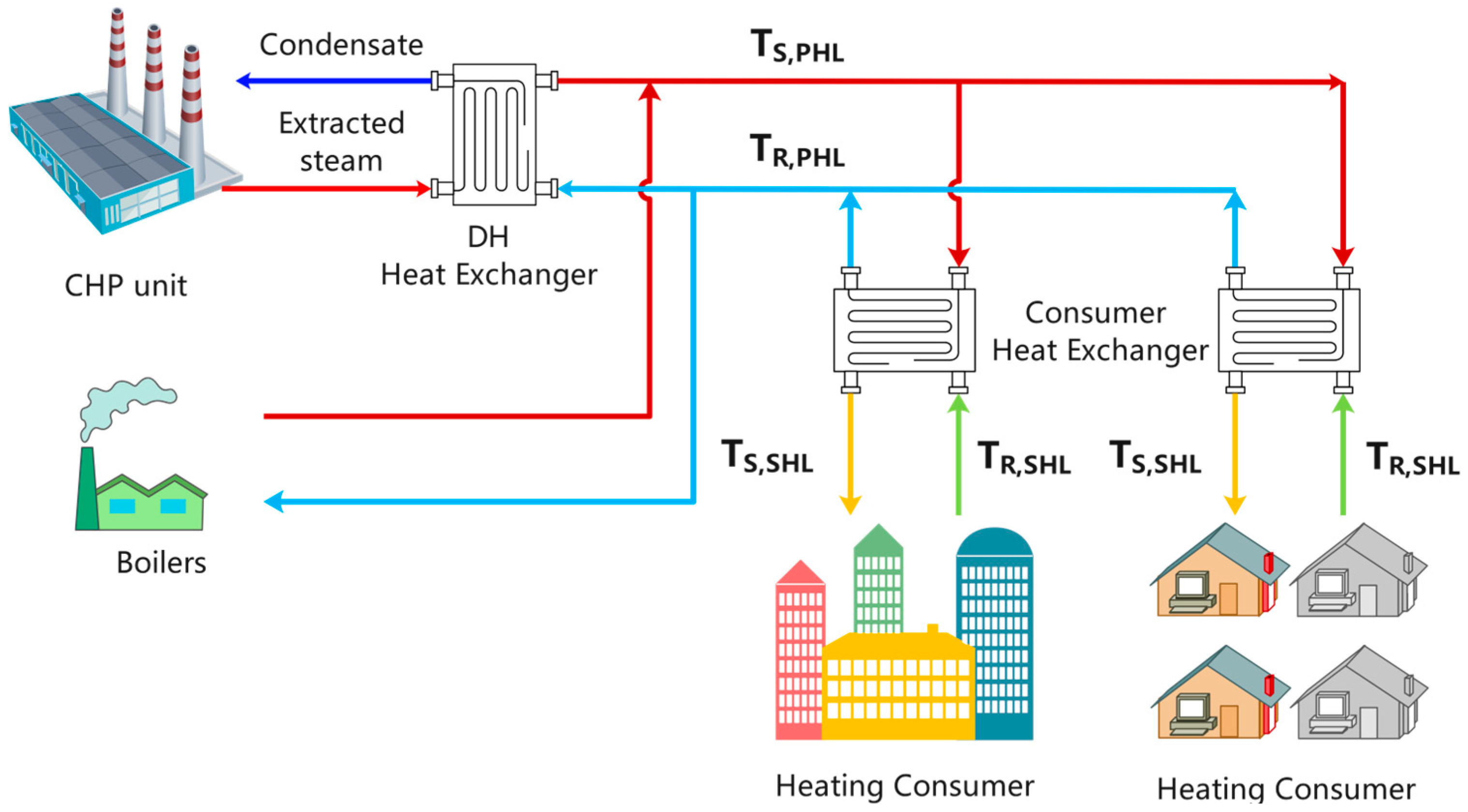
In this study, the DH system employs two heat sources, a biomass CHP unit and boilers, to provide heating for users, as illustrated in Figure 1. The engineering project considered for this study was in the Changchun city of the Jilin province of China (an ASHRAE 6A climate zone) [33,34]. The PHL return water was originally heated through a steam-water heat exchanger in the biomass CHP unit. The total heating area covers one million square meters, with a heating index of 56.3 W/m2. The biomass CHP unit has a rated power generation capacity of 40 MW, a maximum steam extraction capacity of 55 t/h, and a steam extraction pressure of 0.15 MPa. The CHP unit’s maximum heating capacity accounts for 65.28% of the peak heat demand, while the boilers’ maximum heating capacity makes up the remaining 34.72%. The ultimate and proximate analysis data of the biomass fuel are presented in Table 1.

Figure 1.
Schematic of a DH system with multi-heat sources.

Table 1.
The ultimate and proximate analysis data of the biomass fuel.
2.2. Parameters and Regulation Strategies of the SHL
To ensure indoor temperature requirements are met and high energy efficiency is maintained throughout the heating season, DH system’s regulation must be modified based on the fluctuations in the ambient temperatures.
In China’s actual SHL, quality regulation is predominantly employed due to the absence of control devices at end users. The supply and return water temperatures of the SHL are modified according to varying ambient temperatures, while the flow rates remain unchanged. Using the quality regulation method [35], Equations (1) and (2) determine the supply and return water temperatures of the SHL, as shown in Figure 1: TS,SHL and TR,SHL.
where tn (°C) denotes the indoor design temperature, and (°C) and (°C) are the designed SHL supply and return water temperatures, respectively.
The load ratio, , is defined as the proportion of the actual heating load at a specific outdoor temperature to the design heating load, as depicted in Equation (3).
where (°C) and (°C) are the designed and actual ambient temperatures, respectively.
2.3. Parameters and Regulation Strategies of the PHL
2.3.1. Combined Heating Utilizing CHP and Boilers
When the ambient temperature drops below (°C), the combined operation of the CHP and boilers is required to satisfy the heating demand. The value of can be calculated using Equation (4), where denotes the maximum designed heating capacity of the CHP [35].
The DH system employs a quantity regulation method. The supply water temperatures of the PHL (, as shown in Figure 1) are maintained at a constant level, as illustrated in Equation (5).
where (°C) is the designed PHL supply water temperature.
The flow rates () and return water temperatures of the PHL (, as shown in Figure 1) are adjusted based on different ambient temperatures. Equations (6)–(8) are used to calculate the values of and .
where (°C) is the designed PHL return water temperature.
When the CHP and boilers operate together to provide heating, the temperature of the PHL return water is elevated to the requisite temperature by both heat sources. Consequently, it is imperative to ascertain the individual flow rates of the CHP and boilers using Equations (9) and (10).
where and (°C) denote the PHL flow rate into the CHP and the return water temperature of the PHL, respectively, when the CHP attains its maximum designed heating capacity ().
2.3.2. Independent Heating with CHP
When the temperature exceeds , the CHP provides heating independently. The DH system employs a quality regulation method during this period, and the flow rates of the PHL remain constant, as illustrated in Equations (11) and (12).
The supply and return water temperatures of the PHL are adjusted according to varying ambient temperatures, as demonstrated in Equations (13)–(15).
where (°C) and (°C) denote the SHL supply and return water temperatures, respectively, when the CHP operates at its maximum designed heating capacity. The value of can be ascertained by employing Equations (16)–(18).
2.4. Flue Gas Heat Recovery System with AHP
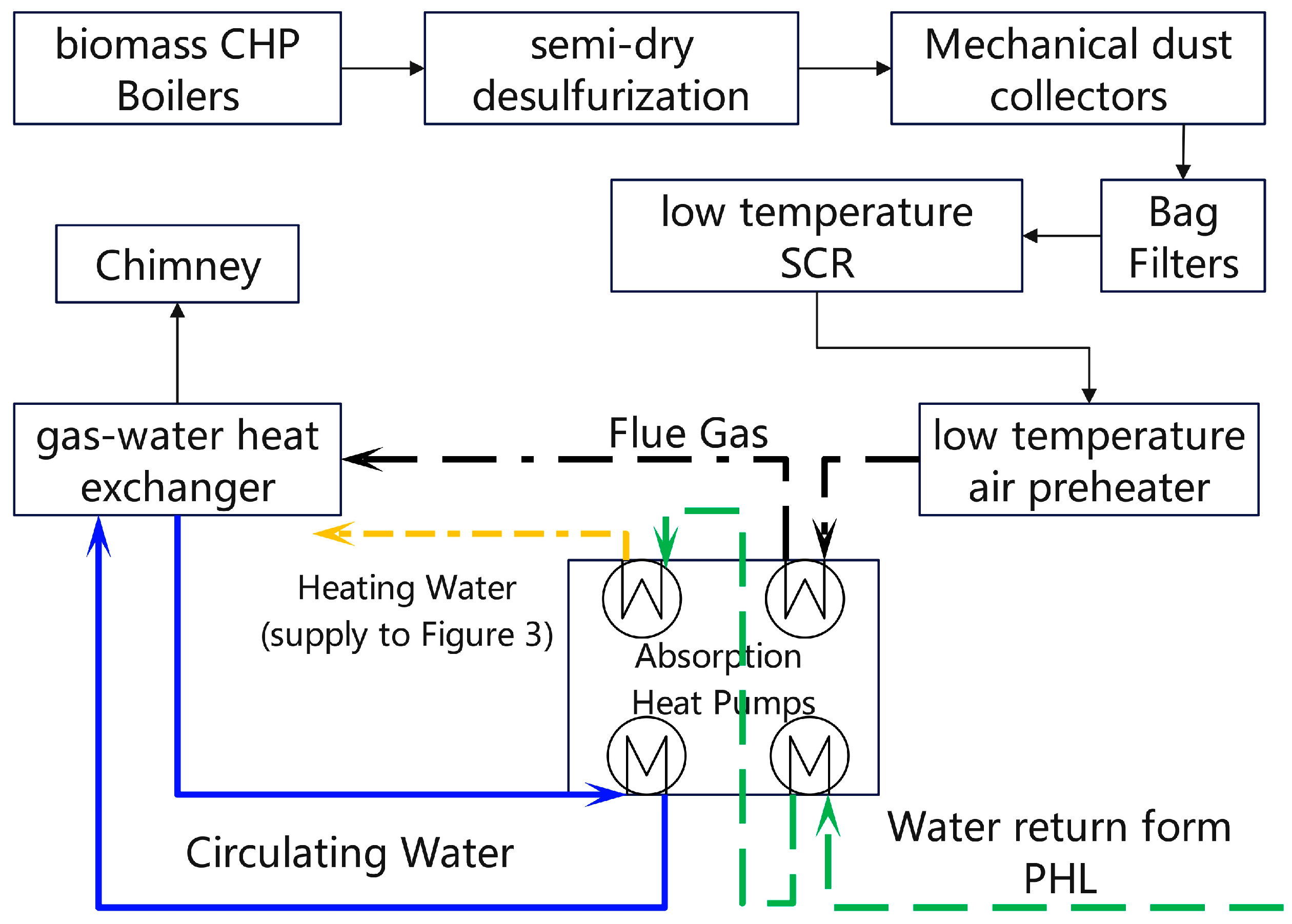
Figure 2 illustrates the flow chart of the flue gas heat recovery system. The flue gas temperature drops to 110 °C after passing through a series of flue gas purification devices and air preheaters. The AHP absorbs the sensible heat from the flue gas at the low temperature air preheater outlet, using it as the driving heat source to extract thermal energy from the chimney flue gas, thereby elevating the PHL return water temperature. As previously mentioned, biomass power plants adopt semi-dry desulfurization, resulting in the flue gas within the chimney not being saturated. Consequently, the heat extracted by the AHP is sensible rather than latent, contrasting with prior studies on flue gas heat recovery that were based on wet desulfurization in coal-fired power plants.
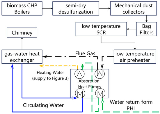
Figure 2.
Schematic of the flue gas heat recovery system.
As depicted in Figure 2, a gas-water heat exchanger transfers heat from the flue gas to the AHP evaporator. The circulating water is cooled in the AHP evaporator from 45 °C to 37 °C, acting as a low-temperature heat source. It is then pumped back to the gas-water heat exchanger, where it absorbs heat from the flue gas and subsequently raises its temperature from 37 °C to 45 °C. The AHP utilizes the recovered heat to raise the PHL return water temperature from 50 °C to 55 °C. The heated PHL return water is subsequently directed to the serial absorption heat pumps illustrated in Figure 3 for further heating.
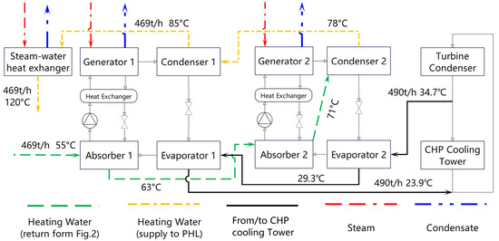
Figure 3.
Schematic of the improved heating supply system with serial absorption heat pumps.
To determine the applicability of the heat recovery system, it is first necessary to establish the enthalpy value of the flue gas. The flue gas enthalpy is a function of its temperature and moister content. As shown in Equation (19), the enthalpy of the flue gas comprises both the enthalpy of the dry flue gas (hdg, kJ/kg) and the water vapor (hv, kJ/kg). After passing through the purification devices, the primary constituents of the dry flue gas are CO2, N2, and O2. The concentrations of NOx and SOx are minimal and thus negligible in enthalpy calculations. The mass percentages (, %) of CO2, N2, and O2 in the flue gas can be derived from the ultimate and proximate analysis data of biomass found in Table 1 [36]. Using Equation (20) and the data in Table 2, the enthalpy of the dry flue gas can be calculated, where T represents the flue gas temperature (the unit is the Kelvin scale, K) [37].
Table 2.
Coefficients to calculate the enthalpy of the flue gas.
The enthalpy of the water vapor can be determined using Equations (21)–(23) [38] and the data in Table 2. Water vapor in the flue gas can exist in either superheated () or saturated states (). To ascertain the enthalpy of water vapor in the superheated state, it is necessary to determine the saturated vapor pressure (Psat, Pa) at various flue gas temperatures using the Antoine equation (Equation (24)) [39]. This enables the calculation of the moisture content (d, kg/kg dry flue gas) of the flue gas by Equation (25) and the relative humidity (, %) by Equation (26). In Equation (25) [9], Mv (g/mol) and Mdg (g/mol) denote the molar masses of water vapor and dry flue gas, respectively, while Pv represents the partial pressure of water vapor (Pa) and P represents the total pressure of the flue gas (Pa).
2.5. Waste Heat Recovery of CHP with Serial Absorption Heat Pump
After being heated by the flue gas heat recovery system, the PHL return water is further heated by the serial AHP, which is powered by steam extracted from the turbine at a pressure of 0.15 MPa. It captures heat from the turbine condenser’s circulating cooling water and raises the temperature of the PHL’s return water. The PHL and the turbine condenser’s circulating cooling water are separate systems, ensuring that the PHL’s return water does not enter the turbine condenser. The AHP can increase the return water temperature from 55 °C to 85 °C. Subsequently, the steam-water heat exchanger further heats the preheated return water to 120 °C before it is returned to the PHL, as illustrated in Figure 3.
In the Changchun region (classified as an ASHRAE 6A climate zone), winter temperatures are quite low. The biomass CHP operates at a back pressure of 4.9 kPa, with the turbine condenser’s circulating cooling water having inlet and outlet temperatures of 23.9 °C and 34.7 °C, respectively. This results in low evaporating temperatures for the refrigerant in the AHP’s evaporator, which adversely affects safe operation. To mitigate the risk of crystallization, a serial configuration of two absorption heat pumps is employed. As depicted in Figure 3, the external loops of the two absorption heat pumps are interconnected. The condenser’s cooling water flows into the evaporators, and the return water is sequentially heated by absorber 1, absorber 2, condenser 2, and condenser 1 [10].
3. Results and Discussions
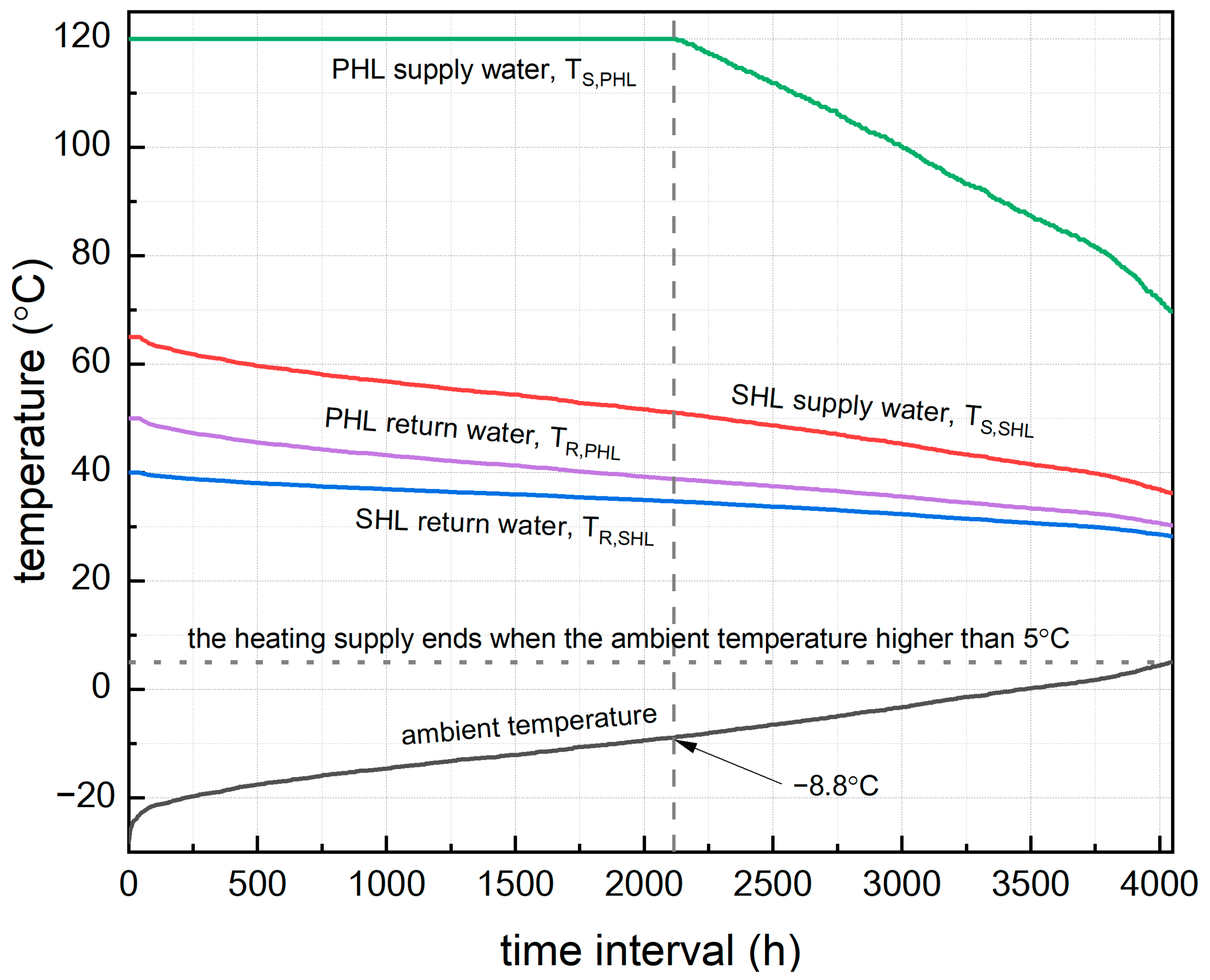
The district heating system’s design parameters are detailed in Table 3. Under the specified conditions, the SHL’s supply and return temperatures are 65 °C and 40 °C, respectively. For the PHL, the temperatures are set at 120 °C for supply and 50 °C for return. The heating season spans from 20 October to 6 April of the following year. Hourly ambient temperatures during this period are sourced from the DesignBuilder building energy modeling platform [40]. These temperatures are organized in ascending order, as illustrated in Figure 4. The horizontal axis indicates the cumulative hours from the start to the end of the heating season. The limit temperature for CHP standalone heating () can be determined to be −8.8 °C, based on Equation (4) and the maximum designed heating capacity of the CHP ().
Table 3.
Design parameters of the DH system.
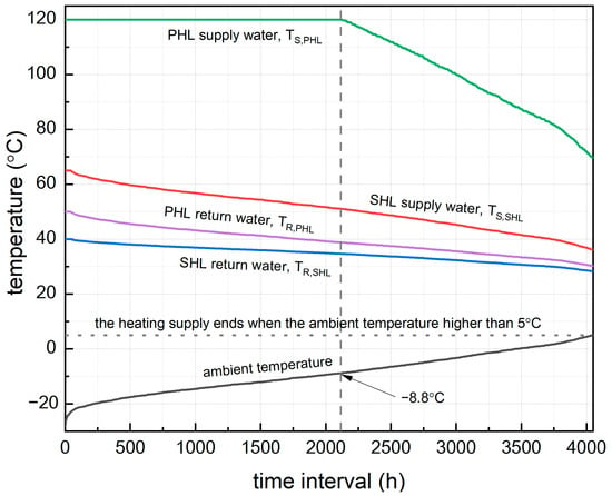
Figure 4.
The supply and return temperatures of PHL and SHL at different ambient temperatures.
3.1. Changes in Temperature and Flow Rates of PHL and SHL Under Different Ambient Temperatures
This DH system consists of biomass CHP and boilers, delivering thermal energy to an area of one million square meters via a heating network, as illustrated in Figure 1. The system uses an indirect connection method, linking end-users to the heat sources via the heating network.
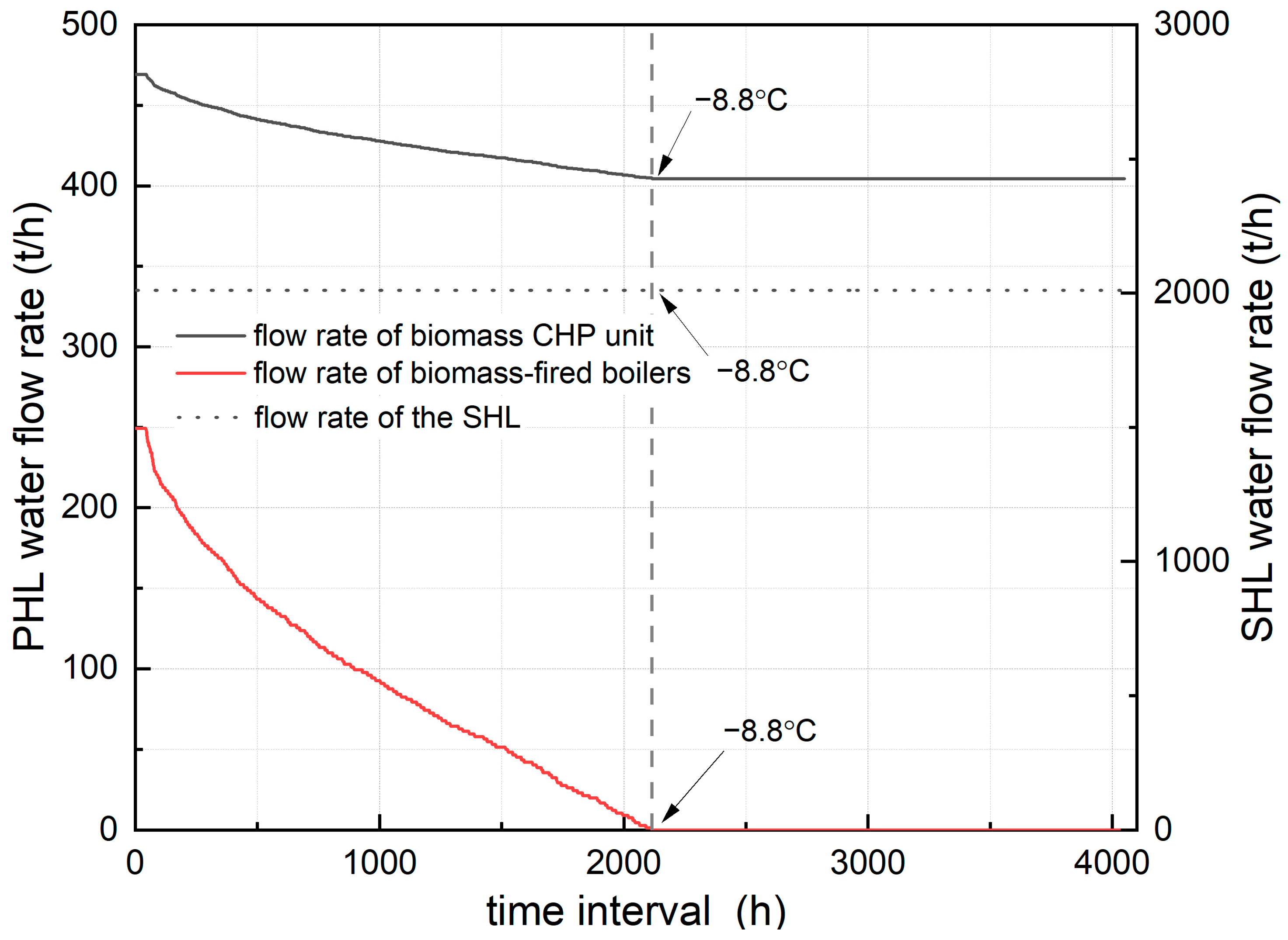
When the ambient temperature is at or above −8.8 °C (), the CHP alone can meet the heating demand. The heating supply is regulated through a quality control method. The supply and return water temperatures of PHL gradually decrease with an increase in ambient temperature, correlating with a reduction in heat load (as depicted in Figure 4). The flow rate of PHL is maintained at 404.5 t/h (as illustrated in Figure 5). Heat regulation is achieved by managing the temperature differential between the supply and return water of PHL.
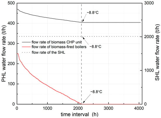
Figure 5.
The flow rates of PHL and SHL at different ambient temperatures.
When temperatures range from −8.8 °C to −23 °C (), the CHP operates at full capacity, and boilers gradually contribute until the combined output satisfies the system’s design requirements. A quantity control method is necessary to maintain stable operation. At this stage, the water supply volume from both CHP and boiler sources adjusts according to ambient temperature changes. As the ambient temperature decreases, the PHL water flow rate increases, with the CHP system handling an increase from 404.5 t/h to 469.2 t/h, and the boilers managing a rise from 0 t/h to 249.2 t/h (as shown in Figure 5). When the ambient temperature falls below −8.8 °C (), the PHL employs a constant water supply temperature (120 °C) to regulate heat supply by varying the PHL water flow rate, as shown in Figure 4.
During the quality control phase, reduced circulation flow minimizes the system’s energy consumption. Additionally, the SHL network also utilizes quality control, allowing the entire system to maintain a lower temperature differential between the supply and return water at the start and end of the heating period. Previous research using a single heat source indicated that PHL and SHL supply and return water temperatures linearly correlated with outdoor temperature variations, while their water flow rates remained constant. The DH system in this study, compared to traditional single-source heating systems, offers superior adaptability and energy efficiency [27,28].
3.2. Heat Recovery from Waste Heat
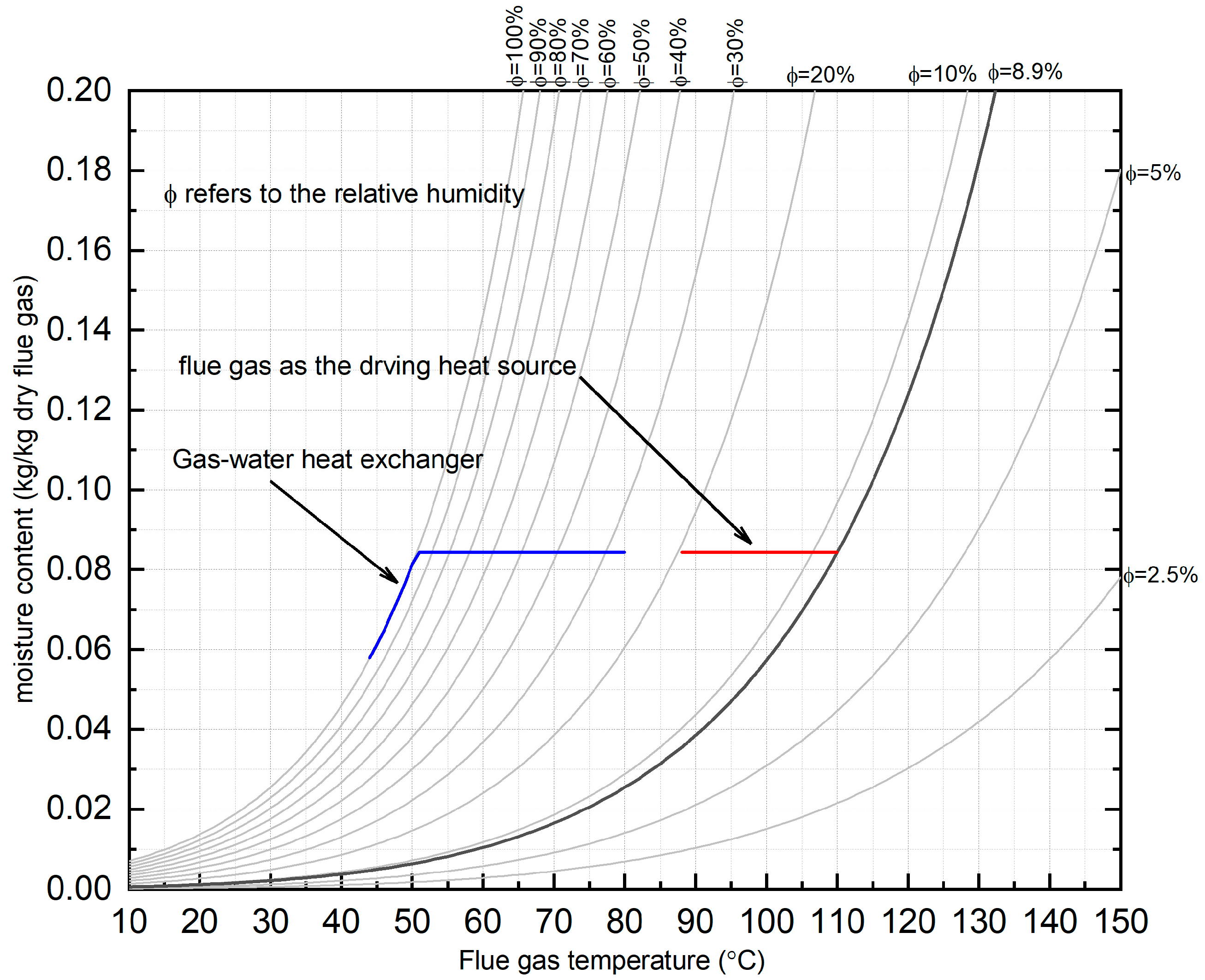
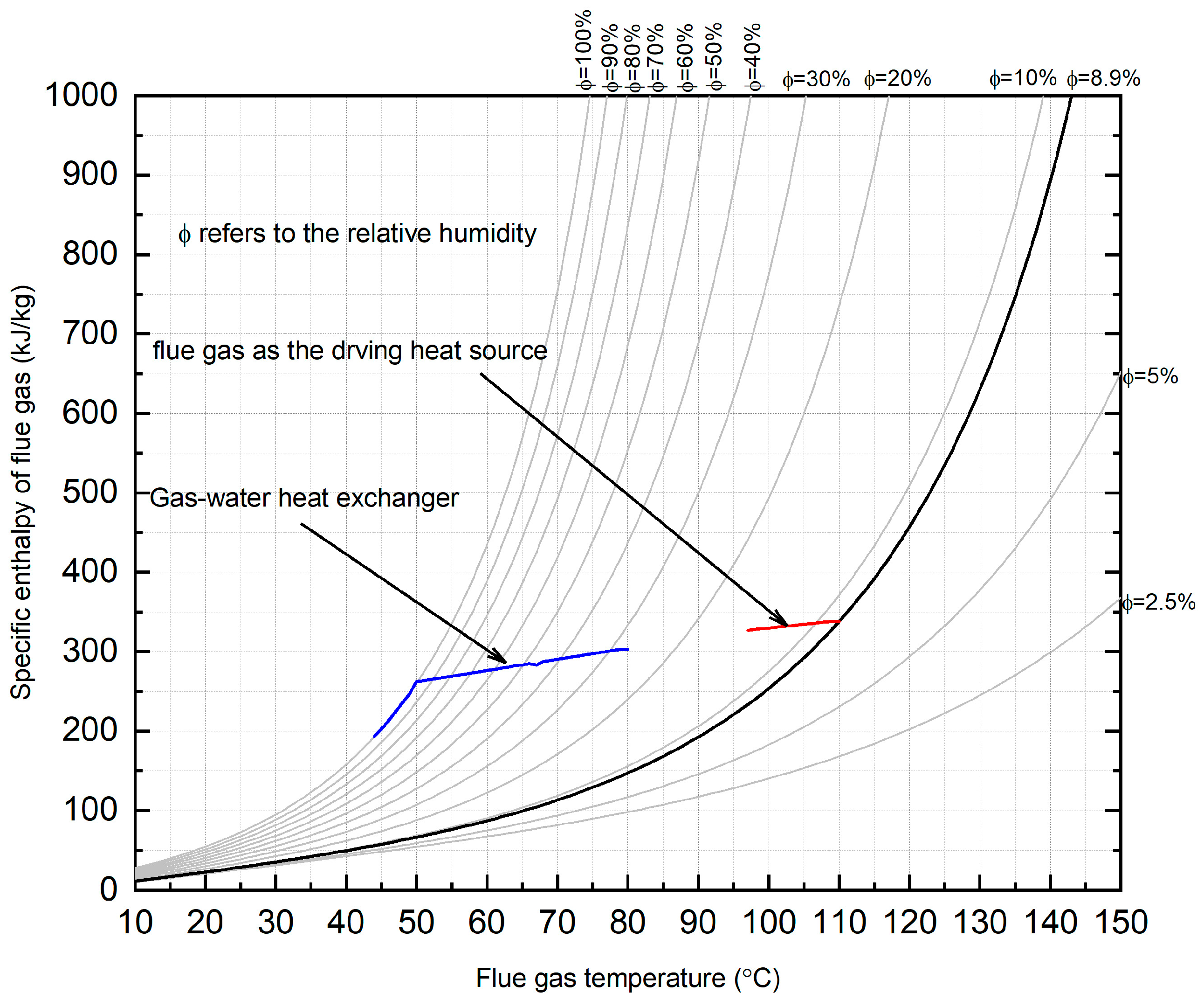
Based on the data in Table 1, the flue gas flow rate at the outlet of the low temperature air preheater is calculated to be 206 t/h, with a molar mass of 30.65 g/mol and a moisture content of 0.084 kg/(kg dry flue gas). Using Equations (19)–(26), the temperature-humidity diagram (Figure 6) and enthalpy-temperature diagram (Figure 7) of the flue gas can be plotted. The dark curves in Figure 6 and Figure 7 indicate that the relative humidity of the flue gas at the outlet of the low temperature air preheater is 8.9%. Unlike wet desulphurization systems, the biomass unit utilizes semi-dry desulphurization [18,41,42], where flue gas moisture primarily derives from ambient air and biomass combustion. The negligible contribution of desulphurization to vapor content prevents saturation at the preheater outlet.
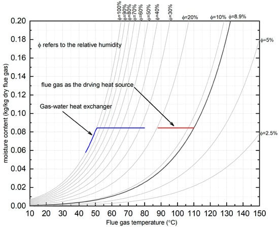
Figure 6.
Temperature-humidity diagram of flue gas.
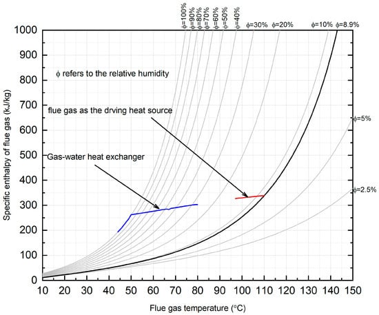
Figure 7.
Enthalpy-temperature diagram of flue gas.
As illustrated in Figure 6, the flue gas acts as the driving heat source, cooling from 110 °C to 88 °C at constant moisture content (0.084 kg/kg dry flue gas). The resultant drop in saturation pressure raises the relative humidity from 8.9% to ~20%. During this phase, only sensible heat is recovered, reducing the enthalpy from 338.09 kJ/kg to 317.61 kJ/kg (Figure 7). Further cooling via the flue gas-water heat exchanger (Figure 2) lowers the temperature from 80 °C to 51 °C, achieving 100% relative humidity (Figure 6). Subsequent condensation below the dew point enables simultaneous recovery of sensible and latent heat, along with water vapor capture. The flue gas eventually reaches 44 °C, with moisture content and enthalpy declining to 0.058 kg/(kg dry flue gas) and 192.94 kJ/kg, respectively.
The 110 °C flue gas exiting the low-temperature air preheater serves as the driving heat source, but its temperature is insufficient to generate higher-temperature refrigerants in the generator. Consequently, the flue gas heat recovery system shown in Figure 2 can only elevate the PHL return water temperature to a maximum of 55 °C. Previous studies have demonstrated that increasing flue gas temperature enables higher PHL return water heating, significantly improving the system’s coefficient of performance (COP). However, in biomass power plants, the flue gas temperature is substantially reduced after passing through a series of purification devices and air preheaters, limiting further temperature rise in the PHL return water [17,43]. Thus, this study fixes the outlet water temperature at 55 °C. As the PHL return water temperature decreases, the temperature difference across the AHP increases, allowing more heat to be recovered from the flue gas (see Figure 8).
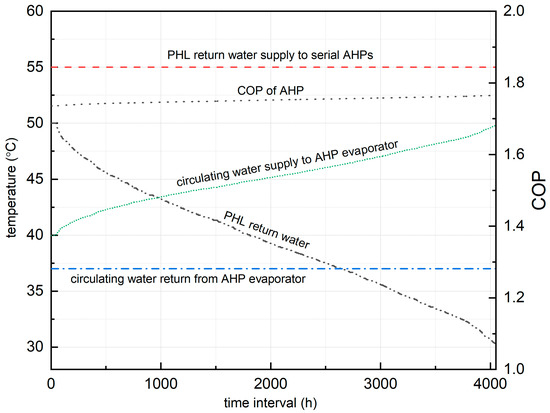
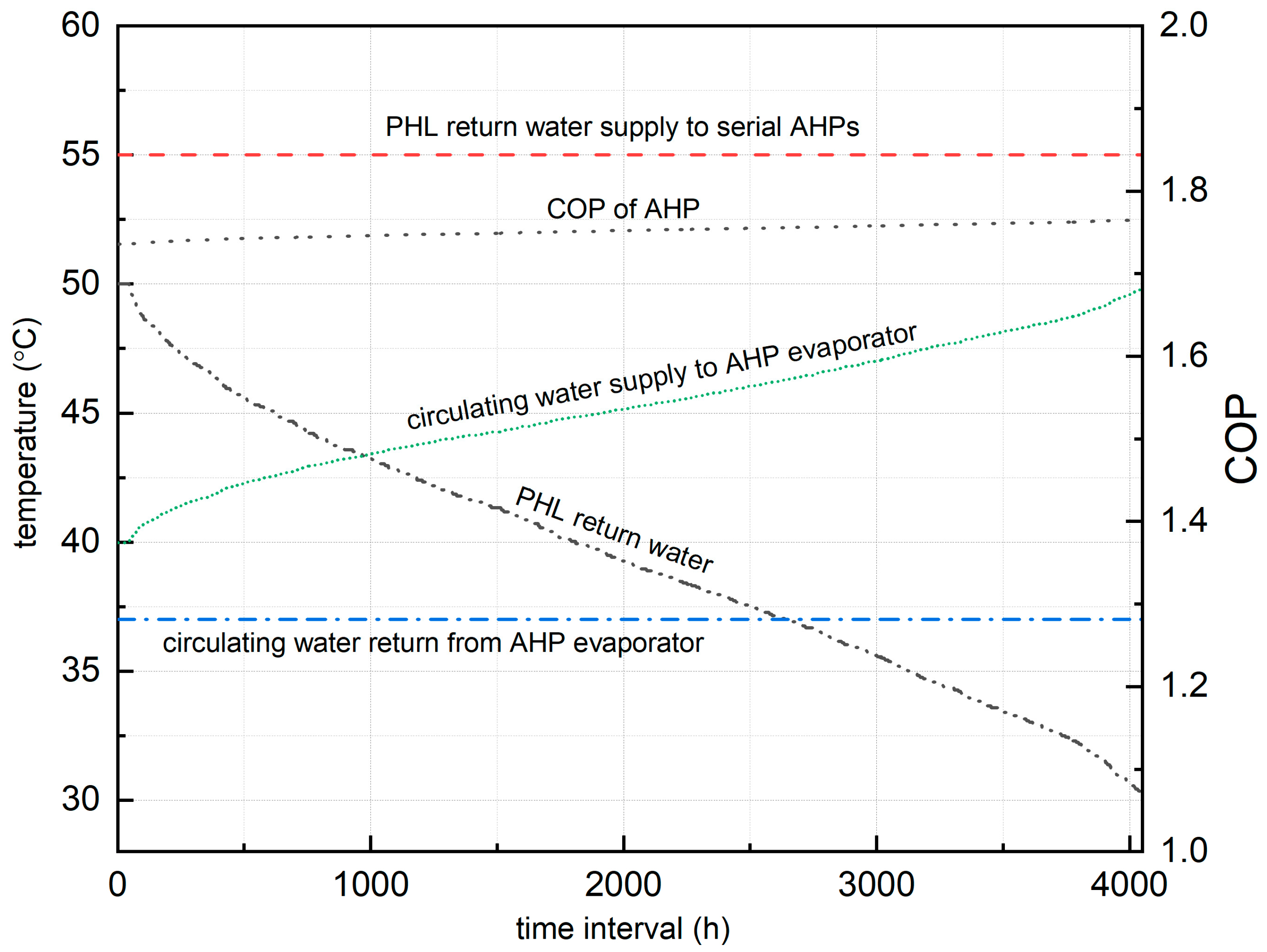
Figure 8.
Temperature profiles and COP trends in the AHP system.
In Figure 8, the heating demand declines progressively with rising ambient temperature, causing the PHL return water temperature to decrease from 50 °C to 30.29 °C. The AHP is employed to generate low-temperature circulating water, thereby achieving lower flue gas exhaust temperatures and enhanced heat recovery. The circulating water flow rate downstream of the flue gas-water heat exchanger remains constant at 360 t/h. Meanwhile, the supply water temperature to the AHP evaporator gradually increases to meet heating requirements. To maintain the economic viability and operational safety of the AHP cycle, the return water temperature of the circulating water is kept nearly constant. Figure 8 also reveals a slight downward trend in the AHP’s COP as the PHL return water temperature rises. This reduction in COP can be attributed to two factors: (1) diminished heat absorption by the higher-temperature water in the absorber, and (2) reduced absorption heat generation in the evaporator due to declining solution concentration.
3.3. Heat Recovery from Circulating Cooling Water
Figure 1 illustrates the conventional DH system under design conditions where the PHL return water at 50 °C is heated to 120 °C in the steam-water heat exchanger using approximately 0.15 MPa steam extracted from the turbine at a flow rate of 55 t/h. This conventional DH system presents two notable inefficiencies. First the large temperature difference between the 0.15 MPa steam and the 50 °C return water leads to considerable exergy loss during heat transfer. Second while winter ambient temperatures average −9.8 °C, the turbine condenser’s cooling water with inlet and outlet temperatures of 23.9 °C and 34.7 °C, respectively, discharges this low-grade thermal energy to the environment through cooling towers. To conserve this waste heat and reduce system inefficiencies serial AHPs are implemented, as shown in Figure 3. In this modified system, turbine extraction steam acts as the driving heat source to recover thermal energy from the cooling water.
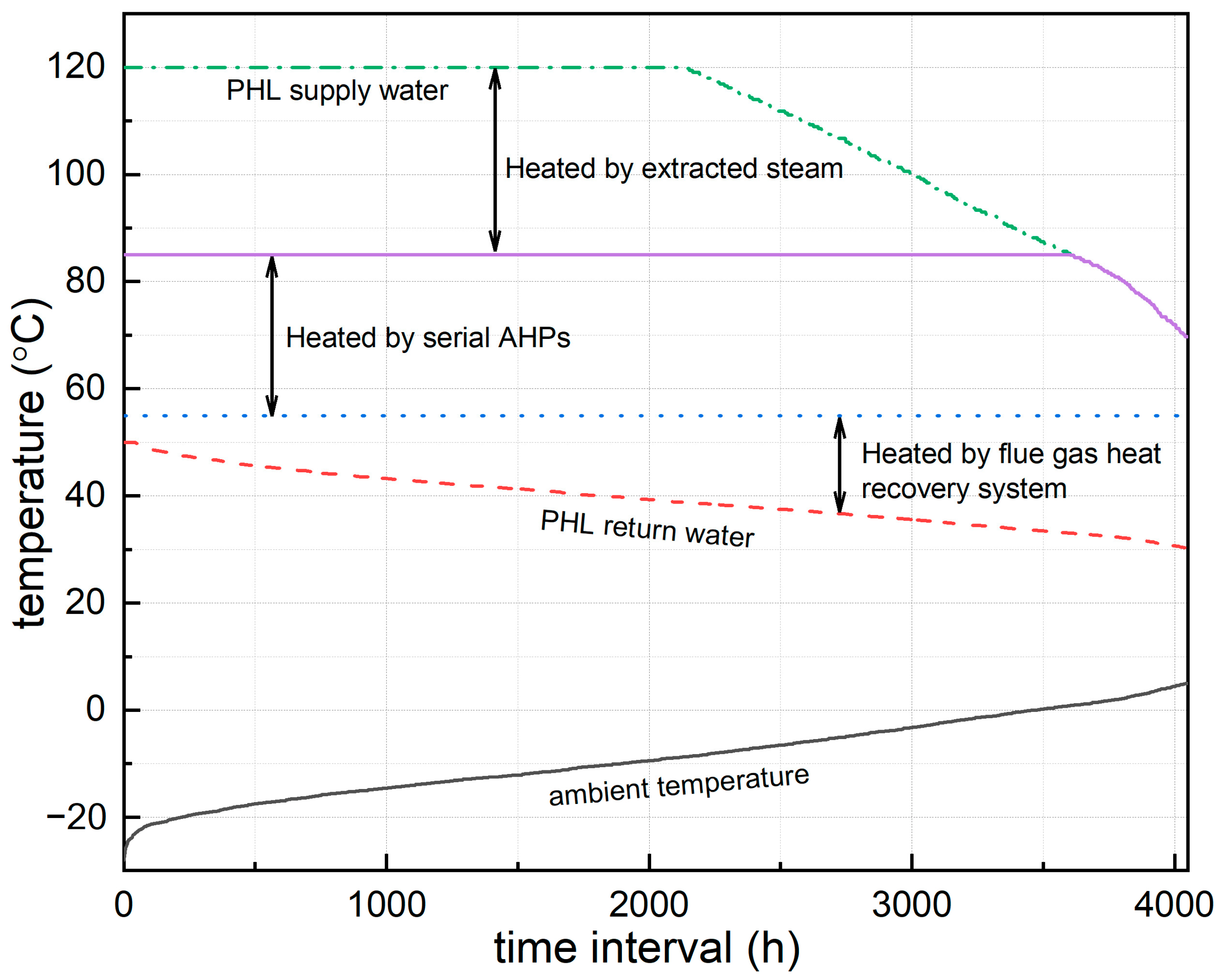
Under CHP-only operation conditions with decreasing ambient temperatures from 5 °C to −8.8 °C, the PHL maintains a constant flow rate while exhibiting a temperature rise from 69 °C to 120 °C (Figure 9). Within this operational regime, the serial AHPs provide dedicated heating capacity for the 69–85 °C temperature range, thereby eliminating steam-water heat exchanger requirements for this thermal load segment. During combined CHP-boiler operation at lower ambient temperatures (−8.8 °C to −28.5 °C), the system maintains stable return water temperatures at 120 °C while modulating flow rates: the CHP circuit demonstrates a flow rate increase from 404.5 t/h to 469.2 t/h, complemented by boiler circuit activation with flow rates rising from 0 t/h to 249.2 t/h (Figure 5). The thermal integration system employs serial AHPs to elevate return water temperature from 55 °C to 85 °C (Figure 9), with subsequent steam-water heat exchange completing the thermal upgrade to the required 120 °C network supply temperature.
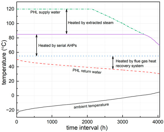
Figure 9.
Temperature profiles in the serial AHPs system.
The implementation of serial AHPs demonstrates significant energy savings, reducing turbine steam extraction by 4.4–8.8 t/h compared to conventional DH systems (Figure 10). This efficiency improvement is achieved through thermal upgrading of waste cooling water heat via the AHP system, which repurposes this previously dissipated energy source for return water preheating applications. The conserved steam enables substantial additional biomass power generation capacity of 3235 MWh annually. From an environmental perspective, this corresponds to an annual CO2 emissions reduction of 1821.24 metric tons, calculated using Jilin Province’s 2021 grid emission factor (0.5629 kg CO2/kWh). This quantification method follows standard protocols for assessing carbon mitigation in thermal energy systems.
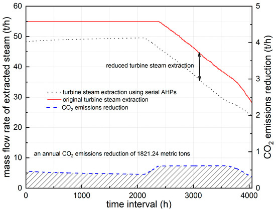
Figure 10.
Reduction in turbine steam extraction and CO2 through AHPs implementation.
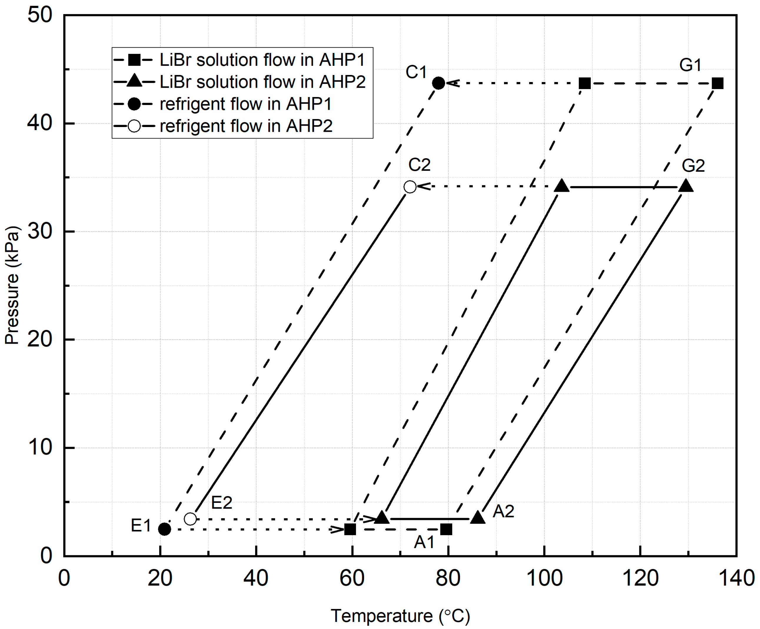
The serial AHPs system’s thermodynamic performance is depicted in Figure 11, featuring two coupled thermodynamic cycles (G1-C1-E1-A1 and G2-C2-E2-A2) that align with the system layout presented in Figure 3. Operational parameters exhibit adaptive characteristics, with the evaporator’s feedwater temperature adjusting automatically in response to environmental variations to ensure efficient heat delivery. During operation, both the strong and weak solution concentrations progressively decline in parallel with the deflation ratio, which is carefully regulated between 0.03 and 0.06 to guarantee both economic operation and system reliability.
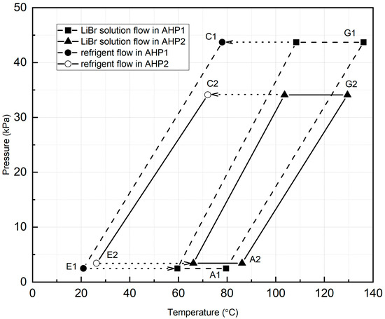
Figure 11.
Thermodynamic cycles of serial AHPs.
To maintain stable operation and avoid crystallization risks, real-time monitoring of the LiBr-H2O solution properties is conducted using the Dühring diagram [44,45,46], with solution concentrations consistently maintained above the crystallization boundary. The system’s thermal output is characterized by four distinct temperature stages, providing enhanced compatibility with applications requiring significant temperature variations.
4. Conclusions
This study demonstrates the technical and economic viability of integrating biomass CHP with cascaded AHP systems for low-carbon district heating. The principal research outcomes are summarized as follows:
The two-stage heat recovery system effectively addresses the challenges of sensible heat extraction from semi-dry FGD flue gas (non-saturated at 110 °C) and enables efficient utilization of low-grade waste heat from biomass CHP, achieving a 55 °C to 85 °C temperature lift in PHL return water.
Multi-source coordination between biomass CHP (base load) and coal-fired boilers (peak load) optimizes thermal-hydraulic stability, reducing PHL flow rate fluctuations by 34.7% under variable ambient temperatures (−28.5 °C to 5 °C).
The environmental benefits are quantified through an annual CO2 emission reduction of 1821 tonnes, coupled with 3235 MWh of additional biomass-based power generation enabled by operational steam savings. These improvements stem from reduced coal utilization and optimized waste heat recovery efficiency within the integrated system.
The proposed system offers a replicable framework for transitioning conventional coal-dependent DH systems toward carbon neutrality. Future work should explore hybrid configurations incorporating solar thermal energy to further minimize reliance on fossil-fueled peak-shaving units.
Author Contributions
Conceptualization, P.W.; methodology, P.W.; software, H.Z.; validation, P.W.; formal analysis, P.W. and H.Z.; writing—original draft preparation, P.W. and H.Z.; writing—review and editing, P.W.; funding acquisition, P.W. All authors have read and agreed to the published version of the manuscript.
Funding
This research was funded by the Scientific Research Program of Jilin Provincial Department of Education, grant number JJKH20240424KJ.
Institutional Review Board Statement
Not applicable.
Informed Consent Statement
Not applicable.
Data Availability Statement
The data presented in this study are available on request from the corresponding author due to contractual obligations with study participants that prohibit open data sharing.
Conflicts of Interest
The authors declare no conflicts of interest.
Abbreviations and Nomenclatures
The following abbreviations and nomenclatures are used in this manuscript:
| DH | district heating |
| PHL | primary heating loop |
| SHL | secondary heating loop |
| CHP | combined heat and power |
| AHP | absorption heat pump |
| FGD | flue gas desulfurization |
| TS,SHL | the supply water temperatures of the SHL |
| TR,SHL | the return water temperatures of the SHL |
| the designed SHL supply water temperatures | |
| the designed SHL return water temperatures | |
| the supply water temperatures of the PHL | |
| the return water temperatures of the PHL | |
| the designed PHL supply water temperature | |
| the designed PHL return water temperature | |
| the indoor design temperature | |
| the actual ambient temperatures | |
| the designed ambient temperatures | |
| Superscript CHP | the CHP operates at its maximum designed heating capacity |
| When the ambient temperature drops below this temperature, the combined operation of the CHP and boilers is required to satisfy the heating demand | |
| the proportion of the actual heating load at a specific outdoor temperature to the design heating load | |
| flow rates | |
| the enthalpy of the dry flue gas | |
| the enthalpy of the water vapor | |
| ) | |
| ) | |
| the saturated vapor pressure | |
| the calculation of the moisture content | |
| the relative humidity | |
| the molar masses of water vapor | |
| the molar masses of dry flue gas |
References
- International Energy Agency. District Heating. 2024. Available online: https://www.iea.org/energy-system/buildings/district-heating (accessed on 26 May 2025).
- Dang, L.M.; Shin, J.; Li, Y.; Tightiz, L.; Nguyen, T.N.; Song, H.-K.; Moon, H. Toward explainable heat load patterns prediction for district heating. Sci. Rep. 2023, 13, 7434. [Google Scholar] [CrossRef]
- Fu, L.; Li, Y.; Wu, Y.; Wang, X.; Jiang, Y. Low carbon district heating in China in 2025—A district heating mode with low grade waste heat as heat source. Energy 2021, 230, 120765. [Google Scholar] [CrossRef]
- Cai, Q.; Qiu, X.; Peng, L.; Li, Q.; Zhang, Y. Significant co-benefits of air pollutant and CO2 emission reduction from biomass energy utilization in power plants in China. Sci. Total Environ. 2023, 887, 164116. [Google Scholar] [CrossRef]
- Anvari, S.; Vera, D.; Aguado, R.; Jurado, F.; Desideri, U. Developing an off-grid biomass gasification cogeneration system for Moroccan olive oil mills: Simulation, experimental validation, and 3E analysis. Energy Convers. Manag. 2023, 298, 117781. [Google Scholar] [CrossRef]
- Zhang, H.; Zhao, H.; Li, Z. Waste heat recovery and water-saving modification for a water-cooled gas-steam combined cycle cogeneration system with absorption heat pump. Energy Convers. Manag. 2019, 180, 1129–1138. [Google Scholar] [CrossRef]
- Zhang, H.; Zhao, H.; Li, Z. Thermodynamic performance study on solar-assisted absorption heat pump cogeneration system in the coal-fired power plant. Energy 2016, 116, 942–955. [Google Scholar] [CrossRef]
- Feng, L.; Lin, D.; Lin, F.; Xiling, Z. Application of absorption heat pump and direct-contact total heat exchanger to advanced-recovery flue-gas waste heat for gas boiler. Sci. Technol. Built Environ. 2019, 25, 149–155. [Google Scholar] [CrossRef]
- Wei, M.; Fu, L.; Zhang, S.; Zhao, X. Experimental investigation on vapor-pump equipped gas boiler for flue gas heat recovery. Appl. Therm. Eng. 2019, 147, 371–379. [Google Scholar] [CrossRef]
- Xu, Z.Y.; Mao, H.C.; Liu, D.S.; Wang, R. Waste heat recovery of power plant with large scale serial absorption heat pumps. Energy 2018, 165, 1097–1105. [Google Scholar] [CrossRef]
- Aydin, D.; Casey, S.P.; Riffat, S. The latest advancements on thermochemical heat storage systems. Renew. Sustain. Energy Rev. 2015, 41, 356–367. [Google Scholar] [CrossRef]
- Mohammadi, A.; Ahmadi, M.H.; Bidi, M.; Joda, F.; Valero, A.; Uson, S. Exergy analysis of a Combined Cooling, Heating and Power system integrated with wind turbine and compressed air energy storage system. Energy Convers. Manag. 2017, 131, 69–78. [Google Scholar] [CrossRef]
- Ifaei, P.; Ataei, A.; Yoo, C. Thermoeconomic and environmental analyses of a low water consumption combined steam power plant and refrigeration chillers part 2: Thermoeconomic and environmental analysis. Energy Convers. Manag. 2016, 123, 625–642. [Google Scholar] [CrossRef]
- Ifaei, P.; Rashidi, J.; Yoo, C. Thermoeconomic and environmental analyses of a low water consumption combined steam power plant and refrigeration chillers part 1: Energy and economic modelling and analysis. Energy Convers. Manag. 2016, 123, 610–624. [Google Scholar] [CrossRef]
- Vandani, A.M.K.; Bidi, M.; Ahmadi, F. Exergy analysis and evolutionary optimization of boiler blowdown heat recovery in steam power plants. Energy Convers. Manag. 2015, 106, 1–9. [Google Scholar] [CrossRef]
- Wei, S.; Wang, J.; Song, H.; Zhou, X. Technical and Economic Evaluation on the Integrated Heating System With Coupled Heat Pump and Backpressure Turbine. J. Energy Resour. Technol. 2022, 144, 035001. [Google Scholar] [CrossRef]
- Chen, H.; Guo, S.; Song, X.; He, T. Design and evaluation of a municipal solid waste incineration power plant integrating with absorption heat pump. Energy 2024, 294, 131007. [Google Scholar] [CrossRef]
- Li, Z.; Xue, S.; Hu, D.; Teng, D.; Zhang, S.; Shen, G. Performance Analysis of an Absorption Heat Pump System for Waste Heat and Moisture Cascade Recovery from Flue Gas. ACS Omega 2022, 7, 24596–24605. [Google Scholar] [CrossRef]
- Zhang, H.; Dong, Y.; Lai, Y.; Zhang, X. Waste heat recovery from coal-fired boiler flue gas: Performance optimization of a new open absorption heat pump. Appl. Therm. Eng. 2021, 183, 116111. [Google Scholar] [CrossRef]
- Severi, C.A.; Pascual, C.; Perez, V.; Muñoz, R.; Lebrero, R. Pilot-scale biogas desulfurization through anoxic biofiltration. J. Hazard. Mater. 2025, 485, 136830. [Google Scholar] [CrossRef]
- An, X.; Tang, C.; Liu, J.; Song, X.; Huang, C. Catalytic Pyrolysis of Biomass Using Desulfurization Ash: Enhanced Bio-Oil Yields and Reaction Pathway Modulation. Energy 2025, 330, 136817. [Google Scholar] [CrossRef]
- Zhang, Z.; Li, K.; Liang, Z. Study on the removal of escaping ammonia and fly ash from biomass combustion flue gas by micro-vortex method. Renew. Energy 2025, 248, 123114. [Google Scholar] [CrossRef]
- Azeez, M.O.; Ganiyu, S.A. Review of biomass derived-activated carbon for production of clean fuels by adsorptive desulfurization: Insights into processes, modifications, properties, and performances. Arab. J. Chem. 2023, 16, 105182. [Google Scholar] [CrossRef]
- Malcher, X.; Tenorio-Rodriguez, F.C.; Finkbeiner, M.; Gonzalez-Salazar, M. Decarbonization of district heating: A systematic review of carbon footprint and key mitigation strategies. Renew. Sustain. Energy Rev. 2025, 215, 115602. [Google Scholar] [CrossRef]
- Yuan, X.; Liu, J.; Sun, S.; Lin, X.; Fan, X.; Zhao, W.; Kosonen, R. Data center waste heat for district heating networks: A review. Renew. Sustain. Energy Rev. 2025, 219, 115863. [Google Scholar] [CrossRef]
- Tien, P.W.; Wang, H.; Tokbolat, S.; Boukhanouf, R.; Calautit, J.; Darkwa, J. Application of life cycle assessment for enhancing sustainability of district heating: A multi-level approach. Energy Rep. 2025, 13, 5077–5096. [Google Scholar] [CrossRef]
- Li, T.; Chen, W.; Li, X.; Wang, B.; Shi, W. Investigation of control strategies for dual-temperature district heating substations with two absorption heat pumps and two heat exchangers. Energy Convers. Manag. 2024, 309, 118431. [Google Scholar] [CrossRef]
- Liu, G.; Zhou, X.; Yan, J.; Yan, G. Dynamic integrated control for Chinese district heating system to balance the heat supply and heat demand. Sustain. Cities Soc. 2023, 88, 104286. [Google Scholar] [CrossRef]
- Razmi, A.; Soltani, M.; Torabi, M. Investigation of an efficient and environmentally-friendly CCHP system based on CAES, ORC and compression-absorption refrigeration cycle: Energy and exergy analysis. Energy Convers. Manag. 2019, 195, 1199–1211. [Google Scholar] [CrossRef]
- Brückner, S.; Liu, S.; Miró, L.; Radspieler, M.; Cabeza, L.F.; Lävemann, E. Industrial waste heat recovery technologies: An economic analysis of heat transformation technologies. Appl. Energy 2015, 151, 157–167. [Google Scholar] [CrossRef]
- Lake, A.; Rezaie, B.; Beyerlein, S. Review of district heating and cooling systems for a sustainable future. Renew. Sustain. Energy Rev. 2017, 67, 417–425. [Google Scholar] [CrossRef]
- Zhang, L.; Li, Y.; Zhang, H.; Xu, X.; Yang, Z.; Xu, W. A review of the potential of district heating system in Northern China. Appl. Therm. Eng. 2021, 188, 116605. [Google Scholar] [CrossRef]
- Cheng, L.; Feng, H.; Guo, H. Comparison of China-ASHRAE HVAC Design Criteria in Coal-fired Power Plants. IOP Conf. series. Earth Environ. Sci. 2020, 461, 12068. [Google Scholar] [CrossRef]
- ASHRAE and the American National Standards Institute. Climatic Data for Building Design Standards. 2021. Available online: https://www.ashrae.org/file%20library/technical%20resources/standards%20and%20guidelines/standards%20addenda/169_2020_a_20211029.pdf (accessed on 26 May 2025).
- He, P.; Sun, G.; Wu, H. Heating Engineering; China Architecture & Building Press: Beijing, China, 2021. [Google Scholar]
- Xu, L.; Yuan, J. Thermodynamic properties calculation of the flue gas based on its composition estimation for coal-fired power plants. Appl. Therm. Eng. 2015, 90, 366–375. [Google Scholar] [CrossRef]
- Su, K. Technology Development and Research of Waste Heat Deep Utilization for High-Moisture Flue Gas. Master’s Thesis, Zhejiang University, Hangzhou, China, 2021. (In Chinese). [Google Scholar]
- Xun, J. A Group of Simple Precise Formulations for Properties of Water and Steam. Power Eng. 2003, 23, 2777–2780. [Google Scholar]
- NCE—Web Calculation Framework. Antoine’s Equation. Available online: https://www.chesolver.com/antoine/result (accessed on 26 May 2025).
- Wang, P.; Zhang, S. Retrofitting Strategies Based on Orthogonal Array Testing to Develop Nearly Zero Energy Buildings. Sustainability 2022, 14, 4451. [Google Scholar] [CrossRef]
- Mu, L.; Wang, S.; Lu, J.; Liu, G.; Zhao, L.; Lan, Y. Effect of flue gas condensing waste heat recovery and its pressure drop on energy saving and carbon reduction for refinery heating furnace. Energy 2023, 279, 128081. [Google Scholar] [CrossRef]
- El-Shafie, M.; Khalil Bassiouny, M.; Kambara, S.; El-Behery, S.M.; Hussien, A. Design of a heat recovery unit using exhaust gases for energy savings in an absorption air conditioning unit. Appl. Therm. Eng. 2021, 194, 117031. [Google Scholar] [CrossRef]
- Huicochea, A. A novel advanced absorption heat pump (Type III) for cooling and heating using low-grade waste heat. Energy 2023, 278, 127938. [Google Scholar] [CrossRef]
- Ahmad, T.; Azhar, M.; Sinha, M.K.; Meraj, M.; Mahbubul, I.M.; Ahmad, A. Energy analysis of lithium bromide-water and lithium chloride-water based single effect vapour absorption refrigeration system: A comparison study. Clean. Eng. Technol. 2022, 7, 100432. [Google Scholar] [CrossRef]
- Dinçer, İ.; Zamfirescu, C. Sustainable Energy Systems and Applications; Springer: New York, NY, USA, 2011. [Google Scholar]
- Mussati, S.F.; Gernaey, K.V.; Morosuk, T.; Mussati, M.C. NLP modeling for the optimization of LiBr-H2O absorption refrigeration systems with exergy loss rate, heat transfer area, and cost as single objective functions. Energy Convers. Manag. 2016, 127, 526–544. [Google Scholar] [CrossRef]


Disclaimer/Publisher’s Note: The statements, opinions and data contained in all publications are solely those of the individual author(s) and contributor(s) and not of MDPI and/or the editor(s). MDPI and/or the editor(s) disclaim responsibility for any injury to people or property resulting from any ideas, methods, instructions or products referred to in the content. |
© 2025 by the authors. Licensee MDPI, Basel, Switzerland. This article is an open access article distributed under the terms and conditions of the Creative Commons Attribution (CC BY) license (https://creativecommons.org/licenses/by/4.0/).