1. Introduction
LNG (Liquefied Natural Gas) is natural gas that has been cooled to −162 °C and condensed into a liquid state. This liquefaction process significantly reduces its volume, facilitating easier and safer transportation. Upon reaching its destination, LNG must undergo a regasification process to convert it back into natural gas, which requires thermal energy. One proposed method is to use seawater as the heat source for regasification [
1,
2]. This approach does not produce greenhouse gases, and since seawater is abundant and free, it is economically viable. However, the main drawback of this method is that it does not utilize the cold energy stored in LNG. At −162 °C, LNG has a temperature far below ambient conditions, giving it a high exergy content. This exergy could be harnessed for more beneficial purposes. Using seawater in the regasification process leads to significant exergy loss due to the large temperature difference between seawater and LNG.
Many researchers have explored ways to utilize the cold energy of LNG. Dhameliya et al. [
3] focused on the potential for the cryogenic energy utilization of LNG in India. Kanbur et al. [
4] reviewed different methods for harnessing LNG cold energy across multiple applications, including gas separation, desalination, incineration, CO
2 capture, energy storage, and power generation. For power generation, they evaluated four system types: Rankine, Brayton, Stirling, and combined cycles. Similarly, He et al. [
5] investigated additional innovative applications, such as data center cooling and cold chain systems for food transportation.
LNG has considerable potential as a heat sink in thermal power plants, particularly as a cooling agent in condensers. Lower condensation pressures result in higher thermal power plant efficiencies, and the low temperature of LNG enables cycles to achieve these lower pressures. Arcuri et al. [
6] proposed utilizing LNG as a heat sink in ocean thermal energy conversion (OTEC) systems. OTEC systems typically suffer from low energy efficiency due to the minimal temperature difference between their heat sink and the heat source. Incorporating LNG as the heat sink increases this temperature difference, thereby improving the system efficiency. In another study [
7], a techno-economic analysis was conducted on an integrated system combining an organic Rankine cycle (ORC) and LNG to generate electricity from geothermal resources. The study evaluated four types of ORC configurations: simple cycles, systems equipped with internal heat exchangers, regenerative cycles, and dual-fluid cycles. Mehrpooya et al. [
8] investigated a two-stage ORC system designed to produce power using LNG and solar energy. Their exergoeconomic analysis identified solar collectors, thermal storage systems, and condensers as key components requiring optimization to enhance the performance of the plant. Similarly, Soffiato et al. [
9] studied the performance of an ORC system employing LNG as a heat sink. They analyzed various configurations and working fluids, concluding that the choice of the working fluid depends on the system’s configuration. The fluid that achieves the best thermal match delivers the highest efficiency.
Although using LNG in an ORC increases the efficiency of the regasification process, the exergy destruction in the condenser remains significantly high. This is primarily because the lowest condensation temperature of most organic fluids is much higher than the temperature of LNG. This large temperature difference between the LNG in the condenser and the organic fluid leads to substantial exergy loss. To address this issue, some researchers have explored the use of cascade ORC systems to reduce the temperature difference. Lee [
10] implemented a cascade ORC system to better exploit the exergy of LNG and optimized its performance using a genetic algorithm. While the optimization improved the efficiency, the exergy destruction in the condenser remained significant.
The combination of a transcritical CO
2 cycle and LNG demonstrates superior performance compared to other thermal power plant systems. The saturation temperature of CO
2 at 6 bar is approximately −53 °C, which is significantly lower than the condensation temperature of most organic fluids. This reduces the temperature difference between the operating fluid and the LNG in the condenser, thereby improving the exergy efficiency. Wang et al. [
11] conducted thermodynamic and economic analyses of a combined transcritical CO
2 cycle and LNG system, revealing the optimal turbine inlet temperature at which the minimum capital cost per net output power (NOP) is achieved. Their analysis indicated a total exergy efficiency of 8%. Ahmadi et al. [
12] similarly analyzed a comparable system from an exergetic perspective, reporting an exergy efficiency of 12%. Sun et al. [
13] proposed a system combining a solar collector, a CO
2 cycle, and LNG to produce power, which was subsequently used in an electrolyzer for hydrogen production. Their exergy analysis highlighted that the highest exergy destruction rate (EDR) occurred in the condenser. While the transcritical CO
2 cycle integrates effectively with LNG, its low critical temperature and pressure limit its compatibility with high-temperature heat sources. As such, it is better suited for integration with low-temperature heat sources, such as low-temperature geothermal water and solar collectors. To address this limitation, Sadreddini et al. [
14] proposed a series configuration combining an ORC and a transcritical CO
2 cycle. This cascade scheme leverages the strengths of both medium-temperature heat sources and LNG, showing an improved performance compared to standalone ORC or CO
2 cycles.
Thermoelectric generators (TEGs) present another viable option to harness the cold energy of LNG. A TEG consists of semiconductor materials that are electrically connected in series and thermally connected in parallel [
15]. These devices directly convert temperature differences into electricity, based on the Seebeck effect. TEGs offer several notable advantages, such as being environmentally friendly. An environmental analysis of TEGs [
16] was performed, concluding that the primary energy consumption and carbon dioxide emissions associated with the production and use of TEGs show significant specific savings in applications such as cars, combined heat and power (CHP) systems, and wood-burning stoves. Since TEGs do not rely on combustion, they contribute to a cleaner environment by avoiding harmful emissions and helping to reduce the carbon footprint. Iyer et al. [
17] conducted a life cycle analysis of TEGs and demonstrated that they have positive beneficial effects across different environmental impact categories, including global warming, human toxicity, and carcinogenicity. The analysis also revealed that the eco-friendly potential of TEGs is comparable to that of two widely used renewable energy sources, namely wind and solar. Lan et al. [
18] compared the performance of TEGs with ORCs in terms of CO
2 emissions using the Life Cycle Climate Performance (LCCP) method. The results showed that the CO
2 emissions from TEGs are two to five hundred and ninety times lower than those from ORCs, highlighting the potential of TEGs in significantly reducing carbon footprints. In addition to being environmentally friendly, TEGs have no moving parts, produce no noise, require minimal maintenance, and are compact in design. However, their primary drawback is their low efficiency. Nevertheless, the power output increases as the temperature difference between the hot and cold junctions of the TEG rises, making LNG’s extremely low temperature an attractive resource for TEG applications.
TEGs have recently garnered significant attention for various waste heat recovery applications [
19,
20,
21]. Faddouli et al. [
22] and Cai et al. [
23] integrated TEGs with solar collectors to generate electricity. These systems can also be combined with photovoltaic (PV) panels to convert part of the thermal energy into electricity, thereby enhancing the overall system performance [
24,
25]. Mahmoudinezhad et al. [
26] investigated different materials for TEGs designed for solar collector applications. Cheng et al. [
27] examined the performance of Bi
2Te
3 as a thermoelectric material for TEGs. Wu et al. [
28] and Zhang et al. [
29] explored the use of TEGs for power generation from fuel cell waste heat. Hsiao et al. [
30] applied TEGs in automobiles for waste heat recovery, analyzing their performance when placed on the radiator and the exhaust pipe. Wang et al. [
31] coupled a TEG with an ORC to improve system efficiency, while Qiu et al. [
32] used a combination of a TEG and an ORC for micro combined heat and power (CHP) systems. Additionally, Yazawa et al. [
33] and Meng et al. [
34] studied TEGs for recovering heat and generating electricity from industrial exhaust gases, demonstrating their potential in factory settings.
As previously discussed, TEGs achieve a higher efficiency with greater temperature differences. In the studies mentioned earlier, a hot stream is typically used as the heat source, with ambient conditions serving as the heat sink. However, since LNG has an extremely low temperature, it can serve as an effective heat sink, significantly increasing the temperature gradient in a TEG system. Karabetoglu et al. [
35] investigated the temperature dependency of the Seebeck coefficient and the electrical conductivity of Bi
2Te
3 at temperatures near that of LNG. Sun et al. [
36] utilized the cold energy of LNG in a thermoelectric device for power generation, using ambient air as the heat source. Zhao et al. [
37] explored a thermoelectric generator system with LNG as the heat sink and flue gas from a combustion process as the heat source. Their findings showed that the power output in this configuration was three times higher than that of a simple air-heated vaporizer regasification process.
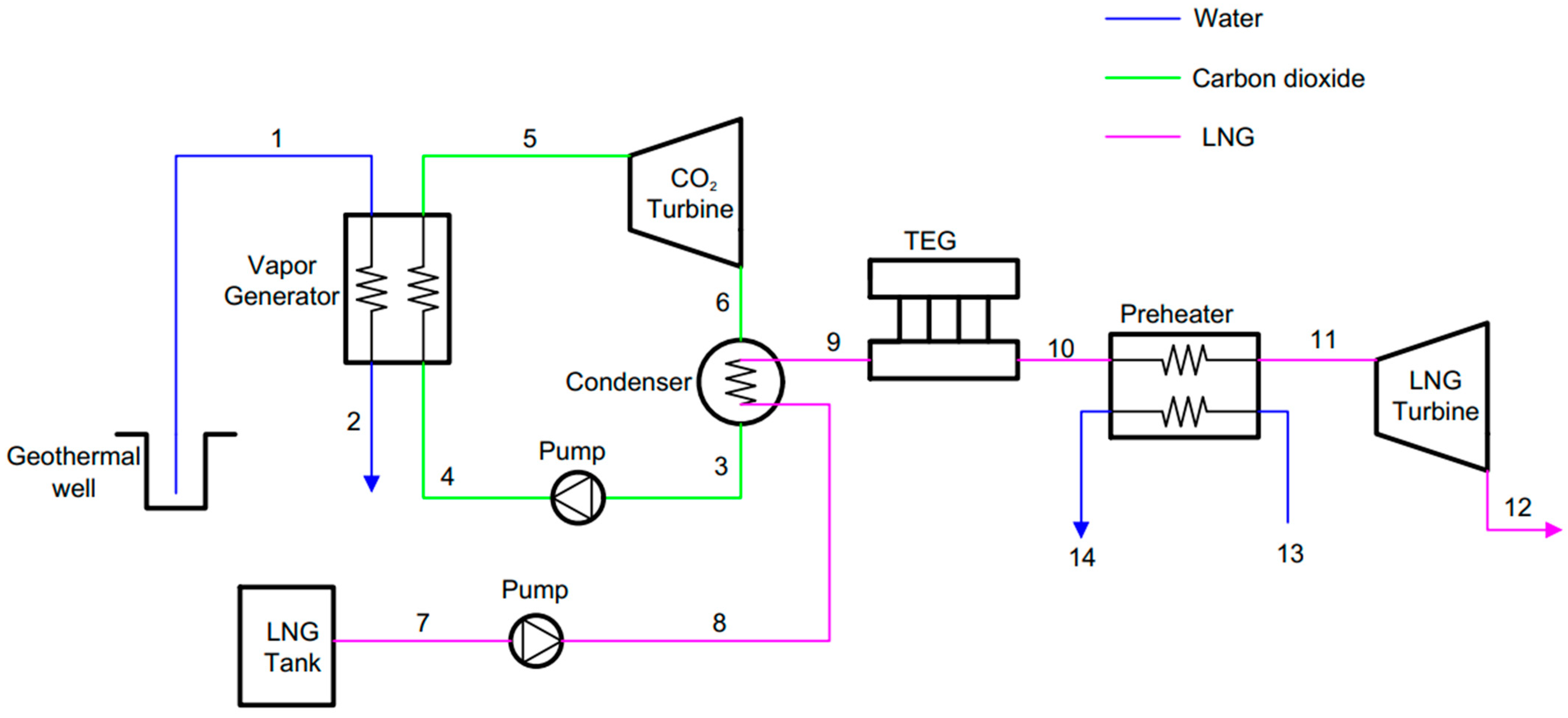
This paper presents a transcritical carbon dioxide cycle for LNG regasification, utilizing low-temperature geothermal water as the heat source. To enhance the system performance, a thermoelectric device is integrated to recover LNG cold energy. The proposed scheme is evaluated using energy and exergy analyses and compared with a simple geothermal-transcritical CO2-LNG system. To provide a deeper understanding of the system’s operational performance, a sensitivity analysis is conducted on key system parameters. Finally, a genetic algorithm is employed to optimize the system’s performance. The proposed system enhances the efficiency of LNG gasification, contributing to progress toward a sustainable future. The novelties of this paper are as follows:
A novel method is proposed to mitigate the significant exergy losses observed in conventional CO2-LNG systems by integrating a thermoelectric generator into the cycle.
Comprehensive analysis of the proposed system using both the first and second laws of thermodynamics.
Optimization of the system performance using evolutionary algorithms.
5. Results and Discussion
In this section, the simulation results are presented. MATLAB R2014a software was used to model the system, and the thermodynamic properties of the different fluids were determined by employing REFPROP [
60]. Some design values were considered during the analysis, as shown in
Table 2.
Assuming the abovementioned values, the plant can be analyzed thermodynamically. The streams’ thermodynamic properties of the proposed plant (
Figure 2) are presented in
Table 3.
Table 4 shows the most important performance indicators of the proposed system. In this table, more than half of the NOP of the system is produced by the CO
2 cycle, while the power produced by LNG and the TEG is equal to almost 30 and 20 percent of the NOP of the system, respectively. Compared to the conventional CO
2–LNG cycle, the NOP of the plant increased by 24 percent by adding the TEG.
Adding the TEG to the system also lowers the mass flow rate of the chilled water. In the conventional CO2–LNG cycle, the mass flow rate of chilled water was equal to 110.23 kg/s, while in the new, proposed plant, it was reduced to 39.61 kg/s. This is because in the new, proposed system, a part of the required heat is provided by the TEG and therefore a lower water mass flow rate is needed in the preheater. This reduces the EDR in the preheater and therefore the total exergy efficiency of the plant increases to 21.45%, while it was equal to 19.79% in the conventional CO2–LNG cycle. As can be seen, due to adding the TEG, the exergy efficiency considerably increased.
Economic analysis is beyond the scope of this paper. However, to provide context for the reader, it is worth noting that, while the cost of ORC systems varies depending on multiple parameters, it is roughly estimated to range between
$2000 and
$4500 per kW [
62]. In comparison, the cost of TEGs with a temperature difference of approximately 150 °C is around
$14,000 per kW [
63]. Nevertheless, it is important to emphasize that TEGs are still undergoing development, and advancements in their figure of merit are expected to significantly reduce their capital costs. Moreover, TEGs have nearly zero maintenance costs due to their lack of moving parts, which minimizes the risk of mechanical failures and the need for frequent maintenance [
64].
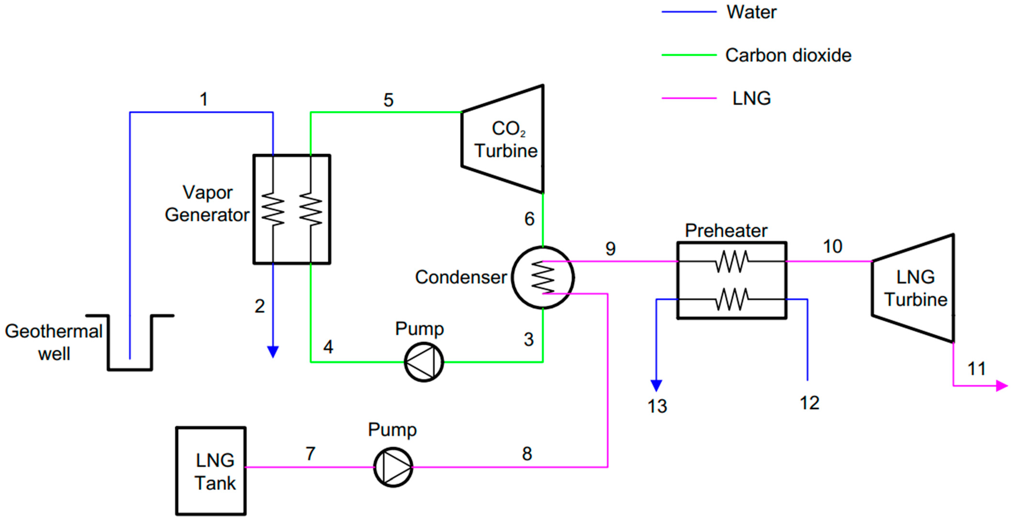
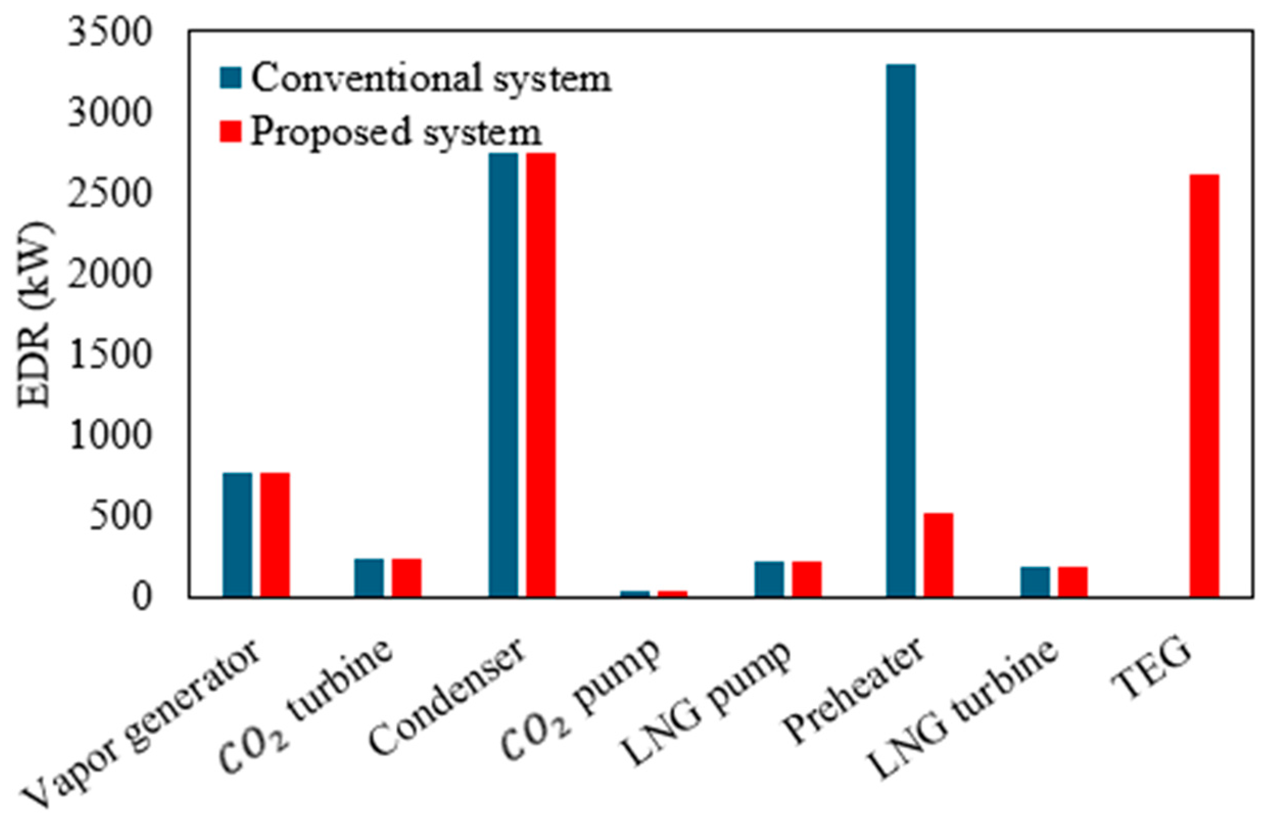
To get more insight into the exergy performance of the proposed system, the EDR of different equipment for conventional systems and the proposed system is compared in
Figure 3. As can be seen, the EDR remained unchanged after adding the TEG in all equipment except for the preheater. In the conventional CO
2–LNG cycle, the total EDR of the plant was 7534 kW. The highest EDR occurred in the preheater, where it amounted to 3301 kW, which constitutes approximately 44% of the total EDR of the plant. In the newly proposed system, the EDR in the preheater decreased significantly to only 534 kW, which now accounts for almost 7% of the total EDR of the plant. This improvement is due to the partial heat transfer being handled by the TEG, which recovers some of the energy from the LNG before it enters the preheater. However, the exergy destruction in the TEG is 2616 kW. Despite this, the overall total EDR in the new system is still 150 kW lower than that in the conventional CO
2–LNG cycle, demonstrating an improved system efficiency.
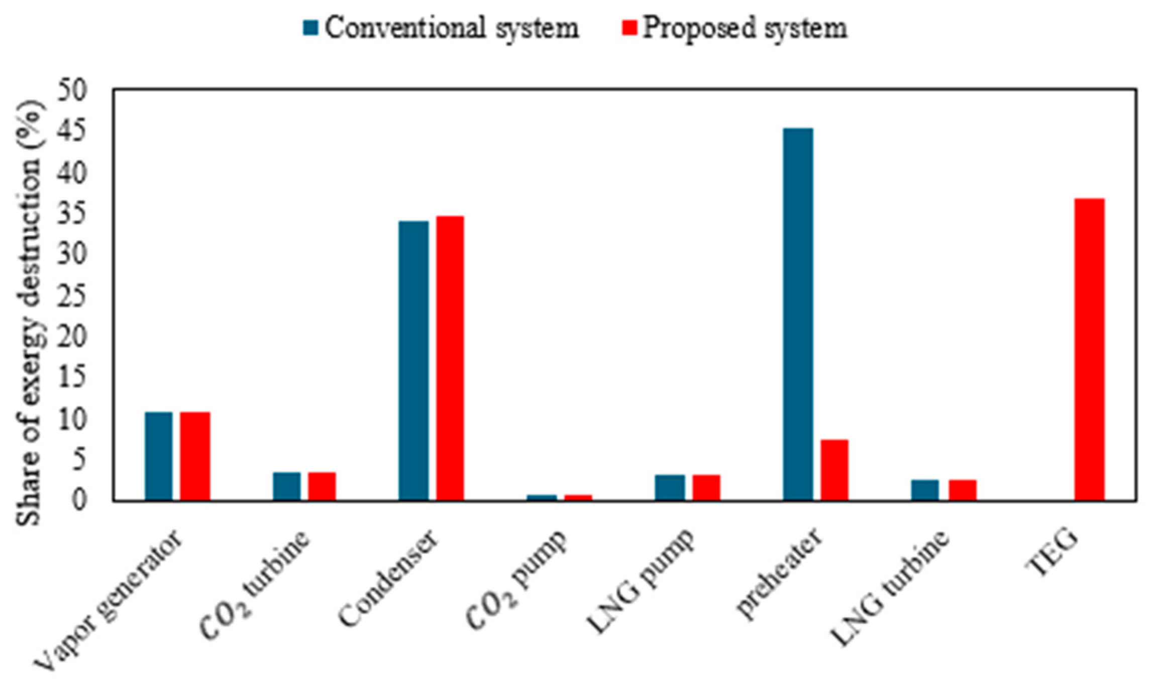
Figure 4 compares the share of each equipment in the total EDR of conventional systems and the new proposed system, which allows us to compare the performance of each piece of equipment in both systems. Although adding a TEG to the plant reduces the plant’s total EDR, the TEG still has the highest EDR among all the equipment. This is due to its low efficiency. To reduce its exergy destruction, the figure of merit of the TEG should be improved. After the TEG, the maximum EDR existed in the condenser and the vapor generator, which is due to the noticeable difference between the temperatures of the cold and hot streams of the investigated equipment.
5.1. Sensitivity Analysis
To gain a deeper understanding of the system’s performance, a sensitivity analysis is performed on different parameters of the system. To do so, only the parameter under study is changed and all the other parameters are kept constant.
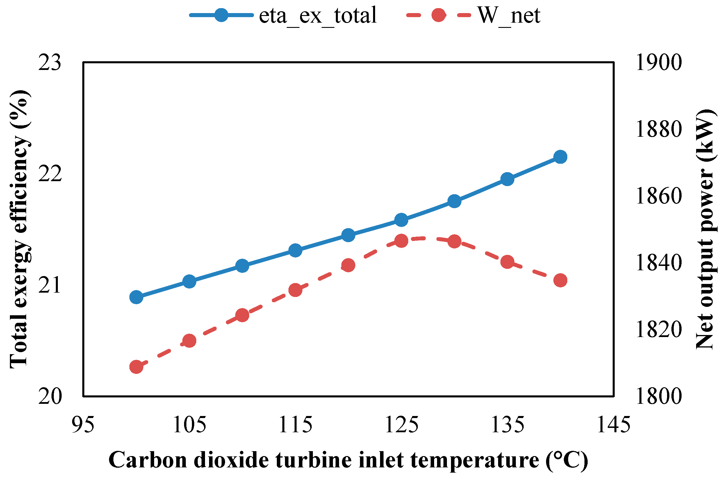
5.1.1. CO2 Turbine Inlet Temperature
The effect of the CO
2 turbine inlet temperature (TIT) on the system is shown in
Figure 5 and
Figure 6. The total exergy efficiency of the plant increases with an increasing TIT, but there is an optimal value for TIT at which NOP reaches its maximum value. When the TIT in a CO
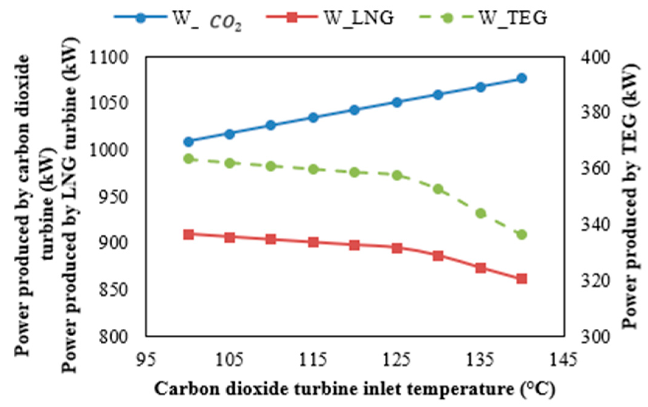
2 cycle increases, more energy is extracted from the geothermal water, but the increase in temperature results in a lower mass flow rate of the carbon dioxide. Despite this reduction in mass flow rate, the overall power produced by the carbon dioxide turbine increases, as shown in
Figure 6.
Since the mass flow rate of CO
2 decreases with an increasing TIT, a lower mass flow rate of LNG is required in the condenser, resulting in reduced power production in the LNG turbine. However, as the TIT increases, the turbine outlet temperature rises, leading to an increase in the LNG temperature at the condenser outlet. Consequently, the temperature of the cold junction in the TEG increases slightly, which reduces the temperature difference between the two junctions of the TEG, ultimately causing lower power production in the TEG. This trend is shown in
Figure 6.
Figure 5 shows that, when the TIT is between 100 °C and 127 °C, the increase in power production by the CO
2 turbine dominates, leading to a rise in the NOP with an increasing TIT. However, when the TIT exceeds 127 °C, the reduction in power production by the LNG turbine and the TEG becomes more significant, resulting in a decline in the NOP. This creates an optimal TIT for power production of around 127 °C. On the other hand, for the plant’s total exergy efficiency, there is no optimal value, and it increases continuously with a rising TIT. Although the NOP decreases beyond a TIT of 127 °C, the simultaneous decrease in the LNG mass flow rate (as explained earlier) reduces the denominator in Equation (15). As a result, the total exergy efficiency of the plant increases with a higher TIT.
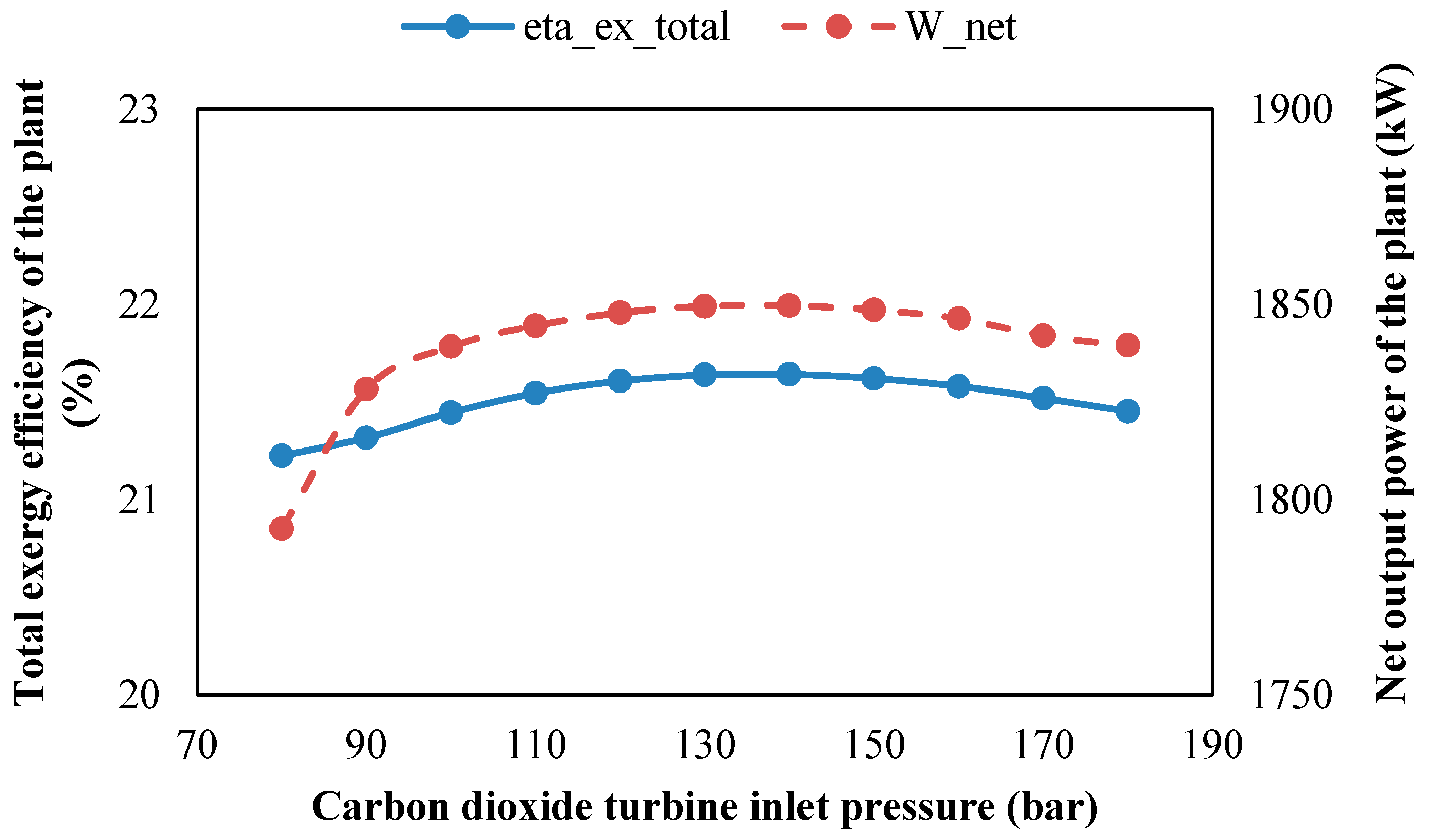
5.1.2. CO2 Turbine Inlet Pressure
Figure 7 shows the effect of the CO
2 turbine inlet pressure on the system performance. An optimal turbine inlet pressure exists, maximizing both the NOP and the total exergy efficiency of the plant. Changes in the CO
2 turbine inlet pressure have a minimal impact on the LNG cycle and the TEG, as variations in the power generation by the LNG turbine and the TEG remain below 1%. However, the CO
2 cycle is significantly affected by this parameter. Initially, as the CO
2 turbine inlet pressure increases, the rise in power production by the turbine outweighs the power consumed by the CO
2 pump, leading to an increase in the overall power produced by the CO
2 cycle. This trend continues until the NOP reaches its peak. Beyond the optimal inlet pressure, the rate of power consumption by the pump exceeds the rate of power generation by the turbine, causing a decline in the NOP. The total exergy efficiency of the plant follows a similar trend to the NOP, rising with an increased inlet pressure until the optimal point, and declining thereafter.
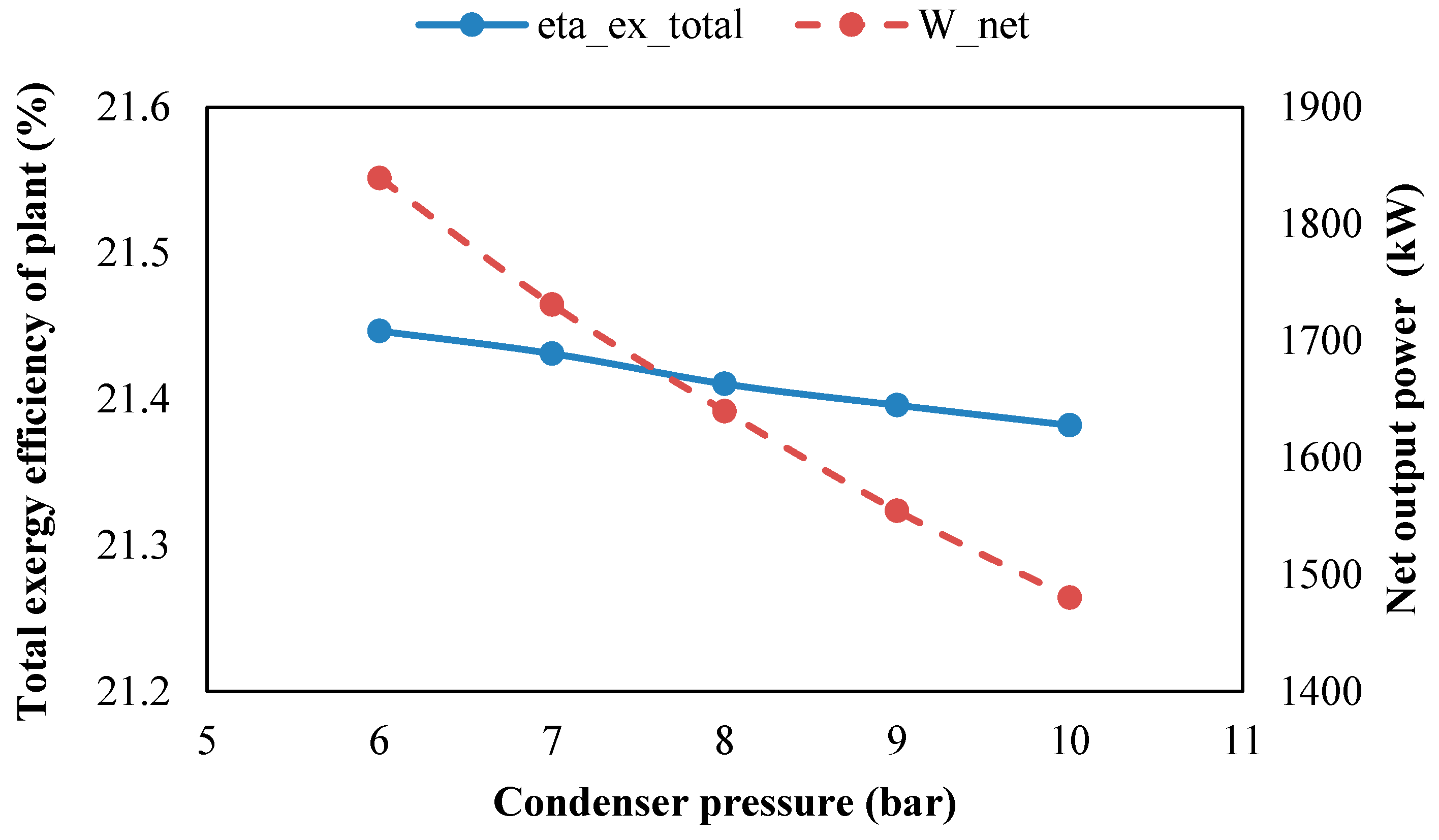
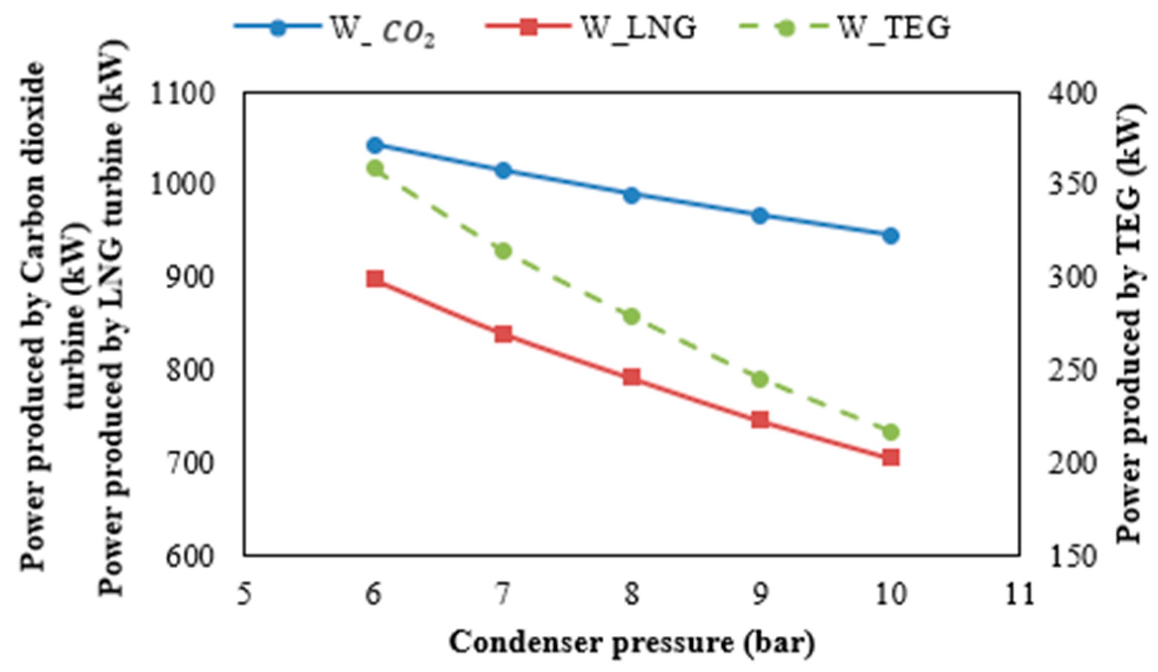
5.1.3. Condenser Pressure
The effect of condenser pressure on system performance is shown in
Figure 8 and
Figure 9. Lowering the condensation pressure increases the power production due to the increased pressure ratio in the CO
2 turbine. Conversely, as the condenser pressure rises, the pressure ratio decreases, leading to a reduced power generation in the CO
2 turbine, as shown in
Figure 9. An increase in the condenser pressure influences the mass flow rate and temperature of LNG at the condenser outlet. This, in turn, negatively affects the power produced by both the TEG and the LNG turbine.
Figure 9 shows a decline in the power production from both of these components, resulting in an overall decrease in the NOP of the plant.
The total exergy efficiency of the plant also decreases with a rising condenser pressure, albeit at a slower rate compared to the decrease in NOP. This slower reduction occurs because higher condenser pressures reduce the mass flow rate of LNG, which decreases the denominator in Equation (15). This mitigates the decline in the total exergy efficiency relative to the drop in the NOP.
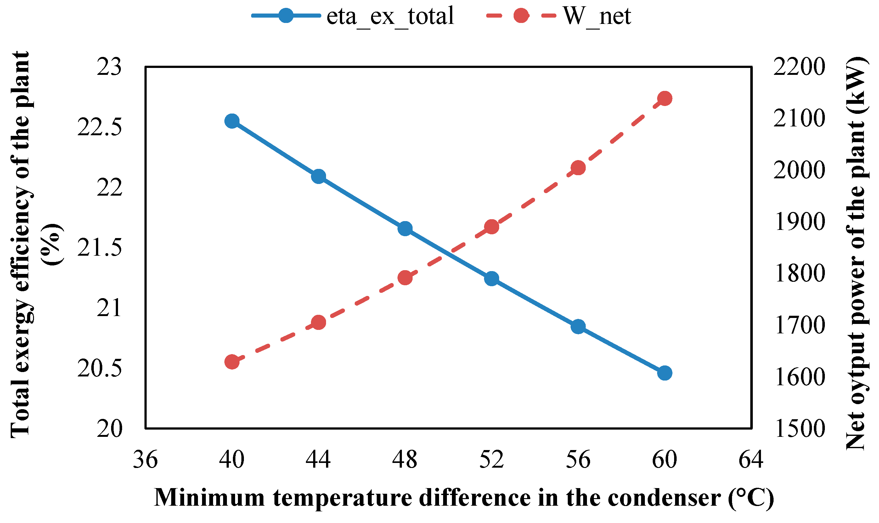
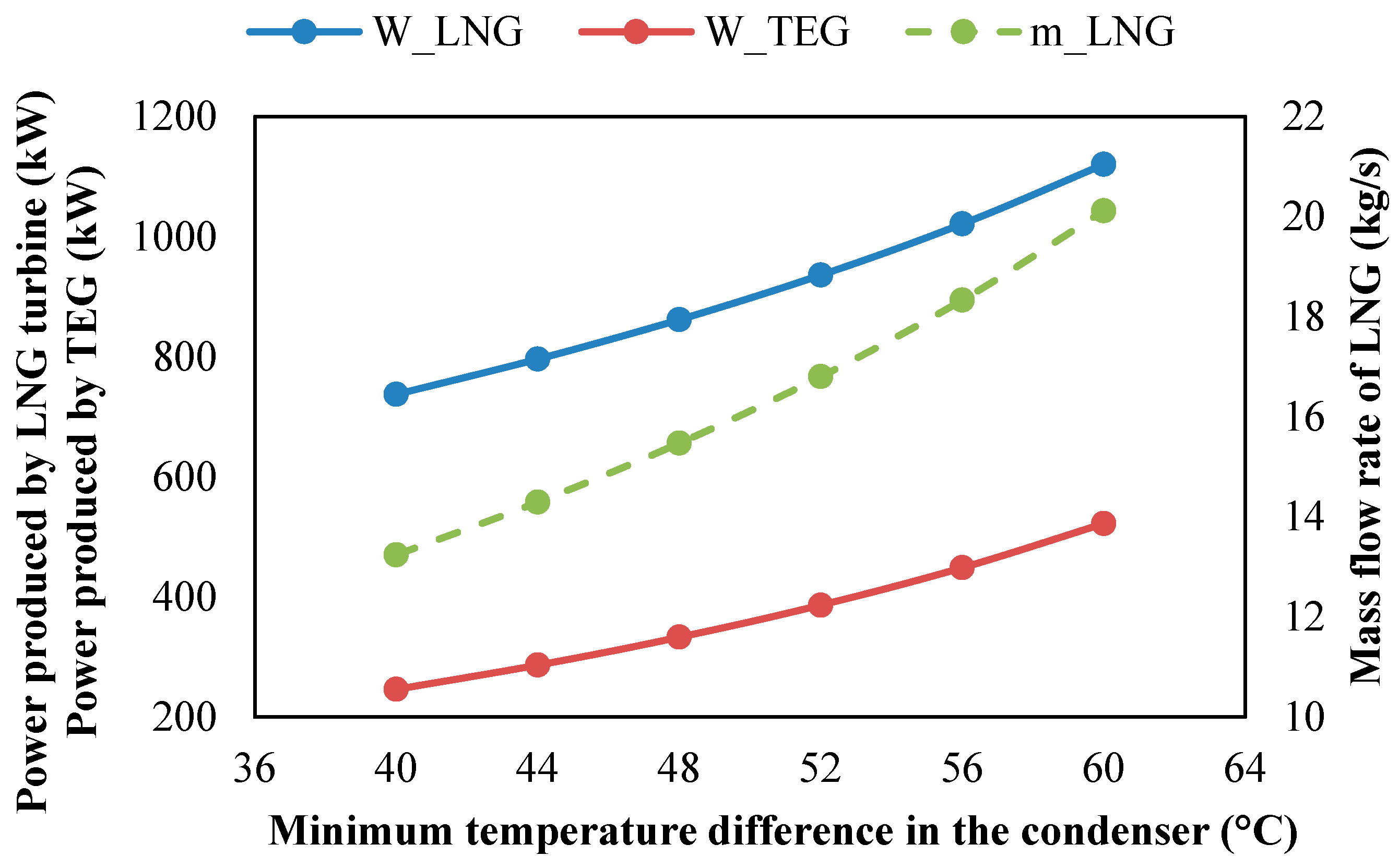
5.1.4. Minimum Temperature Difference in the Condenser
The effect of the minimum temperature difference in the condenser on the system performance is shown in
Figure 10 and
Figure 11. Changes in this parameter do not affect the CO
2 cycle but significantly impact the LNG cycle and the TEG. When the minimum temperature difference in the condenser increases, the outlet temperature of the LNG stream decreases. Consequently, the mass flow rate of LNG must rise to provide sufficient cooling energy for the condensation process. This relationship is shown in
Figure 11, where the LNG mass flow rate increases with a higher minimum temperature difference. The increased LNG mass flow rate, combined with its lower temperature, enhances power production in the TEG. Similarly, the higher mass flow rate of LNG boosts power generation in the LNG turbine. These combined effects result in an overall increase in the NOP of the plant, as shown in
Figure 10.
However, while the NOP increases, the system’s total exergy efficiency decreases with increasing minimum temperature differences. This decline is due to the increased mass flow rate of LNG, which negatively impacts the exergy efficiency by raising the denominator in Equation (15). Thus, even though a higher NOP has a positive influence, the increase in the LNG mass flow rate outweighs this benefit, leading to a reduction in the total exergy efficiency.
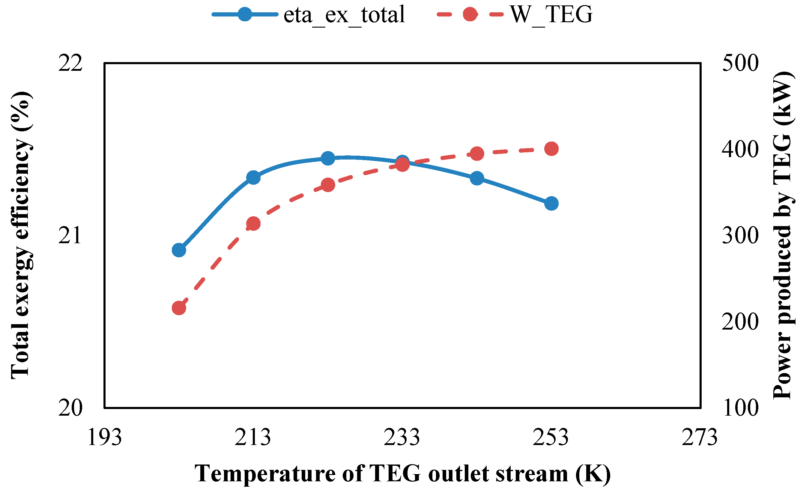
5.1.5. TEG Outlet Temperature
Figure 12 shows the impact of the TEG outlet temperature on the system’s performance. Changes in this parameter affect neither the CO
2 nor the LNG cycles; instead, they influence power production in the TEG and the cooling energy generated in the preheater.
When the TEG outlet temperature increases, power production in the TEG rises. This is because higher outlet temperatures indicate that more thermal energy is utilized by the TEG, allowing for greater electricity generation. However, the rate of this power production increment diminishes slightly as the outlet temperature increases. This trend occurs because the temperature difference between the hot and cold junctions in the TEG narrows at higher outlet temperatures.
A tradeoff exists between TEG power production and the cooling energy provided by the preheater. At lower TEG outlet temperatures, the preheater must compensate by transferring more thermal energy to the LNG, resulting in a higher chilled-water mass flow rate and greater exergy destruction in the preheater. This increased exergy destruction lowers the plant’s overall exergy efficiency. Conversely, as the TEG outlet temperature rises, power production by the thermoelectric device begins to decrease, due to the reduced temperature difference between the junctions. This reduction also diminishes the total exergy efficiency of the plant. Therefore, an optimal TEG outlet temperature exists that balances the power production and preheater performance to maximize the overall exergy efficiency of the proposed system.
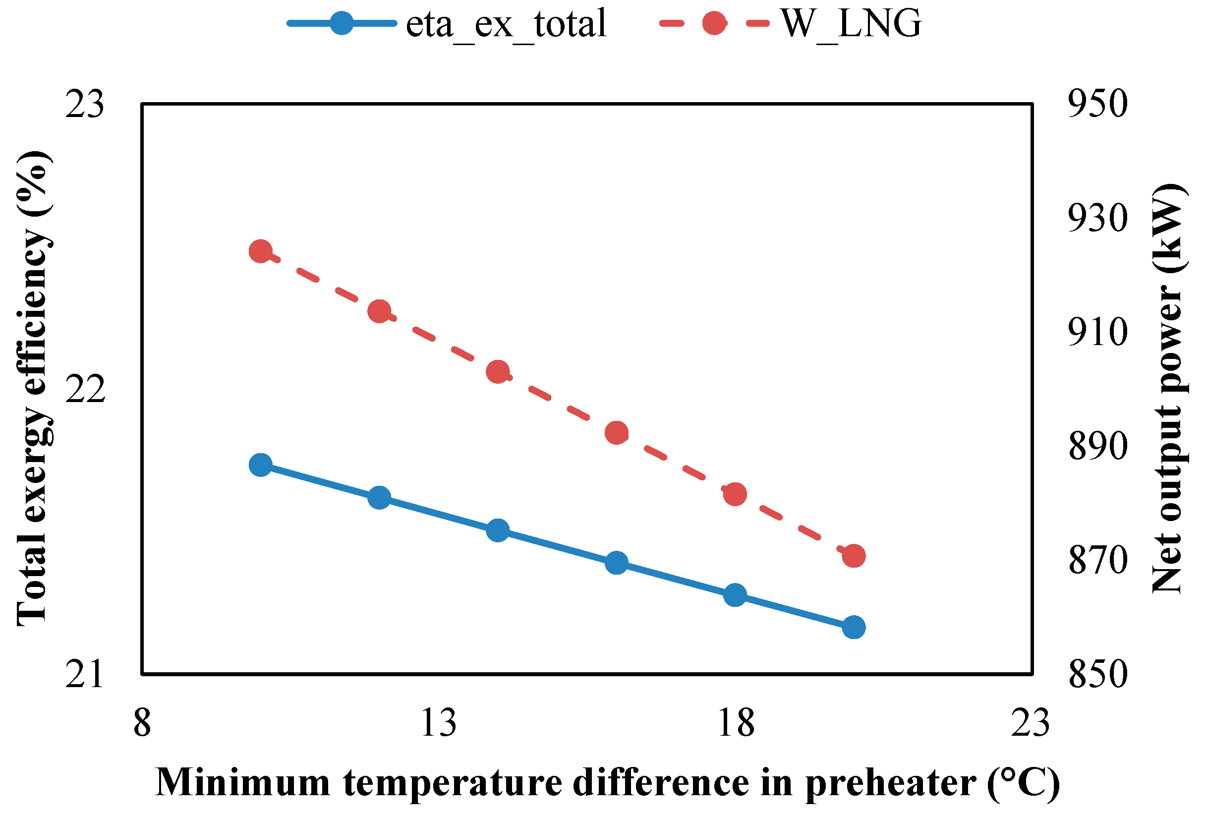
5.1.6. Minimum Temperature Difference in the Preheater
Figure 13 shows the impact of the minimum temperature difference in the preheater on the system performance. This parameter primarily influences power generation in the LNG turbine and the cooling energy produced in the preheater. A smaller temperature difference in the preheater enhances the exergy efficiency of the system. This improvement is attributed to better thermal matching between the LNG and the heating fluid, reducing irreversibilities and exergy destruction in the heat exchange process.
Additionally, power production in the LNG turbine increases as the minimum temperature difference decreases. A lower temperature difference raises the LNG turbine inlet temperature (TIT), allowing for more energy extraction during the expansion process and thereby boosting the turbine performance.
5.2. Optimization Results
To find the optimal result, a GA is employed. The optimization process takes into account six different decision variables, each with its own set of maximum and minimum bounds. These decision variables, along with their respective bounds, are presented in
Table 5. These parameters were chosen based on their significant impact on system performance, as demonstrated in the sensitivity analysis and corroborated by previous studies. Notably, all the decision variables are independent.
The optimization results, presented in
Table 6, are based on maximizing the total exergy efficiency as the objective function. As observed, the optimal values for most decision variables are either at their maximum or minimum limits, with the exception of the CO
2 turbine inlet pressure and the TEG outlet temperature. These parameters, as indicated in the sensitivity analysis section, have specific optimal values for achieving the best system performance. The maximum achievable total exergy efficiency of the proposed system is 24.11%, which represents a significant improvement compared to the exergy efficiency of the conventional CO
2–LNG cycle.
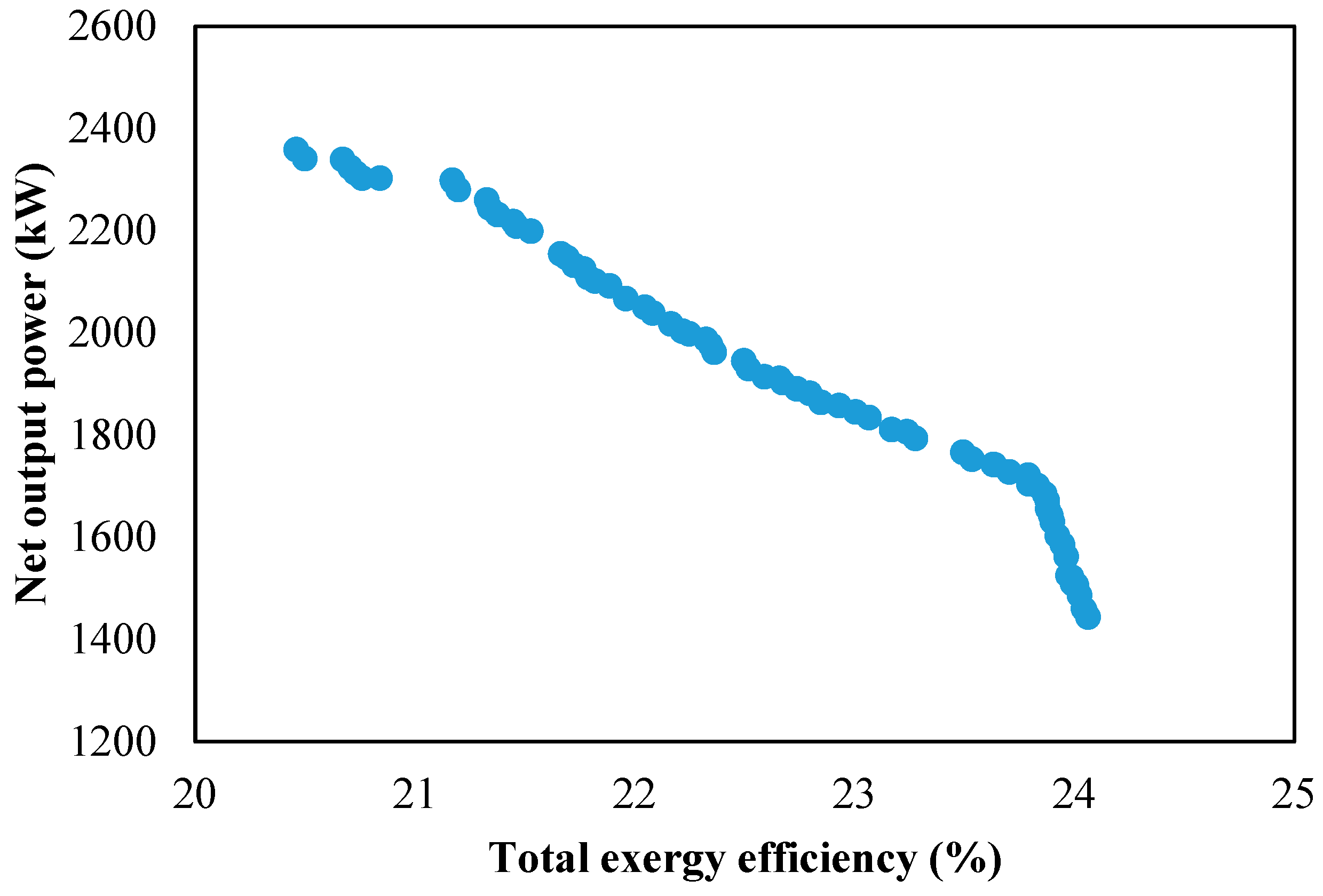
In the multi-objective optimization, where both total exergy efficiency and NOP are considered objective functions, a trade-off between these two parameters is observed. As shown in
Figure 14, there is a clear conflict between maximizing the exergy efficiency and maximizing the NOP, specifically with regard to the following:
If the goal is to maximize the exergy efficiency, the LNG mass flow rate tends to decrease. While this leads to a higher exergy efficiency, it also results in a decrease in the NOP, due to the reduced power output from both the TEG and the LNG turbine.
Conversely, if the goal is to maximize the NOP, the LNG mass flow rate increases, leading to higher power production but a reduction in the exergy efficiency due to the increase in exergy destruction associated with higher LNG mass flow rates.
This trade-off highlights the inherent balance between achieving a high power output and maintaining high efficiency in the system. The optimization process allows for identifying the best compromise depending on the desired outcomes (exergy efficiency vs. power output).


