Review

Critical Issues of Optimal Reactive Power Compensation Based on an HVAC Transmission System for an Offshore Wind Farm

1
Department of Electrical Engineering, Quaid-e-Awam University of Engineering, Science and Technology Nawabshah, Sindh 67450, Pakistan
2
Department of Electrical Engineering, Faculty of Engineering, Kafrelsheikh University, Kafrelsheikh 33516, Egypt
*
Author to whom correspondence should be addressed.
Sustainability 2023, 15(19), 14175; https://doi.org/10.3390/su151914175
Submission received: 27 May 2023 / Revised: 7 September 2023 / Accepted: 22 September 2023 / Published: 25 September 2023
(This article belongs to the Special Issue Sustainable Future of Power System: Estimation and Optimization)

Abstract

:
The reactive power (RP) control of the high voltage alternating current transmission system (HVAC TS) for offshore wind farms (OWFs) is a crucial task to assure the consistent and efficient operation of the system. The importance of RP compensation (RPC) in power system operation is to maintain voltage stability and reduce power losses. Offshore wind farms present unique challenges for power system operation due to their distance from the onshore grid, variable wind conditions, and complex electrical infrastructure. The HVAC TS is common for OWFs as it is well-suited for transmitting large amounts of power over long distances. In this paper, a literature-based analysis helps in improving the operation and reliability of OWFs, ultimately leading to greater renewable energy utilization. This paper concludes that optimal RPC is a critical task for ensuring the stable and efficient operation of HVAC TSs for OWFs. Advanced control and optimization techniques can help achieve an optimal RPC, thereby minimizing TLS and improving the overall system efficiency. Furthermore, the study investigates the possible benefits of incorporating novel technologies and approaches, such as RESs, into the power compensation process. By offering insightful information on how to optimize HVAC TSs for OWFs, for example, subsea power cables with multiple layers must be used to carry electricity from large offshore wind farms, the development of more sustainable and effective energy solutions is possible. The research concludes by stating that ensuring the steady and effective operation of HVAC TSs for OWFs is a crucial responsibility. Advanced optimization and control solutions can reduce TLS and increase system efficiency by assisting in achieving the optimal RPC.

1. Introduction

The industry’s ongoing drive for increased generating capacity to reduce project costs is the dominant trend in offshore wind turbines (OWTs) [1,2,3]. In response to market demand, all the major original equipment manufacturers (OEMs) have continued to compete to offer ever-increasing generating capacity [4], i.e., Ming Yang announced a 16-MW OWT that will go into continuous production by 2024 [5,6]. This is not only the biggest announced turbine capacity to date, but if Ming Yang can deliver on the promised timetable, it represents a significant acceleration of turbine growth in Asia as well as a significant move towards Asian and European market convergence. Fixed-bottom foundations have been used in nearly all operational offshore wind energy (OWE) installations. For example, the Global Floating and Offshore Wind (OW) pipeline increased from 26,529   M W to 60,746   M W in 2021, indicating a 34,217 MW increase [7]. Numerous recent schemes in Brazil, South Korea, Australia, and the United Kingdom have also commenced a plan for a pipeline. Offshore wind power production (OWPG) has grown significantly in recent years, particularly in Europe [8]. Presently, HVDC and HVAC configurations are being studied for offshore TS. Configurations of HVDC have typically been used for prolonged distances because RP is not produced, and power loss costs can be reduced compared to HVAC options. However, the RPC can be improved by installing mid-cable reactors [9].
While AC cables designed with greater voltages and mid-cable reactive power correction are currently being studied for longer distances, HVAC layouts are still the most common. Current projects that incorporate such mid-cable reactive power correction include Hornsea One and Two. However, the decision between HVDC and HVAC setups for large distances ought to be reconsidered [10]. A potential method to enhance the RPC is the installation of mid-cable reactors; yet, the maximum value of reactive power, or the cable loading, is decreased if the reactors are in the middle of the cables or evenly dispersed at both ends [11]. Additionally, compared to constructing a single reactor, combining reactors at both ends of the cables with a mid-cable reactor further reduces the reactive power by 25% of the maximum value [12].
Most domestic offshore wind power plants now access the land through an AC submarine cable. The large charging power is one of the properties of AC submarine cable; however, the distances from the land to the wind farm are continuously growing as OWFs are continuously built and developed. The charging power increases with submarine cable length, producing a significant amount of capacitive reactive power surpluses. However, the reactive power from capacitors causes frequency overvoltage issues to occur, which will seriously impair the equipment’s ability to operate normally. Thus, the architecture of offshore wind farms needs to be thought of with reactive power adjustment. The approach for RPC criticized in the literature can boost the submarine cable capacity, but its reactive power balancing does not properly account for the effects of changing wind turbines and 35 kV systems [13,14].
Most of the anticipated enlargement will occur offshore, wherever big wind farms (WF) have been under manufacture. The majority of these WFs will be linked to the 400   k V grids by 150   k V A C underwater cables. During steady state operation, the RP sources like switchable capacitors, FACTS, wind power reactive generation, and devices influencing RP demand indirectly such as an online tap changer should be operated to supply the highest reduction in the real power loss on the wind energy (WE) system, while satisfying the assembly grid code (GC) requirements as shown in Figure 1. When a WF is connected to a high voltage, it must meet the same criteria as any other conventional power plant. Such requirements are defined by the transmission system operators (TSO) in their GCs for corresponding levels of voltage. Because of the structure of TSO’s grid, these GCs can vary from company to company, even within the same nation [15]. Reactive power planning is an urgent issue to identify the optimal location of reactive power compensation devices [16].
The research gap in the previous studies can be summarized as OWFs are quickly expanding as a renewable energy source but numerous challenges remain to be overcome to optimize their performance and efficiency. The cost of installation/maintenance, the reliability of the power transmission network, the environmental effect of WFs, and the possibility of weather-related disruptions are among the challenges. To identify and investigate these challenges, as well as to propose innovative solutions for optimizing the performance of OWFs in terms of the cost-effectiveness of various installation and maintenance strategies, the consistency of various power TSs and the impact of weather conditions on WFs need to be studied. The expansion of OWFs represents a promising answer to meet the global energy demand; however, the HVAC TSs for these WFs present challenges in terms of the environmental effect, cost, maintenance, reliability, and weather conditions.
Despite these obstacles, it is critical to ensure that OWF electricity is delivered to the grid with stability and high efficiency. This paper intends to explore the best power compensation strategies to overcome these issues and enhance the system performance and efficiency of the HVAC transmission system in offshore wind farms. The study’s objective is to assess the effects of various power compensation methods on the stability, expense, dependability, and environmental impact of transmission networks. Furthermore, the study will investigate the possible benefits of incorporating novel technologies and approaches, such as RESs, into the power compensation process. By offering insightful information on how to optimize HVAC TSs for OWFs, the authors of [16] elaborate on the development of more sustainable and effective energy solutions. Subsea power cables with multiple layers must be used to carry electricity from large offshore wind farms. PE cables are preferred to impregnated paper insulation due to their high conducting temperature, lack of moisture barriers, and simple union method.
This paper is concerned with the reactive power control of high voltage alternating current transmission systems for offshore wind farms. The literature-based analysis of this study could be useful for improving the operation and reliability of OWFs, ultimately leading to greater renewable energy utilization. The paper concludes that finding the optimal RPC is a critical task in ensuring the stable and efficient operation of HVAC TSs for OWFs.
The main contributions of this review-based study can be summarized as follows:
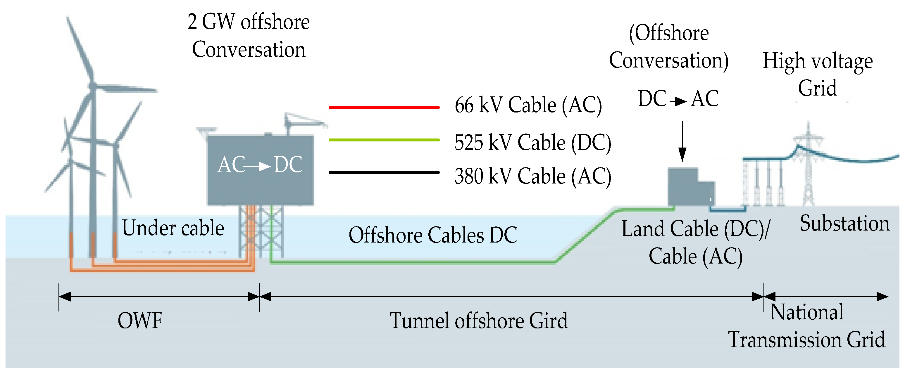
  • A presentation of the layout of HVAC transmission systems and their associated configurations.
  • A discussion of the concept of reactive power compensation methods.
  • As this study is concerned with the technical issues that appear with the stability problem of OWFs, the voltage stability problem is discussed as well as methods for its improvements.
  • A review of various optimization methods that have been developed to find the optimal scheduling of reactive compensation devices in power systems.
  • A cost-based assessment study is provided.
  • Finally, the main challenges are reported to open an era for future research.
This paper is organized as follows: Section 2 presents the layout of the high voltage alternating current transmission system and Section 3 presents the reactive power compensation analysis. Section 4 presents some technical issues about the stability of OWF, Section 5 is concerned with the voltage stability improvement and the associated control techniques, Section 6 records the optimization techniques that were used to find the optimal scheduling of the reactive power compensation problems, Section 7 presents the economic assessment of the RPC problem, Section 8 concludes the challenges of RPC problems, and, finally, Section 9 concludes the main findings of this study.

2. High Voltage Alternating Current Transmission Systems

Figure 2 presents an overview of an OWPP. HVAC TSs are used in many OWF links; however, due to the high losses and expenses associated with using AC transmission for long distances, in recent years, the use of such a system has declined. This is primarily due to the RP produced in the cables, which rises with the square of the alternating current voltage and cable length. These restrictions of the active power can be conveyed throughout the cables, and, thus, the cable length in offshore applications, which explains the high expense and trouble of installing RPC units along submarine cables [18]. However, compensation units have a very limited impact and can only be placed at the ends of the line in offshore transmission applications.
One option is to operate the electrical system at a low frequency. This necessitates additional frequency conversion equipment as well as reactors and larger transformers; however, this is hard to execute offshore due to the large platforms required as well as the high costs involved with such an approach. Another solution proposed is to use more than three phases, yet this is equally impractical in offshore applications due to the limited amount of cable available [19].
The configuration proposed consists of two substations joined together by anode-linked polyethylene cables. The power transformers, air-insulated or gas switch gears, and RPC devices are all part of the substations illustrated in Figure 3 [20]. Offshore transformers are then used to increase the power from an OWPP’s collector grid from 33   k V or 66   k V to a transmission level of 110   k V ,   150   k V ,   a n d   220   k V [21]. Onshore transformers are used to increase the voltage to the working level of the onshore grid (220–400 kV). To increase power export availability, the recommended transformer topology is two parallel transformers rated for nominal power for OWPP at 66 % . Depending on the transmission voltage and rated power of the OWPP, several cable lines are linked in parallel. In addition, reactors are used along the cables for RPC, which reduces power losses and gives additional voltage control [22].
A VSC HVDC-based topology built on a symmetrical mono–polar configuration is used in TS and is shown in Figure 4 [9]. This arrangement comprises two VSCs linked by DC transmission cables measured for 525   k V . Transformers link the converters to the respective AC side. These VSC converters connect the HVAC and HVDC systems by utilizing devices appropriate for high-power electronic applications (HPEA), like IGBT. The VSCs can self-commutate, meaning they can produce alternating current voltages without the need for an alternating current system [23].
Figure 2. OWPP overview [20].
Sustainability 15 14175 g002
Figure 3. HVAC TS [9].
Sustainability 15 14175 g003
Figure 4. HVDC TS [9].
Sustainability 15 14175 g004

3. Reactive Power Compensation (RPC) Analysis

Figure 5 depicts the correspondent circuit of the investigated system for investigating the RPC. The compensating unit is situated at the load end which addresses the issue of sizing the compensator’s capacity. With a certain value of R L o a d , we obtain an invariable value of I L o a d , which is also the cable output current, because the estimation of the algorithm assumed that a constant voltage is kept at load junction. The entire estimate process is then examined; the cable input current I i n is reduced by installing the shunt reactor (SR) at the load junction. Thus, the cable can convey extra active power at the cable’s end load by changing the positioning of the SR. The load end of the cable is put onshore for power transmission from an OWF to an onshore PS because the maintenance, installation, and operation of the SR are simpler onshore. Nevertheless, it should be mentioned that the fixing of compensating devices in this scenario has the vital role of maintaining an allowed voltage profile as well as boosting the cable’s transferable power. As a result, when an OWF is interconnected, compensating units are placed on both sides of the cable [24]. Figure 6 depicts the RPC requirements for delivery networks, while Figure 7 depicts the RPC requirements for TNs. The VDEW procedure unifies the p.f. but the final choice is left to the network company in charge of network integration [25].
The requirement for RPC is revealed through the Swedish regulations (SvK) conditions for an acceptable voltage range. Large > 100   M W and medium-sized 20 50   M W WFs must be able to sustain automatic RPC with a reference voltage value [26] and the reference number must be adjustable to within 10 % of the nominal operating voltage. A similar condition is mentioned in the Sintef system for all WFs linked to voltage levels greater than 35   k V . The upper limit allowed for a voltage increase from a WT at the PCC is also defined by “the research institute for Danish electric utilities (DEFU)”, VDEW, and AMP, which for the DEFU is 1 % , VDEW is 2 % , and AMP is 2.5 % [27].
According to the technical rules for connecting WFs to electricity systems, the RPC should be set using the hierarchical and regional balance principles. For OWFs, the submarine cable’s charging power should be balanced by setting the inductive power compensation device [28]. Due to excessive RP losses, RP cannot be transmitted over lengthy distances or through power transformers. Thus, the RP supply should be placed near the consumption [29]. In the maximum and minimum load modes, the layer-partition balance of the RP is achieved as the state of equipment maintenance and failure [30].
Figure 5. Equivalent test system circuit in shunt reactor at the load end Z C o m p with stable state [27].
Sustainability 15 14175 g005
Figure 6. Requirements for reactive electricity.
Sustainability 15 14175 g006
Figure 7. Requirements for a Vestas V80 2MW turbine in terms of the RP and technical issues.
Sustainability 15 14175 g007
The RPC device should be centralized as much as feasible so that the compensation devices can be managed and inspected on time. Parallel capacitors can also be configured in a reasonably decentralized manner, but too much dispersion will cause maintenance and management issues [31].
  • Reactive power should not be sent over long distances via the transmission line to the desired destination to increase the power quality and lower power loss.
  • The layer-partition balance of reactive power must be attained in the mode of maximum and minimal load operation, and the maintenance and failure status of the equipment must also be considered.
  • To prevent the power grid from seeming to have an inadequate supply of reactive power in the case of equipment failure, it is necessary to create an equipment maintenance or fault condition reactive power budget and to prepare matching steps in advance [32].
The RPC for substations primarily fulfills the demand for distribution transformer RP capacity. The following factors for reasonable compensation can be referred to in the specific compensation principles [33].
i.
Principle for compensating reactive power at a medium voltage (10 kV)
Low-voltage individual compensation, dynamic reactive power compensation, and high-pressure concentrated compensation should all be included in medium-low voltage grid reactive power compensation. The low-voltage side of the centralized compensation design of the distribution transformer should be prioritized, and then the high-pressure side of the dispersion compensation should be taken into consideration as a helper. In general, shunt capacitors are set up to enhance the power factor. Shunt capacitor configurations might range from 20% to 40% of the primary transformer’s capacity [33].
ii.
Principle for a medium and high voltage reactive power adjustment (35 kV to 110 kV)
The load of the line will typically be greater than the natural power in the 35 kV–110 kV power grid. The appropriate substation should distribute the grid because it is inductive. The capacitive compensating devices’ capacity can then be set between 15% and 30% of the main transformer’s capacity [33].

4. OWF Technical Issues

One of the network operators’ principal concerns is how to grid can be ensured and maintained within stable operation [34]. To ensure dependable PS operation, strategies for maintaining the stability of a PS with high wind power penetration are required [35]. Wind farms that connect to the electrical grid create RP redistribution and variations which can lead to voltage fall. Distribution network operators must confront the significant challenges due to the voltage variance caused by changing dynamic VS and wind generation [36]. Wind power generation units differ significantly from classic dominating power plants fitted with synchronous generators (SGs) controlled by AVRs and PSS. These control systems may assist the PS in improving the voltage performance when system parameters change, such as when there are incremental changes in the voltage fall or system load due to a modest rise in the demand for RP in the system [37]. Large wind farms must be run like conventional power plants with SGs, just as GC specifications. The WTs in OWFs with DIFGs and long HVAC cable connections to the grid can be operated in both the over-excited and under-excited quadrants by employing an appropriate control approach. This implies they can either consume or give reactive electricity to the grid. They have similar characteristics as SGs; as a result, the voltage can be controlled within a specific range. Furthermore, by using dynamic Var compensation units, quick voltage regulation is achievable [38].
Given the grid connection of huge OWFs via long HVAC cables that may generate over-voltage issues, the VS issue may grow severe and should be thoroughly investigated. Some TSOs have amended their GC and imposed stringent standards for wind farm voltage performance under low voltage contingencies, known as low voltage ride-through capability. This means that the WTs should be able to assist the system in recovering when the voltage dips in an emergency, without causing voltage instability. In fact, symmetrical faults are the riskiest power grid emergencies. As a result, the VS studies of large OWFs should be conducted using disturbances such as three-phase short circuits [39]. Additionally, when it comes to the wind farm model that will be utilized for VS analysis, several pieces of research demonstrate that aggregated or simplified models can produce misleading results for voltage problem studies, such as low voltage rides. The full and complete fifth-order model should be utilized to obtain more trustworthy results for the dynamic VS assessments of OWFs in a real grid [40].

5. Voltage Stability (VS) Improving and Control Techniques

RPC is frequently the most effective method of improving both the VS and power transfer capability. Managing voltage levels is performed by managing the RP output, absorption, and flow. Generator units provide basic voltage management because automated voltage regulators (VR) control the field excitation to sustain the arranged voltage levels at the terminals of the generator. However, further devices must be utilized to compensate for the RP to manage the voltage across the system [41]. Reactive compensation is classified into two types: series and shunt compensation devices. It can also be classified as passive and active compensation. However, the majority of attention will be placed on static var compensators and STATCOM, which are all part of the flexible AC transmission systems (FACTSs) category of active compensators [42].
SCs are reasonably priced to install and maintain. Installing SCs in the load area or where they are required can improve the VS. However, shunt capacitors suffer from poor voltage control, and beyond a certain amount of compensation, a steady working point is impossible to achieve. Furthermore, the SC RP is related to the square of terminal voltage; under low voltage circumstances, Var support reduces, compounding the problem [34,43]. Installing capacitors in weak buses is a frequent practice in PSs to increase the VS, power factor, and bus load ability, and thus reduce power and energy losses. Because of the economic and technical benefits connected with the installation of capacitors in PSs, the use of SCs has risen. A sensitivity analysis on the RP of every bus is achieved to identify the position of the shunt capacitor [44]. Figure 8 depicts the SC model connected to each bus. A SC switch is arranged in line with the required RP. There are a total of seven patterns that this shunt capacitor can switch between: 0.0, 0.2, 0.4, 0.6, 0.8, 1.0, and 1.2 pu. For instance, when Q C is 0.92 pu, QC equals 0.8 pu, and when Q C is 1.1   p . u , QC equals 1.1   p . u . This pattern is related to the reactive power index Q during the voltage collapse steady condition of transmission line 2 [45].
Figure 9 depicts the conceptual framework of a shunt capacitor control approach that employs a VS margin. The needed RP quantity threshold value Q C is calculated as the difference between the VS margin Q b e f of the steady-state RP and the VS margin Q a f t   of the current-state RP [46]. The shunt capacitors’ Q′C reactive power need is calculated as.
Q C Q b e f Q a f t
where the indications of the transmission line with the worst voltage stability are Q b e f and Q a f t .
The STATCOM is a shunt-connected RPC appliance that can generate or absorb RP whose output can be changed to manage certain system characteristics. When fed from an energy storage apparatus at its terminals of input, it is a solid-state switching converter capable of generating or absorbing independently regulated real and RP at its terminals of output. A STATCOM is an RP source that can be controlled [47], it generates and absorbs RP exclusively through the electronic processing of the current and voltage wave patterns in the VSC. Figure 10 depicts a single-line STATCOM power circuit in which the VSC is magnetically coupled to a utility bus.
The STATCOM is depicted in Figure 11 as a variable voltage source concealed beyond a reactance, involving capacitor banks and SRs that are not necessary for RPG and assimilation, resulting in a solid plan with a magnetic impact, small footprint, and low noise [16,48,49]. STATCOM enhances the power system performance by:
  • The distribution and transmission of the networks’ dynamic voltage control.
  • Dampening of the power-transmission systems’ power oscillation.
  • Controlling voltage flicker.
  • Controlling both reactive and, if necessary, active power in the associated line, which calls for a DC energy supply.

6. Optimization Technique for Reactive Power Compensation

Meta-heuristic algorithms can solve any issue and offer a globally optimal solution. Algorithms are usually nature-inspired methods that can be classified as bio-inspired algorithms, chemistry-based algorithms, and physics-based algorithms [49,50,51]. While the bio-inspired algorithms are classified as swarm-based, evolving, and plant-based Intelligence.
Evolutionary algorithms are random population-based meta-heuristic optimization types. The algorithm progress is inspired by reproduction, mutation, selection, and recombination, so the optimization problem can be iteratively solved by developing a population of solutions, with the best individuals passing on to the next generation until the termination criteria are met. Evolutionary algorithms include evolutionary programming, genetic algorithms, genetic programming, and evolutionary strategies and are widely used in the literature to solve RP optimization issues [52,53]. To obtain the greatest economy of RPC for the HVAC transmission system of an OWPP while satisfying all GC principles, compensation sites and capabilities must be optimized [54]. The further power loss gain reduces the extra cost of the offshore stage due to the established RPCs and must be included when examining the compensation proposal of the HVAC gearbox of OWPPs [55]. The object optimization can be written as [56]:
C = C T P ˙
C T = C l o s s   o f   l i n e + C l o s s   o f   c a p a c i t y + C C o m p e n s a t i o n
C l o s s   o f   l i n e = P ˙ P ¨ T P
C l o s s   o f   c a p a c i t y = 1 C o s θ 1 P ˙ T P
C C o m p e n s a t i o n = 3 Q 1 C u n i t   o f   o f f s h r e   + 3 Q 2 C u n i t   o f   o n s h o r e T l i f e
HVAC transmission systems with RPC must adhere to several restrictions, including p.f constraints at both cable ends, cable transmission uniqueness, and the highest current constraints [57].
U ^ 1 I ^ 1 + j Q 1 U ~ 1 = C o s θ Z ˙ C S i n θ S i n θ Z ˙ C C o s θ U ^ 2 I ^ 2 j Q 2 U ˇ 2 θ U ^ 2
Table 1 highlights the papers with the closest approximations to the actual topic and those that have been updated in the discussion of this problem are in [58].

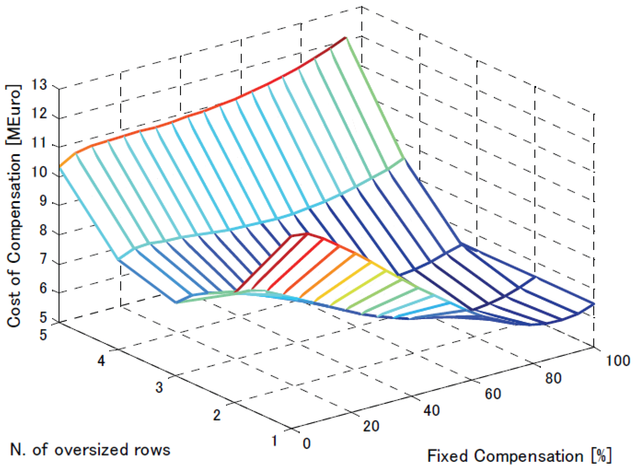
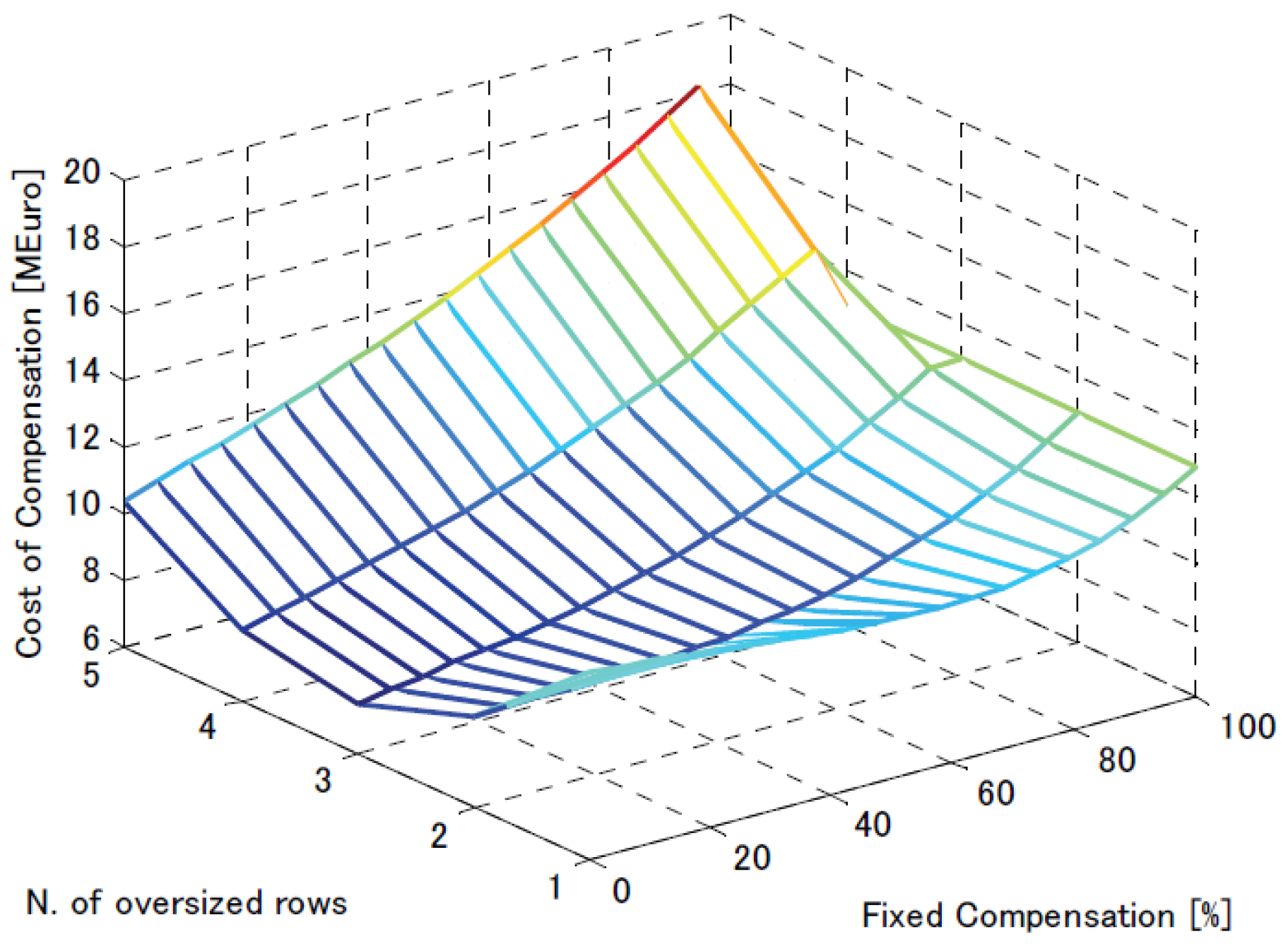
7. Cost Analysis of HVAC OWFs

OWFs and their distance from shore make it possibly more cost-effective to switch to HVDC PT to surmount the intrinsic constraints of AC cables. However, DC TS approaches have a significant rise in interest costs due to the massive structure that must be built offshore for an AC–DC converter station [72,73]. Even though HVDC technology has advanced rapidly in recent years, and solutions that are suitable for offshore exploitation are being developed, their costs are not decreasing and may rise in the near future because of the large number of intended schemes and the very incomplete number of providers of similar technology. Therefore, it is critical to maximize the ability of traditional HVAC TS with underwater AC cables while restraining the use of HVDC to severe TSs where the enlarged controllability and the lack of synchronization issues are critical [74]. The cable length of an HVAC transmission line is an essential element because the entire transmission of electric power from offshore to onshore is dependent on it. Thus, the price of the cable length is proportionate to its length; as the length or distance increases, the expense of the material used to make the cable increases [75]. Aside from that, the cable length material should be strong and comprised of many protective layers as it transmits underwater, so the cost of cable length can also be affected by the desire for protective layers. In addition, the voltage level of the HVAC TL can have an impact on the expense of the TS as the thickness and expense of cable insulation can rise as the voltage level increases [76].
The installation method required for the TS has an impact on the overall cost. As these methods include plowing, trenching, or drilling, the cost varies depending on seabed conditions such as water depth and distance to the onshore grid. Figure 12 depicts there are two fundamental techniques for offshore RP injection:
  • A rigorous cost is achieved by placing a devoted reactor on the collection station, to which the sending end of the HVAC cable is attached.
  • A dispersed cost is achieved by utilizing the PE connections of the generating units (GU). Every method adds to the total equipment cost in a different manner.
One apparent method of injecting inductive RP at one cable end is to place a three-phase stable inductor immediately after the offshore step-up transformer.
Since the transmission voltage remains constant, the amount of RP held by the cable remains basically stable, making fixed compensation very advantageous. In terms of investment, connecting a specified compensating inductor to the park will result in two expense items: the self-inductor expense and the additional cost of the offshore group stage because of the inductor’s addition.
A magnetic component’s cost, such as a compensating inductor, is generally proportional to its rated RP capacity, Q F [77]. The cost dependency is nonlinear, and the following exponential cost function is computed using data from multiple producers and a regression method.
C L F = X L F + Y L F Q F V A C L F
It is reasonable to presume that an offshore reactive compensation stage is already managed because the transformer is used as a step-up for the HVAC connection to the shore. What must be considered now is the extra cost of a stage as a result of the CR. Overall, for a known cost function of the accessible stage “ C P l a t f ”, the added cost can be T r a n s and conveyed by a linear estimation, assuming that the added weight because of the compensator “ A L F ” is suitably less than the unique LF loading of the stage “ A T r a n s ” [78].
C P l a t f = d C P l a t f d A A = A T r a n s A L F
In [79], the authors calculate the density of a distribution transformer (DT) based on its basic impulse insulation level (BIIL) and VA grade.
A k g = 6 k V A 0.8 B I L k V 0.3
Expanding such a calculation to include inductors with like Var ratings and a supposed 230   k V level of voltage with a related BIIL of 800   k V , the cost function for the stage is:
C P l a t f = 20.6 . 8 0.3 Q F k V A 0.8
Thus, the expense of an offshore stage has been approximated as an elementary linear function of the amount of installed VA.
C P l a t f = 0.08 Q F [ V A ]
Figure 13 depicts the cost calculation differences between Equations (4) and (5). The large disparity may be clarified by supposing distinct platform technologies. Both estimates will be used next to demonstrate the optimal solution’s dependence on the site’s exact circumstances [77]. Furthermore, in Figure 14, a comparative analysis has been presented between the cost and fixed reactive compensation. The steps of the cost are divided on a scale from 0 to 10, whereas the scale for the fixed reactive power compensation is divided from 0 to 150 MVAR.
As seen in Figure 13, the cost of HVAC OWFs has increased with respect to fixed reactive compensation. Also, the cost of the electricity transmitted and the amount of power lost both rise as T P rises. Equations (11) to (12) were used to analyze the reactive compensation cost of the distributed injection for a distinct number of oversized units which is presented in Figure 13. The specialized reactor generates the largest proportion of the compensatory reactive power, whereas only a small number of units have a slightly bigger converter/transformer. The number of large units depends on the layout. Figure 15, however, shows that it is primarily influenced by the offshore collection platform’s very low cost. Results might differ if a more expensive technology is applied, for instance, because of deeper water or the presence of more severe waves and tidal environments. Figure 15 illustrates the cost profile when the incremental cost of the platform is calculated using Equation (12), which demonstrates this aspect [80].

8. Challenges for Optimal RPC in OWFs

The above study identified a model to improve voltage stability and highlights several significant problems that have persisted as research challenges in the RPC field. By coordinating available voltage and reactive power control devices, such as on-load tap-changers, substation shunt capacitors, and feeder shunt capacitors, the steady state voltage and RPC in distribution systems can be effectively regulated. Reactive power and voltage stability in the transmission, distribution, and load were briefly discussed, as well as the significance of the local provision of reactive power. The explanation of a few shunt power system controls, including SVC, static reactive power compensators, STATCOM type systems, static reactive power generators, and systems that combine both solutions, known as SVC, is based on STATCOM [77,78,79,80,81,82]:
  • The proper selection and coordination of equipment for controlling reactive power and voltage stability are among the major challenges of power grids [78].
  • Long-distance power transmission has several technological difficulties in addition to greater installation costs as one moves further from the shore [80].
  • The weight of the turbine nacelle, which normally houses the generator, converter, and grid-side step-up transformer, as well as the monitoring and control equipment, presents a barrier when establishing wind farms. A 5 MW turbine nacelle weighs roughly 300 t, whereas the rotor is only about 120 t. Installation at an offshore wind farm often accounts for 20% of the capital costs, which is considered extremely expensive [83,84].
  • Enhancing the voltage stability of the AC–DC microgrid is considered in [85] for voltage control. In that paper, a fuzzy logic base was provided for designing the PID controller to boost the dynamic power quality performance. In [86], a fuzzy-based controller was proposed for improving the voltage stability in an AC–DC micro-grid associated with D-STATCOM

9. Conclusions

To summarize, optimizing the RP control of an HVAC TS is a critical task for OWFs to guarantee reliable and efficient operation. RPC’s significance in maintaining VS and lowering TLs has been discussed. Various control techniques, including advanced and conventional techniques, have been examined, and it has been demonstrated that advanced control and optimization techniques can aid in the achievement of optimal RP compensation. A comparison of different optimization techniques, such as meta-heuristics, has been given. Advanced control and optimization techniques can greatly improve the performance of the HVAC TS for OWFs, lowering costs and increasing the system efficiency by 0.34%. However, more study is required to investigate how these techniques perform in real-world OWF applications. Overall, determining the optimal RPC of an HVAC TS for an OWF is a difficult job, but it is achievable using advanced control and optimization techniques, guaranteeing the system’s stable and efficient operation.
To improve the current distribution and reduce the power loss of an HVAC cable in an offshore wind power station, reactive power correction is typically needed. While compensation at the onshore end of the cable is primarily used for power factor correction at the grid connection point, compensation at the offshore end of the cable can successfully realize these two purposes. The cost of the reactive power compensation equipment itself as well as the HVAC cable’s power transmission capacity, which determines the power loss through the cable and affects the economic compensation capacity, should be considered to achieve the best economy of reactive power compensation. The research concludes that ensuring the steady and effective operation of the HVAC TS for an OWF is a crucial responsibility. Advanced optimization and control solutions can reduce TLS and increase system efficiency by assisting in achieving the optimal RPC.

Author Contributions

Conceptualization, methodology, A.R. and M.A.K.; formal analysis, Z.A.; investigation, A.R., M.A.K., M.J. and R.A.E.-S.; resources, R.A.E.-S.; writing—original draft preparation, M.A.K., Z.A. and M.J.; writing—review and editing, M.A.K. and R.A.E.-S.; visualization, supervision, M.A.K. All authors have read and agreed to the published version of the manuscript.

Funding

This research received no external funding.

Institutional Review Board Statement

Not applicable.

Informed Consent Statement

Not applicable.

Data Availability Statement

Not applicable.

Conflicts of Interest

The authors declare no conflict of interest.

Abbreviations

ACAlternating currentPCCPoint of common coupling
CSCCurrent source convertersVSCVoltage source converters
DCDirect currentRESRenewable energy sources
DEFUResearch Institute for Danish Electric UtilitiesWTWind turbines
HVACHigh voltage alternating CurrentWFWind farm
OWFOffshore wind farmWEWind energy
OWTOffshore wind turbinesRPCReactive power compensation
OWEOffshore wind energyTSTransmission system
OWPGOffshore wind power generationTLTransmission losses
OWPPOffshore wind power plantsVDEWVerband der Elektrizitätswirtschaft (German Electricity Association)
Definitions
C Annual compensation cost per kW P ˙ Wind generator active power
C T Total compensation annual cost P ¨ Active power injected into the grid
C C o m p e n s a t i o n Annual cost of compensation equipment C o s θ Power factor of wind generator output
C l o s s o f l i n e Annual cost of cable power loss
C l o s s o f c a p a c i t y Annual cost of wind generator active power loss Q 1 and Q 2 RPC at the offshore sending end and grid-connected end of each phase of each phase, respectively

References

  1. Higgins, P.; Foley, A. The evolution of offshore wind power in the United Kingdom. Renew. Sustain. Energy Rev. 2014, 37, 599–612. [Google Scholar] [CrossRef]
  2. Bhayo, M.A.; Mirsaeidi, S.; Koondhar, M.A.; Chandio, S.; Tunio, M.A.; Allasi, H.L.; Aziz, M.J.A.; Idris, N.R.N. An Experimental Hybrid Control Approach for Wind Turbine Emulator. IEEE Access 2023, 11, 58064–58077. [Google Scholar] [CrossRef]
  3. Abaza, A.; Fawzy, A.; El-Sehiemy, R.A.; Alghamdi, A.S.; Kamel, S. Sensitive reactive power dispatch solution accomplished with renewable energy allocation using an enhanced coyote optimization algorithm. Ain Shams Eng. J. 2021, 12, 1723–1739. [Google Scholar] [CrossRef]
  4. Vokurka, R.J.; Fliedner, G. The journey toward agility. Ind. Manag. Data Syst. 1998, 98, 165–171. [Google Scholar] [CrossRef]
  5. Ellman, J. Hot Stocks: Investing for Impact and Profit in a Warming World; Rowman & Littlefield Publishers: Lanham, MD, USA, 2020. [Google Scholar]
  6. Türk, S.; Koç, A.; Şahin, G. Multi-criteria of PV solar site selection problem using GIS-intuitionistic fuzzy based approach in Erzurum province/Turkey. Sci. Rep. 2021, 11, 5034. [Google Scholar] [CrossRef] [PubMed]
  7. Musial, W.; Spitsen, P.; Beiter, P.; Duffy, P.; Marquis, M.; Cooperman, A.; Hammond, R.; Shields, M. Offshore Wind Market Report: 2022 Edition; National Renewable Energy Lab. (NREL): Golden, CO, USA, 2022. [Google Scholar]
  8. Snyder, B.; Kaiser, M.J. A comparison of offshore wind power development in Europe and the US: Patterns and drivers of development. Appl. Energy 2009, 86, 1845–1856. [Google Scholar] [CrossRef]
  9. Dakic, J.; Cheah-Mane, M.; Gomis-Bellmunt, O.; Prieto-Araujo, E. HVAC transmission system for offshore wind power plants including mid-cable reactive power compensation: Optimal design and comparison to VSC-HVDC transmission. IEEE Trans. Power Deliv. 2020, 36, 2814–2824. [Google Scholar] [CrossRef]
  10. Hjerrild, J.; Sahukari, S.; Juamperez, M.; Kocewiak, Ł.H.; Vilhelmsen, M.A.; Okholm, J.; Zouraraki, M.; Kvarts, T. Hornsea Projects One and Two–Design and Execution of the Grid Connection for the World’s Largest Offshore Wind Farms. In Proceedings of the Cigre Symposium, Aalborg, Denmark, 4–7 June 2019. [Google Scholar]
  11. Wiechowski, W.; Eriksen, P.B. Selected studies on offshore wind farm cable connections-challenges and experience of the Danish TSO. In Proceedings of the 2008 IEEE Power and Energy Society General Meeting-Conversion and Delivery of Electrical Energy in the 21st Century, Pittsburgh, PA, USA, 20–24 July 2008. [Google Scholar]
  12. Tabatabaei, N.M.; Aghbolaghi, A.J.; Bizon, N.; Blaabjerg, F. Reactive Power Control in AC Power Systems; Springer: Berlin/Heidelberg, Germany, 2017; p. 46. [Google Scholar]
  13. Chen, M.; Tang, X.; Chen, D.; Chao, W.; Gao, W.; Yang, D.; Luo, H.; Zou, Y.; Pei, L. Reactive Power Compensation Configuration of Offshore Wind Power Based on Economic Differential Pressure Theory. J. Phys. Conf. Ser. 2022, 2401, 012061. [Google Scholar] [CrossRef]
  14. Li, H.; Jiang, K.; Lu, Z.; Hou, J.; Xu, S.; Qi, W.; Cai, H. Optimization of the offshore wind power grid-connected structure based on an improved genetic algorithm. Front. Energy Res. 2023, 11, 1140711. [Google Scholar] [CrossRef]
  15. Esteban, M.D.; Diez, J.J.; López, J.S.; Negro, V. Why offshore wind energy? Renew. Energy 2011, 36, 444–450. [Google Scholar] [CrossRef]
  16. Shaheen, A.M.; El-Sehiemy, R.A.; Farrag, S.M. A novel adequate bi-level reactive power planning strategy. Int. J. Electr. Power Energy Syst. 2016, 78, 897–909. [Google Scholar] [CrossRef]
  17. Torres Olguin, R.E.; Garces, A.; Bergna, G. HVDC Transmission for Offshore Wind Farms. In Large Scale Renewable Power Generation: Advances in Technologies for Generation, Transmission and Storage; Springer: Berlin/Heidelberg, Germany, 2014; pp. 289–310. [Google Scholar]
  18. Lazaridis, L. Economic Comparison of HVAC and HVDC Solutions for Large Offshore Wind Farms under Special Considera-tion of Reliability. Master’s Thesis, Royal Institute of Technology, Stockholm, Sweeden, 2005. [Google Scholar]
  19. Perdana, A.; Carlson, O. Factors Influencing Design of Dynamic Reactive Power Compensation for an Offshore Wind Farm. Wind. Eng. 2009, 33, 273–285. [Google Scholar] [CrossRef]
  20. Letcher, T.M. Future Energy: Improved, Sustainable and Clean Options for Our Planet; Elsevier: Amsterdam, The Netherlands, 2020. [Google Scholar]
  21. Madariaga, A.; Martín, J.; Zamora, I.; de Alegría, I.M.; Ceballos, S. Technological trends in electric topologies for offshore wind power plants. Renew. Sustain. Energy Rev. 2013, 24, 32–44. [Google Scholar] [CrossRef]
  22. Koondhar, M.A.; Kaloi, G.S.; Saand, A.S.; Chandio, S.; Ko, W.; Park, S.; Choi, H.-J.; El-Sehiemy, R.A. Critical Technical Issues with a Voltage-Source-Converter-Based High Voltage Direct Current Transmission System for the Onshore Integration of Offshore Wind Farms. Sustainability 2023, 15, 13526. [Google Scholar]
  23. Din, G.M.U.; Husain, N.; Arfeen, Z.A.; Yahya, A.; Iqbal, N.; Shaukat, F. Emergence of Advanced Multi-Terminal HVDC Transmission Systems and DC Grids. In Proceedings of the 2021 6th International Multi-Topic ICT Conference (IMTIC), Jamshoro & Karachi, Pakistan, 10–12 November 2021. [Google Scholar] [CrossRef]
  24. Hameed, Z.; Vatn, J.; Heggset, J. Challenges in the reliability and maintainability data collection for offshore wind turbines. Renew. Energy 2011, 36, 2154–2165. [Google Scholar] [CrossRef]
  25. Ren, Z.; Verma, A.S.; Li, Y.; Teuwen, J.J.; Jiang, Z. Offshore wind turbine operations and maintenance: A state-of-the-art review. Renew. Sustain. Energy Rev. 2021, 144, 110886. [Google Scholar] [CrossRef]
  26. Lumbreras, S.; Ramos, A. Offshore wind farm electrical design: A review. Wind. Energy 2013, 16, 459–473. [Google Scholar] [CrossRef]
  27. Mau, C.N.; Rudion, K.; Orths, A.; Eriksen, P.B.; Abildgaard, H.; Styczynski, Z.A. Grid connection of offshore wind farm based DFIG with low frequency AC transmission system. In Proceedings of the 2012 IEEE Power and Energy Society General Meeting, San Diego, CA, USA, 22–26 July 2012. [Google Scholar] [CrossRef]
  28. Ackermann, T. Wind Power in Power Systems; John Wiley & Sons, Ltd.: Hoboken, NJ, USA, 2005. [Google Scholar]
  29. Söder, L.; Ackermann, T. Wind Power in Power Systems: An Introduction. In Wind Power in Power Systems, 2nd ed.; John Wiley & Sons, Ltd.: Hoboken, NJ, USA, 2012; pp. 47–72. [Google Scholar] [CrossRef]
  30. Elattar, E.E.; Shaheen, A.M.; Elsayed, A.M.; El-Sehiemy, R.A. Optimal power flow with emerged technologies of voltage source converter stations in meshed power systems. IEEE Access 2020, 8, 166963–166979. [Google Scholar] [CrossRef]
  31. Yonggao, G.; Yi, T. Auxiliary Decision-making Method for Reactive Power Compensation Configuration of AC Grid-connected Offshore Wind Farm. In Proceedings of the 2022 IEEE 5th International Electrical and Energy Conference (CIEEC), Nangjing, China, 27–29 May 2022. [Google Scholar] [CrossRef]
  32. Dixon, J.; Moran, L.; Rodriguez, J.; Domke, R. Reactive Power Compensation Technologies: State-of-the-Art Review. Proc. IEEE 2005, 93, 2144–2164. [Google Scholar] [CrossRef]
  33. Tian, Y.; Li, Z. Research status analysis of reactive power compensation technology for power grid. In Proceedings of the 2018 Condition Monitoring and Diagnosis (CMD), Perth, WA, Australia, 23–26 September 2018. [Google Scholar] [CrossRef]
  34. Ma, Y.; Cao, L.; Zhou, X.; Gao, Z. Research on reactive power compensation technology in distribution grid. In Proceedings of the 2017 29th Chinese Control and Decision Conference (CCDC), Chongqing, China, 28–30 May 2017. [Google Scholar] [CrossRef]
  35. Gao, S.; Wang, H.; Wang, C.; Gu, S.; Xu, H.; Ma, H. Reactive power optimization of low voltage distribution network based on improved particle swarm optimization. In Proceedings of the 2017 20th International Conference on Electrical Machines and Systems (ICEMS), Sydney, NSW, Australia, 11–14 August 2017. [Google Scholar]
  36. Kundur, P.S.; Malik, O.P. Power System Stability and Control; McGraw-Hill Education: New York, NY, USA, 2022. [Google Scholar]
  37. Grigsby, L.L. The Electric Power Engineering Handbook-Five Volume Set; CRC Press: Boca Raton, FL, USA, 2018. [Google Scholar]
  38. Pathak, A.; Sharma, M.; Bundele, M. A critical review of voltage and reactive power management of wind farms. Renew. Sustain. Energy Rev. 2015, 51, 460–471. [Google Scholar] [CrossRef]
  39. Guo, H.; Rudion, K.; Heyde, C.; Styczynski, Z.A. Stability studies of offshore wind farms. In Proceedings of the 2010 5th International Conference on Critical Infrastructure (CRIS), Beijing, China, 20–22 September 2010. [Google Scholar]
  40. Salles, M.B.C.; Cardoso, J.R.; Grilo, A.P.; Rahmann, C.; Hameyer, K. Control strategies of doubly fed induction generators to support grid voltage. In Proceedings of the 2009 IEEE International Electric Machines and Drives Conference, Miami, FL, USA, 3–6 May 2009. [Google Scholar] [CrossRef]
  41. Singh, B.; Singh, S. Wind Power Interconnection into the Power System: A Review of Grid Code Requirements. Electr. J. 2009, 22, 54–63. [Google Scholar] [CrossRef]
  42. Camm, E.H.; Behnke, M.R.; Bolado, O.; Bollen, M.; Bradt, M.; Brooks, C.; Dilling, W.; Edds, M.; Hejdak, W.J.; Houseman, D.; et al. Reactive power compensation for wind power plants. In Proceedings of the 2009 IEEE Power & Energy Society General Meeting, Calgary, AB, Canada, 26–30 July 2009. [Google Scholar]
  43. Ibe, O.G.; Onyema, A.I. Concepts of reactive power control and voltage stability methods in power system network. IOSR J. Comput. Eng. 2013, 11, 15–25. [Google Scholar]
  44. Anyalebechi, A.; Anyaka, B. Analysis of Compensated Ac Transmission Lines. J. Electr. Electron. Eng. 2018, 13, 51–58. [Google Scholar]
  45. Omidi, H.; Mozafari, B.; Parastar, A.; Khaburi, M.A. Voltage stability margin improvement using shunt capacitors and active and reactive power management. In Proceedings of the 2009 IEEE Electrical Power & Energy Conference (EPEC), Montreal, QC, Canada, 22–23 October 2009. [Google Scholar]
  46. Sode-Yome, A.; Mithulananthan, N. Comparison of Shunt Capacitor, SVC and STATCOM in Static Voltage Stability Margin Enhancement. Int. J. Electr. Eng. Educ. 2004, 41, 158–171. [Google Scholar] [CrossRef]
  47. Furukakoi, M.; Danish, M.S.S.; Howlader, A.M.; Senjyu, T. Voltage Stability Improvement of Transmission Systems Using a Novel Shunt Capacitor Control. Int. J. Emerg. Electr. Power Syst. 2018, 19, 20170112. [Google Scholar] [CrossRef]
  48. Lahaçani, N.A.; Aouzellag, D.; Mendil, B. Static compensator for maintaining voltage stability of wind farm integration to a distribution network. Renew. Energy 2010, 35, 2476–2482. [Google Scholar] [CrossRef]
  49. Munteanu, I.; Bratcu, A.I.; Ceangă, E.; Cutululis, N.A. Optimal Control of Wind Energy Systems: Towards a Global Approach; Springer: Berlin/Heidelberg, Germany, 2008; Volume 22. [Google Scholar]
  50. Mathur, R.M.; Varma, R.K. Thyristor-Based FACTS Controllers for Electrical Transmission Systems; John Wiley & Sons: Hoboken, NJ, USA, 2002. [Google Scholar] [CrossRef]
  51. Shaheen, A.M.; El-Sehiemy, R.A.; Ginidi, A.; Elsayed, A.M.; Al-Gahtani, S.F. Optimal Allocation of PV-STATCOM Devices in Distribution Systems for Energy Losses Minimization and Voltage Profile Improvement via Hunter-Prey-Based Algorithm. Energies 2023, 17, 2790. [Google Scholar] [CrossRef]
  52. Ismail, B.; Wahab, N.I.A.; Othman, M.L.; Radzi, M.A.M.; Vijyakumar, K.N.; Naain, M.N.M. A Comprehensive Review on Optimal Location and Sizing of Reactive Power Compensation Using Hybrid-Based Approaches for Power Loss Reduction, Voltage Stability Improvement, Voltage Profile Enhancement and Loadability Enhancement. IEEE Access 2020, 8, 222733–222765. [Google Scholar] [CrossRef]
  53. Slowik, A.; Kwasnicka, H. Nature inspired methods and their industry applications—Swarm intelligence algorithms. IEEE Trans. Ind. Inform. 2017, 14, 1004–1015. [Google Scholar] [CrossRef]
  54. Siddique, N.; Adeli, H. Nature-Inspired Chemical Reaction Optimisation Algorithms. Cogn. Comput. 2017, 9, 411–422. [Google Scholar] [CrossRef]
  55. Ab Wahab, M.N.; Nefti-Meziani, S.; Atyabi, A. A Comprehensive Review of Swarm Optimization Algorithms. PLoS ONE 2015, 10, e0122827. [Google Scholar] [CrossRef] [PubMed]
  56. Sarkar, M.N.I.; Meegahapola, L.G.; Datta, M. Reactive Power Management in Renewable Rich Power Grids: A Review of Grid-Codes, Renewable Generators, Support Devices, Control Strategies and Optimization Algorithms. IEEE Access 2018, 6, 41458–41489. [Google Scholar] [CrossRef]
  57. Iov, F.; Ciobotaru, M.; Sera, D.; Teodorescu, R.; Blaabjerg, F. Power electronics and control of renewable energy systems. In Proceedings of the 2007 7th International Conference on Power Electronics and Drive Systems, Bangkok, Thailand, 27–30 November 2007. [Google Scholar]
  58. De Alegría, I.M.; Martín, J.L.; Kortabarria, I.; Andreu, J.; Ereño, P.I. Transmission alternatives for offshore electrical power. Renew. Sustain. Energy Rev. 2009, 13, 1027–1038. [Google Scholar] [CrossRef]
  59. Guiping, Z.; Xiaowei, D.; Chen, Z. Optimisation of reactive power compensation of HVAC cable in off-shore wind power plant. IET Renew. Power Gener. 2015, 9, 857–863. [Google Scholar] [CrossRef]
  60. Liu, G.; Fan, M.; Wang, P.; Zheng, M. Study on Reactive Power Compensation Strategies for Long Distance Submarine Cables Considering Electrothermal Coordination. J. Mar. Sci. Eng. 2021, 9, 90. [Google Scholar] [CrossRef]
  61. Téllez, A.; López, G.; Isaac, I.; González, J. Optimal reactive power compensation in electrical distribution systems with distributed resources. Review. Heliyon 2018, 4, e00746. [Google Scholar] [CrossRef]
  62. Jashfar, S.; Esmaeili, S. Volt/var/THD control in distribution networks considering reactive power capability of solar energy conversion. Int. J. Electr. Power Energy Syst. 2014, 60, 221–233. [Google Scholar] [CrossRef]
  63. Kaiyuan, H.; Keyan, L.; Xueshun, Y.; Yinglong, D. Sequential control of capacitors and taps of distribution network with distributed generation. In Proceedings of the 2016 China International Conference on Electricity Distribution (CICED), Xi’an, China, 10–13 August 2016. [Google Scholar] [CrossRef]
  64. Chavez, D.; Espinosa, S.; Cazco, D.A. Reactive power optimization of the electric system based on minimization of losses. IEEE Lat. Am. Trans. 2016, 14, 4540–4546. [Google Scholar] [CrossRef]
  65. Dixit, M.; Kundu, P.; Jariwala, H.R. Optimal allocation and sizing of shunt capacitor in distribution system for power loss minimization. In Proceedings of the 2016 IEEE Students’ Conference on Electrical, Electronics and Computer Science (SCEECS), Bhopal, India, 5–6 March 2016. [Google Scholar]
  66. Liu, G.; Starke, M.; Zhang, X.; Tomsovic, K. A MILP-based distribution optimal power flow model for microgrid operation. In Proceedings of the 2016 IEEE Power and Energy Society General Meeting (PESGM), Boston, MA, USA, 17–21 July 2016. [Google Scholar] [CrossRef]
  67. Jafarian, M.; Scherpen, J.; Aiello, M. A price-based approach for voltage regulation and power loss minimization in power distribution networks. In Proceedings of the 2016 IEEE 55th Conference on Decision and Control (CDC), Las Vegas, NV, USA, 12–14 December 2016. [Google Scholar] [CrossRef]
  68. Ali, E.; Elazim, S.A.; Abdelaziz, A. Improved Harmony Algorithm for optimal locations and sizing of capacitors in radial distribution systems. Int. J. Electr. Power Energy Syst. 2016, 79, 275–284. [Google Scholar] [CrossRef]
  69. Iqbal, F.; Khan, M.T.; Siddiqui, A.S.J.A.E.J. Optimal placement of DG and DSTATCOM for loss reduction and voltage profile improvement. Alex. Eng. J. 2018, 57, 755–765. [Google Scholar] [CrossRef]
  70. Sanam, J.; Ganguly, S.; Panda, A.K.; Hemanth, C. Optimization of Energy Loss Cost of Distribution Networks with the Optimal Placement and Sizing of DSTATCOM Using Differential Evolution Algorithm. Arab. J. Sci. Eng. 2017, 42, 2851–2865. [Google Scholar] [CrossRef]
  71. Muthukumar, K.; Jayalalitha, S.J.A.S.C. Integrated approach of network reconfiguration with distributed generation and shunt capacitors placement for power loss minimization in radial distribution networks. Appl. Soft Comput. 2017, 52, 1262–1284. [Google Scholar] [CrossRef]
  72. Mehmood, K.K.; Khan, S.U.; Lee, S.J.; Haider, Z.M.; Rafique, M.K.; Kim, C.H. A real-time optimal coordination scheme for the voltage regulation of a distribution network including an OLTC, capacitor banks, and multiple distributed energy resources. Int. J. Electr. Power Energy Syst. 2018, 94, 1–14. [Google Scholar] [CrossRef]
  73. Elliott, D.; Bell, K.R.W.; Finney, S.J.; Adapa, R.; Brozio, C.; Yu, J.; Hussain, K. A Comparison of AC and HVDC Options for the Connection of Offshore Wind Generation in Great Britain. IEEE Trans. Power Deliv. 2015, 31, 798–809. [Google Scholar] [CrossRef]
  74. Koc, A.; Turk, S.; Şahin, G. Multi-criteria of wind-solar site selection problem using a GIS-AHP-based approach with an application in Igdir Province/Turkey. Environ. Sci. Pollut. Res. 2019, 26, 32298–32310. [Google Scholar] [CrossRef]
  75. Härtel, P.; Vrana, T.K.; Hennig, T.; von Bonin, M.; Wiggelinkhuizen, E.J.; Nieuwenhout, F.D. Review of investment model cost parameters for VSC HVDC transmission infrastructure. Electr. Power Syst. Res. 2017, 151, 419–431. [Google Scholar] [CrossRef]
  76. Cavazzi, S.; Dutton, A. An Offshore Wind Energy Geographic Information System (OWE-GIS) for assessment of the UK’s offshore wind energy potential. Renew. Energy 2016, 87, 212–228. [Google Scholar] [CrossRef]
  77. Warnock, J.; McMillan, D.; Pilgrim, J.; Shenton, S. Failure Rates of Offshore Wind Transmission Systems. Energies 2019, 12, 2682. [Google Scholar] [CrossRef]
  78. Lundberg, S. Performance Comparison of Wind Park Configurations; NEI-SE-454; Chalmers University of Technology: Göteborg, Sweden, 2003. [Google Scholar]
  79. Hiorns, A.; Smith, R.; Wright, D. An integrated approach to offshore electricity transmission. In Proceedings of the 9th IET International Conference on AC and DC Power Transmission (ACDC 2010), London, UK, 19–21 October 2010. [Google Scholar]
  80. Gonzalez-Rodriguez, A.G. Review of offshore wind farm cost components. Energy Sustain. Dev. 2017, 37, 10–19. [Google Scholar] [CrossRef]
  81. Guidi, G.; Fosso, O. Investment cost of HVAC cable reactive power compensation off-shore. In Proceedings of the 2012 IEEE International Energy Conference and Exhibition (ENERGYCON), Florence, Italy, 9–12 September 2012. [Google Scholar]
  82. Shaheen, A.M.; Elsayed, A.M.; Ginidi, A.R.; Elattar, E.E.; El-Sehiemy, R.A. Effective automation of distribution systems with joint integration of DGs/SVCs considering reconfiguration capability by jellyfish search algorithm. IEEE Access 2021, 9, 92053–92069. [Google Scholar] [CrossRef]
  83. Perveen, R.; Kishor, N.; Mohanty, S.R. Off-shore wind farm development: Present status and challenges. Renew. Sustain. Energy Rev. 2014, 29, 780–792. [Google Scholar] [CrossRef]
  84. El Mokhi, C.; Addaim, A.J.S. Optimization of wind turbine interconnections in an offshore wind farm using metaheuristic algorithms. Sustainability 2020, 12, 5761. [Google Scholar] [CrossRef]
  85. Islam, M.R.; Guo, Y.; Zhu, J. A review of offshore wind turbine nacelle: Technical challenges, and research and developmental trends. Renew. Sustain. Energy Rev. 2014, 33, 161–176. [Google Scholar] [CrossRef]
  86. Nafeh, A.A.; Heikal, A.; El-Sehiemy, R.A.; Salem, W.A. Intelligent fuzzy-based controllers for voltage stability enhancement of AC-DC micro-grid with D-STATCOM. Alex. Eng. J. 2022, 61, 2260–2293. [Google Scholar] [CrossRef]
Figure 1. Connection of HVAC and HVDC cables from offshore wind fields to a substation [17].
Sustainability 15 14175 g001
Figure 8. Shunt capacitors.
Sustainability 15 14175 g008
Figure 9. Shunt capacitor control.
Sustainability 15 14175 g009
Figure 10. STATCOM device.
Sustainability 15 14175 g010
Figure 11. Circuit analogy for STATCOM in a sample grid.
Sustainability 15 14175 g011
Figure 12. Large-scale WF schematic plan with an HVAC connection to shore.
Sustainability 15 14175 g012
Figure 13. Cost vs. fixed reactive compensation.
Sustainability 15 14175 g013
Figure 14. Cost of reactive compensation for varying concentrated shares for varying large unit counts.
Sustainability 15 14175 g014
Figure 15. Comparing the situation in Figure 14 to the case of a more expensive platform technology, the price of reactive compensation.
Sustainability 15 14175 g015
Table 1. Different optimization algorithms associated with compensated devices and objective functions.
Ref.Compensation TypeObjective Functions Handling
Power ReserveDistributed GenerationSVCBank
of Capacitors
Optimization of Cost PF
Improvement
Reduction
of Losses
Reduction in
Harmonic
Stability of
Voltage
[59]
[60]
[61]
[62]
[63]
[64]
[65]
[66]
[67]
[68]
[69]
[70]
[71]
Disclaimer/Publisher’s Note: The statements, opinions and data contained in all publications are solely those of the individual author(s) and contributor(s) and not of MDPI and/or the editor(s). MDPI and/or the editor(s) disclaim responsibility for any injury to people or property resulting from any ideas, methods, instructions or products referred to in the content.

