1. Introduction
In remote areas, the adoption of renewable energy systems is rising [
1,
2]. In order to keep the source energy and the charge demand in an optimal power balance, the energy storage system is essential [
3,
4]. In photovoltaic (PV) systems, energy storage is used to store excess solar energy produced during the day so that it can be used at a later time when the sun is not shining or when electricity demand is high. Several types of storage technologies are used in photovoltaic (PV) systems, including batteries, supercapacitors, Flywheels, pumped hydroelectric storage, thermal energy storage and fuel cells. Batteries are the most used storage for PV systems, as they are relatively inexpensive and can be easily installed in residential and commercial settings [
5,
6]. Supercapacitors, or ultracapacitors, store electrical energy as an electrostatic charge. They have a high-power density, meaning they can charge and discharge quickly, making them well-suited for applications that require high power output. While supercapacitors have some advantages over batteries, such as faster charging times and longer lifetimes under certain conditions; they also have some limitations that may make them less practical for some PV system applications [
7]. The drawbacks are low energy density, high cost, limited lifespan, voltage limitations, and leakage current [
8,
9].
The system requirements and the resources at hand will determine the best combination. It will be determined by various criteria, including the system’s precise requirements, the available budget, and the tradeoffs between the advantages and downsides of each technology. The combination of batteries and supercapacitors has various advantages. Batteries can store significant quantities of energy for extended periods, but supercapacitors may discharge fast and give high-power bursts for brief periods. This combination has the potential to assist with balancing the load on the PV system, particularly during high-energy-demand periods. When a PV system produces extra energy, the batteries may be charged, and when power demand is high, the stored energy in the batteries can be released. However, batteries have a limited discharge rate and are susceptible to voltage loss during high-power demands. Supercapacitors, however, discharge fast, giving extra power to meet high power demands, and they can also maintain a constant voltage output during periods of high-power demand. Combining batteries and supercapacitors has the added benefit of extending the life span of both power sources. Supercapacitors can absorb high power bursts, lowering battery burden and reducing battery cycling. It prevents battery damage, increasing their life span. Supercapacitors are more costly than batteries, but they can reduce the capacity required for the battery system. However, there are some potential disadvantages, such as higher costs, complex control systems, maintenance issues, safety concerns, and limited scalability.
Power management of multi-storage in a PV system is critical to ensuring that the various energy storage technologies perform successfully and efficiently together. Additionally, continuous monitoring of the SOC ensures that the storage systems operate within their optimal range, by ensuring optimized utilization and maximum system efficiency [
10,
11,
12]. Power management of photovoltaic (PV) systems with multi-storage technologies has been the subject of several research papers [
13,
14,
15]. The power management of PV systems with multi-storage technologies involves controlling the power flow between different storages while ensuring that the load is supplied [
16,
17,
18,
19]. The goal is to optimize the use of each storage technology and maximize the overall system efficiency.
SCs are compared to other storage devices [
20,
21,
22], and the advantages of hybrid PV-battery SCs systems are researched [
23,
24]. Furthermore, some studies [
25,
26,
27] propose hybrid energy storage systems (HESS) as a feasible approach, as photovoltaic-battery supercapacitors or fuel cells. Most research with these hybrid systems focuses on load control and demand sharing. Ref. [
28] combines batteries and supercapacitors to optimize electric vehicle operation across a wide range of ambient temperatures. This hybrid system likely utilizes the inherent strengths of both technologies—batteries for higher energy storage capacity and supercapacitors for quick energy delivery and management of power spikes. To optimize the performance of these hybrid systems, advanced control strategies like model predictive control are employed [
29].
Electric vehicles’ energy management systems are critical components, as they determine how energy is sourced, stored, and utilized to optimize efficiency and performance. Battery/supercapacitor systems combine the high energy density of batteries with the fast charging and discharging capabilities of supercapacitors, making them suitable for addressing the varying power demands of electric vehicles [
30]. In [
31], the authors present an economic strategy for grid-connected wind power systems using a battery–supercapacitor system. It provides insights into the technical aspects of the economic dispatch approach and may present simulation or experimental results to showcase the effectiveness of their strategy in achieving economic efficiency and grid stability. In [
32], the authors explore the performance and analysis of photovoltaic (PV) systems when integrated with energy storage systems. Storage systems play a vital role in enhancing the effectiveness and reliability of PV systems by addressing the intermittency of solar energy generation and varying energy demands.
By increasing the effectiveness and viability of photovoltaic energy systems, reducing dependency on non-renewable energy sources, and promoting technological improvements in energy storage and management, this study contributes to sustainability. It presents an innovative power management technique that combines battery and supercapacitor storage technologies to increase the effectiveness and sustainability of photovoltaic (PV) systems. First, by improving the power management strategy for these systems, the research may help to improve the overall effectiveness of converting solar energy into usable electricity. A stable and reliable energy supply also depends on effectively controlling the energy storage and discharge cycles. An optimal strategy can minimize waste and associated environmental impacts by maximizing the useful life of the storage components and limiting the need for frequent replacements. Peak demand shifting is a crucial power management component in PV energy systems.
Also, employing effective power management techniques enables PV systems to run independently or with little dependence on the grid. It can improve access to electricity and reduce the environmental effects of grid development. It can be especially helpful in isolated or off-grid areas. Finally, a storage device using a mix of batteries and supercapacitors suggests technological advancement. The creation and improvement of such systems may result in improvements to energy storage that are more effective, durable, and environmentally friendly. Publication of research papers like this one allows researchers and practitioners to access valuable knowledge on sustainable energy solutions.
We introduce in this study a PMC that permits the control of the charge and discharge process of storage. The application is demonstrated in Bejaia, an area with a significant potential for solar irradiation, using four different day patterns. The validity and usefulness of the suggested power management approach are shown in this study through simulation results. Several experimental tests were carried out on a real-time simulator (RT-LAB) to assess the suggested control algorithms.
2. Brief State of Art
To address solar energy limits, particularly in remote areas, hybrid systems with different storage sources or multi-storage might be used [
33], but power management controls (PMC) are necessary to control the various powers. The strategies vary according to the type of energy system. Furthermore, it works to coordinate the numerous sources, allowing the power or energy created to be controlled. Many articles have looked into these control strategies. Despite the fact that the technologies used in each vary, the majority of applications focus on isolated systems for electrification [
34,
35], microgrids [
36,
37], and multi-storage in traction and electric cars [
38,
39]. Various algorithms in the literature can address this problem [
38,
39,
40,
41,
42,
43,
44,
45,
46,
47,
48,
49,
50,
51,
52,
53,
54,
55]. Some EMs approaches make use of analogical statements in decision algorithms [
40] or linear controllers such as in [
39]. Others use smarter [
41] and more predictive techniques [
36,
37,
42,
43]. Olatomiwa, L. et al. [
44] comprehensively analyzed energy management strategies based on fuzzy logic systems. The authors of paper [
45] reviewed many techniques for using extra energy in renewable systems, which are generally unused. They provide many strategies for improving functioning without incurring additional costs. In another study [
46], the EMS is used to derive the optimal control signals. The application was created for stand-alone DC microgrids. This strategy provides for ideal values, a realistic simulation duration, and increased battery life, while lowering overall installation costs by removing dump loads. Meng et al. [
47] summarize the many approaches utilized for microgrids (MG) and conclude that these controls are a multi-objective topic that deals not only with electrical issues but also with economic and environmental factors. Another study [
48] reveals that energy management optimization is used with sizing algorithms to reduce system costs. In [
49], the authors propose a hybrid renewable energy system based on grid-integrated storage technology. Fuzzy controllers (FLC) were used in the optimization and design technique. The FLC was also utilized in [
50] to control the total power supply of the flow system while keeping the charging battery in an operable state. In [
51,
52,
53], it presented a PMC for electric vehicles (EV) that does not employ power optimization but accounts for and manages extra power using a multi-objective approach. The approach was then extended to a pumping system with many sources [
54].
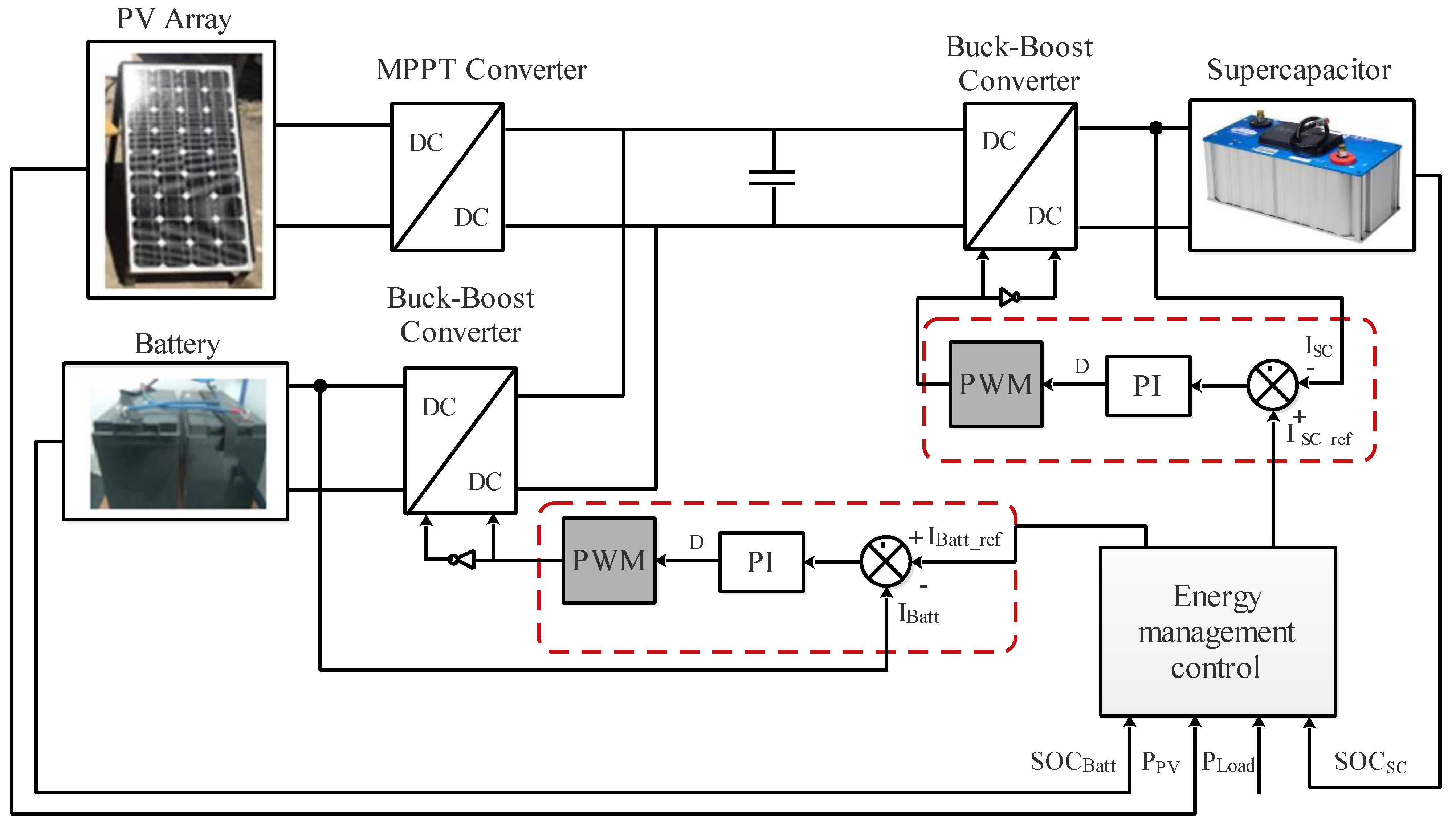
In this regard, this research aims to increase the performance of a standalone photovoltaic system with multi-storage (batteries/supercapacitors). The strategy considers the SOC and charging/discharging current of the batteries and SCs for SOC balancing-based power sharing through power converters. The batteries and SCs and photovoltaic systems are linked to DC bus via DC-DC converters, which enable improving the dynamic efficiencies of the system through the regulation of batteries and SCs charging/discharging as a function of the EMS provided when the system is exposed to variable perturbations. The contribution of this paper consists of providing simple implementations of power flow management regarding optimal energy flow between PV system, batteries and SCs system, and load. Balancing between minimal energy flows through the connecting line with minimal requirements of batteries and SCs capacity is kept. The real-time simulation/experimentation that uses MATLAB/Simulink and RT-LAB is realized to confirm the effectiveness of the designed EMS and control strategy by comparing the findings with those of other authors. The rest of this article is organized as follows: The proposed PV hybrid storage systems are defined in
Section 3.
Section 4 presents parameters identification and modelling of the different subcomponents.
Section 5 is devoted to the proposed power management control. The studied system is simulated under MATLAB/Simulink to verify the suggested control and energy management technique. The findings are presented in
Section 6. On a real-time simulator (RT-LAB), a number of experimental tests were carried out to assess the suggested control algorithms.
Section 7 describes the step description, and the results are compared to the simulation results to demonstrate the usefulness of the proposed system. Finally,
Section 8 provides the conclusion summarizing this article’s contributions.
5. Proposed Power Management Control
The buck–boost converters regulate the power flow to ensure the system runs smoothly and effectively. These are the load power requirements:
where ∆P is the power demand variation.
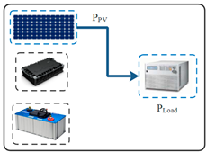
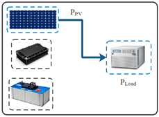
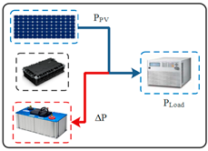
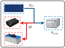
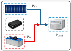
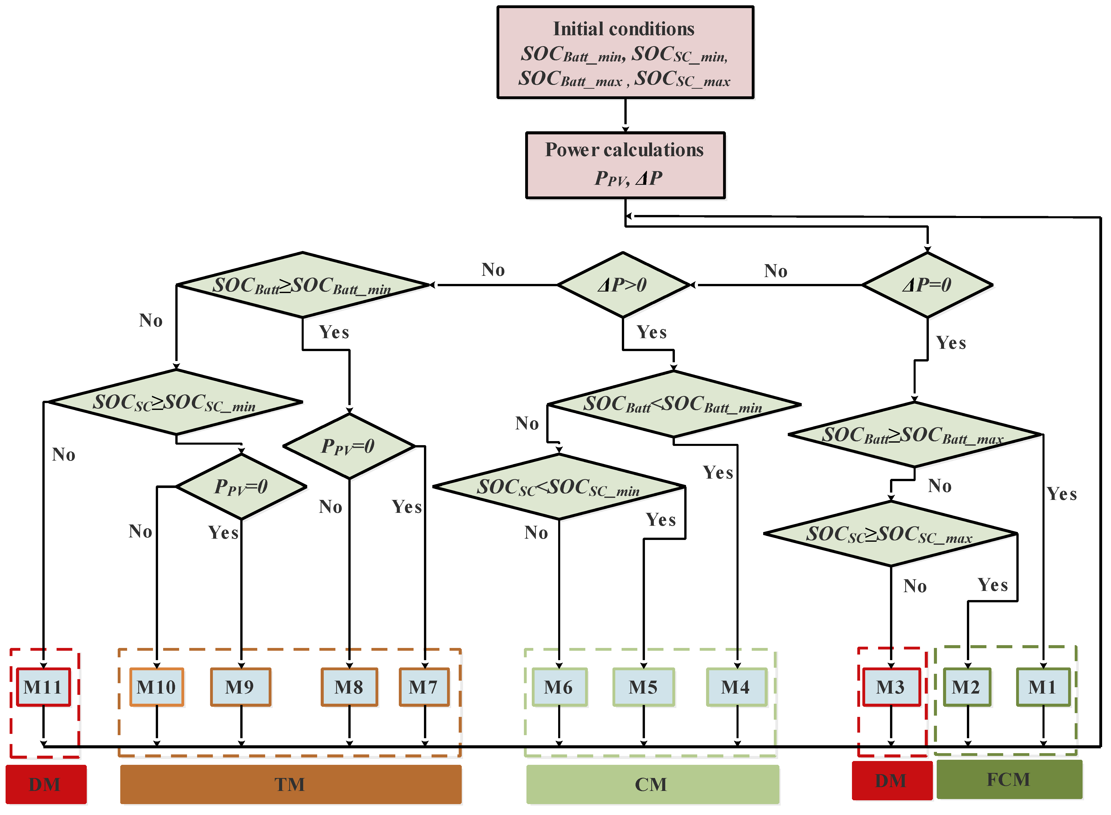
The system operates as follows: Depending on the state of the power availability requirement between the PV and load, the two storage batteries and SCs can normally operate in either charge or discharge mode. Prolonged power unbalance in the PV-storage system can result in storage deep discharge or overcharging. The PV with batteries/SCs system has three working modes: fully charged mode, normal-charging/discharging of batteries and SCs (normal mode), and transient mode (transient mode).
In this scenario, only two modes appear:M1 and M2.
M1: We disconnected the batteries because they are fully charged.
M2: We disconnected the supercapacitors because they are fully charged.
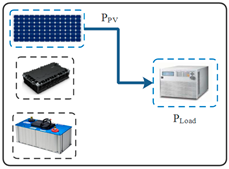
In this scenario, there are two cases. The first one is the charge mode three modes where appear—M4, M5, and M6—where extra power is sent to charge the batteries and SCs. The second case is a discharge mode with only two modes—M3 and M11—where the batteries and supercapacitors are disconnected to protect them as the load is powered by PV power.
M4: The generated photovoltaic power supply the load. Excess power is sent to charge the batteries.
M5: The generated photovoltaic electricity will be used to supply the load. Excess power is used to charge the SCs.
M6: PV supplies the load, and any excess power is sent to charge the batteries and supercapacitors.
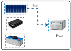
M3: When the batteries and supercapacitors are not fully charged, the algorithm acts to prevent the batteries and SCs deep discharging, so disconnecting them is the priority.
M11: The load could not be supplied by the PV, which can be very low, and we disconnected the batteries and SCs because of their low levels of SOC.
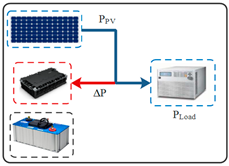
3-Transient mode (TM): We have four modes: M7, M8, M9, M10, and M11.
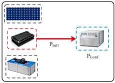
M7: The batteries are charged; the load is supplied since
and the photovoltaic power is zero.
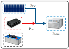
M8: As long as the batteries remain charged and the PV power is not null, they will fill up the power gap and supply the load by compensation.
M9: Since there is no PV power in this scenario, charged SCs will be used to feed the load.
M10: Since the
, SCs can provide energy, compensating the deficit of photovoltaic power.
When the batteries and supercapacitors are completely charged/discharged, the charging/discharging stops. The eleven possible modes are shown in
Table 7. The flowchart (
Figure 10) shows how it works.
6. Simulation Results
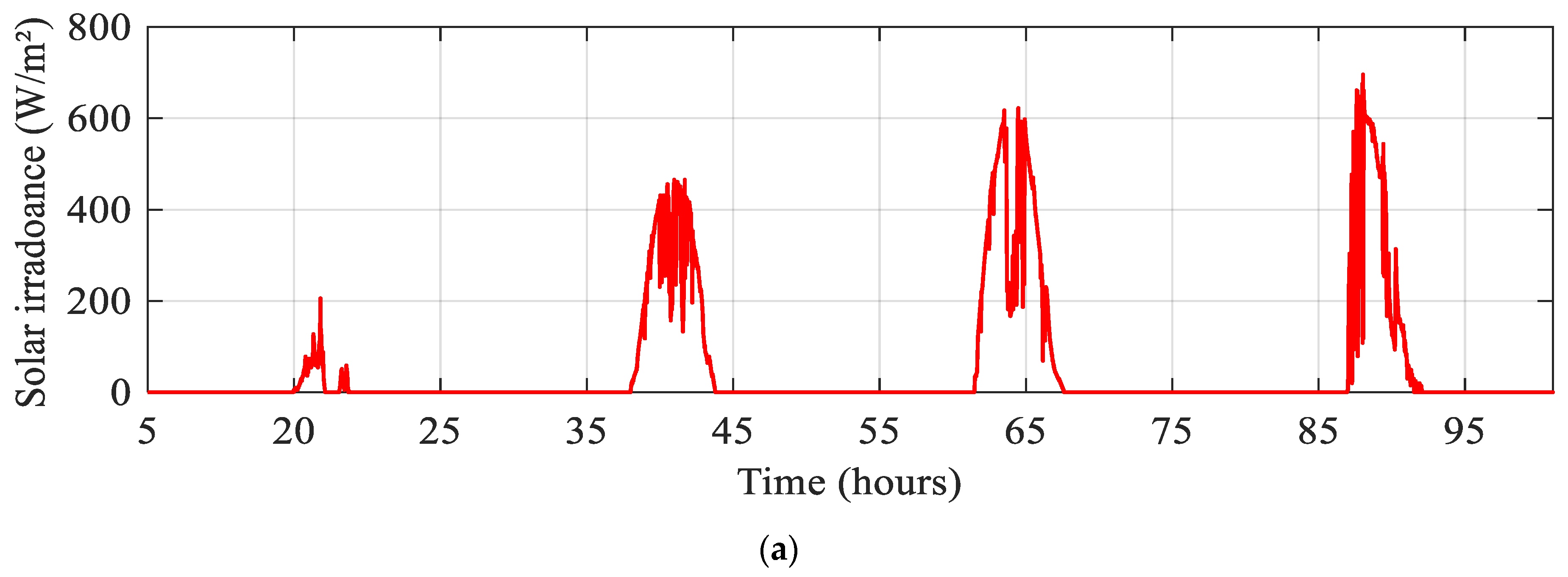
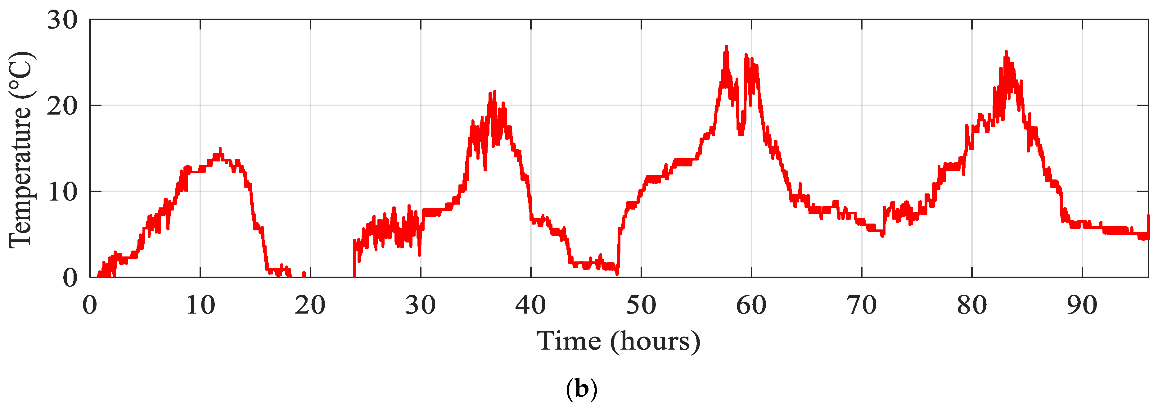
The studied system is simulated under MATLAB/Simulink to verify the suggested control and energy management technique. The simulation’s findings have been presented and analyzed. The measured profiles of solar irradiation and ambient temperature are given in
Figure 11a,b, respectively.
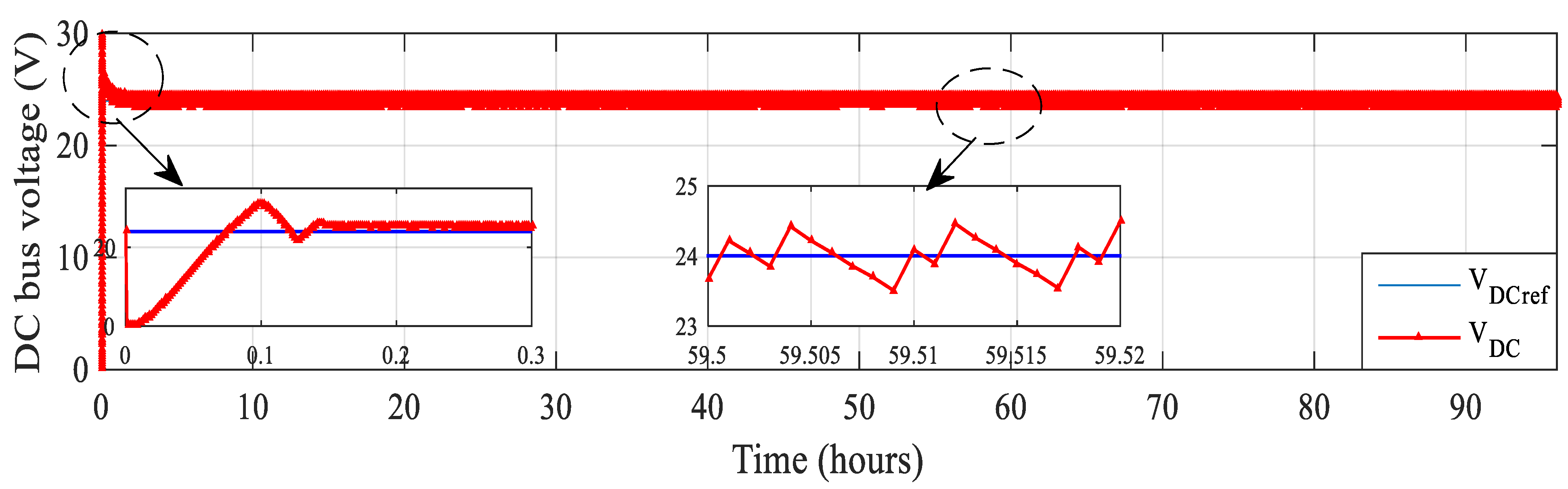
DC bus voltage closely tracks its reference (
Figure 12). It is regulated in the desired voltage and remains at its reference (V
DCref = 24 V), with low fluctuations (ΔV = 0.98% < 1%). Finally, the voltage V
DCref meets the load demands with great control efficiency. A well-performing V
DCref permits proper operation in the studied system. This result indicates the effectiveness of DC bus voltage regulation that contributes to the optimal operation.
Figure 13 presents the simulated voltage profiles of the battery and supercapacitor over time. The batteries and SCs voltage vary in accordance with the power absorbed/injected into the DC bus. Monitoring these voltage profiles is crucial to ensure that the energy storage components are appropriately charged and discharged. Proper voltage control helps maximize the efficiency and lifespan of the energy storage system. By presenting these simulation results and profiles, the study demonstrates the practical application of the proposed control and energy management technique. Analyzing these outcomes allows researchers to evaluate how well the suggested approach performs under varying environmental conditions and dynamic system behavior. It also provides insights into the system’s response to different inputs and perturbations, helping validate the efficacy of the strategy.
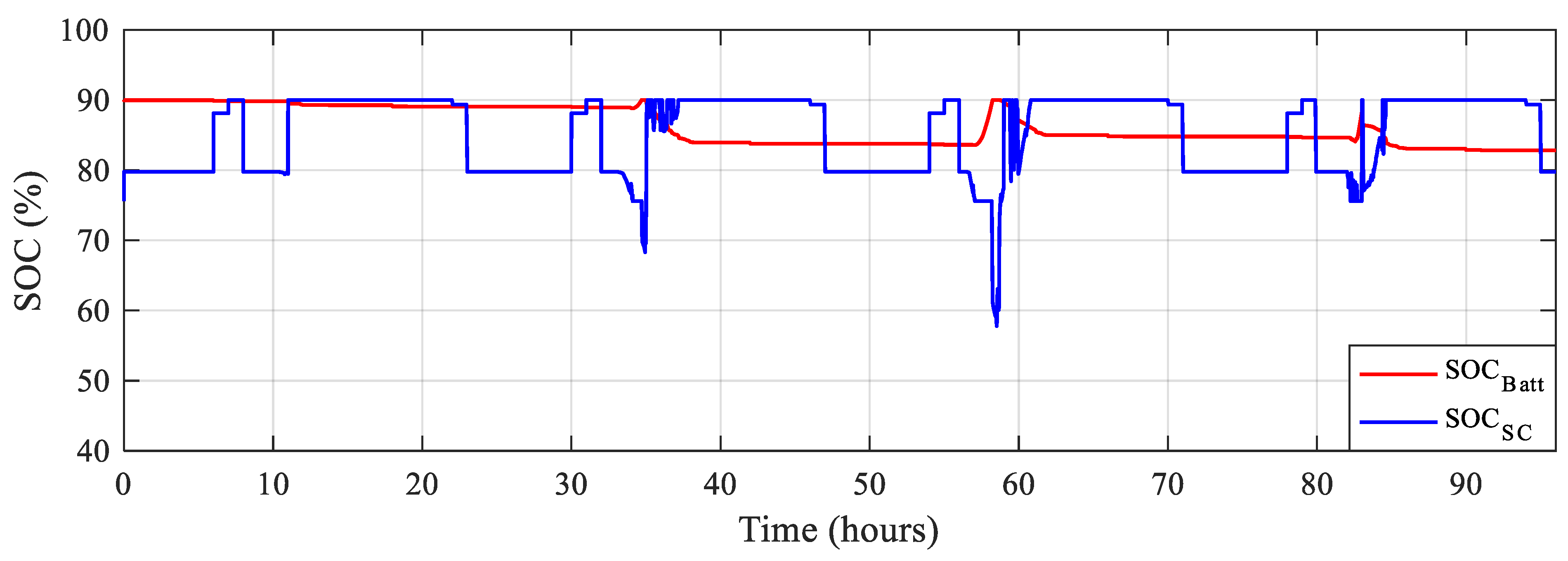
It is noticed in
Figure 14 that the battery SOC is well controlled and is maintained between 82.85%and 90% while supercapacitor SOC varies between 58.05% and 90%. The batteries and SCs SOCs are kept within bounds, regardless of the variations in PV and load power profiles.
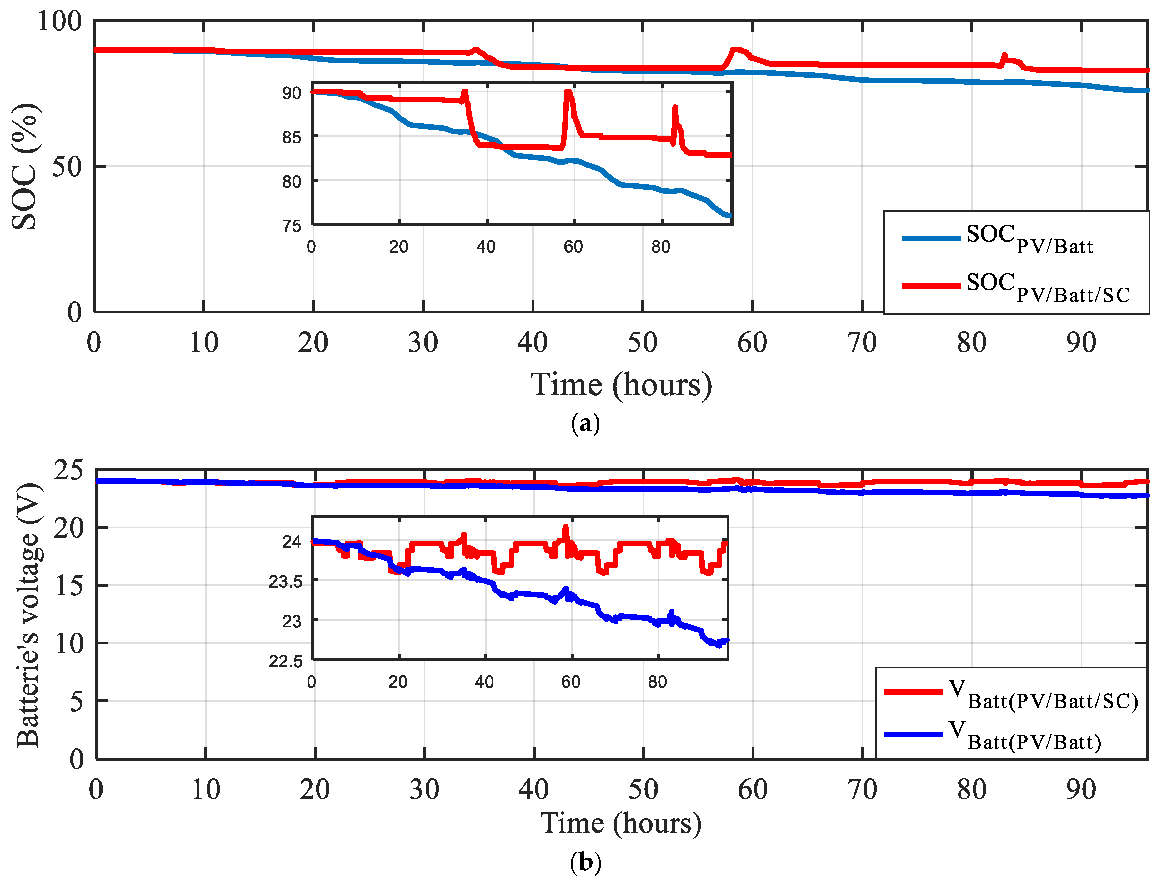
We have conducted a simulation comparing two scenarios: one with only battery storage and another with a hybrid storage system by incorporating both batteries and SCs. Based on our simulation results (specifically shown in
Figure 15a,b), we have observed that introducing supercapacitors in the storage system led to a reduction in stress on the batteries. In the scenario with only battery storage, the SOC started at 75% and decreased over time. However, when supercapacitors and a well-implemented control loop were introduced in the system, the battery SOC remained relatively constant and reached a minimum value of 82.85%. It suggests that adding supercapacitors helped regulate the battery SOC and prevent it from dropping significantly. In the battery-only scenario, the battery voltage likely fluctuated as the SOC decreased, which is typical behavior for batteries. The battery voltage remained relatively stable with some fluctuations with the hybrid storage setup including supercapacitors and a control loop. This stability indicates that the supercapacitors might be assisting in maintaining a steady voltage level, contributing to more consistent system performance.
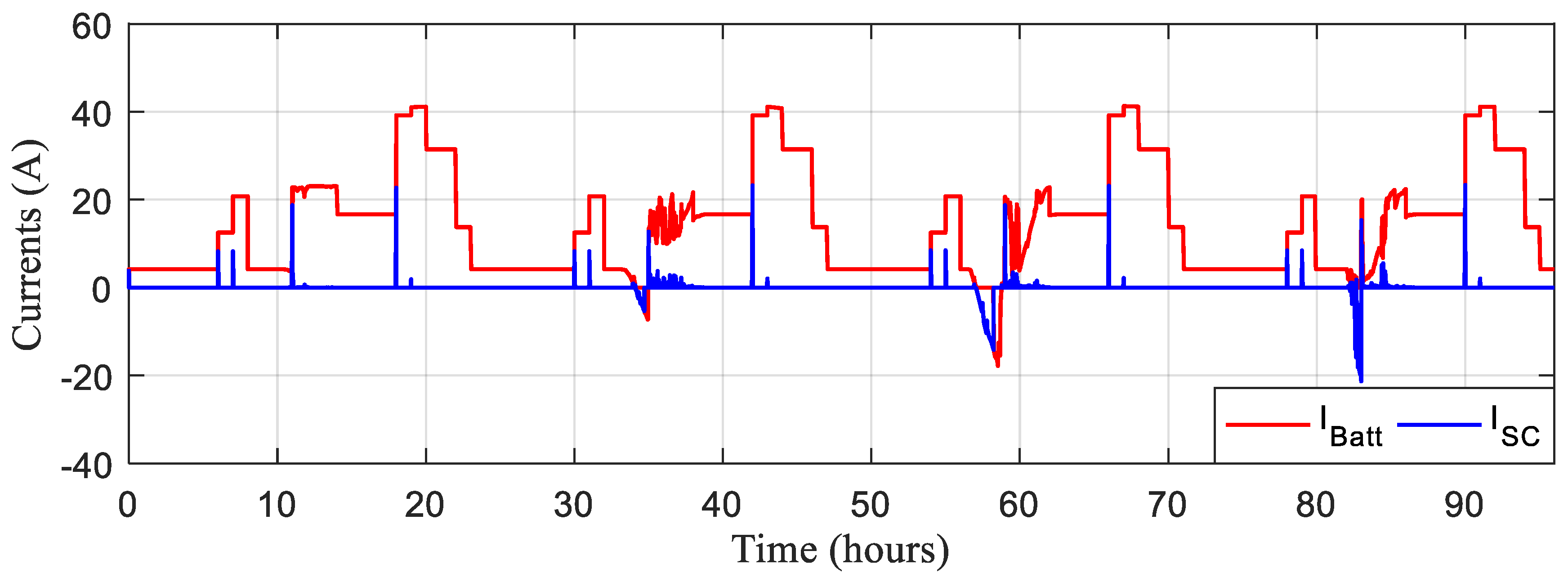
Figure 16 shown below points out the battery and supercapacitor currents.
The different resulting modes are given in
Figure 17. During each cycle, batteries and SCs are discharged and then rapidly recharged at M4 and M6 modes (for batteries and at M5 and M6 for SCs). The only cases of disconnection are during M3 where ΔP = 0 but the load is powered entirely by photovoltaics, and during M11 where the load is disconnected.
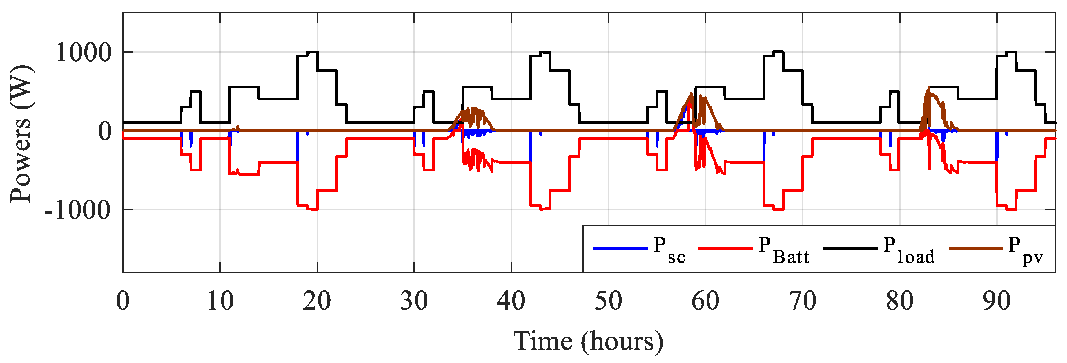
Figure 18 depicts the battery, supercapacitor, and PV powers all at once.
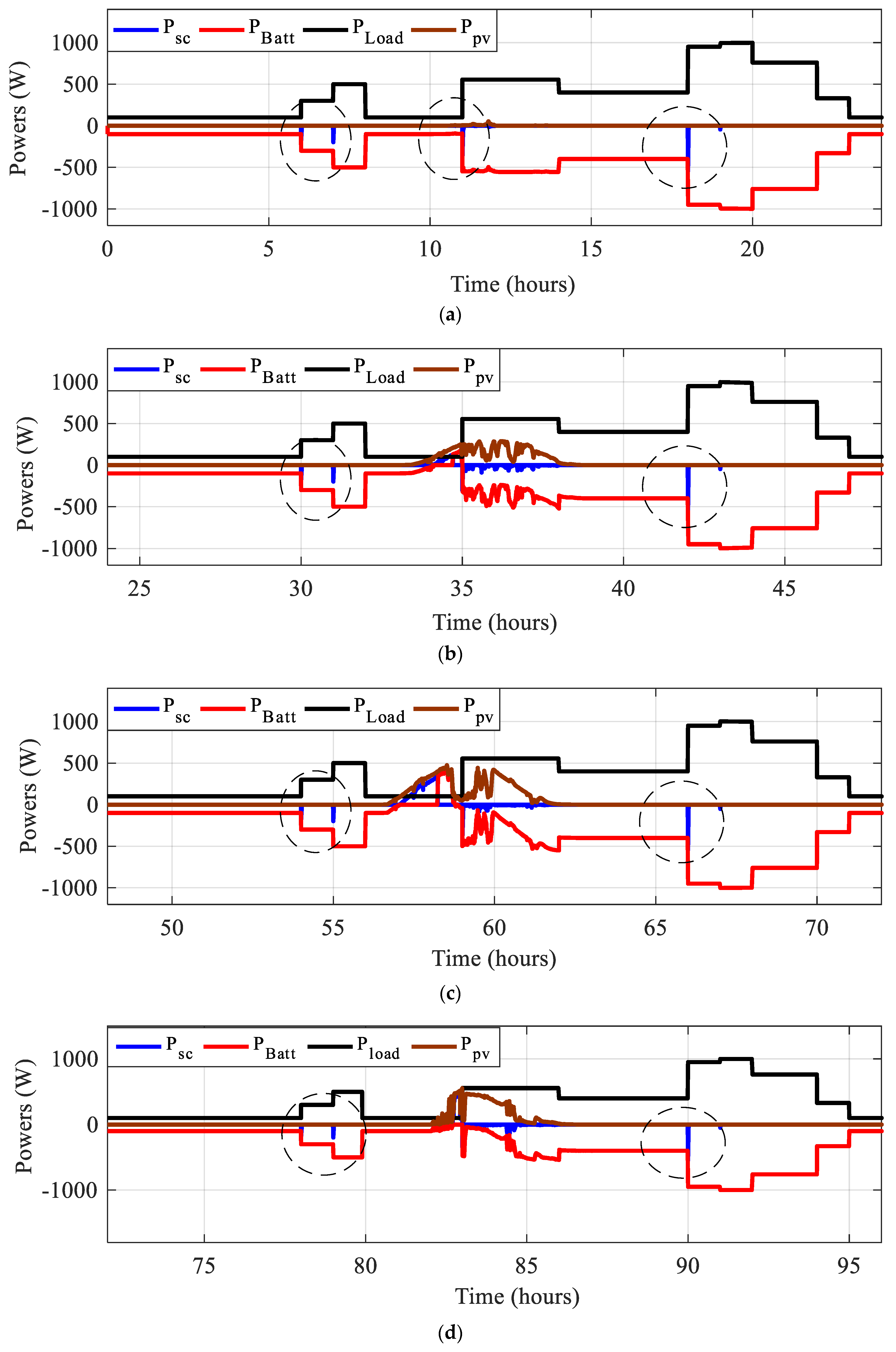
Figure 19 depicts the power per day of all power sources for four distinct days. The PV power varies with the profile of solar irradiation. Despite changes in load requirements, the curve of maximum available PV power aligns with solar irradiance variation, validating the suggested MPPT. To better depict discharges in relation to PV and load changes, battery and SC powers are presented in negative. It should be noted that the negative sign of the batteries’ and SCs’ powers indicates that they are recovering power, while the positive sign indicates that they are supplying the load. They alter its charging course (sign).
During the first day (
Figure 19a), where solar irradiance is very low and does not exceed 200 W/m
2, the battery is highly stressed and is supported by the SC during sudden changes in load (at t = 6, 7, 11, and 18 h). The most frequent modes are M7, M8, M9, and M10, as ΔP is always negative. On the second day (
Figure 19b), when maximum solar irradiation is around 460 W/m
2, the same observations were made, with slightly less stress on the batteries, assisted by the SC, at times of abrupt load changes (t = 31 and 41 h). On the third day (
Figure 19c), solar irradiance reached 620 W/m
2, and up to 740 W/m
2 on the fourth day. On these last two days, we note less stress on the batteries and the presence of modes M4 and M5, corresponding to battery and SC charging.
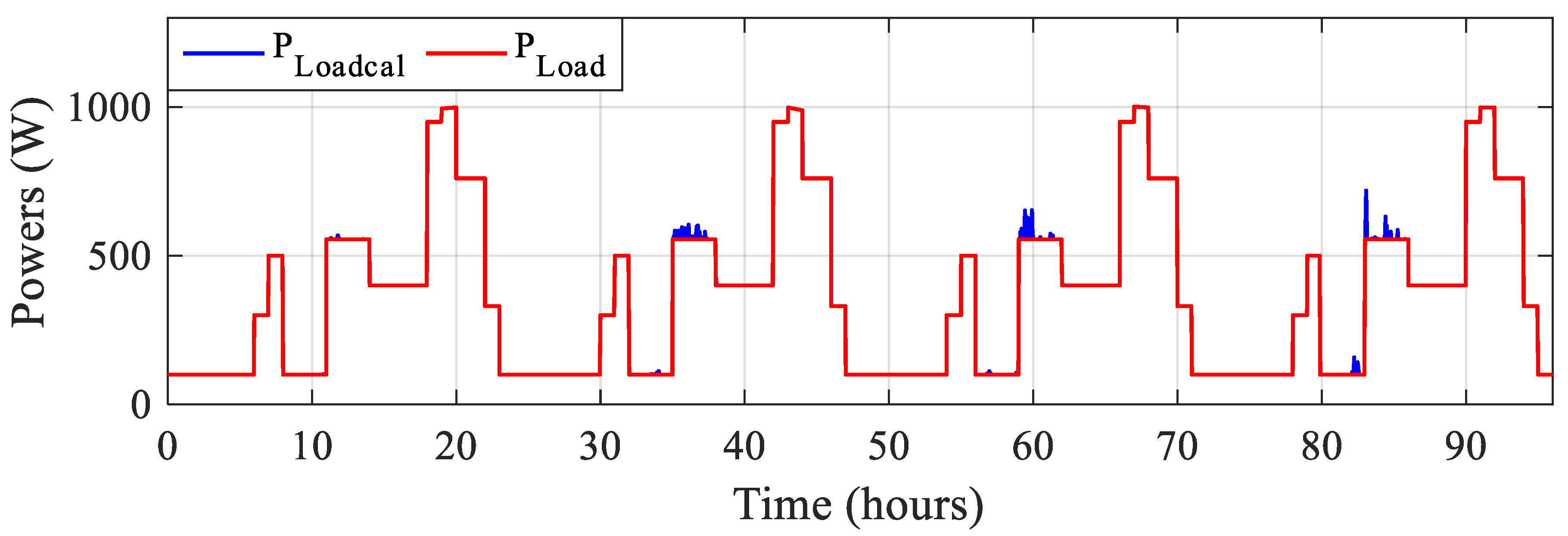
The reference load power and the sum of power developed by all the power sources are shown in
Figure 20, respectively.
The zoom of this last-mentioned figure for four distinct days is shown in
Figure 21.
Sometimes the calculated power is more than the developed load power. The power surplus has been computed (
Figure 21). Despite adequate size and the use of PMC, it is noted that a slight surplus of power is obtained, which can reach a maximum of 100 W on the last day of strong sun irradiation. They demonstrate the suggested control and energy management technique’s performance with regard to state of charge, current profiles, operating modes, power output and consumption, and load needs alignment. These visual representations provide insights into the system’s behavior under various settings and indicate the research approach’s feasibility and practicality.
7. Real-Time Simulation
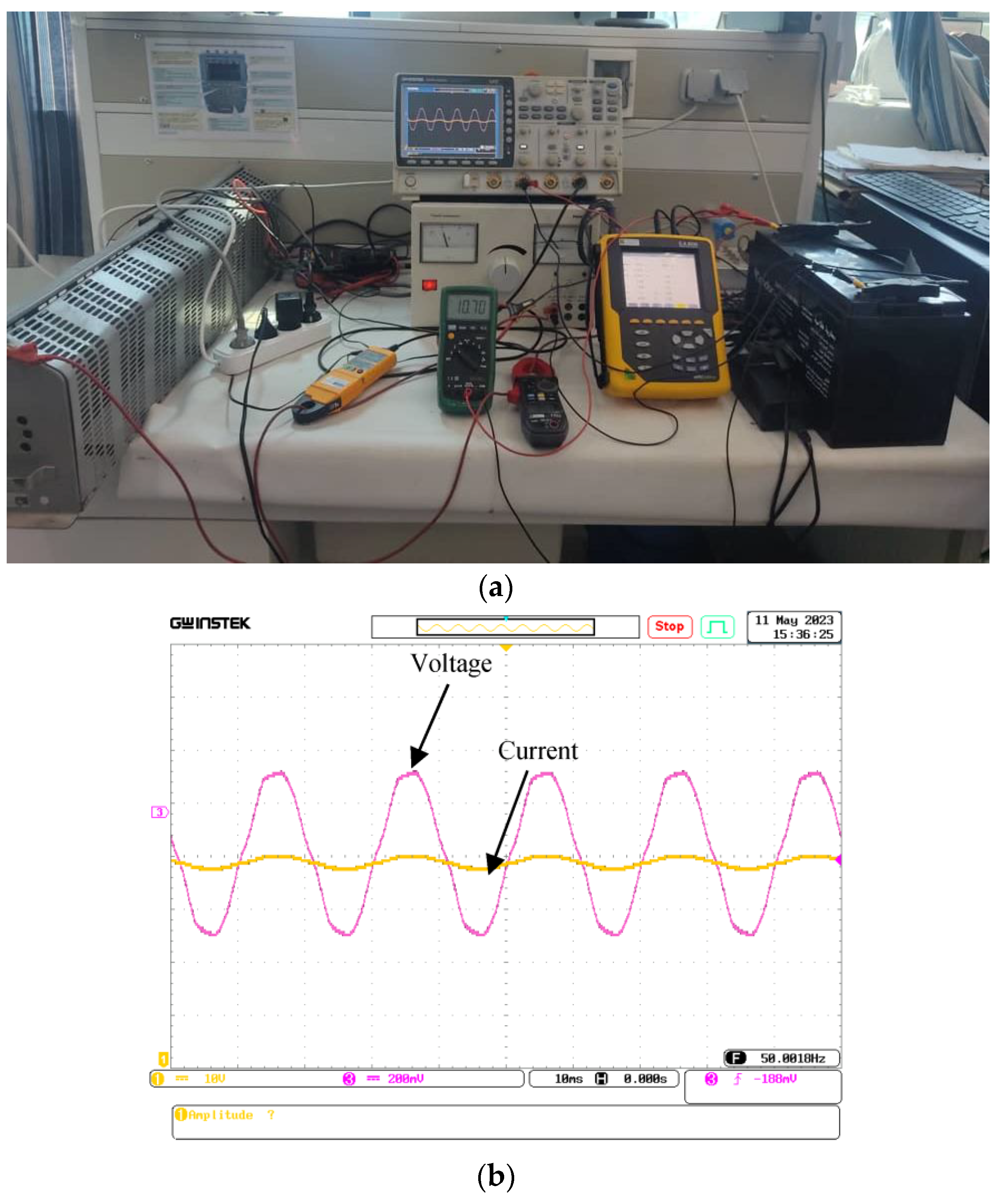
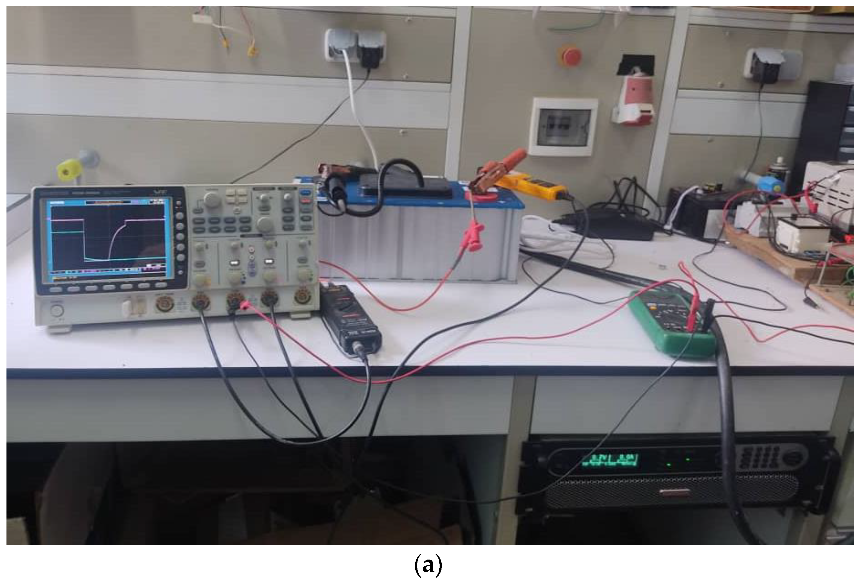
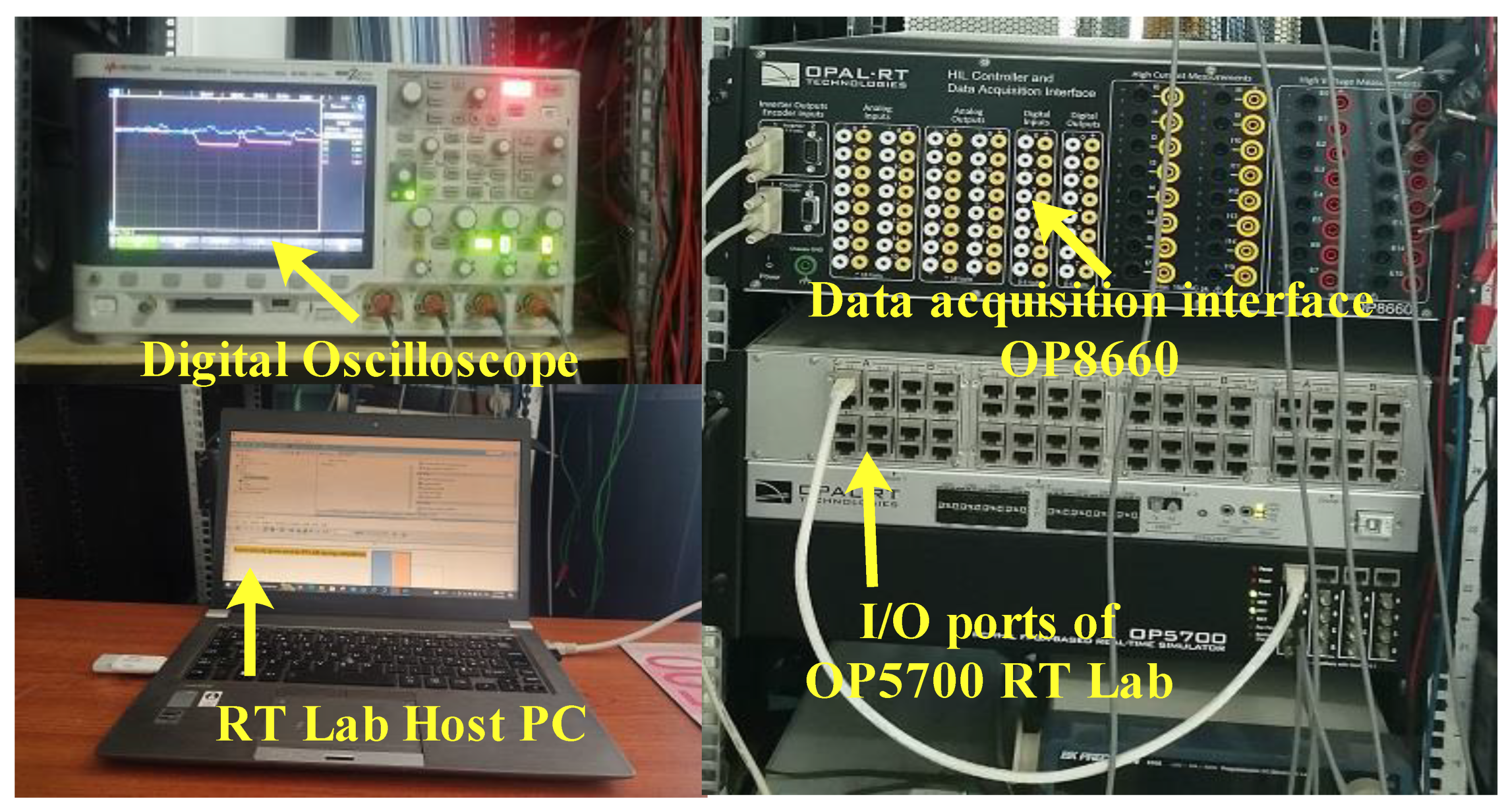
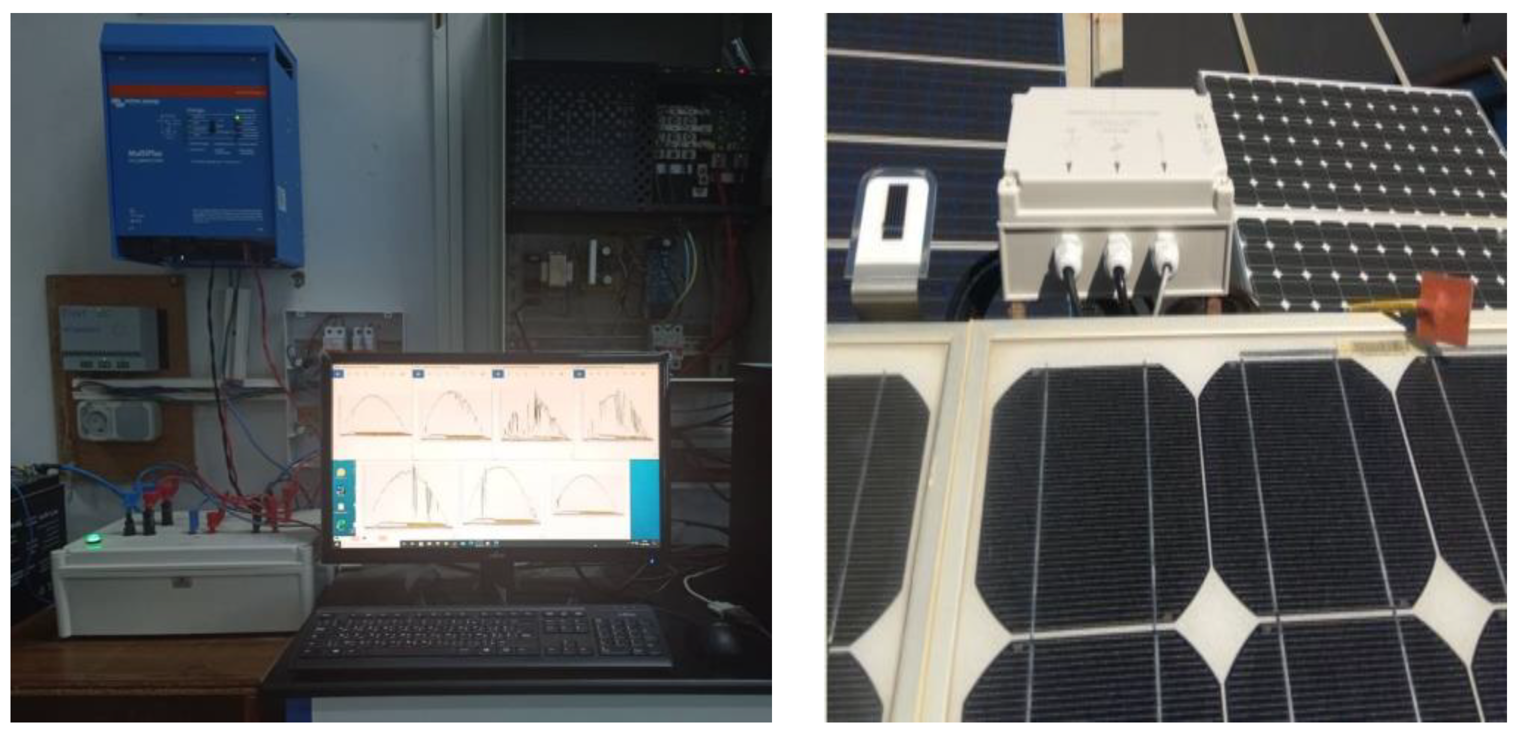
A series of experimental tests were performed on a real-time simulator (RT-LAB) to evaluate the proposed control methods. The system settings remained unchanged from the MATLAB/Simulink numerical simulation. The real-time simulation bench (
Figure 22) consists of a host PC, a real-time digital simulator (OP5700), an HIL controller, an OP8660 data collection interface, and a digital oscilloscope. Maintaining system parameter consistency, employing particular hardware components, and displaying the experimental bench using a given diagram (
Figure 22) were all part of the setup. These real-time experiments validate the proposed control strategies in a practical environment, adding a layer of real-world verification to the findings of the simulation-based study.
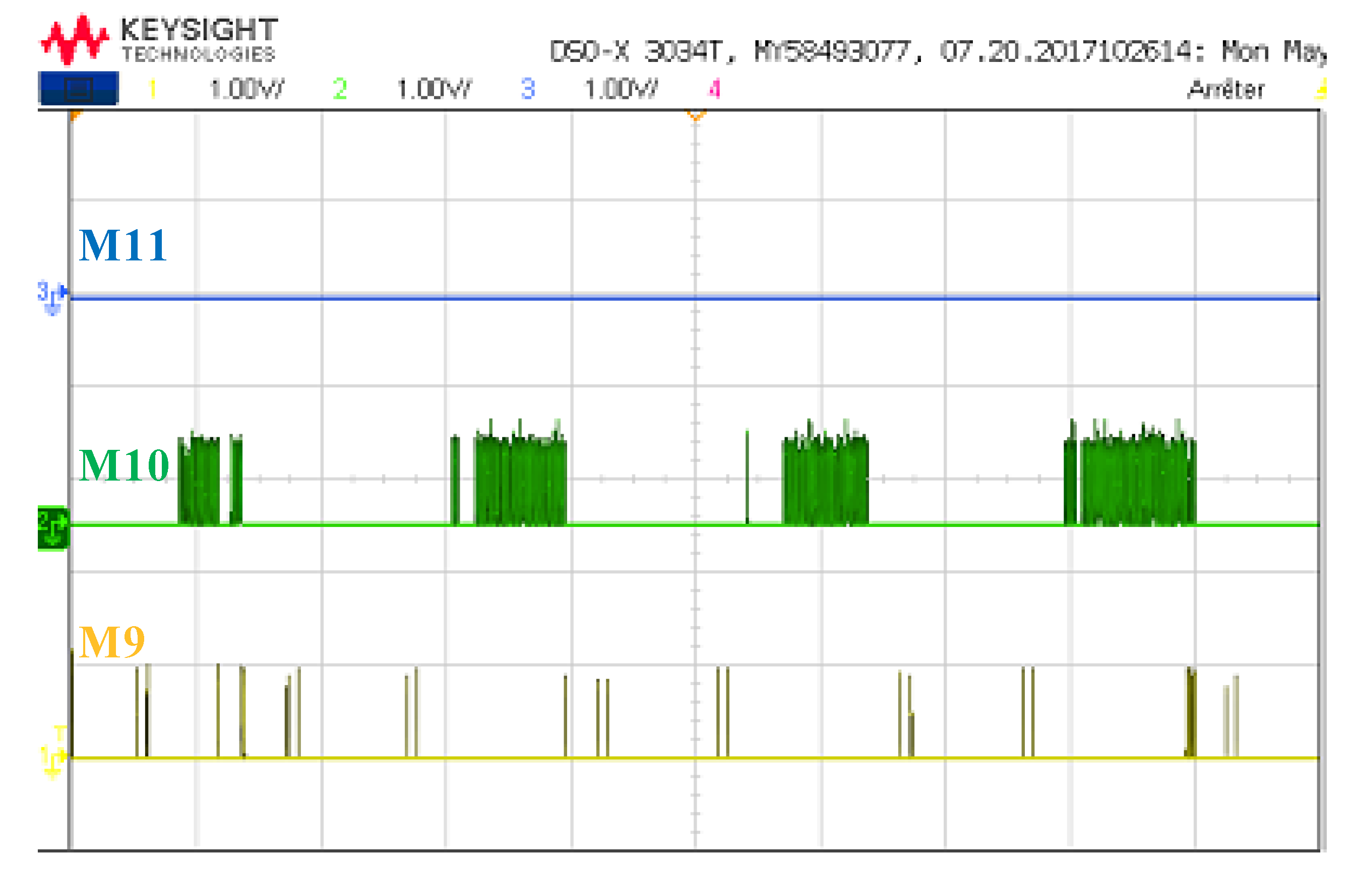
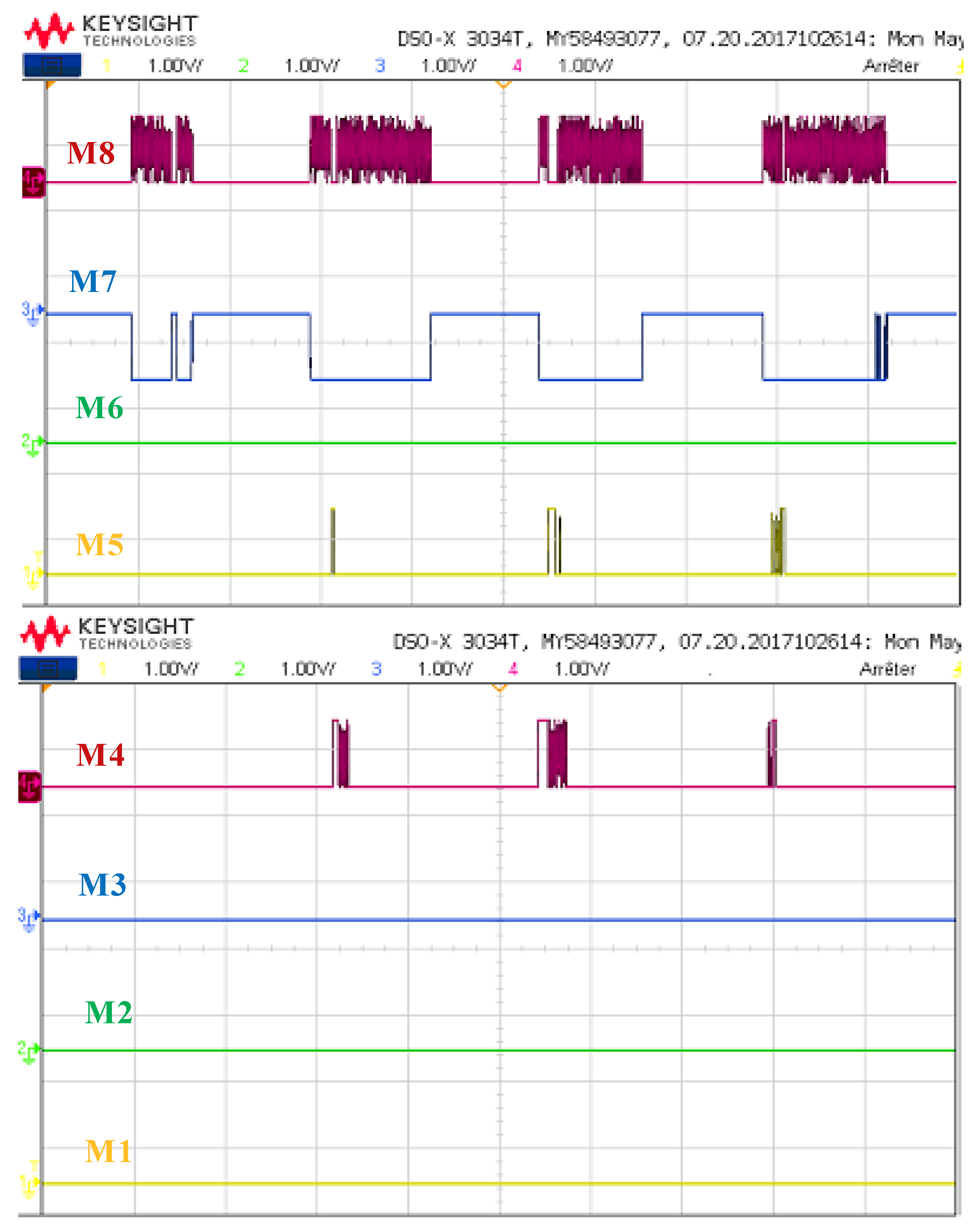
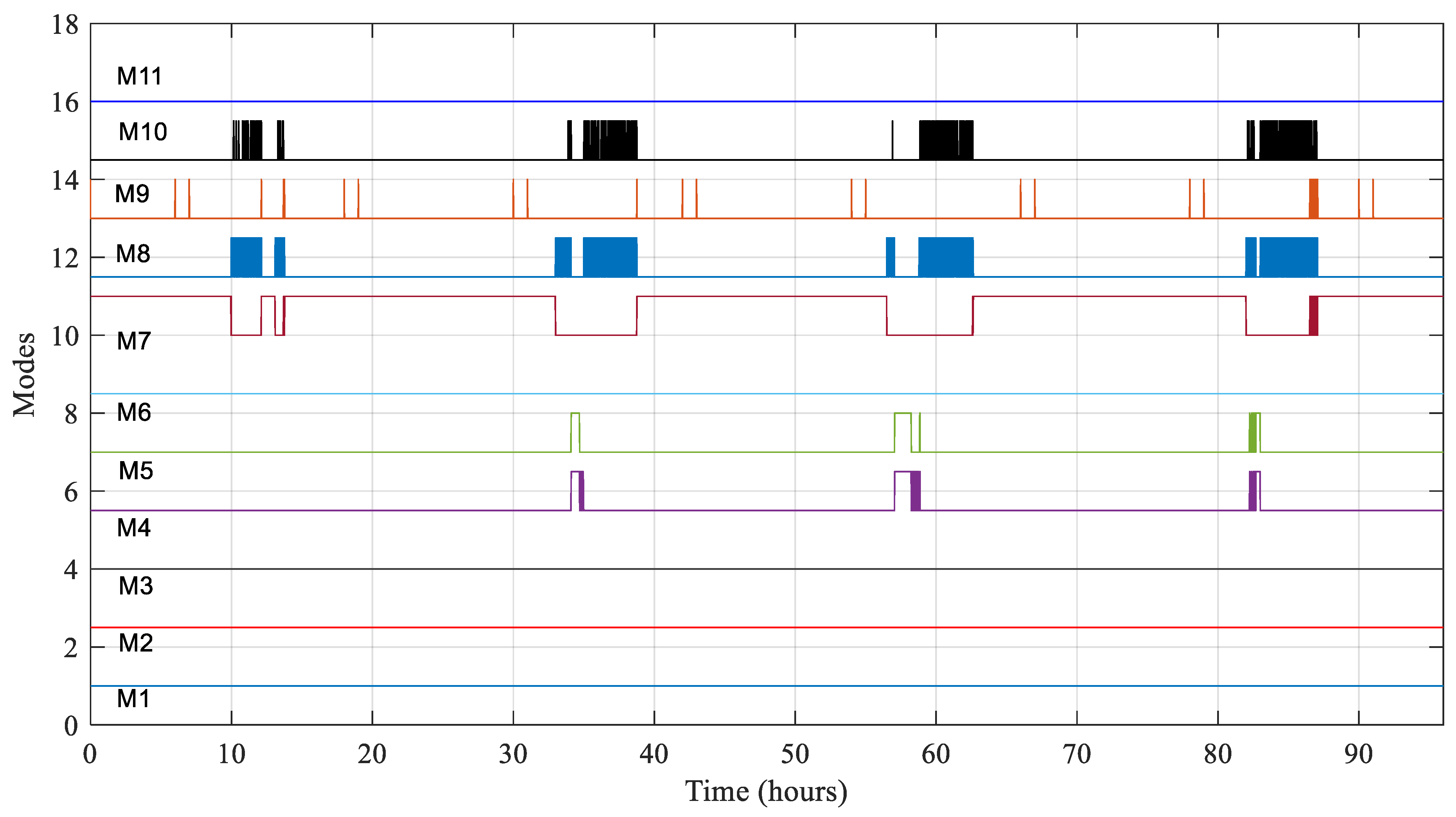
Figure 23 shows the different obtained modes when the energy management strategy is run using the RT-LAB real-time simulation platform. The scheduled modes from 1 to 11 are highlighted to demonstrate the efficacy of the suggested management.
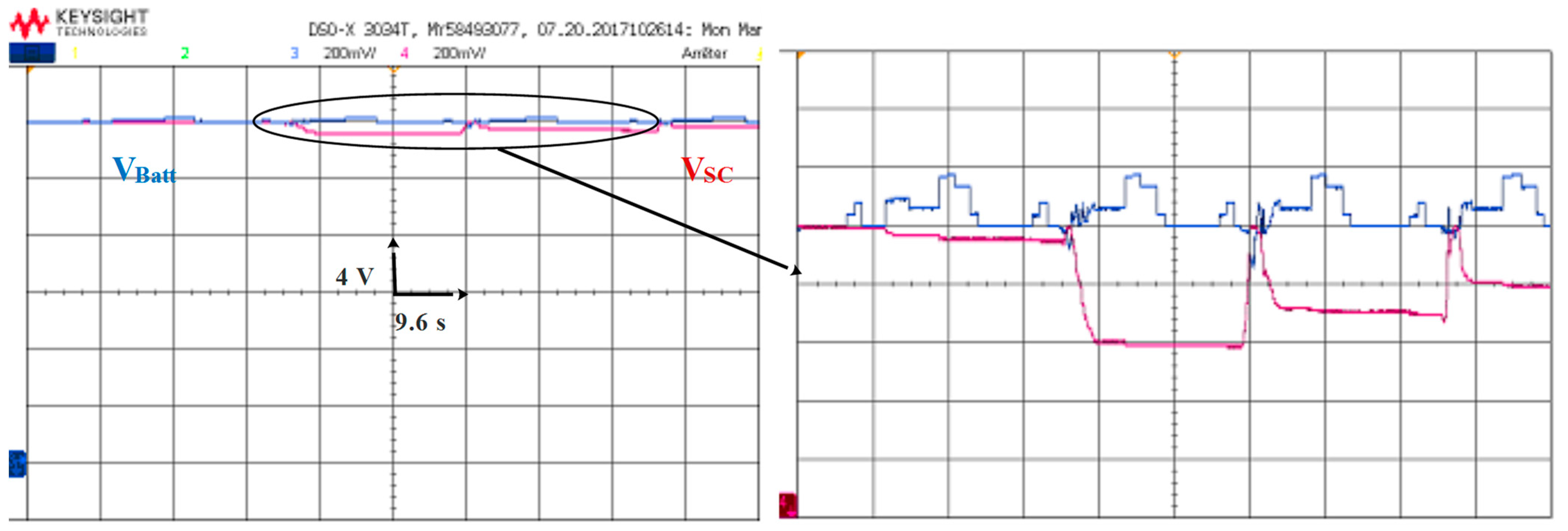
Battery and supercapacitor voltages and their corresponding zooms are highlighted in
Figure 24.
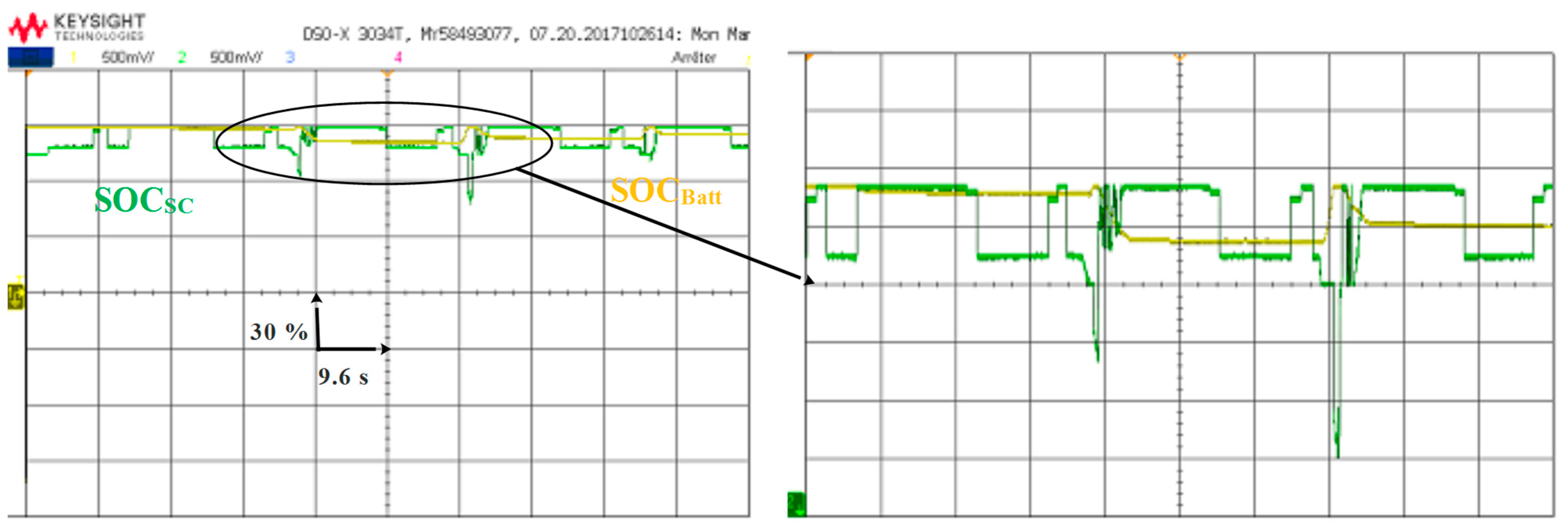
The SOC of both the supercapacitor and the battery are shown in
Figure 25. The zoom in the same figure confirms that the SOC of the previously mentioned power sources is kept within safe limits during all the simulation periods.
Figure 24 and
Figure 25, along with their corresponding zooms, provide detailed insights into the behavior of the battery and supercapacitor within the energy management system. It highlights voltage profiles, SOC behavior, and their alignment with safe operating limits, reinforcing the successful performance of the suggested energy management strategy in maintaining optimal conditions for the energy storage components.
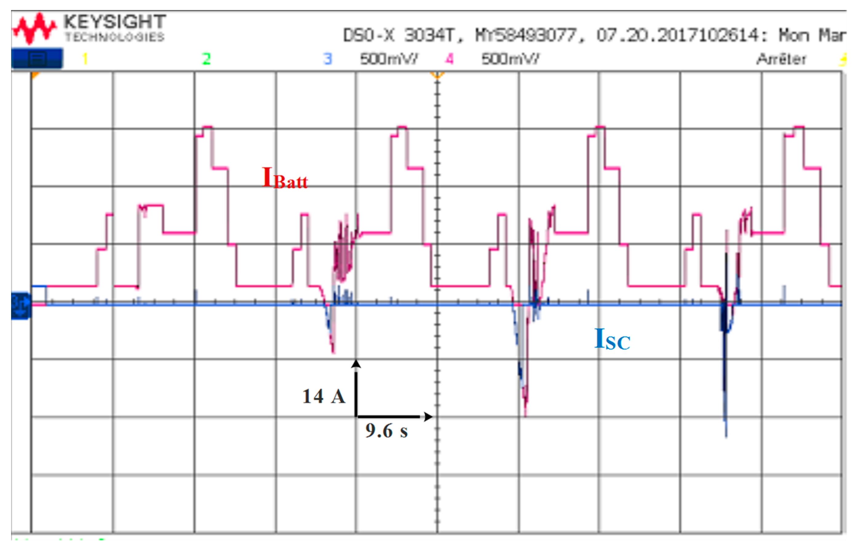
The battery and supercapacitor currents are represented in
Figure 26. It is noticed that the battery is used during low and medium power demands. However, during fast and peak load demands, the supercapacitor is used because of its rapid transient dynamics.
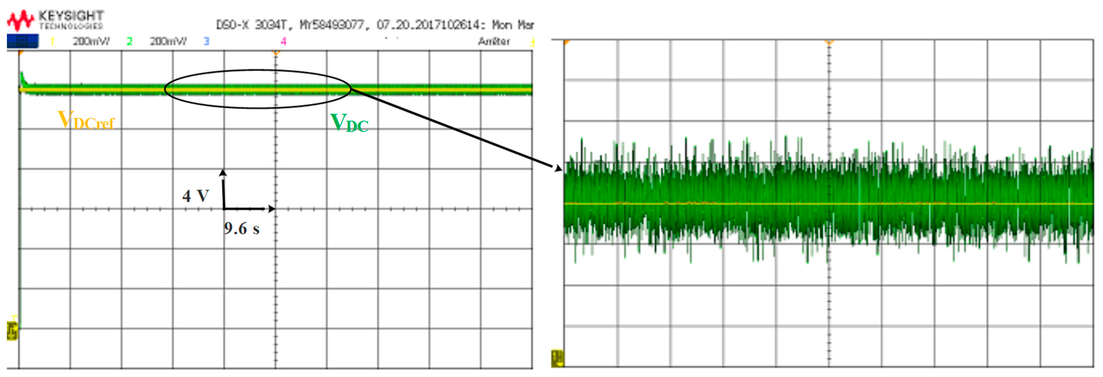
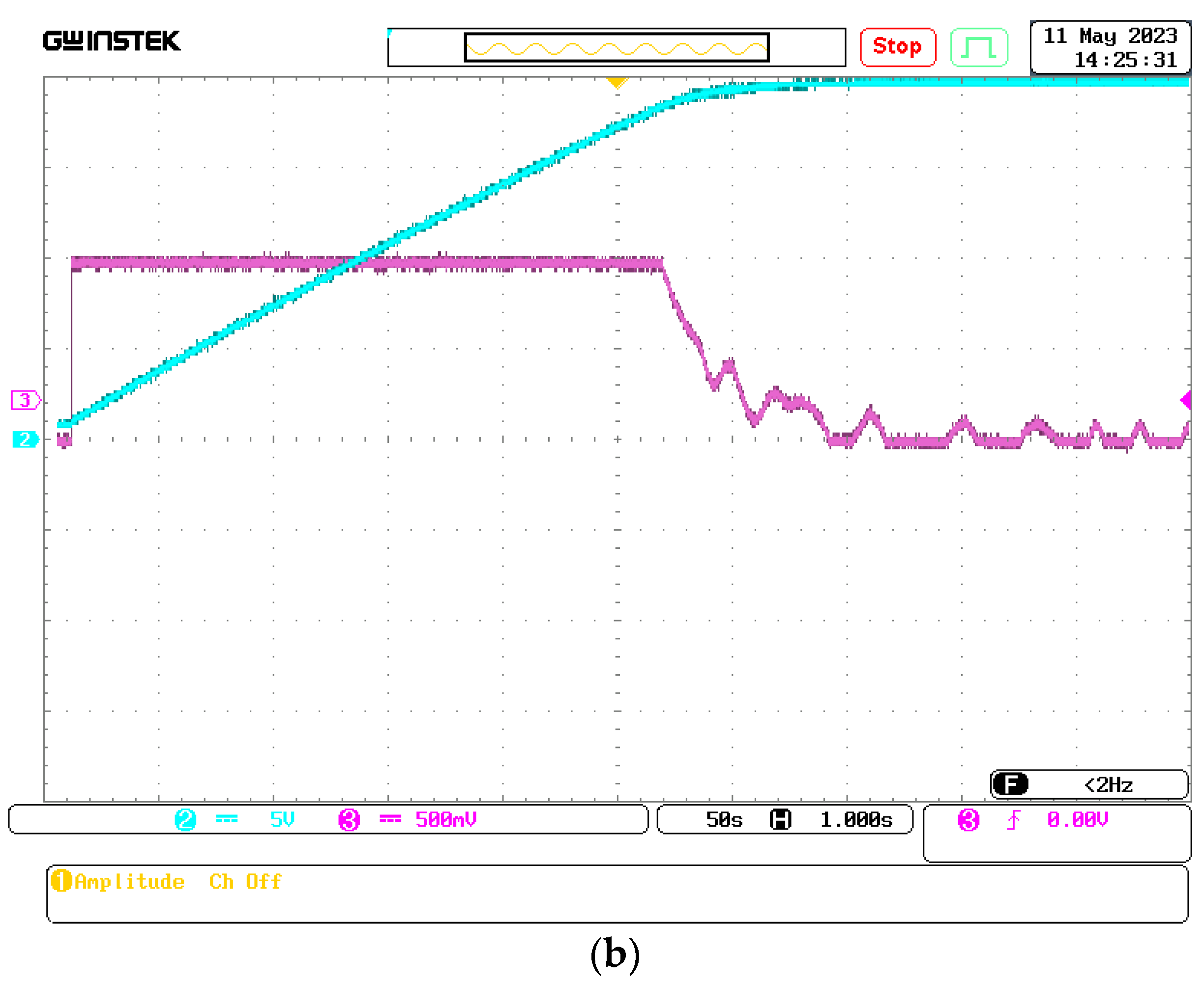
Figure 27 shows the reference DC bus voltage, its reference, and a zoom of the aforementioned quantity. It can be seen clearly that V
DC precisely follows its reference. Note also that the voltage ripple band is small and tolerable.
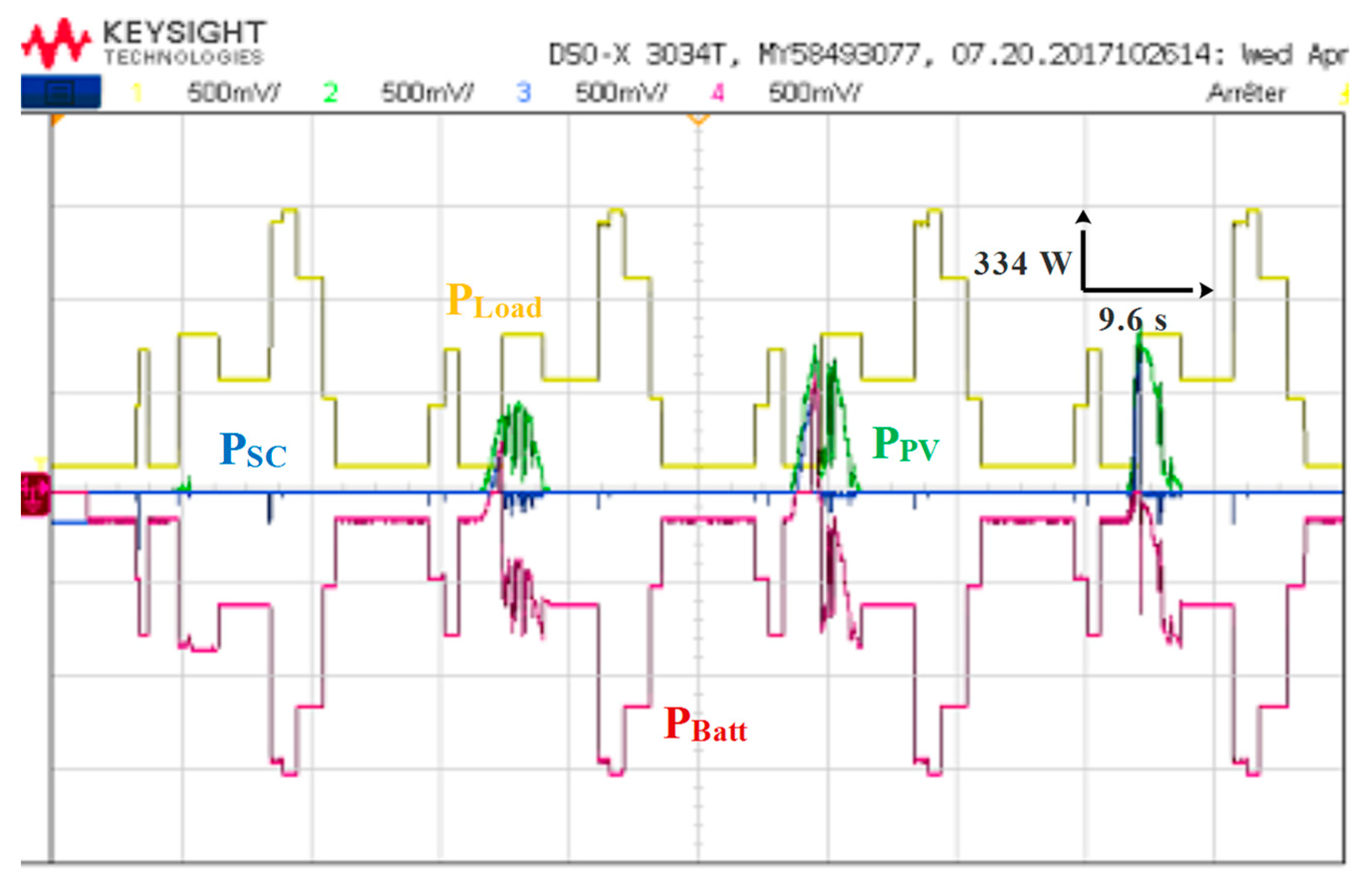
The power developed by each energy source is shown separately in
Figure 28. As shown in
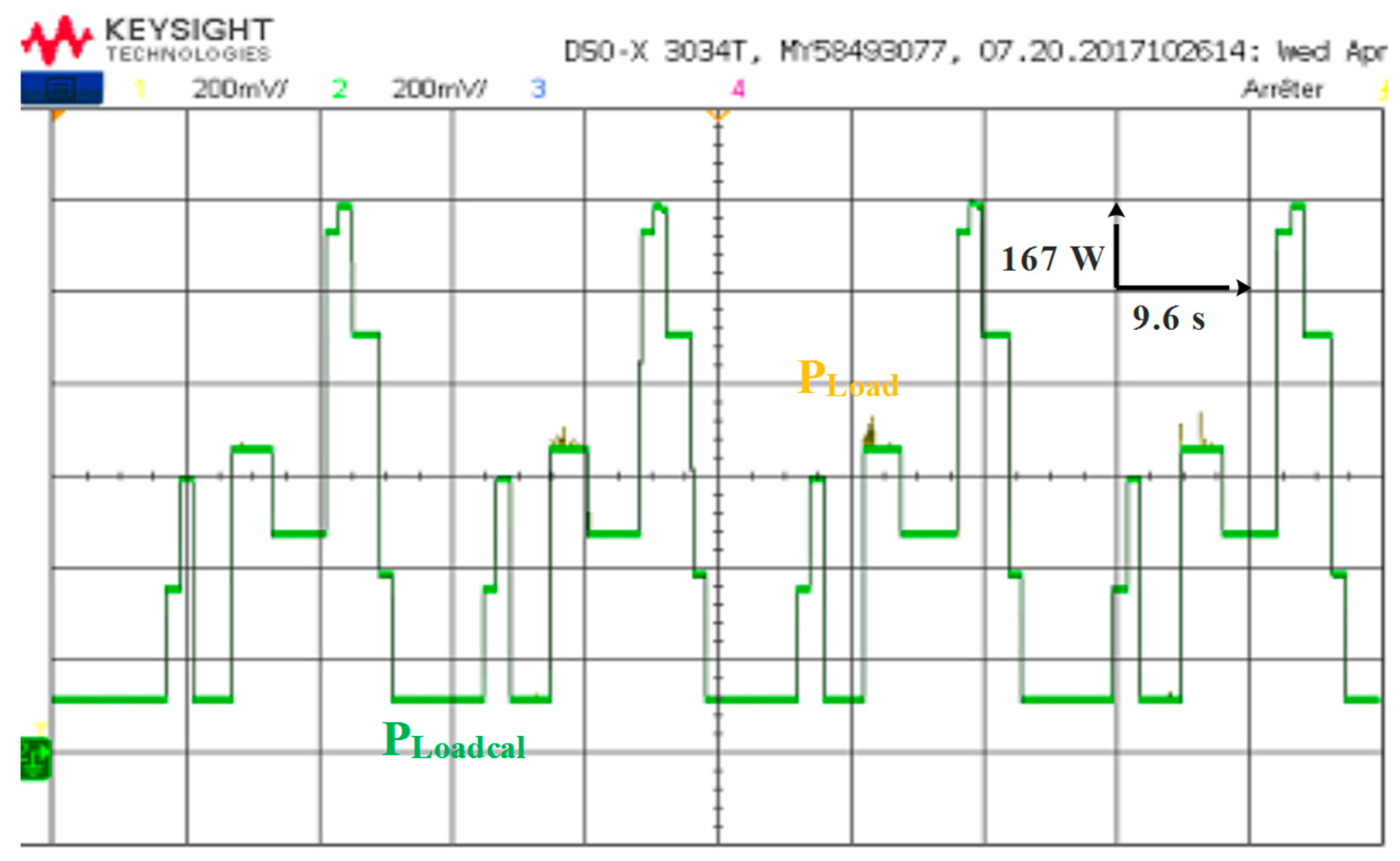
Figure 29, the load power equals the developed power.
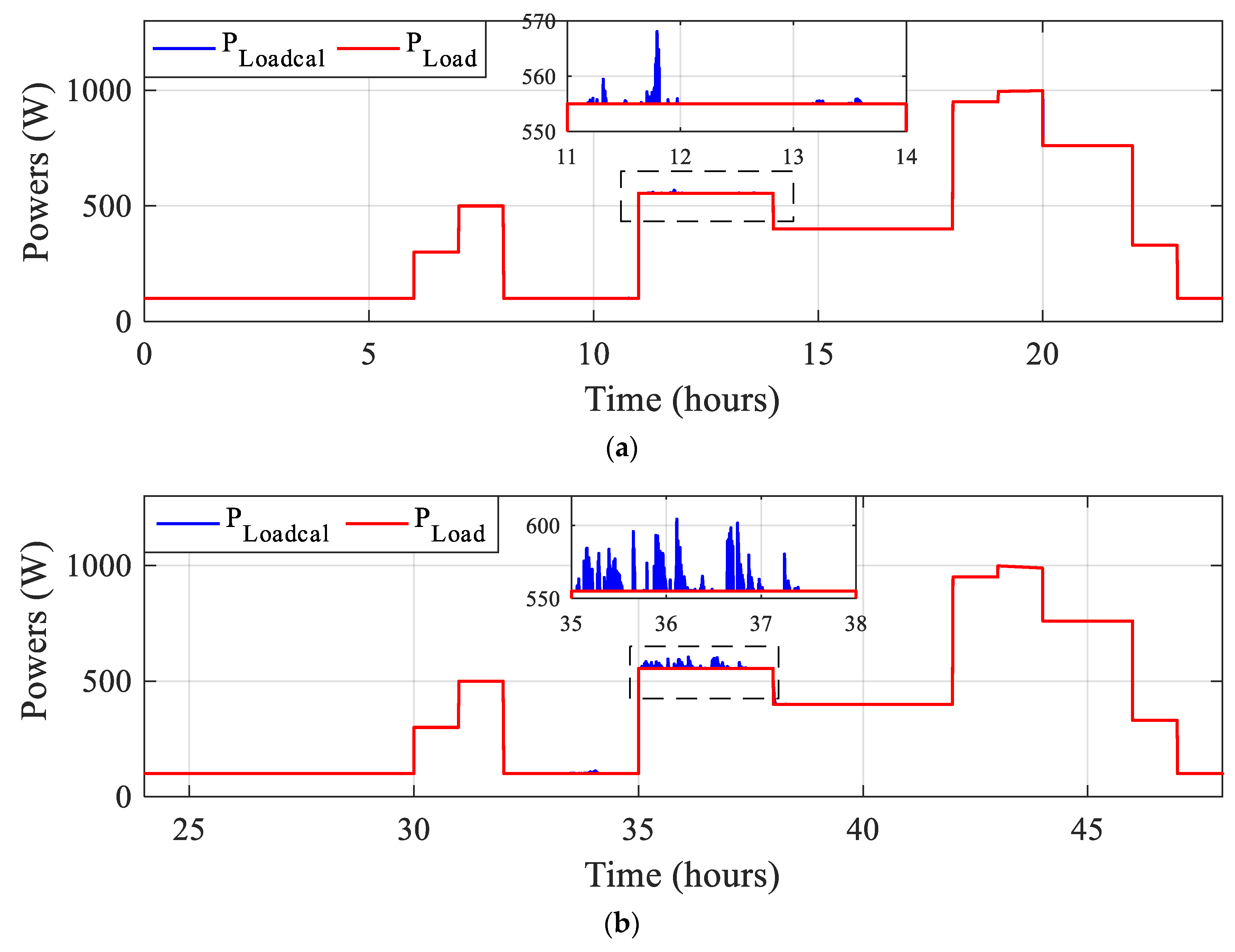
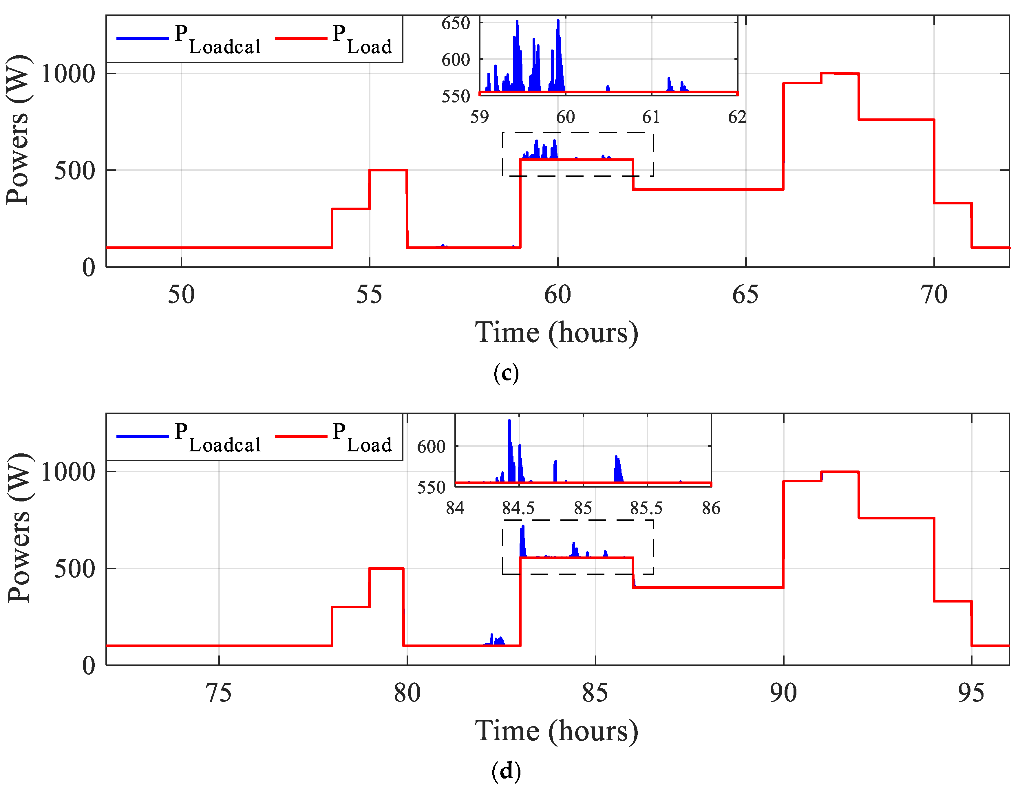
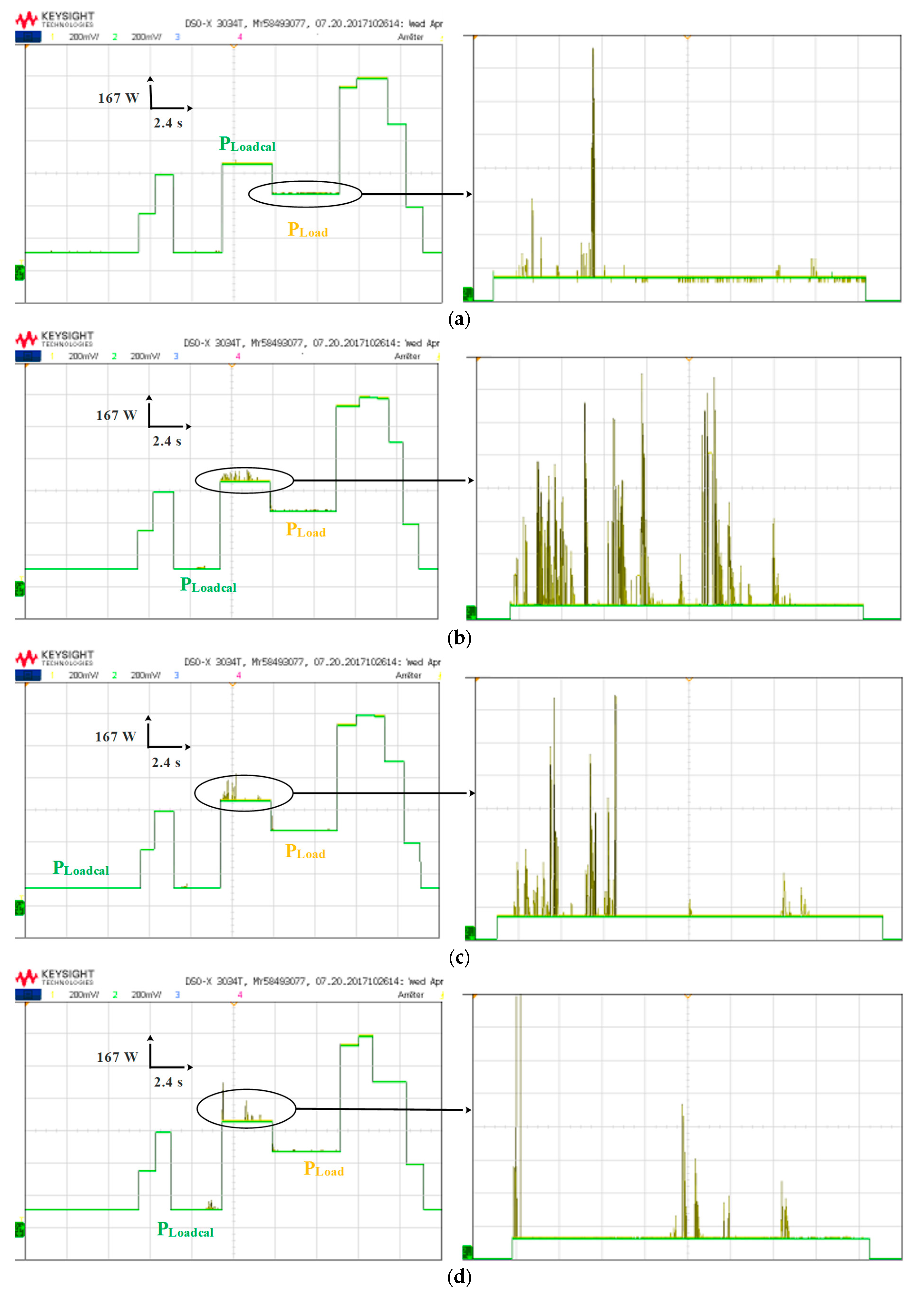
One can notice that the storage system produces a power that is equivalent to the total demand with a little excess as illustrated in the different subfigures of
Figure 30a–d illustrated below:

 ,
, 


