Article

Latent Thermal Energy Storage for Solar Industrial Drying Applications

Ecole Supérieure de Technologie de Fes, Université Sidi Mohamed Ben Abdellah, Route d’Imouzzer, Fes BP 2427, Morocco
Sustainability 2023, 15(17), 13254; https://doi.org/10.3390/su151713254
Submission received: 13 July 2023 / Revised: 22 August 2023 / Accepted: 1 September 2023 / Published: 4 September 2023
(This article belongs to the Section Energy Sustainability)

Abstract

:
Solar heat is an attractive alternative in industrial processes. However, the intermittent and stochastic nature of solar energy necessitates the use of heat storage systems to bridge the gap between heat production and demand. This study introduces a validated numerical analysis approach to investigate the performance of latent storage tanks filled with spherical phase-change materials. A 1D thermal model is developed to describe the charging processes of adipic acid as PCM. The study examines the performance characteristics of latent heat storage in terms of stored energy and duration through parametric investigations. For mass flow rates ranging from 600 to 1000 kg/h, storage durations were found to vary from 440 to 582 min. The storage duration decreased significantly from approximately 1150 min at a charging temperature of 160 °C to 470 min at a charging temperature of 240 °C. The bed porosity affected the storage process, with a porosity of 0.5 achieving a thermal energy storage of around 344 MJ but requiring a longer charging time of about 610 min. Higher heating rates allowed for lower storage durations, with storage durations of approximately 460 min for a heating rate of 3 °C/min, compared to 660 min, for a heating rate of 0.5 °C/min.

1. Introduction

The industrial sector accounted for approximately 9.4 Gt of CO2 of the global energy-related emissions in 2021, which represents 25% of total emissions, making it one of the most critical sectors from an environmental perspective [1]. Thermal energy is used in various industrial applications and processes with a percentage of 66% of total energy use and about 1/5 of global energy consumption [2].
Decarbonizing the industrial sector will require a comprehensive and collaborative effort involving governments, businesses, scientists, and other stakeholders with a long-term perspective and sustained investment in the research and development of new technologies. The present key approaches to decarbonizing the industrial sector include improving energy efficiency in industrial processes and equipment [3]; switching to eco-friendly renewable energy sources [4]; developing carbon capture, utilization, and storage [5]; strengthening electrification; replacing processes relying on fossil fuels combustion [6]; and implementing circular economy principles and concepts [7]. All these strategies should go hand-in-hand with appropriate and strong government policies and regulations [8].
With the considerable attention devoted to the development of clean energy systems worldwide, the contribution of heat from renewables in the industrial sector has increased by an average of 2% from 2011 to 2021. In 2020, heat provided by renewables was 11 EJ, which is about 11% of the total heat demand in industries. The present renewable heat generation in the industrial sector is dominated by the utilization of bioenergy with a share of 86% [9]. However, the combustion of biomass is responsible of fine particulate matter emissions that can cause severe health issues. Heat generation form solar energy has been proved to be one of the most promising clean and safe alternatives with a huge potential toward the decarbonization of the industrial sector. Currently, various solar thermal collectors are available in the market, showing great ability to provide hot water for a wide range of industrial applications and processes in a sustainable manner. However, the current contribution of solar heat to the total demands is insignificant <0.02% in 2020. This weak contribution to total heat demand in industries can be explained by the relatively high costs, low maturity of supply chain, intermittent nature of solar resource, land requirements, and more importantly, limited policy support, especially in developing countries. A detailed and comprehensive study about key challenges facing solar energy in industrial heat processes can be found in [10,11].
Technically, both stationary and sun-tracking thermal collectors can be used in industrial processes provided that they are adequately selected with respect to the temperature level needed. Flat Plate Collectors (FPCs), Evacuated Tube Collectors (ETCs) and Compound Parabolic Collectors (CPCs) can provide heat for processes at temperatures below 200 °C [12]. On the opposite side, Parabolic Trough Collectors (PTCs) and Linear Fresnel Collectors (LFRs) can produce heat at temperatures approaching 400 °C [13]. These technologies can employ several working fluids, such water and synthetic oils. Over the past few years, researchers developed mathematical models and simulation tools to assess the energetic, economic, and environmental performances of solar heat generation in the industrial sector. Azouzoute et al. [14] estimated the Levelized Cost of Heat for solar-powered heat processes in six Moroccan regions based on the LFR technology. For the southern city Zagora, the lowest LCOH was obtained as 2.47 c$/kWhth, whereas the yearly heat generation reached 7.2 GWhth/year for a total reflector area of around 514 m2. Famiglietti et al. [15] developed a solar-driven heating system for hot air in industrial processes. An LFR field is connected to a turbocharger that reduces external auxiliary energy consumption. The developed heating system produced 330 MWh of heat annually and provided hot air at temperature between 300 °C and 400 °C. Recently, Cetina-Quinones et al. [16] used PTC technology with improved designs to provide heat loads in a Mexican dairy facility. The optimum design of PTC achieved the highest useful exergy of 12.74 kW, 10.92 kW, 8.50 kW, and 14.28 kW, for the arid, dry, tropical, and warm climatic conditions.
The majority of industrial applications requires thermal energy at the low/medium temperatures (from 60 to 260 °C [17]). This temperature range can make use of Solar Air Heaters (SAHs) [18] or Concentrated Solar Air heaters (CSAHs) [19]. Due to their simple design and low cost, these technologies, for which air is the heat transfer fluid, can be suited for direct industrial heat generation, thereby avoiding heat exchanges from one fluid to another [20].
In some industrial applications hot air can be used to suppress moisture from various materials and products. These applications include curing, drying, and annealing, which can be encountered in the food/beverage and chemical industries as well as some steel manufacturing processes. Electrically driven hot air ovens are generally used for this purpose and can deliver heat at temperatures of up to 250 °C. Using solar thermal energy can save great amount of energy and mitigate considerable carbon dioxide emissions. CSAHs seem to be an attractive option for such applications because they have the ability to generate heat at temperatures over 200 °C [21]. Many investigations were made to analyze and improve the performance of CSAHs, mainly by introducing alternative and novel designs that seek to enhance heat transfer mechanisms in the collector absorber [22]. A photo of an experimental CSAH prototype using a linear absorber with a parabolic concentrator is shown in Figure 1 [23]. Due to the stochastic nature of the solar resource, heat generated from thermal collectors does not fit perfectly with heat requirements in industries. This fact implies the need to use back-up systems and/or thermal storage units to extend the heat production even in the late hours of the afternoon. A recent review paper by Ekka and Kumar [24], reported very encouraging outcomes for the use of thermal storage in industrial food applications related to solar drying.
Sensible storage is the most used technique to store excess thermal power and is widely industrial sector, as highlighted by [25]. This storage technique exploits temperature changes of the storing material without involving phase change processes. Sensible storage possess a high level of maturity and was investigated extensively in various industrial applications, as was performed by [26,27]. This technique remains economically viable, especially for high-temperature industrial processes [28].
Latent heat storage is the second thermal storage technique that gained a remarkable momentum in recent years with substantial effort for performance enhancements [29]. Latent heat storage makes use of change processes and is characterized by a huge thermal storage density. Hence, it can provide a key solution to a great category of medium- and low-enthalpy industrial heat processes [30]. The main issue with latent heat storage is that it is not yet competitive when compared to sensible thermal storage. However, current efforts are paid to enlarge the applicability of latent heat storage within the industrial landscape. In the horizon of 2030, the capital cost of latent thermal storage is expected to be reduced to 50 EUR/kWh [25].
Examining the previously published research works, it can be stated that coupling latent heat storage systems with numerous solar heat concepts was investigated extensively [31]. Several numerical and experimental studies dealt with the analysis of latent heat storage systems for various solar thermal applications. The great portion of published studies were conducted for residential hot water end-use, such as the work of Zakri et al. [32], Bazri et al. [33], Yari et al. [34], and Chopra et al. [35]. Also, some existing works focused on the applicability of latent heat storage in greenhouses [36] and solar power plants for electricity generation [37]. Some recent investigations focused on the improvement of heat recovery in various applications and systems, such as [38,39].
Exploring latent heat storage systems for solar powered processes to deliver sustainable thermal energy for industrial applications is not widely encountered in the available literature despite the huge energetic and environmental benefits it can bring. The use of detailed mathematical models to understand the thermal behavior of such storage techniques is essential for their future implementation. Within this work,
-
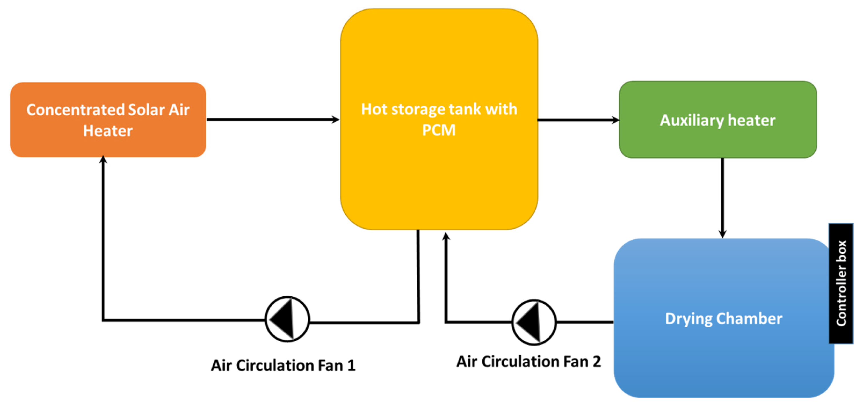
The charging characteristics of an industrial-scale packed-bed thermal storage unit filled with spherical encapsulated phase-change material (PCM) is investigated numerically. The examined storage system can be used in solar powered industrial applications using hot air as a heat transfer fluid, such as high temperature drying processes.
-
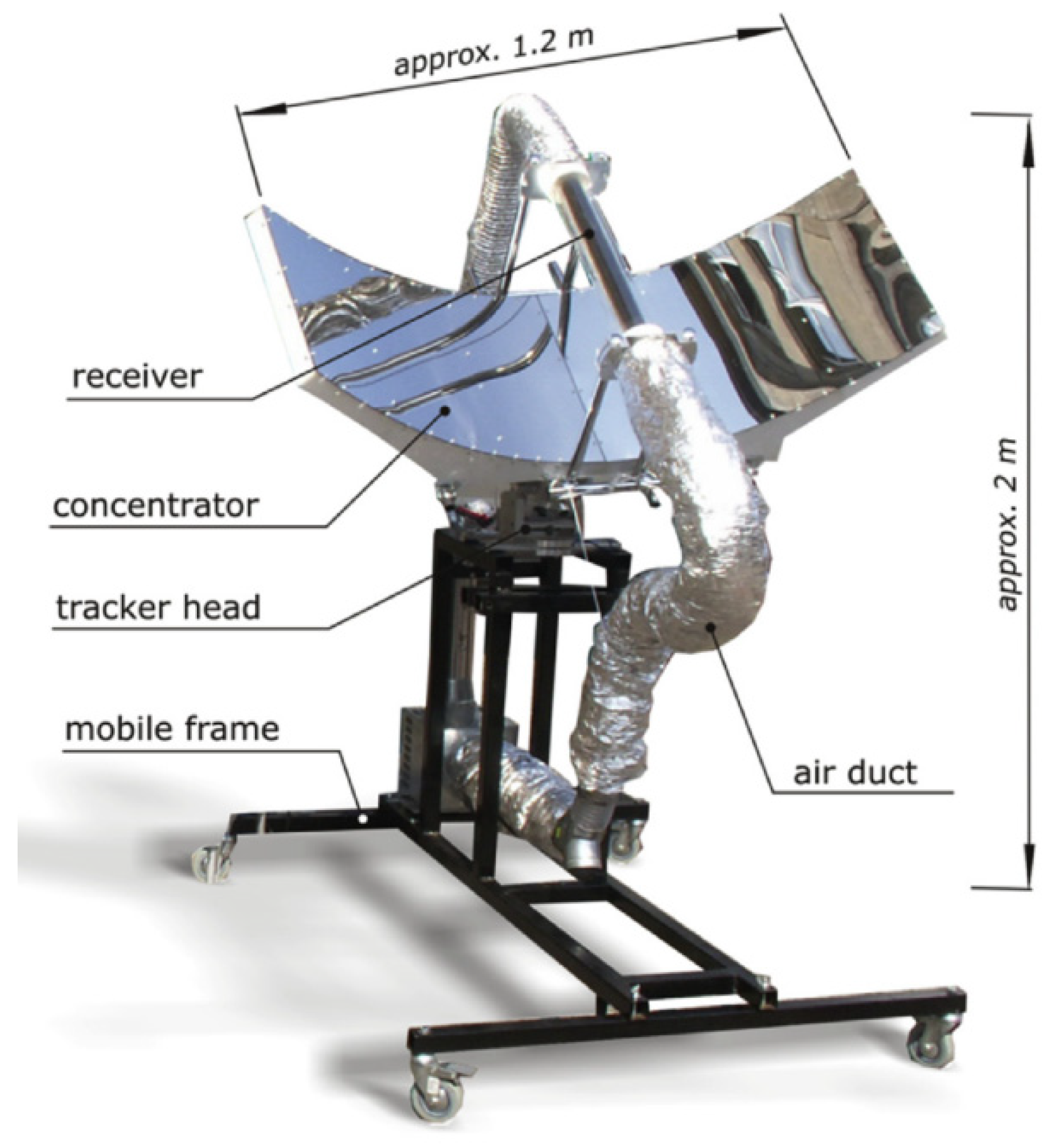
Such systems will render the use of solar air collectors and concentrated solar air collectors more common in heat generation in industrial applications.
-
Detailed parametric studies are carried out to provide key factors for efficient thermal storage when air is utilized as the working fluid. The mathematical model used in the numerical investigation is validated by comparing it to the previous experimental results obtained under the same design and operating conditions.

2. Materials and Methods

The purpose of this work is to study the thermal energy storage characteristics and assess the performance of a vertical hot air storage system filled with spherical phase-change materials. A latent heat storage system can be devised for industrial drying processes, as shown in Figure 2. It should be highlighted that the present study is not concerned with the thermal performance and analysis of the solar collecting system. As can be seen, the industrial drying process utilizes a concentrated solar air heater (CSAH) connected to a latent heat storage system. Hot air is circulated in the solar loop and drying loop via two air fans. An auxiliary (electric) heater can be used to increase the outlet air temperature from the hot storage system to fulfill the set temperatures required by the drying process.
The height of the storage unit and its outer diameter are fixed at 1.8 m and 0.84 m, respectively, implying a thermal storage volume of 1 m3. The phase-change material capsules have a diameter of 0.05 m. The mass flow rates of the heat transfer fluid are varied between 600 and 1000 kg/h (see Table 1). A sketch of the storage system and computational nodes is given in Figure 3.
The developed mathematical model is a 1D heat transfer model consisting of two discretized domains, i.e., working fluid (air) and PCM. Furthermore, the simplifying and reasonable assumptions listed below are considered:
-
The thermophysical properties of PCM are temperature-independent [40];
-
Thermal gradients within the capsules are negligible due to their extremely thin thickness;
-
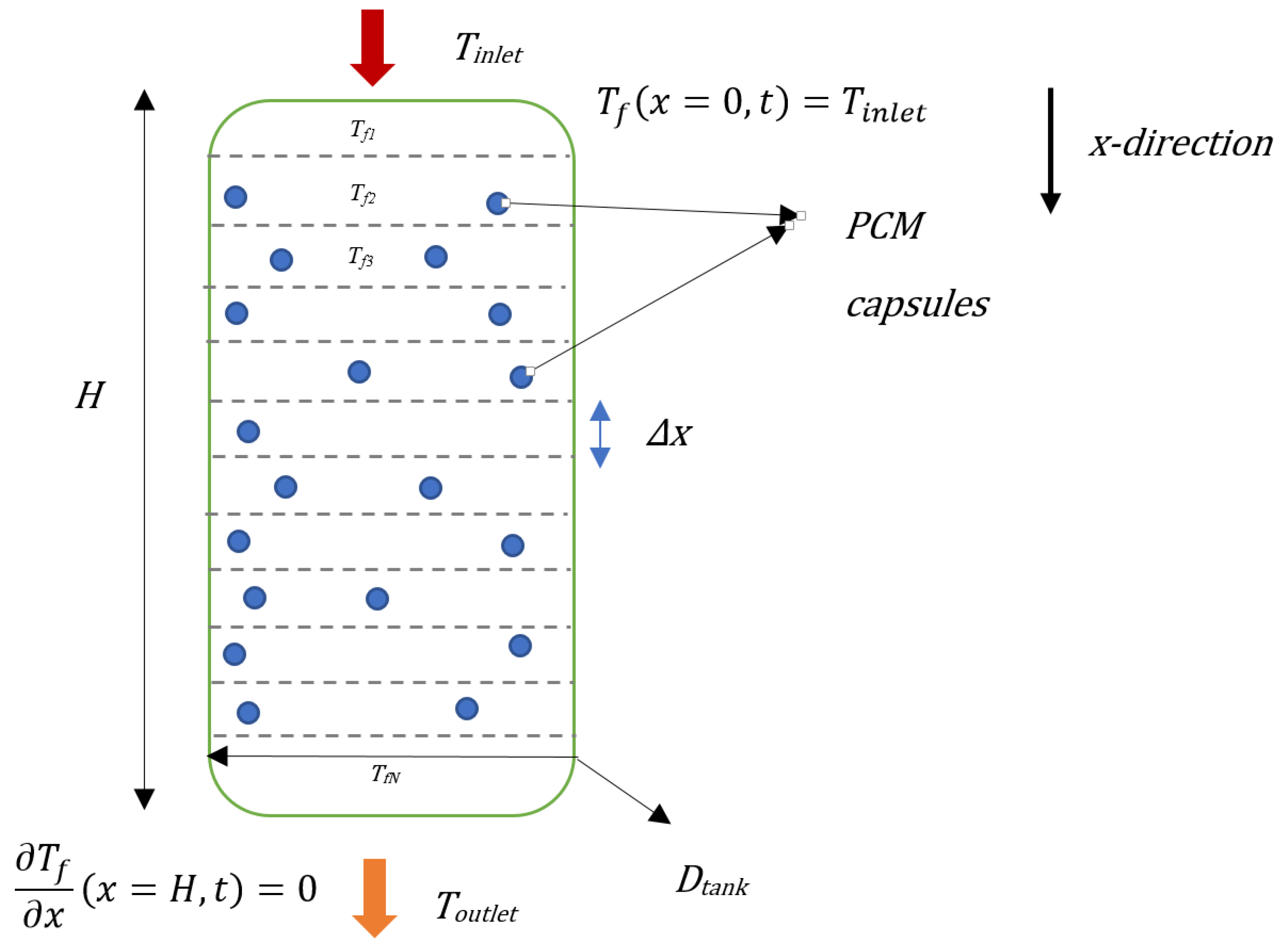
The PCM is uniformly distributed inside the hot storage tank;
-
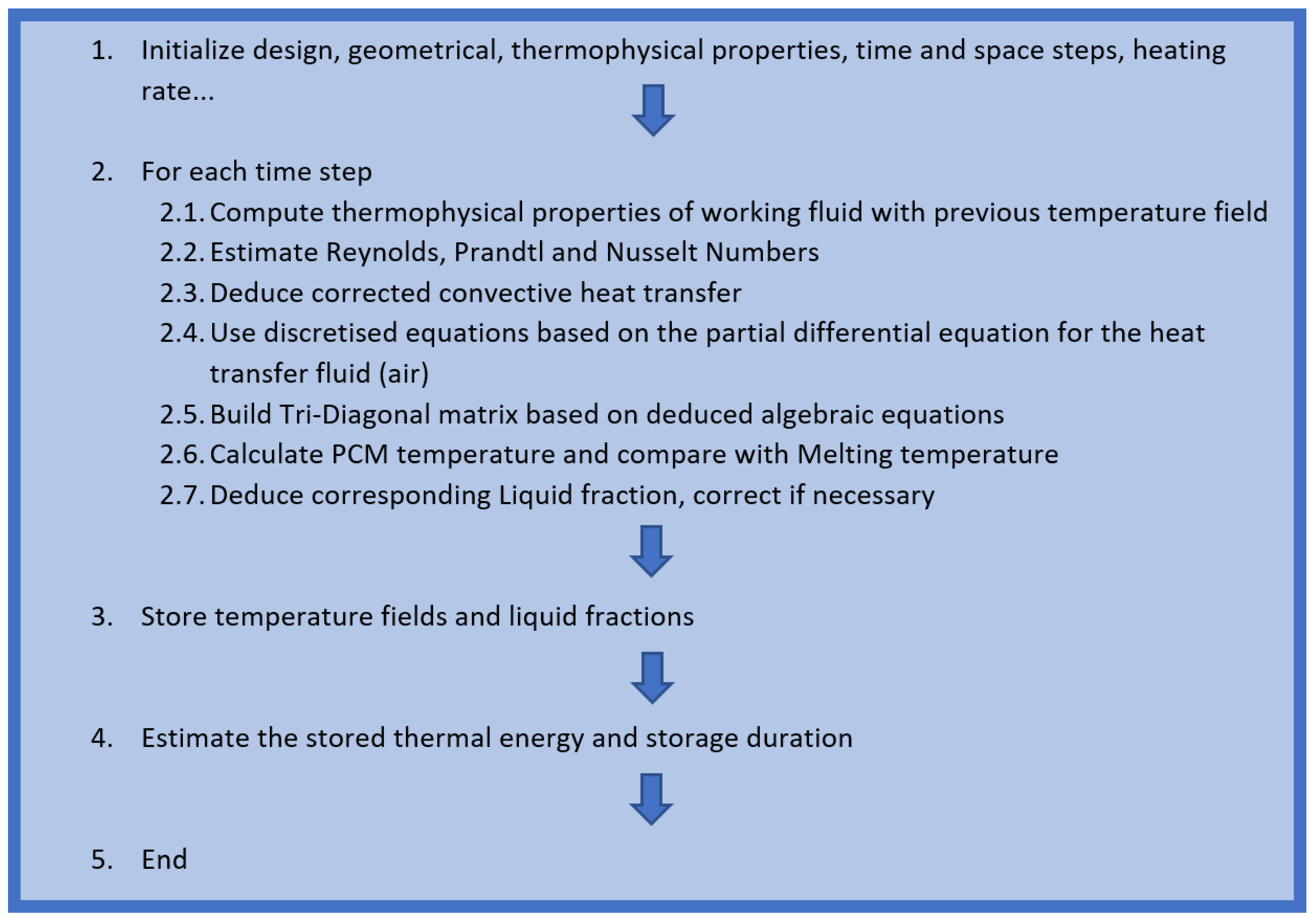
Thermal properties of the working fluid (air) are temperature-dependent and implemented as second-order polynomial functions.
Based on the foregoing assumptions, the energy equation for heat transfer fluid (HTF) is can be written as
ρ f c f ε T f t + u f T f x = k f ε 2 T f x 2 + h e f f a p T P C M T f h w a w T f T s u r r
The velocity of HTF u f and the porosity of the packed bed ε are obtained, respectively by
u f = m f ˙ ε ρ f π R t a n k 2
ε = 1 N P C M V P C M V t a n k
Also, a p represents the superficial capsule surface per packed bed volume, which can be expressed by [41]:
a p = 6 1 ε D
The thermal properties of the heat transfer fluid (air), namely the density ρ f , specific heat capacity c f , and thermal conductivity k f are dependent on the operating temperatures, which are under the form of second-order polynomials, as given by [40].
The PCM heat transfer model is based on a lumped capacitance model as highlighted in the following equation. The lumped capacitance model is appropriate for low Biot number values (Bi < 0.1). In the present study, for the examined parametric studies, the Biot number is higher than 0.1. To justify the use of this approximation, Xu et al. [42] introduced a corrected heat transfer coefficient, allowing for the extended use of the lumped capacitance method for thermal storage systems within a large interval of Biot numbers. According to [42], the corrected heat transfer coefficient in the case of solid spheres in fluid flow is expressed as
h e f f = 1 1 h f + R 5 k s
The term h f , describing the convective heat transfer, is computed and considers the following Nusselt number correlation, as suggested by [40]:
N u = 2 + 1.1 R e 0.6 P r 1 3
Based on the aforementioned assumption and by applying the lumped capacitance model, it is possible to write the energy equation for the PCM as follows:
ρ c P C M 1 ε T P C M t = h e f f a p T P C M T f ρ P C M L f t
ρ c P C M is dependent on the liquid fraction, and the thermal properties of PCM in the liquid and solid states are as follows:
ρ c P C M = ρ P C M s o l i d 1 f c P C M s o l i d + ρ P C M l i q u i d f c P C M l i q u i d
c P C M s o l i d and c P C M l i q u i d are the PCM-specific heat capacities at the solid and liquid states, while ρ P C M s o l i d and ρ P C M l i q u i d are the corresponding densities. L is the PCM latent heat of fusion, and f is the liquid fraction of PCM, which is computed based on Equation (7) during the phase change process, considering that the PCM temperature corresponds to the melting temperature. One should stress that the liquid fraction is corrected at each time step as follows:
f = 0   i f   f < 0 1   i f   f > 1
The previous set of equations is completed by the following initial and boundary conditions.
  • For the heat transfer fluid
T f x , t = 0 = T i n i t i a l x 0 , H
T f x = 0 , t = T i n l e t t > 0
T f x x = H , t = 0   t > 0
  • For the phase change material
T P C M x , t = 0 = T i n i t i a l   x 0 , H
It is important to highlight the inlet temperature used in the boundary conditions (Equation (11)) is time-varying using the following law:
T i n l e t = T i n i t i a l + α t
The symbol α denotes the heating rate (expressed in °C/min) and represents how the inlet temperature of air gradually increases until reaching the charging temperature.
The study of phase change materials (PCMs) for latent storage purposes involves a wide range of materials [43]. These PCMs can be categorized based on their chemical composition and phase change temperature transition. The choice of a specific PCM is dependent on the required temperature range for the targeted application. In this study, adipic acid, which is an organic material with a medium-to-high melting temperature, is used as the phase-change material. Adipic acid is characterized by its good stability, and high latent heat, accessibility at a reasonable price, and melting/solidification temperature, which is suitable for the examined industrial drying process [44]. The thermophysical properties of the employed PCM are listed in Table 2 [40].
To evaluate the charging performance of the latent heat storage filled with encapsulated PCM, the thermal behavior of the modeled system was investigated. The instantaneous charging efficiency, charging time, and cumulative energy stored are assessed for various design and operating scenarios. The instantaneous charging efficiency can be expressed as:
η t = Q ˙ u ( t ) Q ˙ m a x = m ˙ f c f T i n l e t T o u t l e t m ˙ f c f T i n l e t T i n i t i a l
where T i n l e t is the inlet temperature of the air entering the thermal storage unit from the top, and T o u t l e t is the outlet temperature of the air leaving the thermal storage unit.
The second energy index used in the assessment is the charging time t c h a r , which quantifies the amount required to fully charge the system with thermal energy while connected to the heat source. Finally, the cumulative thermal energy stored during the charging process is deduced by
E s t o r e d = t = t 0 t = t 0 + t c h a r Q u ˙ ( t ) d t
This mathematical integral is computed numerically using MATLAB software (version 2014). Figure 4 displays the resolution methodology of the developed model.

3. Results

The above equation system was solved using an implicit formulation based on the Finite Difference approximation. The resulting algebraic equations were solved by performing an inversion of the tri-diagonal matrix at each time step using a MATLAB code.

3.1. Mesh Dependence Test
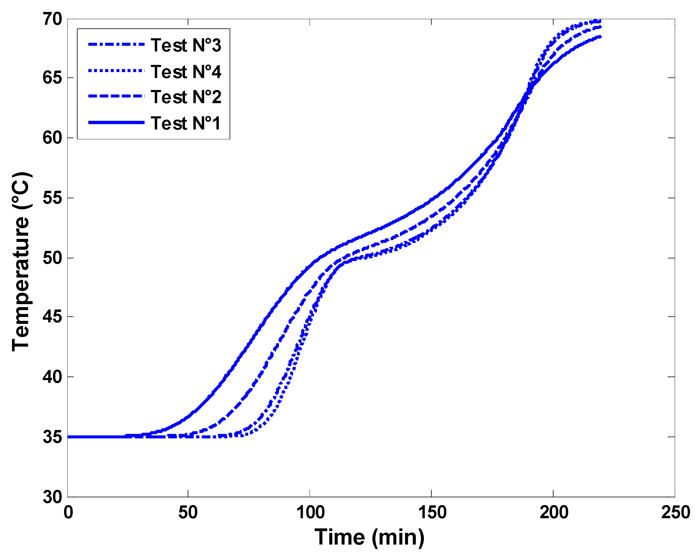
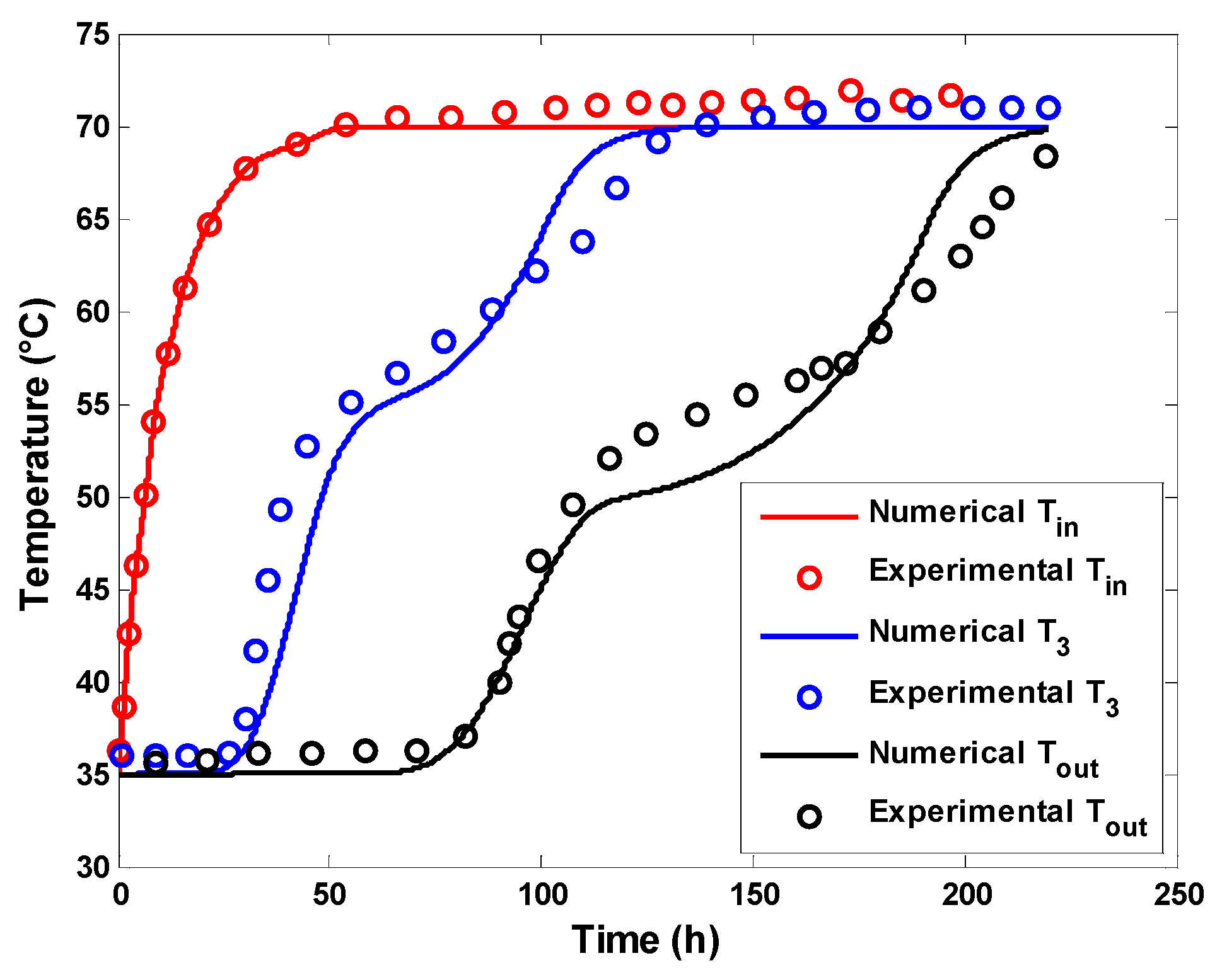
Four different combinations of time steps and quantities of computation nodes were tested in this study, namely Test N°1 (dt = 20 s, N = 10), Test N°2 (dt = 5 s, N = 20), Test N°3 (dt = 1 s, N = 60), and Test N°4 (dt = 0.5 s, N = 100). Figure 5 shows the outlet temperature of the water from the latent heat storage tank for each case. It is worth noting that Test 3 gave satisfactory results without significantly affecting the temperature profile. Test N°3 reduces computational efforts significantly while maintaining very acceptable accuracy compared to Test N°4. Therefore, the time and space grid parameters used in Test N° 3 will be considered in the subsequent numerical investigations.

3.2. Validation

Before utilizing the numerical code further, it is crucial to demonstrate its effectiveness in predicting the thermal behavior of the latent storage tank. In this regard, the experimental results from a study by Kumar et al. [45], in which the effect of adding PCM on the stratification characteristics of a thermal storage system was investigated, were used. The experimental setup consisted of a cylindrical thermal storage tank with an inner diameter of 0.4 m and a height of 1 m, with 92% of the available volume filled with water (corresponding to 0.115 m3). A 0.05 m polyurethane foam layer was used to insulate the tank and prevent heat loss. The experimental setup contained 120 spherical capsules, each with a 75 mm and filled with a commercial PCM with thermal properties, as shown in Table 3 [45].
Experimental studies were conducted for a series of volumetric flow rates and inlet temperatures. A comparison between the numerical model and experimental data for the case of a volumetric flow rate of 1 L/min and an inlet temperature of 70 °C is depicted in Figure 6. It was observed that the model satisfactorily described the thermal profile of the water inside the tank with a maximum error of 3 °C. However, there are potential sources of deviation, such as the localization of PCM, which is assumed to be evenly distributed in the present numerical model, whereas it is mainly located in the upper parts of the tank in the experimental study. Additionally, the model assumes a constant melting temperature of PCM, while the phase change appears to occur within a temperature interval.

3.3. Thermal Behavior of the Latent Storage System

The first set of results focuses on the dynamic thermal behavior of the latent heat storage unit. The various inputs used in numerical experiments are reported in Table 1, which presents the dimensions of the hot air storage system and the characteristics of the used PCM. The temperature profiles at four different positions along the flow direction are presented in Figure 7. It is possible to observe the PCM temperature versus time at the computation nodes ix = 12, ix = 24, ix = 36, and ix = 48, corresponding, respectively, to a distance of 0.4 m, 0.8 m, 1.2 m, and 1.6 m from the hot air entry (top of the storage tank). The air mass flow rate is adjusted to 800 kg/h and the porosity of the packed bed is 0.7, which results in a PCM quantity of 408 kg. The heating rate is fixed at 1.8 °C/min, and the charging temperature is 200 °C. The displayed results indicate that positions near the inlet hot air reach the PCM melting temperature and charging temperature faster. Starting from an initial temperature of 20 °C, the melting process starts at ix = 48 after about 64 min compared to ix = 12. Also, the set charging temperature of 200 °C is reached at the final node (ix = 48) at about 370 min, while it is reached at about 220 min at the computation node (ix = 12). Also, one can observe that the phase change duration is larger for the bottom positions than the nodes on the top. The melting process lasts about two times longer (133 min) at ix = 48 compared to ix = 12. This result is obvious because the thermal power flows from the top of the storage to its bottom side, and the exchange between the heat transfer fluid (air) and upper PCM nodes occurs earlier compared to PCM capsules in the lower parts of the storage unit. It is also possible to distinguish three phases at each computation node, which correspond to the sensible heating of solid PCM, the melting phase of the PCM, and the sensible heating of liquid PCM. These three phases can also be identified in the local liquid fractions displayed in Figure 8 and in the temperature profiles of the working fluid (air) in Figure 9.
At an initial temperature of 20 °C, the PCM is in a solid state (f = 0) and is gradually heated by heat exchange with the hot air flowing across the storage unit. The melting starts after the PCM temperature reaches the melting temperature (151.38 °C). The melting process takes place progressively, and the liquid fraction of the PCM increases gradually from 0 to 1. After the complete melting, any additional heat received from the working fluid will cause the temperature of the melted PCM to increase in the liquid phase. The storage process is finished when the temperature of the heat transfer fluid at the outlet reaches the charging temperature. In Figure 8, thermal power is removed gradually from the heat transfer fluid and is stored by the PCM capsules; approaching the exit of the latent storage (ix = 48), the deviation with respect to the inlet hot air temperature becomes more significant. This results agree well with the findings presented by Grabo et al. [46] for a packed bed latent heat storage unit using non-spherical PCM capsules.

3.4. Parametric Studies

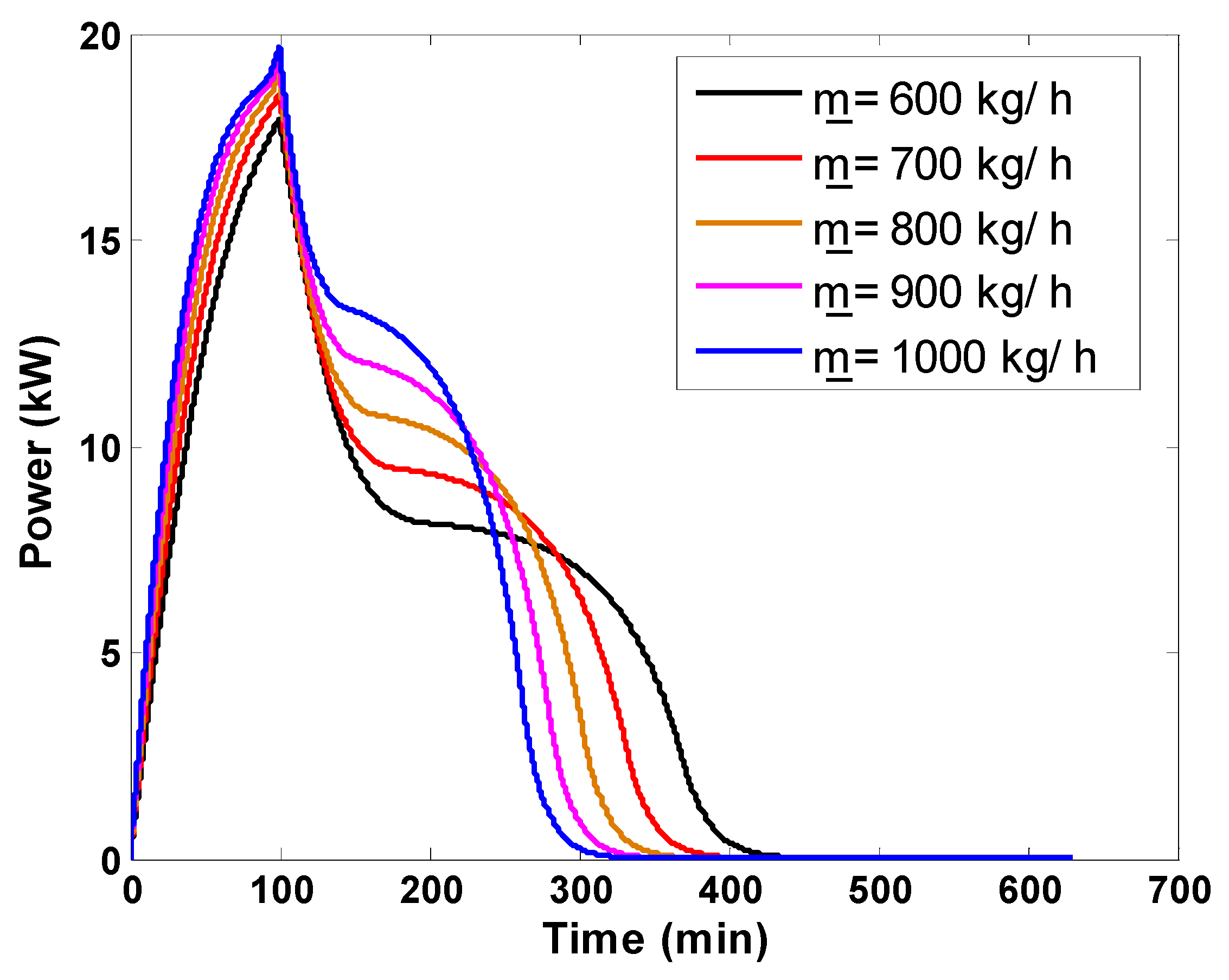
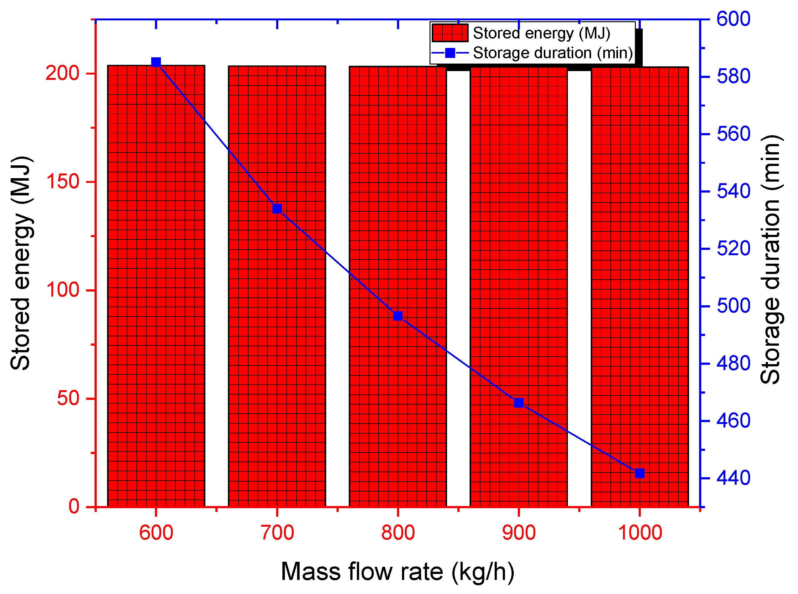
3.4.1. Effect of Mass Flow Rate

The first numerical investigation aimed to determine the effect of the mass flow rate of the working fluid on the main storage performance indexes of the examined latent heat storage unit. The instantaneous useful power stored by the storage unit and the thermal efficiency are presented in Figure 10 and Figure 11, respectively. The useful power increases from 0 kW (the beginning of the charging process) and reaches peak values that coincide with the maximum temperature difference between the inlet and outlet air temperature during the sensible storage process. After achieving this maximum power, the difference between inlet and outlet temperatures drops rapidly to reach its minimum value during the sensible charging process. During the charging process, high mass flow rates achieve a given thermal power storage earlier because they are responsible for elevated thermal power flows. Immediately after this point, the melting process starts. Throughout the melting process, this temperature difference continues in a decreasing trend and very slowly highlights the heat transfer during the phase transition of the PCM. This behavior results in a decreasing trend of the useful power. By the end of the melting process, the outlet temperature of the working fluid reaches the charging temperature rapidly, causing a second rapid drop in the useful power, which vanishes at the end of the charging process. Higher flow rates complete the whole charging process earlier. In terms of thermal efficiency, low mass flow rates operate better than high flow rates.
For mass flow rates ranging from 600 to 1000 kg/h and for the design specifications presented earlier, the cumulative energy stored is similar and is about 203 kJ (see Figure 12). In fact, the cumulative energy stored by the PCM can be analytically written as a function of only tank volume, porosity, thermophysical properties of the PCM, and fluid inlet and exit temperatures. However, the storage time can be reduced from 582 min for 600 kg/h to 440 min for 1000 kg/h. Based only on these two metrics, it is not possible to recommend an optimum flow rate unless taking into account the effect of pumping requirements as well. The mass flow rate of the HTF should be optimized to ensure that heat is transferred efficiently into the PCM without causing excessive pressure drops or flow instability.

3.4.2. Effect of Charging Temperature

The effect of charging temperature was evidenced by running simulations for five charging temperatures ranging from 160 °C to 240 °C, where the melting temperature of the used PCM is within the investigated range. The cumulative stored thermal energy is higher, and storage durations are lower for high charging temperatures (see Figure 13), which confirms that high-temperature collectors are more suitable for the storage process. Here, an economic investigation of the heat generation system should be applied to judge the best technology that not only maximizes storage performances, but also reduces heat generation costs. The storage duration drops significantly from around 1150 min for a charging temperature of 160 °C to 470 min for a charging temperature of 240 °C. Also, the highest charging temperature allows for the storage of about 50 MJ surplus heat compared to a charging temperature of 160 °C. One should add that increased charging temperatures can pose some constraints, such as material compatibility (generally due to possible PCM degradation) and thermal stresses, that can cause structural deformation and failure during the storage unit’s lifespan.

3.4.3. Effect of Bed Porosity

The bed porosity significantly affects the storage process since it depends on the total quantity of PCM used. The porosity was changed from 0.5 to 0.9, and computations were performed for a mass flow rate of 800 kg/h and a charging temperature of 200 °C (see Figure 14). The corresponding PCM masses are 500 kg and 1000 kg. A low porosity suggests higher PCM quantity in the storage tank, which implies a higher capacity for thermal storage. The better scenario is achieved for a porosity of 0.5, for which the thermal energy stored is around 344 MJ. In turn, for this porosity, the PCM requires more time to complete the charging process (about 610 min). One should highlight that identifying the optimum porosity will require estimating the pressure loss across the tank as well. The optimum porosity should satisfy the best compromise between high thermal energy stored, minimum storage duration, and low pressure losses.

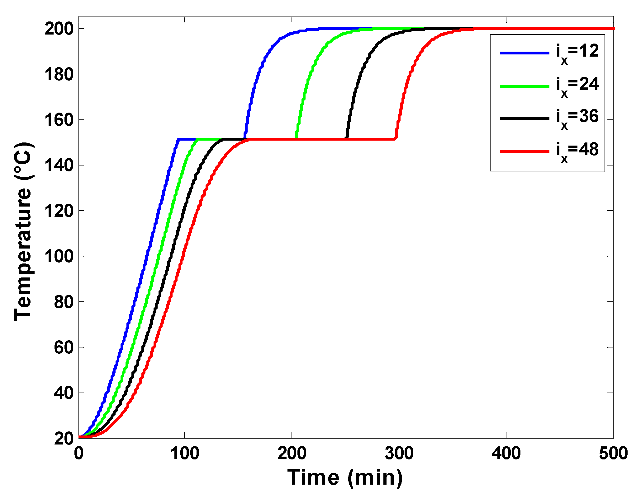
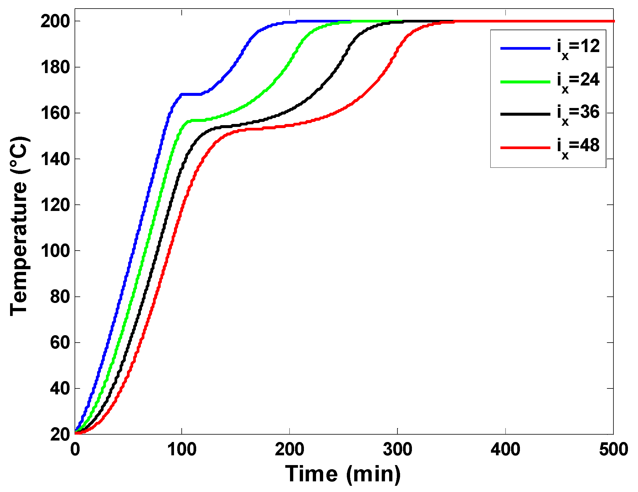
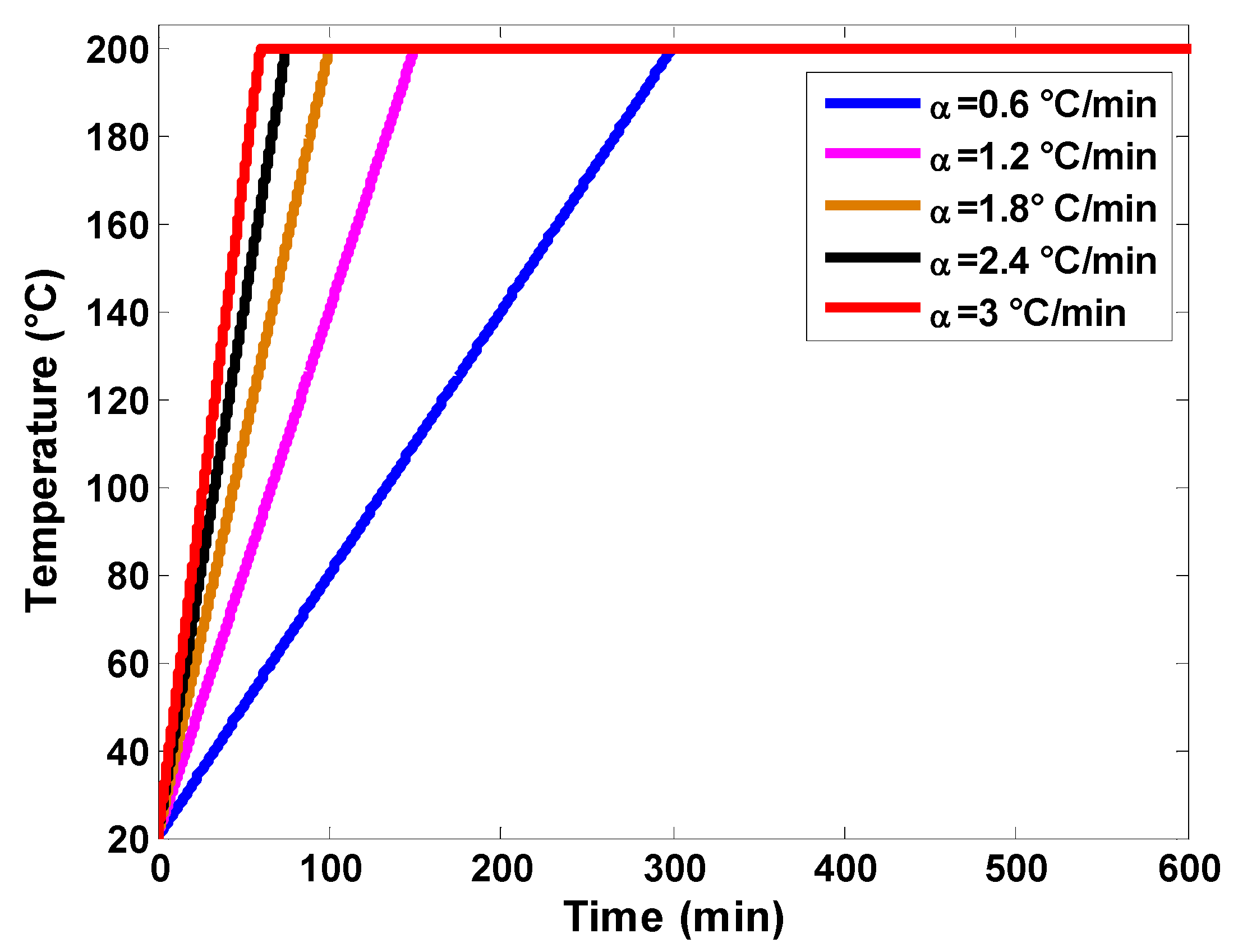
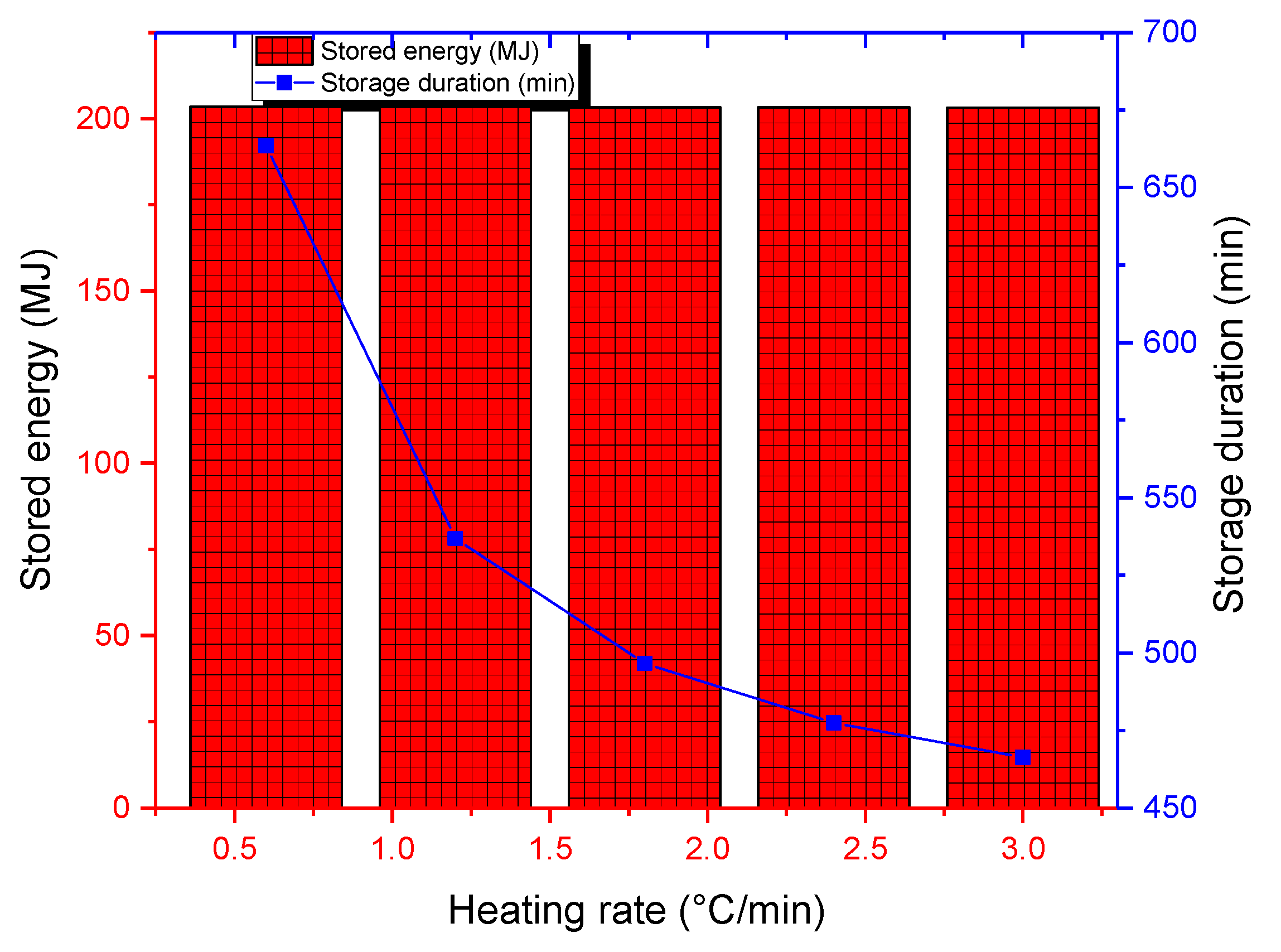
3.4.4. Effect of Heating Rate

The last parametric study deals with the effect of the heating rate on storage performance. Inlet temperatures for the examined heating rates are visualized graphically in Figure 15. The heating rate defines how rapidly the charging temperature is achieved. The numerical tests were carried out for a bed porosity of 0.7, a fluid mass flow rate of 800 kg/h, and a charging temperature of 200 °C. While the cumulative thermal energy stored remains almost constant, high rating rates allow for lower storage durations (see Figure 16). For the rating rate of 3 °C/min, storage duration is about 460 min compared to 660 min for a rating rate of 0.5 °C/min. In real implementation scenarios, inlet temperature variation will depend on the solar collector technology and design.

4. Conclusions

This paper presents a numerical investigation of a packed bed latent heat storage system using an encapsulated phase-change material (PCM) for an industrial drying process with the potential to be combined with concentrated Solar Air Heaters (CSAH). The mathematical model used to simulate the storage unit is based on heat transfer equations for both heat transfer fluid (air) and the encapsulated PCM. Energy equations were solved numerically using the Finite Difference Method and validated with experimental data from previous studies. Based on the obtained results, it was found that the system’s performance was highly dependent on the mass flow rate of the working fluid and charging temperature. A high charging temperature results in shorter storage duration and higher energy storage capacity. The porosity of the storage bed is an important parameter that affects both the storage capacity and storage duration, with lower porosity resulting in higher storage capacity but longer charging times. Moreover, the heating rate affects the storage duration, with higher heating rates resulting in shorter storage times but almost constant thermal energy storage.
The author recommends further investigation into different phase-change materials with varying thermophysical properties and incorporating a realistic industrial heat load. He also suggests optimizing the storage technique economically and energetically through multi-criteria analysis, especially given that some of the design and operating parameters have conflicting effects on the investigated performance indices. Establishing an experimental setup for the proposed storage system can also be highlighted as a perspective work.

Funding

This research received no external funding.

Data Availability Statement

Data available upon request due to restrictions, e.g., privacy or ethical.

Conflicts of Interest

The author declares no conflict of interest.

Nomenclature

apSuperficial capsule surface (m−1)
cSpecific heat (J·kg−1·K−1)
DDiameter (m)
EEnergy (J)
HHeight tank (m)
LLatent heat (J·kg−1)
PrPrandtl number
RRadius (m)
ReReynolds number
tTime (s)
TTemperature (°C)
uVelocity (m·s−1)
hConvective transfer coefficient (W·m−2·K−1)
VVolume (m3)
xPosition along the direction of the tank (m)
Greek letters
fLiquid fraction (-)
ρDensity (kg m−3)
εPorosity (-)
ηEfficiency (-)
Subscripts
effeffective
HTFHeat transfer fluid
mMelting
Abbreviations
CSAHConcentrated Solar Air Heater
PCMPhase Change Material

References

  1. Emissions Gap Report 2022. Available online: https://www.unep.org/resources/emissions-gap-report-2022 (accessed on 30 April 2023).
  2. Clean and Efficient Heat for Industry–Analysis-IEA. Available online: https://www.iea.org/commentaries/clean-and-efficient-heat-for-industry (accessed on 30 April 2023).
  3. Andrei, M.; Thollander, P.; Pierre, I.; Gindroz, B.; Rohdin, P. Decarbonization of industry: Guidelines towards a harmonized energy efficiency policy program impact evaluation methodology. Energy Rep. 2021, 7, 1385–1395. [Google Scholar] [CrossRef]
  4. Hayashi, D. Harnessing innovation policy for industrial decarbonization: Capabilities and manufacturing in the wind and solar power sectors of China and India. Energy Res. Soc. Sci. 2020, 70, 101644. [Google Scholar] [CrossRef]
  5. Zhang, K.; Lau, H.C.; Bokka, H.K.; Hadia, N.J. Decarbonizing the power and industry sectors in India by carbon capture and storage. Energy 2022, 249, 123751. [Google Scholar] [CrossRef]
  6. Martins, F.; Moura, P.; de Almeida, A.T. The Role of Electrification in the Decarbonization of the Energy Sector in Portugal. Energies 2022, 15, 1759. [Google Scholar] [CrossRef]
  7. Bleischwitz, R.; Yang, M.; Huang, B.; Xiaozhen, X.U.; Zhou, J.; McDowall, W.; Andrews-Speed, P.; Liu, Z.; Yong, G. The circular economy in China: Achievements, challenges and potential implications for decarbonization. Resour. Conserv. Recycl. 2022, 183, 106350. [Google Scholar] [CrossRef]
  8. Oberthür, S.; Khandekar, G.; Wyns, T. Global governance for the decarbonization of energy-intensive industries: Great potential underexploited. Earth Syst. Gov. 2021, 8, 100072. [Google Scholar] [CrossRef]
  9. IEA. Tracking Industry 2021—Analysis—IEA; IEA: Paris, France, 2021. [Google Scholar]
  10. Martín, M. Challenges and opportunities of Solar thermal energy towards a sustainable chemical industry. Comput. Chem. Eng. 2022, 165, 107926. [Google Scholar] [CrossRef]
  11. Kumar, K.R.; Chaitanya, N.V.V.K.; Kumar, N.S. Solar thermal energy technologies and its applications for process heating and power generation–A review. J. Clean. Prod. 2021, 282, 125296. [Google Scholar] [CrossRef]
  12. Gil, J.D.; Topa, A.; Álvarez, J.D.; Torres, J.L.; Pérez, M. A review from design to control of solar systems for supplying heat in industrial process applications. Renew. Sustain. Energy Rev. 2022, 163, 112461. [Google Scholar] [CrossRef]
  13. de Sá, B.; Filho, V.C.P.; Tadrist, L.; Passos, J.C. Direct steam generation in linear solar concentration: Experimental and modeling investigation—A review. Renew. Sustain. Energy Rev. 2018, 90, 910–936. [Google Scholar] [CrossRef]
  14. Azouzoute, A.; El Ydrissi, M.; Elmaazouzi, Z.; Benhaddou, M.; Salihi, M.; Hajjaj, C.; Garoum, M. Thermal production and heat cost analysis of the potential of solar concentrators for industrial process applications: A case study in six sites in Morocco. Sci. Afr. 2021, 12, e00765. [Google Scholar] [CrossRef]
  15. Famiglietti, A.; Lecuona, A.; Ibarra, M.; Roa, J. Turbo-assisted direct solar air heater for medium temperature industrial processes using Linear Fresnel Collectors. Assessment on daily and yearly basis. Energy 2021, 223, 120011. [Google Scholar] [CrossRef]
  16. Cetina-Quiñones, J.; Bassam, A.; Carrillo, J.G.; Pérez-Quintana, I.; Ricalde, L.J.; San-Pedro, L. 4E analysis for the implementation of parabolic trough solar collectors in Mexican dairy industry sector: An optimization approach including passive heat transfer methods. Sustain. Energy Technol. Assess. 2022, 53, 102532. [Google Scholar] [CrossRef]
  17. Kylili, A.; Fokaides, P.A.; Ioannides, A.; Kalogirou, S. Environmental assessment of solar thermal systems for the industrial sector. J. Clean. Prod. 2018, 176, 99–109. [Google Scholar] [CrossRef]
  18. Lamrani, B.; Kuznik, F.; Ajbar, A.; Boumaza, M. Energy analysis and economic feasibility of wood dryers integrated with heat recovery unit and solar air heaters in cold and hot climates. Energy 2021, 228, 120598. [Google Scholar] [CrossRef]
  19. Kasperski, J.; Nemś, M. Investigation of thermo-hydraulic performance of concentrated solar air-heater with internal multiple-fin array. Appl. Therm. Eng. 2013, 58, 411–419. [Google Scholar] [CrossRef]
  20. Arunkumar, H.S.; Karanth, K.V.; Kumar, S. Review on the design modifications of a solar air heater for improvement in the thermal performance. Sustain. Energy Technol. Assess. 2020, 39, 100685. [Google Scholar] [CrossRef]
  21. Wang, P.-Y.; Guan, H.-Y.; Liu, Z.-H.; Wang, G.-S.; Zhao, F.; Xiao, H.-S. High temperature collecting performance of a new all-glass evacuated tubular solar air heater with U-shaped tube heat exchanger. Energy Convers. Manag. 2014, 77, 315–323. [Google Scholar] [CrossRef]
  22. Kabeel, E.; Abdelgaied, M.; Sathyamurthy, R. A comprehensive investigation of the optimization cooling technique for improving the performance of PV module with reflectors under Egyptian conditions. Sol. Energy 2019, 186, 257–263. [Google Scholar] [CrossRef]
  23. Nemś, M.; Kasperski, J. Experimental investigation of concentrated solar air-heater with internal multiple-fin array. Renew. Energy 2016, 97, 722–730. [Google Scholar] [CrossRef]
  24. Ekka, J.P.; Kumar, D. A review of industrial food processing using solar dryers with heat storage systems. J. Stored Prod. Res. 2023, 101, 102090. [Google Scholar] [CrossRef]
  25. Koçak, B.; Fernandez, A.I.; Paksoy, H. Review on sensible thermal energy storage for industrial solar applications and sustainability aspects. Sol. Energy 2020, 209, 135–169. [Google Scholar] [CrossRef]
  26. Manikandan, G.K.; Iniyan, S.; Goic, R. Enhancing the optical and thermal efficiency of a parabolic trough collector—A review. Appl. Energy 2019, 235, 1524–1540. [Google Scholar] [CrossRef]
  27. Andharia, J.K.; Solanki, J.B.; Maiti, S. Performance evaluation of a mixed-mode solar thermal dryer with black pebble-based sensible heat storage for drying marine products. J. Energy Storage 2023, 57, 106186. [Google Scholar] [CrossRef]
  28. Li, Y.-C.; Zhang, L.; Feng, B. Optimization of thermal performance of high temperature sensible heat thermal energy storage system for direct steam generation: A simulation work. Appl. Therm. Eng. 2022, 217, 119225. [Google Scholar] [CrossRef]
  29. Zhang, S.; Mancin, S.; Pu, L. A review and prospective of fin design to improve heat transfer performance of latent thermal energy storage. J. Energy Storage 2023, 62, 106825. [Google Scholar] [CrossRef]
  30. Liu, W.; Bie, Y.; Xu, T.; Cichon, A.; Krolczyk, G.; Li, Z. Heat transfer enhancement of latent heat thermal energy storage in solar heating system: A state-of-the-art review. J. Energy Storage 2022, 46, 103727. [Google Scholar] [CrossRef]
  31. Sharma, A.; Pitchumani, R.; Chauhan, R. Solar air heating systems with latent heat storage—A review of state-of-the-art. J. Energy Storage 2022, 48, 104013. [Google Scholar] [CrossRef]
  32. Zakri, W.; Mellouli, S.; Fageehi, Y. Performance Assessment of Three Latent Heat Storage Designs for a Solar Hot Water Tank. Sustainability 2023, 15, 640. [Google Scholar] [CrossRef]
  33. Bazri, S.; Badruddin, I.A.; Usmani, A.Y.; Khan, S.A.; Kamangar, S.; Naghavi, M.S.; Mallah, A.R.; Abdelrazek, A.H. Thermal hysteresis analysis of finned-heat-pipe-assisted latent heat thermal energy storage application for solar water heater system. Case Stud. Therm. Eng. 2022, 40, 102490. [Google Scholar] [CrossRef]
  34. Yari, S.; Safarzadeh, H.; Bahiraei, M. Experimental study of storage system of a solar water heater equipped with an innovative absorber spherical double-walled tank immersed in a phase change material. J. Energy Storage 2023, 61, 106782. [Google Scholar] [CrossRef]
  35. Chopra, K.; Pathak, A.K.; Tyagi, V.; Pandey, A.K.; Anand, S.; Sari, A. Thermal performance of phase change material integrated heat pipe evacuated tube solar collector system: An experimental assessment. Energy Convers. Manag. 2020, 203, 112205. [Google Scholar] [CrossRef]
  36. Munir, Z.; Roman, F.; Niazi, B.M.K.; Mahmood, N.; Munir, A.; Hensel, O. Thermal analysis of a solar latent heat storage system using Scheffler concentrator for agricultural applications. Appl. Therm. Eng. 2022, 218, 119230. [Google Scholar] [CrossRef]
  37. Elfeky, K.E.; Mohammed, A.G.; Wang, Q. Thermo-economic evaluation of PCM layer thickness change on the performance of the hybrid heat storage tank for concentrating solar power plants. Energy 2022, 253, 124128. [Google Scholar] [CrossRef]
  38. Liu, Z.; Liu, Z.; Guo, J.; Wang, F.; Yang, X.; Yan, J. Innovative ladder-shaped fin design on a latent heat storage device for waste heat recovery. Appl. Energy 2022, 321, 119300. [Google Scholar] [CrossRef]
  39. Du, K.; Calautit, J.; Eames, P.; Wu, Y. A state-of-the-art review of the application of phase change materials (PCM) in Mobilized-Thermal Energy Storage (M-TES) for recovering low-temperature industrial waste heat (IWH) for distributed heat supply. Renew. Energy 2021, 168, 1040–1057. [Google Scholar] [CrossRef]
  40. Guo, W.; He, Z.; Zhang, Y.; Zhang, P. Thermal performance of the packed bed thermal energy storage system with encapsulated phase change material. Renew. Energy 2022, 196, 1345–1356. [Google Scholar] [CrossRef]
  41. Kousksou, T.; Bruel, P. Encapsulated phase change material under cyclic pulsed heat load. Int. J. Refrig. 2010, 33, 1648–1656. [Google Scholar] [CrossRef]
  42. Xu, B.; Li, P.-W.; Chan, C.L. Extending the validity of lumped capacitance method for large Biot number in thermal storage application. Sol. Energy 2012, 86, 1709–1724. [Google Scholar] [CrossRef]
  43. Javadi, F.S.; Metselaar, H.S.C.; Ganesan, P. Performance improvement of solar thermal systems integrated with phase change materials (PCM), a review. Sol. Energy 2020, 206, 330–352. [Google Scholar] [CrossRef]
  44. Fatahi, H.; Claverie, J.; Poncet, S. Experimental investigation of the rheological and phase change behavior of adipic acid as a phase change material (PCM) for thermal energy storage at 150 °C. Thermochim. Acta 2022, 711, 179206. [Google Scholar] [CrossRef]
  45. Kumar, G.S.; Nagarajan, D.; Chidambaram, L.A.; Kumaresan, V.; Ding, Y.; Velraj, R. Role of PCM addition on stratification behaviour in a thermal storage tank—An experimental study. Energy 2016, 115, 1168–1178. [Google Scholar] [CrossRef]
  46. Grabo, M.; Acar, E.; Kenig, E.Y. Modeling and improvement of a packed bed latent heat storage filled with non-spherical encapsulated PCM-Elements. Renew. Energy 2021, 173, 1087–1097. [Google Scholar] [CrossRef]
Figure 1. Prototype of the CSAH system investigated by [23].
Sustainability 15 13254 g001
Figure 2. Illustration of an industrial drying process using a latent heat storage system.
Sustainability 15 13254 g002
Figure 3. Physical model of the latent heat storage system.
Sustainability 15 13254 g003
Figure 4. Resolution methodology of the physical model.
Sustainability 15 13254 g004
Figure 5. Mesh dependence test with respect to the outlet air temperature exiting the storage.
Sustainability 15 13254 g005
Figure 6. Comparison between simulation results and experimental values by Kumar et al. [45].
Sustainability 15 13254 g006
Figure 7. PCM temperature profile at four different computation nodes.
Sustainability 15 13254 g007
Figure 8. Liquid fraction of the PCM at four different computation nodes.
Sustainability 15 13254 g008
Figure 9. Temperature profile of the heat transfer fluid at four different computation nodes.
Sustainability 15 13254 g009
Figure 10. Thermal power variation of packed bed storage tank for various mass flow rates.
Sustainability 15 13254 g010
Figure 11. Thermal efficiency variation of packed bed storage tank for various mass flow rates.
Sustainability 15 13254 g011
Figure 12. Cumulative stored energy and storage duration for various mass flow rates.
Sustainability 15 13254 g012
Figure 13. Cumulative stored energy and storage duration for various charging temperatures.
Sustainability 15 13254 g013
Figure 14. Cumulative stored energy and storage duration for various bed porosities.
Sustainability 15 13254 g014
Figure 15. Inlet temperatures of air for various heating rates.
Sustainability 15 13254 g015
Figure 16. Cumulative stored energy and storage duration for various heating rates.
Sustainability 15 13254 g016
Table 1. Main geometrical, design, and operating parameters of the latent storage unit.
ParameterValue
Height of the storage unit (m)1.8 m
External diameter of the storage unit (m)0.84 m
Diameter of PCM capsules (m)0.05 m
Number of PCM capsules2260
Mass flow rate600–1000 kg/h
Charging temperature (°C)160–240
Table 2. Thermophysical properties of the PCM used in the simulation study [40].
Thermophysical PropertyValue
Density at solid state (kg/m3)1360
Density at liquid state (kg/m3)1088
Solid specific heat (J/kg K)1590
Liquid specific heat (J/kg K)2260
Latent heat (J/kg)241,000
Melting temperature (°C)151.38
Table 3. Thermophysical properties of the PCM used in the experiments by Kumar et al. [45].
Thermophysical PropertyValue
Density at solid state (kg/m3)980
Density at liquid state (kg/m3)875
Solid specific heat (J/kg K)2000
Liquid specific heat (J/kg K)2400
Latent heat (J/kg)173,500
Melting temperature (°C)45–50
Disclaimer/Publisher’s Note: The statements, opinions and data contained in all publications are solely those of the individual author(s) and contributor(s) and not of MDPI and/or the editor(s). MDPI and/or the editor(s) disclaim responsibility for any injury to people or property resulting from any ideas, methods, instructions or products referred to in the content.

