Article

Multi-Material Additive Manufacturing: Creating IN718-AISI 316L Bimetallic Parts by 3D Printing, Debinding, and Sintering

1
Department of Engineering and Management, University of Padova, 36100 Vicenza, Italy
2
Department of Industrial Engineering, University of Padova, 35131 Padua, Italy
3
Refractories, Ceramics and Building Materials Department, National Research Centre, Cairo 12622, Egypt
4
Department of Civil, Environmental and Architectural Engineering, University of Padova, 35131 Padua, Italy
*
Authors to whom correspondence should be addressed.
Sustainability 2023, 15(15), 11911; https://doi.org/10.3390/su151511911
Submission received: 28 June 2023 / Revised: 24 July 2023 / Accepted: 31 July 2023 / Published: 2 August 2023

Abstract

:
Allowing for complex shape and low energy consumption, 3D printing, debinding, and sintering (PDS) is a promising and cost-effective additive manufacturing (AM) technology. Moreover, PDS is particularly suitable for producing bimetallic parts using two metal/polymer composite filaments in the same nozzle, known as co-extrusion, or in different nozzles, in a setup called bi-extrusion. The paper describes a first attempt to produce bimetallic parts using Inconel 718 and AISI 316L stainless steel via PDS. The primary goal is to assess the metallurgical characteristics, part shrinkage, relative density, and the interdiffusion phenomenon occurring at the interface of the two alloys. A first set of experiments was conducted to investigate the effect of deposition patterns on the above-mentioned features while keeping the same binding and sintering heat treatment. Different sintering temperatures (1260 °C, 1300 °C, and 1350 °C) and holding times (4 h and 8 h) were then investigated to improve the density of the printed parts. Co-extruded parts showed a better dimensional stability against the variations induced by the binding and sintering heat treatment, compared to bi-extruded samples. In co-extruded parts, shrinkage depends on scanning strategy; moreover, the higher the temperature and holding time of the sintering heat treatment, the higher the density reached. The work expands the knowledge of PDS for metallic multi-materials, opening new possibilities for designing and utilizing functionally graded materials in optimized components. With the ability to create intricate geometries and lightweight structures, PDS enables energy savings across industries, such as the aerospace and automotive industries, by reducing component weight and enhancing fuel efficiency. Furthermore, PDS offers substantial advantages in terms of resource efficiency, waste reduction, and energy consumption compared to other metal AM technologies, thereby reducing environmental impact.

1. Introduction

In recent years, metal additive manufacturing (AM) experienced significant and rapid growth, driven by the realization of its exceptional inherent capabilities in fabricating parts with highly intricate geometries and achieving cost savings compared to conventional manufacturing methods. This is especially evident when dealing with high-performance materials such as titanium and nickel-based alloys, making AM a preferred choice for various industrial applications. Razavi et al. [1], investigated the fatigue strength of Ti-6Al-4V smooth and blunt V-notched samples produced via the selective laser melting (SLM) process finding a low notch sensitivity of the material tested. Ferro et al. [2] described the main phenomena involved in powder bed fusion AM processes via numerical simulation and proposed a modified volumetric energy density approach to calibrate process parameters aimed at minimizing AM-induced porosity [3]. The most studied processes, also known as mainstream commercial metal AM technologies, include powder bed fusion (PBF) [4], directed energy deposition (DED) [5], binder jetting (BJ) [6], and other emerging technologies, such as ultrasonic additive manufacturing (UAM) [7] and metal droplet printing (MDP) [8]. In PBF and DED processes, a heat source is utilized to consolidate the powdered metal material layer by layer (both well known as low-efficiency and high-energy demanding heating sources). These heat sources are well known for their low efficiency and high energy demand. Ultrasonic energy, despite its high energy consumption, is employed in UAM to consolidate the feeding of metal foils or tapes. Due to the substantial investments required for the facilities in all these processes, there is a strong drive to explore alternative AM solutions that are both more cost-effective and energy-efficient.
In this context, 3D printing debinding and sintering (PDS) AM emerge as promising alternatives to the conventional technologies mentioned above [9]. In practice, fused filament fabrication (FFF) utilizes a polymer-based filament that is heavily infused with metal particles to create a green part. Subsequently, the polymer binder is chemically and/or thermally removed in a debinding process to obtain the ‘brown part,’ which is then densified through a sintering heat treatment [10]. This AM process is known in literature by different names, such as bound metal deposition (BMD) [11], fused deposition modeling and sintering (FDMS) [12], atomic diffusion additive manufacturing (ADAM) [13], and printing–debinding–sintering (PDS) [14]. Since the energy required for deposition is closely tied to the properties of the polymer binder, and the debinding and sintering heat treatments can be performed on entire batches, PDS holds great promise for the large-scale production of metal parts at a relatively high fabrication rate. Especially in small batch sizes, the literature shows that AM is an environmentally friendly and cost-effective approach that is able to reduce environmental and social impact, to minimize cost, waste, and tooling, to increase design flexibility, customization and product performance, and to enable on-demand production, reducing transportation and storage [15,16,17,18]. In the context of metal AM, the PDS process offers advantages in terms of easy handling and cost efficiency compared to powder-based processes [19]. It is also recognized for its low energy consumption, whereas powder bed fusion (PBF) is considered to be the least energy-efficient process [20]. Furthermore, the use of feedstock materials in the form of polymer-bound metal powders in the PDS process prevents the loss of metal powders, thus eliminating the inherent risks associated with handling fine metallic particles [20]. Moreover, leveraging the shape and material complexity enabled by AM, along with design tools such as topology optimization and generative design, enables the creation of highly efficient structures that improve factors such as weight, stress distribution, costs, and environmental impact [21,22,23], leading to energy savings in various industries, such as the aerospace and automotive industries, by improving fuel efficiency [24,25]. However, it is crucial to identify advantageous strategies for disposal and recycling to address the end-of-life stage of AM components.
Despite the potential benefits, research efforts on the PDS process for metal AM are still in the early stages, and several steps are necessary to ensure the future development and industrialization of PDS. Firstly, a comprehensive manufacturing technology cycle should be established, encompassing accessible materials and equipment. Secondly, it is important to address product quality issues and strive for flawlessness. The next stage involves optimizing technology in terms of cost, quality, and accuracy. Additionally, a sufficient level of control and analysis of metallurgical characteristics and microstructure must be established. This includes enhancing mechanical properties such as tensile strength to enable a wider range of applications. Lastly, the development of affordable commercial materials, such as filaments, binders, and powders, should be prioritized [26]. Recent literature highlights pioneering works on stainless steels (SS) or Inconel 718 (IN718). Liu et al. [12] examined the metallurgical and mechanical properties of 316L SS parts manufactured through FDMS, sintering at a temperature of 1360 °C for 2 h, with argon gas serving as a protective atmosphere. However, under these conditions, the parts manufactured exhibited residual porosity, which hindered them from achieving the typical mechanical properties observed in components produced by SLM. In their study, Wang et al. [14] used a molecular dynamics simulation to gain insights into the sintering mechanism of 316L SS. Their findings emphasized the significant role of the chromium (Cr), which exhibited diffusion to the grain boundary and led to the formation of pronounced grain boundary aggregation. This behavior was attributed to the Cr element’s lower diffusion activation energy and stronger interactions between atoms, compared to the other alloy elements used in the process. Thompson et al. [27] made efforts to optimize the process parameters to achieve sound 316L parts. They achieved a density greater than 95% by employing a combination of chemical and thermal debinding at 750 °C for 90 min and sintering at 1360 °C for 120 min. To prevent defects formation and allow for the volatilization of degraded polymer out of the part, they used a controlled heating rate of 0.2 °C/min in the critical temperature range. The mechanical tests showed that the deflections achieved were comparable to conventionally fabricated parts. However, the parts produced through the PDS process exhibited slightly lower strength. In a recent paper, Thompson et al. [28] demonstrated the feasibility of high-density (>97%) PDS parts by thermal debinding, followed by sintering at 1280 °C for 4 h, both in vacuum atmosphere. Despite the presence of some porosity, they observed that the mechanical properties of the PDS parts were comparable to those of conventionally manufactured IN718 components. The findings agreed with a previous work [29] that suggested sintering temperatures ranging between 1260 °C and 1290 °C, allowing for highest material density due to a liquid phase sintering.
Table 1 summarizes the literature results about sintering parameters and obtained density values obtained for the two alloys investigated in this work.
PDS technology is well suited to produce not only single materials, as mentioned earlier, but also multi-materials. This is achieved by combining more than one filament simultaneously, utilizing either the same nozzle, or even employing two different nozzles, as recently proposed in the literature, where high-carbon steel and Inconel 718 [30,31] as well as high-carbon iron and stainless steel 316L [32] bimetallic parts were studied. Despite the fact that the adopted process parameters do not allow for reaching an adequate material densification, in this experiment, tentative good bonding between the materials was observed, suggesting the possibility to obtain effective bimetallic parts with a large range of material properties, ensuring the structural integrity [30]. Experimental results show that higher sintering temperature resulted in higher relative density [32]. Moreover, different shrinkage behaviors lead to different distortion models, according to the material arrangement [32]. Multi-material PDS opens up numerous possibilities for the production of new functionally graded materials by AM technologies [33,34] characterized by a particular local combination of properties depending on the alloys coupled and their configuration in the coextrusion process. In this scenario, components could be designed in a way that specific mechanical, chemical, thermal, and physical properties can locally change according to the application [35]. Due to the diffusion during the sintering process of metals, multi-material PDS results in a more complex materials interaction compared to polymers coextrusion [36]. Consequently, more specific material composition and microstructural analyses are required.
In this scenario, this work shows the background knowledge on the PDS of metallic multi-materials, considering a first attempt to manufacture the materials Inconel 718-AISI 316L stainless steel (IN718-316L) and evaluating metallurgical characteristics, part shrinkage, relative density, and interdiffusion phenomenon at the interface between the two alloys. The material selection is based on the similarity of the sintering temperature for the two materials and the distinct properties of the raw materials. These differences can lead to a wide range of metallurgical, chemical, and physical properties, making them applicable in various fields. For instance, bimetallic IN718-316L parts could be potentially employed in the production of heat exchangers operating at high temperatures, where 316L provides higher conductivity and IN718 provides a structural function. Using a proper design, it could be potentially possible to substitute today’s used IN718 components (steam power plants, turbines, pressure vessels, and oil and gas applications) with bimetal IN718-316L, exploiting the advantage of saving the more expensive and heavier IN718. Finally, bimetallic IN718-316L parts could be employed in structure with variable stiffness.
Table 1. Literature results in terms of density and porosity as a function of sintering parameters and alloy.
MaterialReferenceProcessT Sintering (°C)Time (h)Porosity (%)Shrinkage (%)
IN718[37]MIM + FAHP129023.30-
[38]MIM11003–1016.903.02
12003–100.8516.23
[39]MIM + HIP12602 + 4 HIP5.10-
12752 + 4 HIP2.00-
12902 + 4 HIP3.30-
[40]LSS1250110.10-
[41]MIM129023.30-
MIM + FAHP125023.00-
[42]MIM129033.00-
AISI 316L[43] FFF13803-20
[12] FDM136027.80-
[27]FFF136025.00-
[44] DIW12001.5high-
[45]MIM130018.0013.00
132016.0013.50
134015.0014.00
136014.0015.00
MIM = metal injection molding; FAHP = filed assisted hot pressing; HIP = hot isostatic pressing; FFF = fused filament fabrication; FDM = fused deposition modeling; DIW = direct ink writing; and LSS = liquid state sintering.

2. Materials and Methods

Bi-metallic specimens (Figure 1a,b), size 12 × 12 × 12 mm3, were produced via PDS using two filaments containing IN718 powder (87 wt%, density of 3.73 g/cm3) and 316L powder (85 wt%, density 4.81 g/cm3), both in a polylactic acid (PLA) matrix. The filaments, provided by The Virtual Foundry, inc., diameter 1.75 mm, have the nominal composition reported in Table 2.
The samples were fabricated in ‘Co-extrusion’ and ‘Bi-extrusion’ mode, using a customized Geeetech Prusa i3 Pro B 3D printer, with a building chamber size of 200 × 200 × 180 mm3 (Figure 1c–e). The printer was equipped with a Rumba motherboard and an adapted Marlin firmware (see [36] for more details). In ‘Co-extrusion’, both filaments pass through the same nozzle (Figure 1d). Based on nozzle path and material fraction, different material layout can be obtained [36]. When moving the nozzle along the x-axis, the material layout takes on the distribution represented in Figure 2a: when moving in the positive x direction, the material on the right side is placed below, while the material on the left side is placed above; when moving in the negative x direction, the opposite occurs. Conversely, when moving the nozzle along the y-axis, the material layout assumes the distribution represented in Figure 2b: in this case, the materials remain side by side. In this study, three material layouts (configurations) in co-extrusion mode were investigated, all with the same material fraction, i.e., 50% of IN718 and 50% of 316L, adopting a different scanning strategy: moving the nozzle along the x-axis, the ‘left-right’ configuration is obtained (Figure 2c), whereas shifting the nozzle along the y-axis, the ‘front-back’ configuration is produced (Figure 2d). The ‘crossed’ configuration is carried out by combining the previous paths layer by layer (Figure 2e). ‘Bi-extrusion’ refers to the process where each filament flows through a separate nozzle (Figure 1d). In this case, the configurations were only two: left-right (Figure 2f) and top-bottom (Figure 2g). In both cases, a half sample is totally IN718 and the other half is totally 316L.
Five samples per scanning strategy were produced using the main process parameters summarized in Table 3. It should be noted that many of the usual printing parameters are not considered, as the g-code was generated using a dedicated implementation based on the curves representing the nozzle path. Additionally, the absence of perimeters further reduces the parameters to be considered in the printing process. By adopting this approach, comprehensive control over the entire FFF process is achieved, avoiding, for example, retraction that can cause clogging issues.
After material extrusion, a first set of experiments was carried out to find the best deposition patterns, while keeping constant the debinding and sintering heat treatment. Three samples underwent a thermal debinding, pre-sintering, and sintering heat treatment (sintering temperature: 1260 °C, holding time: 4 h) to eliminate the polymer and consolidate the powder. In the second set of experiments the other two samples were treated at different sintering temperatures (1300 °C (8 h) and 1350 °C (8 h)) while keeping the same debinding and pre-sintering treatment, in order to improve the material density. The heat treatment was carried out by a tubular furnace (Figure 1f) with a diameter of 100 mm and a useful length of 200 mm under an argon atmosphere. The suggested heating rate was ≤3 °C/min with a temperature controller accuracy of ±1 °C.
Figure 3 shows the time–temperature relationship used in the different heat treatments. More in detail, the debinding temperatures were estimated by a differential scanning calorimetry (DSC) test of the PLA matrix filaments obtaining a melting temperature of 280 °C and vaporization of 380 °C. These temperatures were reached with a heating rate of 1 °C/min. To complete the debinding process, a further increase in temperature to 450 °C was adopted. The pre-sintering phase was carried out by holding the sample at 600 °C for 120 min, and finally, the sintering was carried out at the above-mentioned temperatures and times. Slow cooling rates were used (5.6 °C/min and 2.25 °C/min) to avert distortions or cracks.
It is worth noting that filament’s producer recommends a sintering temperature of 1260 °C for both IN718 and 316L. However, keeping in mind that it strongly depends upon particle dimensions and that good results were obtained in the literature with higher temperatures (above all dealing with 316L, Table 1), it was decided to test higher sintering time and temperatures (1300 °C and 1350 °C, 8 h) with the aim to explore their effect on the bi-metallic specimen density improvement.
To prevent oxidation inside the tubular sintering furnace (Zetasinter by Nanone) and allow the residues of polymer to escape, a vacuum cleaning, followed by a flux of inert atmosphere, made of Ar (99.99%, 100 SCCM), was used. Moreover, samples were dipped in a steel blend, a refractory powder used in metal sintering, as suggested by the filament producer, to assure a homogeneous heating and avoid distortion, above all in the first ramps of the heat treatment (debinding) (Figure 3).
A scanning electron microscope (SEM) equipped with energy dispersive spectroscopy (EDS) was adopted to investigate both filaments and specimens by the software Pathfinder version 2.8 by Thermo Fisher Scientific, Inc., Waltham, MA, USA. Samples were weighted before and after heat treatment. To evaluate dimensional and volumetric variations of the specimens induced by sintering, a 3D scanner (Open Technologies) was used to produce a digital image of the sample via a points cloud, from which a 3D mesh of the scanned object is derived. The accurate measurement of the specimen dimensions was then carried out using the least squares association criterion according to ISO 14405-1:2016. The sample’s real density was measured through an Ultrapyc 3000 (Anton Paar) gas picometer. As opposed to the real density is the apparent or geometric density, which, in calculating the volume, considers the open and closed pores volume as well. Real density is compared with alloy nominal values (8.19 g/cm3 for IN718 and 8.06 g/cm3 for AISI 316L) to assess the grade of porosity by both 3D scanner and picometer. Eventually, the porosity was measured by image analysis on at least 10 optical micrographs (at 100×) of the sample’s cross-section.

3. Results and Discussion

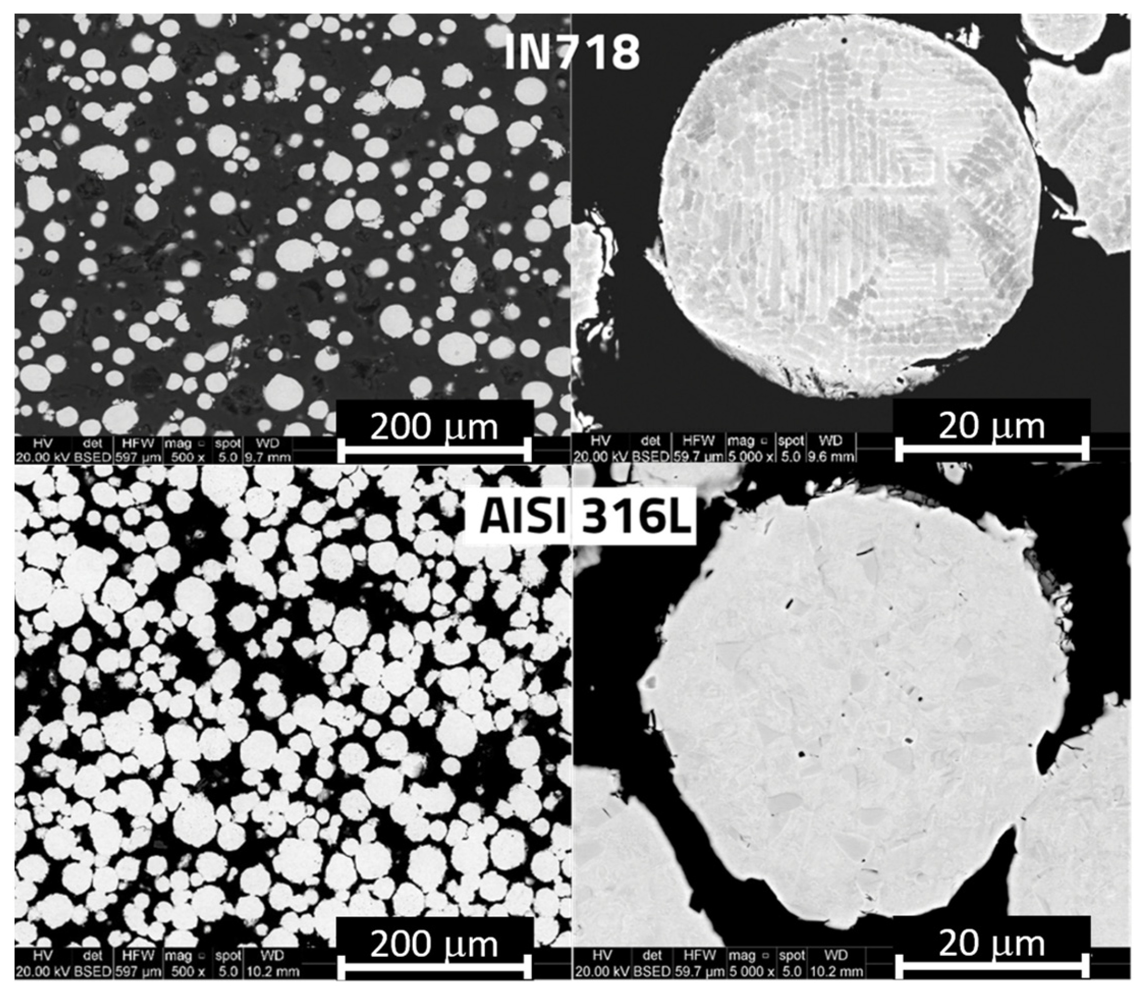
3.1. Filaments Characterization

Figure 4 displays scanning electron microscope (SEM) images at different magnifications of the cross-section of the two filaments utilized in the PDS process. The 316L filament consists of a dispersion of regular-shaped particles, the diameter of which was measured to be 33 ± 8 μm, while the IN718 filaments are filled by spherical particles, the size of which is 26 ± 8 μm. The image clearly shows a significant difference in density between the filaments that could be related to the feedstock material production. However, no information about that came from the producer. In the 3D printing process, the binder plays a principal role so that the shape and size of the metal powder have limited consequences on the early stages of the process. It is possible to observe that the shape of the IN718 is smooth, while the AISI one is more jagged. These aspects become important in debinding and sintering, where size and shape of the particles are relevant in the shape stability of the components and in the diffusion and adhesion mechanisms. Dendritic and equiaxed nano-sized grains characterize the microstructure of IN718 and AISI 316L particles, respectively (Figure 4).

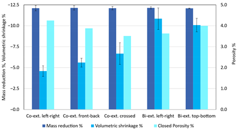
3.2. Density and Geometrical Variations as a Function of Printing Deposition Strategy

Table 4 summarizes the mass, volumetric variations, and closed porosity measured by a picnometer induced by sintering as a function of the printing deposition strategy.
It is observed that there is a higher volumetric shrinkage of bi-extruded samples compared to that of co-extruded ones, which can be attributed to a reciprocal clamping effect of the coupled filaments. As a matter of fact, in co-extruded samples, the IN718 powder is locally surrounded by that of AISI 316L, which, having slightly different densification kinetics (not only due to the different alloy compositions, but at least because of the different mean particle size), gets in the way with the shrinkage of IN718.
No significant variation in the mass reduction was found. In fact, the mass reduction is linked to the loss of PLA during the debinding process, and it remains the same since the polymer fraction is constant in the filaments, and consequently, in the samples. For co-extruded samples, the closed porosity increases as the volumetric shrinkage decreases, with the best result reached by the co-extruded ‘crossed’ sample.
By referring to the Cartesian system shown in Figure 1, Table 5 collects the linear shrinkage along the three directions, x, y, and z. In general, the shrinkage in the x and y direction is higher than that in the building direction (z). For co-extruded cuboids, the highest shrinkage is achieved in the scanning direction (for instance, co-extruded left-right parts experience the highest shrinkage in the x direction, Figure 2). Moreover, co-extruded samples tend to shrink less in all directions compared to bi-extruded samples, in agreement with the results of volumetric shrinkage (Table 4). This could be due to the effect of differential sintering kinetics between the two alloys. While in co-extrusion, the two alloys are mixed together so that the shrinkage of an alloy is constrained by the different shrinkage of the other one (and this promote porosity), in bi-extruded parts, the differential shrinkage kinetics effects are not active in promoting porosity, since each sub-part (say, each alloy) is free to shrink without constriction given by the other alloy. Finally, it is possible to note that the typical voids of the FFF process, which generate ‘tunnels’ parallel to the extrusion direction, influence the shrinkage. Indeed, along these tunnels, due to the large distance among the grains, the sintering mechanisms, such as diffusion, adsorption, and wettability, do not work properly, reducing the approach among the grains. Consequently, in both extrusion modes, the linear shrinkage perpendicular to the deposition direction is lower than in the deposition direction, i.e., the linear shrinkage along the x direction is lower than in the y direction in co-extrusion front-back, bi-extrusion left-right, and bi-extrusion top-bottom, while the opposite happens in co-extruded left-right samples (see nozzle path in Figure 2). In co-extruded crossed samples, the nozzle path changes from the x direction to the y direction at each layer, and consequently, no significant difference in shrinkage between the x and y directions was found.
Figure 5 shows a collection of SEM micrographs at different magnifications of co-extruded (left-right) samples sintered at 1260 °C, with details of the interface between the two alloys in the y–z plane. A lot of porosity is observed, with pore size ranging from 63 μm to 338 μm. Large pores (tunnels) are an intrinsic characteristic of the deposition process in FFF [36,46,47,48]. Before the sintering process, these defects are related to adhesion mechanisms and material properties such as diffusion, adsorption, and wettability [49], and they can be reduced tuning process parameters [50,51,52]. After the sintering process, pores remain due to, above all, a non-optimized sintering temperature. However, another possible cause could be attributed to different densification kinetics of the two alloys, as mentioned above. In fact, in such a condition, it is very likely that the densification shrinkage of an alloy is prevented by a different grade of shrinkage of the other one.
Even though the total porosity detected with the 3D scanner is high and similar for all samples (around 54%), making it unsuitable for functional components, and despite both IN718 and AISI 316L particles being decorated by a secondary phase, Figure 5 shows a good bond at the interface between the two alloys. An EDS line scan was carried out across the IN718 and AISI 316L interface to better investigate the interdiffusion of elements and secondary phases.
At the sintering temperatures, the solubility of Ni in Fe (and vice versa) is unlimited [53]. This allows Ni to diffuse toward 316L and Fe toward IN718, both in the austenitic phase, giving rise to the gradients highlighted with dot straight lines in Figure 6. Across the interface, and inside the 316L particles, a darker phase is present that is characterized by higher concentrations of Cr and C (Figure 6). It was therefore identified as Cr carbide. Despite the low amount of carbon, the chance to find carbides in the microstructure did not seem to be a novelty in literature, as described by the work of Yin et al. [54], who found that in additively manufactured 316L SS, discontinuous coarse M23C6 carbide precipitated along high-angle grain boundaries (HAGBs) after short-time thermal exposure (less than 0.5 h) at 800 °C. It is interesting to note that they suggested that, compared to the wrought 316L SS with and without cold work, AM 316L SS exhibits ten times faster nucleation and growth kinetics of all the secondary phases.
Dealing with the PDS process, however, C contamination could derive from the binder ((C3H6O3)x) during the debinding process. Despite the use of Argon to control the furnace atmosphere, carbon residues could remain entrapped inside the pores, diffuse toward to the two alloys, and combine with Cr during cooling to precipitate as carbide. EDS analysis was also carried out inside the particles to detect secondary phases (Figure 7 and Table 6 and Table 7).
The darker phase inside the 316L particle (Figure 7a) was identified as chromium carbide because of the high concentration of Cr and C detected in the corresponding points 1 and 6 (Table 5). Black-colored phases in 316L particles, as those marked with numbers 2 and 5 in Figure 7a, are rich in sulfur and chromium, which suggests the presence of chromium sulfides. Inside IN718 particles, a white-colored secondary phase is clearly visible that was not detected in the original material before processing (point 1, 3 and 5 in Figure 7b). Since this phase is rich in Nb, it is supposed to be the γ″ phase (Ni3Nb) formed during cooling from the sintering temperature.

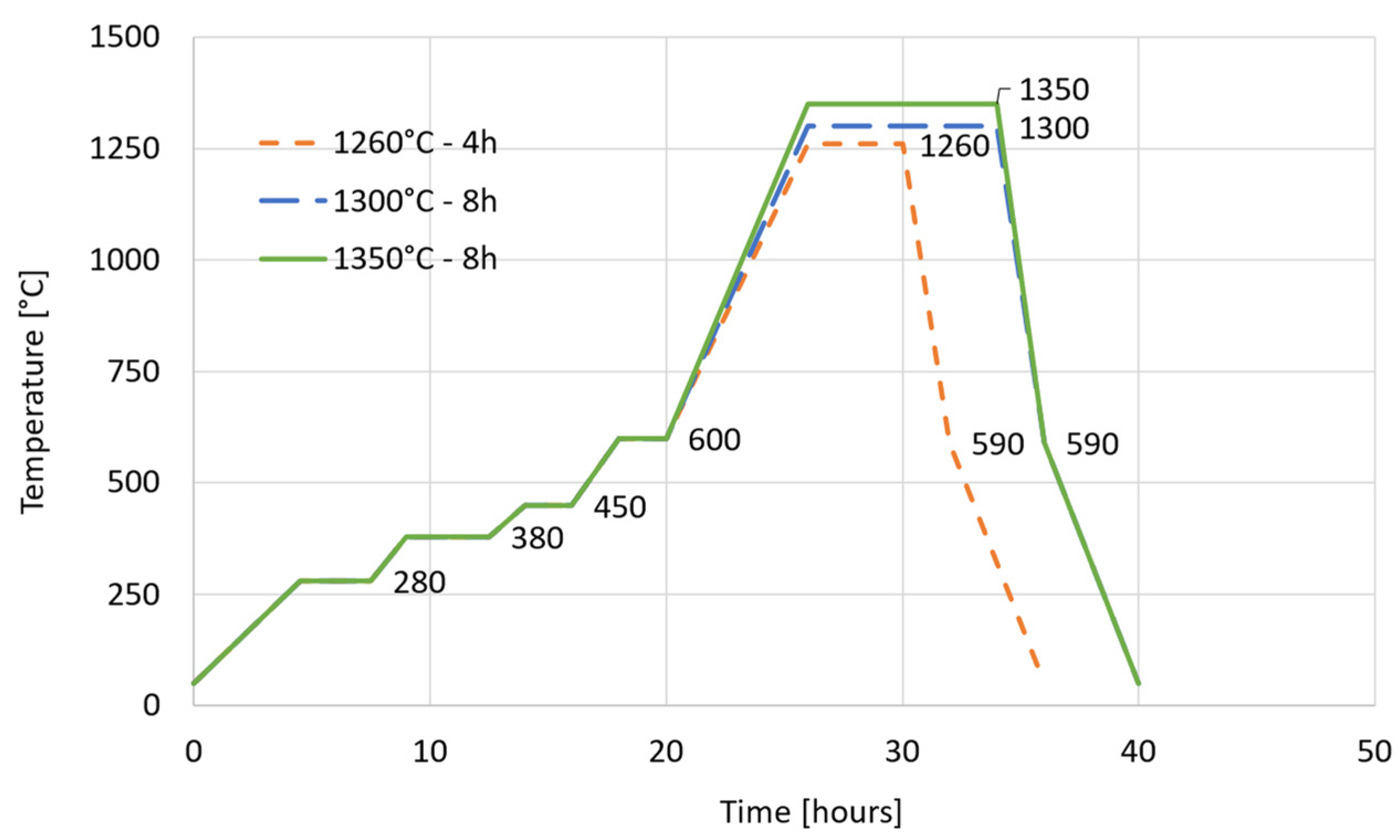
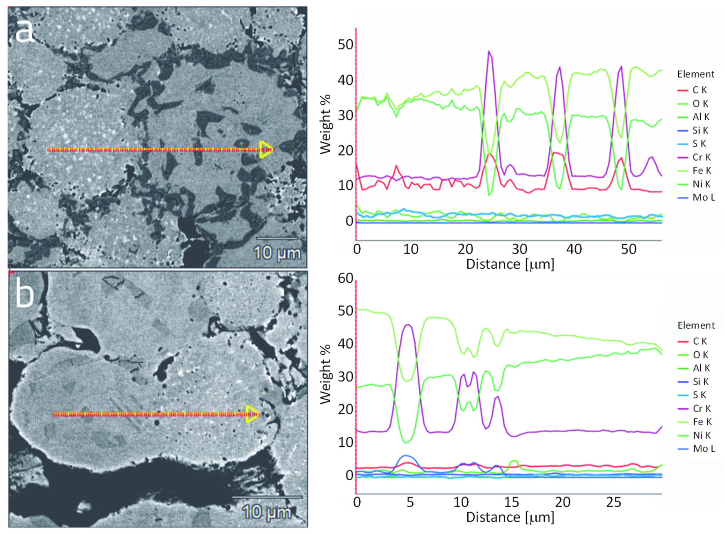
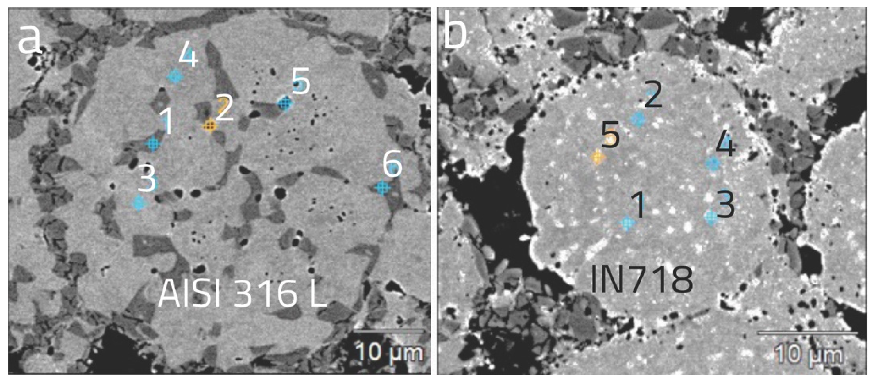
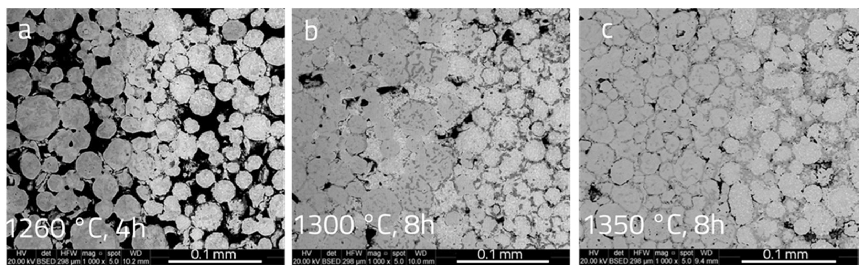
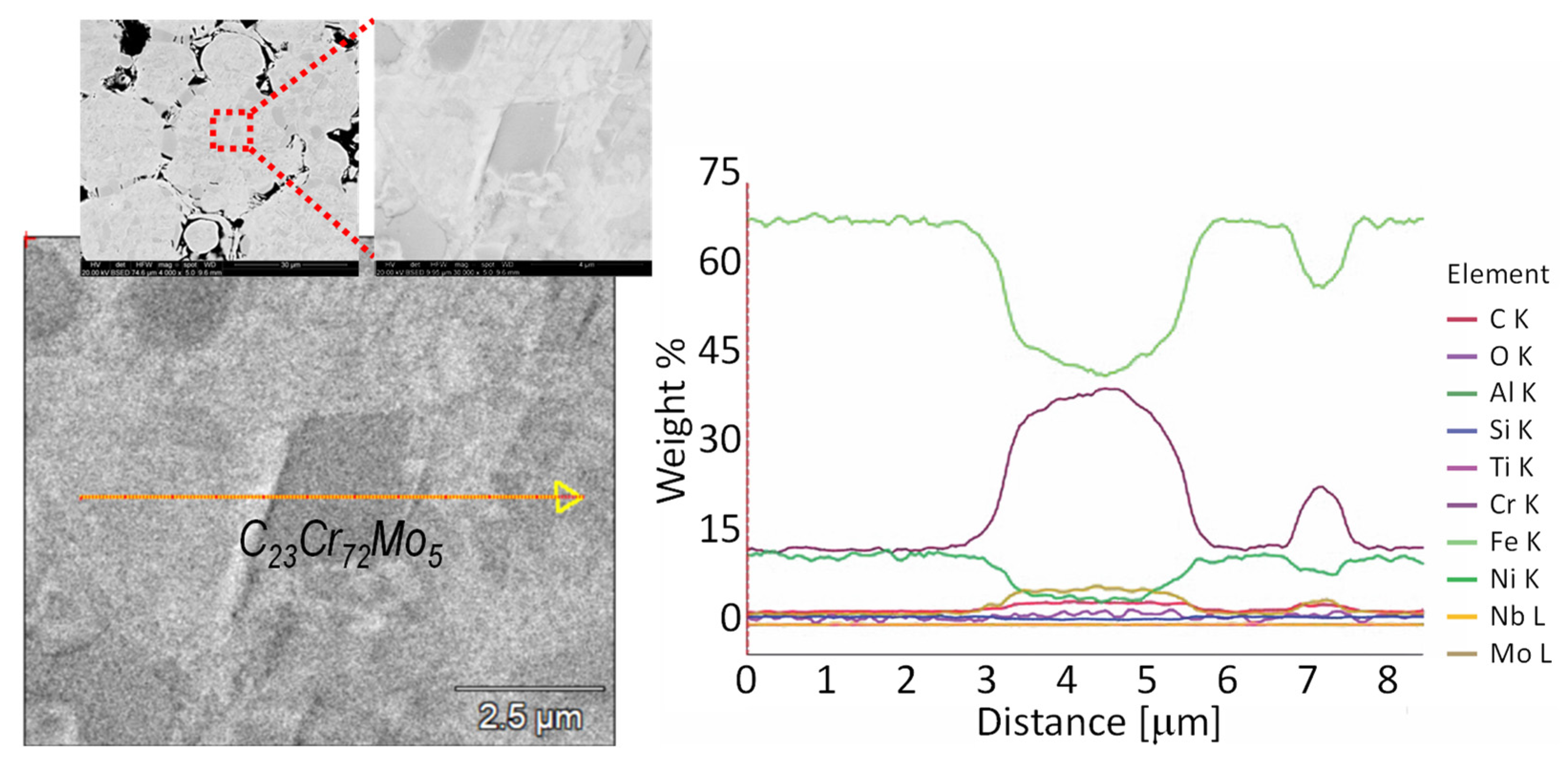
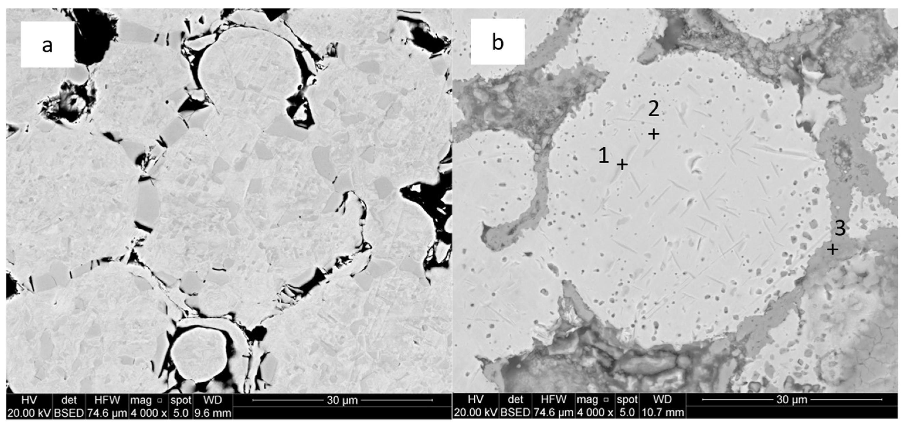
3.3. Effect of Higher Sintering Temperatures and Longer Holding Time

Because of the poor material densification obtained in most of the samples treated at 1260 °C, it was decided to increase both the sintering holding time, from 4 h to 8 h, and the sintering temperatures, from 1260 °C to 1300 °C to 1350 °C. The results are shown in Figure 8, where it is clearly visible that the densification increased as the temperature, as well as the holding time, increased.
By calculating the porosity through image analysis, it was found a value of 42.4% ± 4.9%, 9.6% ± 3.1% and 3.8% ± 0.7% for samples sintered at 1260 °C, 1300 °C and 1350 °C, respectively.
The problem of Cr carbide that, by surrounding the powder particle, it inhibits the particle merging, remains. A detailed investigation was carried out on the bi-extruded sampled sintered at 1300 °C (8 h). Both AISI 316L and IN718 showed Cr-rich phases (Figure 9).
EDS line scans across the Cr-rich phases are shown in Figure 10 and Figure 11. Using the database of the EDS software and the EDS analysis results, a tentative attempt to identify the Cr carbides was carried out as reported in previous figures (Figure 10 and Figure 11). It is worth mentioning that Wang et al., (2022) predicted Cr aggregation zones at particle surfaces and grain boundaries of sintered AISI 316L using molecular dynamic simulation. It is supposed that in the present work, precipitation of carbides both at particle surfaces and grain boundaries (GB) of AISI 316L are due to a combination of such segregation phenomenon with the fast carbon surface and GB diffusion (Yin et al., 2021). To go inside the Cr-carbides issue, it was decided to carry out a solubilization heat treatment at 1050 °C (3 h holding time) followed by water quenching. Despite the oxidation of particle boundaries due to the non-controlled laboratory oven atmosphere, where the heat treatment was carried out, Cr-carbides dissolved, as expected (Figure 12).
Results of EDS analysis on points 1, 2, and 3, shown in Figure 12b, are collected in Table 8. After solution heat treatment, particles are decorated by Cr-oxide, while, inside the particles, Cr-nitrides in the form of rods were detected, due to the nitrogen oversaturation followed by precipitation during quenching.
These new insights should be integrated into the frameworks of design for AM and multi-material AM [35,55,56,57], including the multi-material models that are essential tools for the part of geometry and material distribution design. As mentioned, the PDS of metals is an eco-friendly AM process due to the low energy consumption and low waste material [18]. More broadly, environmental implications of metal AM, oriented to functionally graded materials in a circular design perspective, were previously discussed [58,59,60] and could be integrated in a comprehensive design methodology that considers the PDS process, the functional requirements, and the sustainable development.

4. Conclusions

Co-extruded and bi-extruded IN718-AISI 316L bi-metallic parts were produced for the first time by 3D printing, debinding, and sintering. In 3D printing, five material layouts, obtained adopting different nozzle configurations and paths, were studied. A thermal debinding followed by sintering at different temperatures, and holding times were investigated in terms of microstructure, dimensional stability, and relative density.
In all the specimens, a good bond at the interface between the two alloys was observed. In the deposition direction, it is possible to see higher shrinkage, while in the other direction, the shrinkage is lower due to the typical void of the FFF process, which reduces the effectiveness of the sintering process. ‘Crossed’ co-extruded parts showed the best geometrical stability and the highest shrinkage compared to all the other co-extruded samples. Even lower porosity values (3.8% ± 0.7%) can be obtained by increasing both the temperature (up to 1350 °C) and holding time (up to 8 h) of the sintering heat treatment. At the sintering temperatures, the solubility of Ni in Fe allows Ni to diffuse toward 316L and Fe toward IN718, both in the austenitic phase. In all the trials, chromium carbides were detected at the powder particle boundaries of the two alloys and at the grain boundaries of AISI 316L SS. They were attributed to carbon contamination coming from the binder.
PDS is a demonstrated cost-effective metal AM technology that enables the production of complex shapes with low energy consumption, thus contributing to sustainability. Despite the efforts of this research, there are still many open issues in metal multi-material PDS processes to be explored, such as process optimization, other material properties characterization, and the development of design strategies integrating the sustainable principle.

Author Contributions

Conceptualization, G.S.; methodology, P.F. and G.S.; software, G.S.; validation, P.F. and G.S.; formal analysis P.F., A.F. and G.S.; investigation, P.F., A.F., H.E. and G.S.; resources, P.F., H.E. and G.S.; data curation, P.F., A.F. and G.S.; writing—original draft preparation, P.F.; writing—review and editing, P.F., A.F., H.E. and G.S.; visualization, P.F., A.F. and G.S.; supervision, P.F. and G.S.; project administration, P.F. and G.S.; funding acquisition, P.F. and G.S. All authors have read and agreed to the published version of the manuscript.

Funding

This research received no external funding.

Institutional Review Board Statement

Not applicable.

Informed Consent Statement

Not applicable.

Data Availability Statement

The data presented in this study are available on request from the corresponding author.

Conflicts of Interest

The authors declare no conflict of interest.

References

  1. Razavi, S.M.J.; Ferro, P.; Berto, F.; Torgersen, J. Fatigue Strength of Blunt V-Notched Specimens Produced by Selective Laser Melting of Ti-6Al-4V. Theor. Appl. Fract. Mech. 2018, 97, 376–384. [Google Scholar] [CrossRef] [Green Version]
  2. Ferro, P.; Romanin, L.; Berto, F. Understanding Powder Bed Fusion Additive Manufacturing Phenomena via Numerical Simulation. Frat. Integrita Strutt. 2020, 14, 252–284. [Google Scholar] [CrossRef]
  3. Ferro, P.; Meneghello, R.; Savio, G.; Berto, F. A Modified Volumetric Energy Density–Based Approach for Porosity Assessment in Additive Manufacturing Process Design. Int. J. Adv. Manuf. Technol. 2020, 110, 1911–1921. [Google Scholar] [CrossRef]
  4. Bobbio, L.D.; Qin, S.; Dunbar, A.; Michaleris, P.; Beese, A.M. Characterization of the Strength of Support Structures Used in Powder Bed Fusion Additive Manufacturing of Ti-6Al-4V. Addit. Manuf. 2017, 14, 60–68. [Google Scholar] [CrossRef]
  5. Tan, H.; Fan, W.; Qian, Y.; Chen, Y.; Liu, S.; Lin, X. Influence of Inclined Substrate on Process Characteristics of Directed Energy Deposition. Opt. Laser Technol. 2020, 129, 106288. [Google Scholar] [CrossRef]
  6. Roberts, J.W.; Sutcliffe, C.J.; Green, P.L.; Black, K. Modelling of Metallic Particle Binders for Increased Part Density in Binder Jet Printed Components. Addit. Manuf. 2020, 34, 101244. [Google Scholar] [CrossRef]
  7. Bournias-Varotsis, A.; Han, X.; Harris, R.A.; Engstrøm, D.S. Ultrasonic Additive Manufacturing Using Feedstock with Build-in Circuitry for 3D Metal Embedded Electronics. Addit. Manuf. 2019, 29, 100799. [Google Scholar] [CrossRef]
  8. Liu, M.; Yi, H.; Cao, H.; Huang, R.; Jia, L. Heat Accumulation Effect in Metal Droplet-Based 3D Printing: Evolution Mechanism and Elimination Strategy. Addit. Manuf. 2021, 48, 102413. [Google Scholar] [CrossRef]
  9. Agarwala, M.K.; Weeren, R.V.; Bandyopadhyay, A.; Safari, A.; Danforth, S.C.; Priedeman, W.R. Filament Feed Materials for Fused Deposition Processing of Ceramics and Metals. Proc. Solid Free. Fabr. Symp. 1996, 451–458. Available online: http://hdl.handle.net/2152/70277 (accessed on 24 July 2023).
  10. Gonzalez-Gutierrez, J.; Cano, S.; Schuschnigg, S.; Kukla, C.; Sapkota, J.; Holzer, C. Additive Manufacturing of Metallic and Ceramic Components by the Material Extrusion of Highly-Filled Polymers: A Review and Future Perspectives. Materials 2018, 11, 840. [Google Scholar] [CrossRef] [Green Version]
  11. Watson, A.; Belding, J.; Ellis, B.D. Characterization of 17-4 PH Processed via Bound Metal Deposition (BMD). In TMS 2020 149th Annual Meeting & Exhibition Supplemental Proceedings; The Minerals, Metals & Materials Series; Springer: Cham, Switzerland, 2020; pp. 205–216. [Google Scholar] [CrossRef]
  12. Liu, B.; Wang, Y.; Lin, Z.; Zhang, T. Creating Metal Parts by Fused Deposition Modeling and Sintering. Mater. Lett. 2020, 263, 127252. [Google Scholar] [CrossRef]
  13. Galati, M.; Minetola, P. Analysis of Density, Roughness, and Accuracy of the Atomic Diffusion Additive Manufacturing (ADAM) Process for Metal Parts. Materials 2019, 12, 4122. [Google Scholar] [CrossRef] [Green Version]
  14. Wang, F.; You, S.; Jiang, D.; Ning, F. Study on Sintering Mechanism for Extrusion-Based Additive Manufacturing of Stainless Steel through Molecular Dynamics Simulation. Addit. Manuf. 2022, 58, 102991. [Google Scholar] [CrossRef]
  15. Balubaid, M.; Alsaadi, N. Achieving Sustainability in Manufacturing through Additive Manufacturing: An Analysis of Its Enablers. Sustainability 2023, 15, 9504. [Google Scholar] [CrossRef]
  16. Liu, W.; Liu, X.; Liu, Y.; Wang, J.; Evans, S.; Yang, M. Unpacking Additive Manufacturing Challenges and Opportunities in Moving towards Sustainability: An Exploratory Study. Sustainability 2023, 15, 3827. [Google Scholar] [CrossRef]
  17. Peng, T.; Kellens, K.; Tang, R.; Chen, C.; Chen, G. Sustainability of Additive Manufacturing: An Overview on Its Energy Demand and Environmental Impact. Addit. Manuf. 2018, 21, 694–704. [Google Scholar] [CrossRef]
  18. Nadagouda, M.N.; Ginn, M.; Rastogi, V. A Review of 3D Printing Techniques for Environmental Applications. Curr. Opin. Chem. Eng. 2020, 28, 173–178. [Google Scholar] [CrossRef]
  19. Lieberwirth, C.; Harder, A.; Seitz, H. Extrusion Based Additive Manufacturing of Metal Parts. J. Mech. Eng. Autom. 2017, 7, 79–83. [Google Scholar] [CrossRef] [Green Version]
  20. Gao, C.; Wolff, S.; Wang, S. Eco-Friendly Additive Manufacturing of Metals: Energy Efficiency and Life Cycle Analysis. J. Manuf. Syst. 2021, 60, 459–472. [Google Scholar] [CrossRef]
  21. Barone, S.; Cucinotta, F.; Sfravara, F. A Comparative Life Cycle Assessment of Utility Poles Manufactured with Different Materials and Dimensions. In Advances on Mechanics, Design Engineering and Manufacturing; Lecture Notes in Mechanical Engineering; Springer: Cham, Switzerland, 2017; pp. 91–99. [Google Scholar] [CrossRef]
  22. Cucinotta, F.; Raffaele, M.; Salmeri, F. A Topology Optimization of a Motorsport Safety Device. In Design Tools and Methods in Industrial Engineering; ADM 2019; Lecture Notes in Mechanical Engineering; Springer International Publishing: Berlin/Heidelberg, Germany, 2020; pp. 400–409. [Google Scholar] [CrossRef]
  23. Cucinotta, F.; Raffaele, M.; Salmeri, F. A Stress-Based Topology Optimization Method by a Voronoi Tessellation Additive Manufacturing Oriented. Int. J. Adv. Manuf. Technol. 2019, 103, 1965–1975. [Google Scholar] [CrossRef]
  24. Gisario, A.; Kazarian, M.; Martina, F.; Mehrpouya, M. Metal Additive Manufacturing in the Commercial Aviation Industry: A Review. J. Manuf. Syst. 2019, 53, 124–149. [Google Scholar] [CrossRef]
  25. Zhang, W.; Xu, J. Materials & Design Advanced Lightweight Materials for Automobiles: A Review. Mater. Des. 2022, 221, 110994. [Google Scholar] [CrossRef]
  26. Ramazani, H.; Kami, A. Metal FDM, a New Extrusion-Based Additive Manufacturing Technology for Manufacturing of Metallic Parts: A Review. Prog. Addit. Manuf. 2022, 7, 609–626. [Google Scholar] [CrossRef]
  27. Thompson, Y.; Gonzalez-Gutierrez, J.; Kukla, C.; Felfer, P. Fused Filament Fabrication, Debinding and Sintering as a Low Cost Additive Manufacturing Method of 316L Stainless Steel. Addit. Manuf. 2019, 30, 100861. [Google Scholar] [CrossRef]
  28. Thompson, Y.; Zissel, K.; Förner, A.; Gonzalez-Gutierrez, J.; Kukla, C.; Neumeier, S.; Felfer, P. Metal Fused Filament Fabrication of the Nickel-Base Superalloy IN 718. J. Mater. Sci. 2022, 57, 9541–9555. [Google Scholar] [CrossRef]
  29. Klöden, B.; Weissgärber, T.; Kieback, B.; Lange, I. The Processing and Properties of Metal Injection Moulded Superalloys. Powder Inject. Mould. Int. 2013, 7, 53–66. [Google Scholar]
  30. Ferro, P.; Fabrizi, A.; Bonollo, F.; Elsayed, H.S.A.; Berto, F.; Savio, G. High Carbon Steel/Inconel 718 Bimetallic Parts Produced via Fused Filament Fabrication and Sintering. Frat. Integrità Strutt. 2023, 17, 246–256. [Google Scholar] [CrossRef]
  31. Ferro, P.; Fabrizi, A.; Elsayed, H.S.A.; Berto, F.; Savio, G. Creating IN718-High Carbon Steel Bi-Metallic Parts by Fused Deposition Modeling and Sintering. Procedia Struct. Integr. 2023, 47, 535–544. [Google Scholar] [CrossRef]
  32. Mousapour, M.; Salmi, M.; Klemettinen, L.; Partanen, J. Feasibility Study of Producing Multi-Metal Parts by Fused Filament Fabrication (FFF) Technique. J. Manuf. Process. 2021, 67, 438–446. [Google Scholar] [CrossRef]
  33. Loh, G.H.; Pei, E.; Harrison, D.; Monzón, M.D. An Overview of Functionally Graded Additive Manufacturing. Addit. Manuf. 2018, 23, 34–44. [Google Scholar] [CrossRef] [Green Version]
  34. Sponchiado, R.; Grigolato, L.; Filippi, S.; Concheri, G.; Meneghello, R.; Savio, G. Heterogeneous Materials Additive Manufacturing: An Overview. In Design Tools and Methods in Industrial Engineering II; ADM 2021; Lecture Notes in Mechanical Engineering; Rizzi, C., Campana, F., Bici, M., Gherardini, F., Ingrassia, T., Cicconi, P., Eds.; Springer: Cham, Switzerland, 2022; pp. 462–473. ISBN 9783030912345. [Google Scholar]
  35. Leoni, F.; Dal Fabbro, P.; Rosso, S.; Grigolato, L.; Meneghello, R.; Concheri, G.; Savio, G. Functionally Graded Additive Manufacturing: Bridging the Gap between Design and Material Extrusion. Appl. Sci. 2023, 13, 1467. [Google Scholar] [CrossRef]
  36. Sponchiado, R.; Rosso, S.; Dal Fabbro, P.; Grigolato, L.; Elsayed, H.; Bernardo, E.; Maltauro, M.; Uccheddu, F.; Meneghello, R.; Concheri, G.; et al. Modeling Materials Coextrusion in Polymers Additive Manufacturing. Materials 2023, 16, 820. [Google Scholar] [CrossRef]
  37. Dugauguez, O.; Torralba, J.M.; Barrière, T.; Gelin, J.C. Unconventional Methods of Sintering Inconel 718 MIM Samples. Key Eng. Mater. 2016, 716, 830–839. [Google Scholar] [CrossRef]
  38. Johari, N.; Ibrahim, R.; Ahmad, M.A.; Suleiman Ahmad, M.J.; Talib, A.R.A. The Effect of Sintering Temperature on Physical Properties of Sintered Inconel 718 for Potential Aerospace Industry Application. Adv. Mater. Res. 2014, 879, 139–143. [Google Scholar] [CrossRef]
  39. Youhua, H.; Yimin, L.; Hao, H.; Jia, L.; Xiao, T. Preparation and Mechanical Properties of Inconel718 Alloy by Metal Injection Molding. Rare Met. Mater. Eng. 2010, 39, 775–780. [Google Scholar] [CrossRef]
  40. Levasseur, D.; Brochu, M. Supersolidus Liquid Phase Sintering Modeling of Inconel 718 Superalloy. Metall. Mater. Trans. A Phys. Metall. Mater. Sci. 2016, 47, 869–876. [Google Scholar] [CrossRef]
  41. Dugauguez, O.; Torralba, J.M.; Barriere, T.; Gelin, J.-C. Field Assisted Hot Pressing of Sintering Inconel 718 MIM Samples. In Proceedings of the 19th International ESAFORM Conference on Material Forming, Nantes, France, 27–29 April 2016; Volume 716, p. 050003. [Google Scholar] [CrossRef]
  42. Özgün, Ö.; Gulsoy, H.O.; Yilmaz, R.; Findik, F. Microstructural and Mechanical Characterization of Injection Molded 718 Superalloy Powders. J. Alloys Compd. 2013, 576, 140–153. [Google Scholar] [CrossRef]
  43. Damon, J.; Dietrich, S.; Gorantla, S.; Popp, U.; Okolo, B.; Schulze, V. Process Porosity and Mechanical Performance of Fused Filament Fabricated 316L Stainless Steel. Rapid Prototyp. J. 2019, 25, 1319–1327. [Google Scholar] [CrossRef]
  44. Kachit, M.; Kopp, A.; Adrien, J.; Maire, E.; Boulnat, X. Direct-Ink Writing and Compression Behavior by in Situ Micro-Tomography of Architectured 316L Scaffolds with a Two-Scale Porosity. J. Mater. Res. Technol. 2022, 20, 1341–1351. [Google Scholar] [CrossRef]
  45. Contreras, J.L.; Fuentes, A.G. Sintering of Supported Metal Catalysts. In Sintering—Methods and Products; InTech: Houston, TX, USA, 2012. [Google Scholar]
  46. Radzuan, N.A.M.; Sulong, A.B.; Verma, A.; Muhamad, N. Layup Sequence and Interfacial Bonding of Additively Manufactured Polymeric Composite: A Brief Review. Nanotechnol. Rev. 2021, 10, 1853–1872. [Google Scholar] [CrossRef]
  47. Turner, B.N.; Strong, R.; Gold, S.A. A Review of Melt Extrusion Additive Manufacturing Processes: I. Process Design and Modeling. Rapid Prototyp. J. 2014, 20, 192–204. [Google Scholar] [CrossRef]
  48. Papon, E.A.; Haque, A. Tensile Properties, Void Contents, Dispersion and Fracture Behaviour of 3D Printed Carbon Nanofiber Reinforced Composites. J. Reinf. Plast. Compos. 2018, 37, 381–395. [Google Scholar] [CrossRef]
  49. Freund, R.; Watschke, H.; Heubach, J.; Vietor, T. Determination of Influencing Factors on Interface Strength of Additively Manufactured Multi-Material Parts by Material Extrusion. Appl. Sci. 2019, 9, 1782. [Google Scholar] [CrossRef] [Green Version]
  50. Gonabadi, H.; Chen, Y.; Yadav, A.; Bull, S. Investigation of the Effect of Raster Angle, Build Orientation, and Infill Density on the Elastic Response of 3D Printed Parts Using Finite Element Microstructural Modeling and Homogenization Techniques. Int. J. Adv. Manuf. Technol. 2022, 118, 1485–1510. [Google Scholar] [CrossRef]
  51. Tamburrino, F.; Graziosi, S.; Bordegoni, M. The Influence of Slicing Parameters on the Multi-Material Adhesion Mechanisms of FDM Printed Parts: An Exploratory Study. Virtual Phys. Prototyp. 2019, 14, 316–332. [Google Scholar] [CrossRef]
  52. Dal Fabbro, P.; La Gala, A.; Van De Steene, W.; D’hooge, D.R.; Lucchetta, G.; Cardon, L.; Fiorio, R. Influence of Machine Type and Consecutive Closed-Loop Recycling on Macroscopic Properties for Fused Filament Fabrication of Acrylonitrile-Butadiene-Styrene Parts. Rapid Prototyp. J. 2021, 27, 268–277. [Google Scholar] [CrossRef]
  53. Swartzendruber, L.J.; Itkin, V.P.; Alcock, C.B. The Fe-Ni (Iron-Nickel) System. J. Phase Equilibria 1991, 12, 288–312. [Google Scholar] [CrossRef]
  54. Yin, H.; Song, M.; Deng, P.; Li, L.; Prorok, B.C.; Lou, X. Thermal Stability and Microstructural Evolution of Additively Manufactured 316L Stainless Steel by Laser Powder Bed Fusion at 500–800 °C. Addit. Manuf. 2021, 41, 101981. [Google Scholar] [CrossRef]
  55. Rosso, S.; Uriati, F.; Grigolato, L.; Meneghello, R.; Concheri, G.; Savio, G. An Optimization Workflow in Design for Additive Manufacturing. Appl. Sci. 2021, 11, 2572. [Google Scholar] [CrossRef]
  56. Yao, X.; Moon, S.K.; Bi, G.; Wei, J. A Multi-Material Part Design Framework in Additive Manufacturing. Int. J. Adv. Manuf. Technol. 2018, 99, 2111–2119. [Google Scholar] [CrossRef]
  57. Garcia, D.; Wu, Z.; Kim, J.Y.; Yu, H.Z.; Zhu, Y. Heterogeneous Materials Design in Additive Manufacturing: Model Calibration and Uncertainty-Guided Model Selection. Addit. Manuf. 2019, 27, 61–71. [Google Scholar] [CrossRef]
  58. Arrizubieta, J.I.; Ukar, O.; Ostolaza, M.; Mugica, A. Study of the Environmental Implications of Using Metal Powder in Additive Manufacturing and Its Handling. Metals 2020, 10, 261. [Google Scholar] [CrossRef] [Green Version]
  59. El-Galy, I.M.; Saleh, B.I.; Ahmed, M.H. Functionally Graded Materials Classifications and Development Trends from Industrial Point of View. SN Appl. Sci. 2019, 1, 1378. [Google Scholar] [CrossRef] [Green Version]
  60. Singh, R.; Kumar, R.; Farina, I.; Colangelo, F.; Feo, L.; Fraternali, F. Multi-Material Additive Manufacturing of Sustainable Innovative Materials and Structures. Polymers 2019, 11, 62. [Google Scholar] [CrossRef] [Green Version]
Figure 1. Samples and equipment. Photos of a co-extruded cuboids sample in a left-right configuration: (a) before sintering and (b) after sintering, based on the reference frame depicted in the image of the 3D printer (c). Cyclops hotend, represented in section (d), shows the material flow in the hotend that is adopted for “Co-extruded” samples. Chimera hotend (e) adopted for the “Bi-extruded” samples. Image of the tubular furnace (f) adopted for the sintering process (Zetasinter by Zetamix).
Sustainability 15 11911 g001
Figure 2. The material layout resulting from nozzle path can be observed in two scenarios: (a) when the nozzle moves along the x-axis, and (b) when the nozzle moves along the y-axis. The nozzle path in the first two layers, resulting samples, and magnification of material distribution in the studied configurations: (c) left-right co-extrusion, (d) front-back co-extrusion, (e) crossed co-extrusion, (f) left-right bi-extrusion, and (g) top-bottom bi-extrusion. All the paths provide an initial skirt, which helps prime the nozzle and establish a smooth flow of filament.
Sustainability 15 11911 g002
Figure 3. Heat treatment recipes for thermal debinding, pre-sintering, and sintering.
Sustainability 15 11911 g003
Figure 4. SEM images at different magnifications of the cross-section of IN718 and AISI 316L filaments.
Sustainability 15 11911 g004
Figure 5. SEM micrographs at different magnifications of the sintered co-extruded (left-right) samples with details of the interface between the two alloys (sintering temperature, 1260 °C).
Sustainability 15 11911 g005
Figure 6. EDS line scan across the IN718 and AISI 316L interface of co-extruded (left-right) (a) and bi-extruded (b) samples sintered at 1260 °C (4 h).
Sustainability 15 11911 g006
Figure 7. SEM micrographs with indication of points where EDS analysis was carried out (see results in Table 6 and Table 7): AISI 316L (a); IN718 (b).
Sustainability 15 11911 g007
Figure 8. SEM micrographs of the AISI 316L/IN718 interface of bi-extruded (left–right) PDS parts at different sintering heat treatments: 1260 °C, 4 h (a); 1300 °C, 8 h (b); and 1350 °C, 8 h (c).
Sustainability 15 11911 g008
Figure 9. SEM micrographs at different magnifications of the bi-extruded sample sintered at 1300 °C for 8 h.
Sustainability 15 11911 g009
Figure 10. SEM micrographs and EDS line scan across a Cr-rich phase inside the AISI 316 particle sintered at 1300 °C, 8 h.
Sustainability 15 11911 g010
Figure 11. SEM micrographs and EDS line scan across a Cr-rich phase at particles boundary of AISI 316 and IN718, sintered at 1300 °C, 8 h.
Sustainability 15 11911 g011
Figure 12. Sintered (1300 °C, 8 h) AISI 316L: (a) before solution heat treatment, and (b) after solution heat treatment.
Sustainability 15 11911 g012
Table 2. Chemical composition of the two alloys (wt%), as declared by the filaments producer, The Virtual Foundry, LLC, Sthoughton, WI, USA.
MaterialNiCrNbMoAlCTi
IN71845–605–18<3<3<1<1<1
AISI 316L10–1316.5–18.50.0082–2.50.5Max. 0.110.43
Table 3. Fused filament fabrication process parameters.
Layer Height (mm)Printing Speed (mm/s)Nozzle Temperature (°C)Bed Temperature (°C)Extrusion Width (mm)Nozzle Diameter (mm)
0.4152105010.8
Table 4. Mass and volumetric variations and closed porosity induced by sintering at 1260 °C.
Sample Mass Variation (%) 1 Volumetric Shrinkage (%) 2Closed Porosity (%) 3
Co-extruded left-right−12.10 ± 0.32−4.59 ± 0.644.25
Co-extruded front-back−12.13 ± 0.26−5.60 ± 0.523.88
Co-extruded crossed−12.10 ± 0.21−6.68 ± 1.293.51
Bi-extruded left-right−12.13 ± 0.13−10.84 ± 1.293.63
Bi-extruded top-bottom−12.07 ± 0.04−10.08 ± 0.814.00
Sustainability 15 11911 i001
1  m a f t e r   s i n t e r i n g m b e f o r e   s i n t e r i n g m b e f o r e   s i n t e r i n g , 2  V a f t e r   s i n t e r i n g V b e f o r e   s i n t e r i n g V b e f o r e   s i n t e r i n g   ,    3  1 p i c n o m e t e r   d e n s i t y m a t e r i a l   d e n s i t y .
Table 5. Linear shrinkage induced by sintering (at 1260 °C) as a function of deposition strategy (x, y, and z refer to the reference system in Figure 1).
Sample Linear Shrinkage,
x Component (%)
Linear Shrinkage,
y Component (%)
Linear Shrinkage,
z Component (%)
Co-extruded left-right−1.67 ± 0.32−1.32 ± 0.51−0.78 ± 0.09
Co-extruded front-back−1.36 ± 0.70−1.60 ± 0.24−0.76 ± 0.10
Co-extruded crossed−2.89 ± 0.60−2.78 ± 0.81−0.74 ± 0.10
Bi-extruded left-right−2.42 ± 0.60−4.89 ± 0.56−2.74 ± 0.98
Bi-extruded top-bottom−3.88 ± 0.16−4.07 ± 0.4−2.67 ± 0.11
Table 6. EDS analysis of the AISI 316L particle shown in Figure 7a.
CAlSiSTiCrMnFeNiMo
15.550.150.18--51.46-31.196.84.69
22.310.110.2610.140.2720.056.4845.4414.94-
31.760.130.42--14.35-58.4421.403.50
41.78-0.43--13.87-62.3119.232.38
52.780.120.1616.45-25.4913.7930.8510.35-
65.010.140.18--49.34-33.267.504.58
Table 7. EDS analysis of the IN718 particle shown in Figure 7b.
CAlSiTiCrFe NiNbMo
15.570.220.133.949.9216.7424.7833.375.42
22.370.290.550.3315.1526.5948.611.844.27
32.660.180.431.2513.2123.1041.1213.974.08
42.410.250.510.7214.2723.9946.737.144.00
52.340.260.292.2612.5722.5137.7417.344.68
Table 8. EDS analysis of the AISI 316L particle shown in Figure 12b.
CNOAlSiSCrMnFeNiMo
12.103.644.350.090.37-40.88039.126.234.17
21.83-4.36-0.74-16.60-63.6110.702.46
31.05-24.710.112.20-46.41-21.862.880.78
Disclaimer/Publisher’s Note: The statements, opinions and data contained in all publications are solely those of the individual author(s) and contributor(s) and not of MDPI and/or the editor(s). MDPI and/or the editor(s) disclaim responsibility for any injury to people or property resulting from any ideas, methods, instructions or products referred to in the content.

