Article

Hybrid Particle Swarm and Gravitational Search Algorithm-Based Optimal Fractional Order PID Control Scheme for Performance Enhancement of Offshore Wind Farms

1
Electrical Power and Machines Department, Faculty of Engineering, Ain Shams University, Cairo 11517, Egypt
2
Faculty of Engineering and Technology, Future University in Egypt, Cairo 11835, Egypt
3
Electrical Engineering Department, College of Engineering, King Saud University, Riyadh 11421, Saudi Arabia
4
Department of Electrical Engineering, University of Jaén, 23700 Linares, Spain
*
Author to whom correspondence should be addressed.
Sustainability 2023, 15(15), 11912; https://doi.org/10.3390/su151511912
Submission received: 16 July 2023 / Revised: 22 July 2023 / Accepted: 31 July 2023 / Published: 2 August 2023

Abstract

:
This article aimed to introduce a novel application of a hybrid particle swarm optimizer and gravitational search algorithm (HPSOGSA) that can be used for optimal control of offshore wind farms’ voltage source converter connected to HVDC transmission lines. Specifically, the algorithm was used to design fractional-order proportional-integral-derivative (FOPID) controller parameters designed to minimize the system’s objective function based on an integral squared error. The proposed FOPID controller was applied to improve offshore wind farm performance under different transient conditions, and its results were compared with a PI controller that was designed using a genetic algorithm and grey wolf optimization algorithm. The fault ride-through capabilities of the proposed control strategy were also evaluated. The findings suggest that the HPSOGSA-based FOPID controller outperformed the other two methods, significantly enhancing offshore wind farm operations. The control strategy was thoroughly tested using MATLAB/Simulink under various operating scenarios.

1. Introduction

Due to several natural and manufactured variables, including greenhouse gas emissions, deforestation, and changes in land use, the world climate is undergoing substantial changes. Increasing temperatures, increasing sea levels, and an increase in the frequency of extreme weather occurrences are the results of these changes. These changes are having an effect on ecosystems, the security of food and water, and human health all around the world. To minimize emissions and prepare for the current changes, the world is continuously challenged to develop renewable resources like wind and solar energy and integrate them with the electrical grid [1]. Wind energy attains excellent success in minimizing the greenhouse effect. The integration of wind power into the power grid is increasing at a very high rate [2].
An offshore wind farm (OWF) is a group of wind turbines built in a body of water—typically the ocean—to produce electricity from wind energy. They are generally connected to an onshore substation through undersea cables to send the electricity to the grid. Higher wind speeds and fewer disturbances at offshore wind farms than onshore wind farms contribute to more reliable energy production. They could also produce a lot of electricity, which would compensate for the need for fossil fuels and lower greenhouse gas emissions. The utilization of OWF as a renewable energy source is rapidly increasing.

1.1. Literature Review

HVDC transmission is the best method to transmit electrical power concerning technical and financial perspectives [3,4]. HVDC is more feasible and efficient for power transfer for distances greater than 83 km than HVAC [5,6,7,8]. HVDC efficiency depends on a well-configured converter where it offers a complete control over transmitted power. There are two primary HVDC transmission topologies: VSC-HVDC and LCC-HVDC, to convert AC power to DC power [9,10]. VSC-HVDC uses Insulated Gate Bipolar Transistors (IGBTs) technology, while LCC-HVDC stands for Line Commutated Converter and employs thyristors. The suggested VSC-based HVDC in this paper uses a three-level neutral point clamped converter.
The primary advantage of VSC-HVDC is that it utilizes forced commutation, which eliminates the need for an external source and allows for the control of reactive power independent of active power [11,12]. The LCC exhibits superior power rating and fault tolerance capabilities, while the VSC surpasses power control, flexibility, and converter efficiency.
The most common generators used in offshore wind farms are PMSG and DFIG, where PMSG stands for permanent magnet synchronous generator. PMSG’s excitation is provided through a permanent magnet, which allows it to be used in a wide range of offshore wind farm applications, as it has low weight, compact size, and robustness. PMSG is used in an offshore wind farm [13,14] to improve dynamic behavior and maintain the grid’s constant power. PMSG with a back-to-back converter has become famous for the reasons above, but the most common reason is that PMSG offers maintenance-free operation [15]. DFIG is used as a generator for offshore wind farms [16]. The DFIG rotor can use a partially rated converter with 25–30% of rated power [17], where a new approach to overcome DFIG cons as a flicker phenomenon when connected to weak utility is proposed in [18] where, through regulating the droop coefficient, flicker mitigation is enhanced. MPPT stands for maximum power point tracking and it aims to determine the optimum rotor speed of wind speed corresponding to each instantaneous speed. This technique is to determine the optimum power produced by WECS. Tip speed ratio (TSR) and optimal torque control (OTC) is the most common technique used in MPPT [19,20] where the results demonstrate that the OTC approach achieves smooth output power without requiring additional equipment, as the mechanical component effectively performs power smoothing, while also enabling maximum power extraction from varying wind speeds.
Offshore wind farms use many controllers, but the PI controller is typical because of its robustness and stability. But due to some limitations of PI, as it is susceptible to any change in parameter and non-linear system, various attempts have been made to enhance the performance of PID controllers using fractional calculus, resulting in the development of fractional-order PID (FOPID) controllers. This paper addressed the design and tuning of FOPID controller gains. Unlike conventional PID controllers, FOPID controllers have two extra tuning parameters (λ, μ) [21], which challenge tuning FOPID, where λ is the order of integration and μ is the order of differentiator. FOPID utilizes fractional calculus, which involves the theory of derivatives and integrals with non-integer orders. This approach incorporates short- and long-term memory, with short memory reflecting the distribution of time constants and long-term memory indicating a lack of a specific time scale. FOPID-based power system stabilizer (PSS) designed by bat optimizer proved to have superiority over PID-based PSS designed by firefly optimizer. All simulation results were verified in [22] using different objective functions, like integral absolute error (IAE), integral square error (ISE), integral time absolute error (ITAE), and integral time squared error (ITSE). The bat algorithm has been demonstrated as an efficient approach for optimally designing a fractional order PID-PSS stabilizer, showcasing its ability to yield rapid time domain response and effectively dampen oscillations [22].
The MPPT technique uses the proposed controller to extract the maximum power from wind turbines [23]. Optimal fractional order PID is introduced in [24] and designed through an ant lion optimizer, and simulations are verified using different objective functions such as IAE, ISE, ITAE, and ITSE. In [25], a detailed comparison was held between six different optimization techniques to tune adaptive PI controller (API), and the harmony search hybrid equilibrium algorithm proved its efficiency over other algorithms.
A fuzzy logic controller (FLC) can handle system non-linearity based on if-then rules. FLC has a simple design requirement, is less sensitive to changes in controller parameter, and does not depend on the mathematical model, but it is challenging to design membership function. In [26], a comparison was made to tune the PID controller, the FLC exhibited superior tracking of the reference control condition and demonstrated improved robustness when system parameters were altered.
The cascaded adaptive neuro-fuzzy controller was proposed to control IGBTs-based frequency converter to enhance the stability of DFIG-based wind farms. A novel design of a fuzzy PID controller and its integration with classical PID was presented [27]. The fuzzy logic control strategy was presented in [28] as a control strategy for performance improvement of grid-connected PMSG driven by variable speed wind turbine connected via VSC connected back-to-back through dc-link-tuned online using continuously mixed p-norm (CMPN). The deep neural learning approach was investigated in [29], which was based on long short-term memory units and convolutional neural networks (CNN) to implement predictive control in offshore wind farms. An artificial neural network (ANN) was used to adapt PI controller constants online to overcome the disadvantages of the PI controller. A new control strategy adaptive artificial neural network was used to control superconducting magnetic energy system (SMES) to enhance the transient stability of wind generator systems and prove superiority over classical PI controllers.
Adaptive control is used in many applications for online update controller parameters, where this can have achieved using an adaptive filtering algorithm. There are different types of adaptive filtering algorithm, like algorithms, including LMS (Least Mean Square), LMF (Least Mean Fourth), and CMPN (Continuous Mixed P-Norm). However, the most famous algorithm is the least mean square root error (LMSRE) [30]. LMSRE proved efficient and performed better than LMS-PI controllers. Also, an adaptive control based on an affine projection algorithm to tune PI control online offers convergence faster than LMS and is less complex. In [31], the performance of the proposed adaptive controller in the mentioned conditions was highly satisfactory, showing comparable results to those obtained using PI controller parameters based on the Taguchi approach.
The block-sparse adaptive Bayesian algorithm to update PI online was suggested in [32]. An improved multiband-structured sub-band adaptive filter (IMSAF) algorithm for self-tuned PI controller online without necessary to tune or optimize was proposed in [33].
Meta-heuristic algorithms can be divided into three categories: animal-based, physics-based, and human-based. Animal-based is inspired by the behavior of animals in gathering and finding food. In [34], the authors mimicked the HCSA-GWO hybrid cuckoo search and grey wolf optimizer in tuning PI controller for cascaded control of offshore wind farm. Elephant-herding algorithms proved more efficient than a particle swarm optimizer in [35] for tuning a PI controller’s parameters for low voltage ride through the enhancement of WECS. Grey wolf optimizer is used to obtain optimal parameters of multiple PI controllers of grid-connected PMSG driven by variable-speed wind turbines [34]. Physics-based algorithms inspired by physics and the law of nature proved to be efficient while tuning FOPID. In [36], the memory-based gravitational search algorithm was proposed for solving the economic load dispatch in micro-grid. The human-based technique of teaching–learning-based optimization (TLBO), which was population-based and used populations of solutions to achieve the global solution, was introduced in [37]. Also, the novel interactive teaching-learning optimizer (ITLO) for (the VSC-HVDC) system with offshore wind farm integration to fine-tune the PI controller’s parameters was introduced in [38].

1.2. Paper Main Contribution and Organization

The transient response of offshore wind farms was examined using FOPID tuned with HPSOGSA compared with PI controller tuned with GA and GWO. The FOPID controller proved its superiority and capability to recover after exposing the station to symmetrical and asymmetrical faults with less maximum percentage overshoots (MPOS) and less settling time. Wind speed data were obtained from the Zafarana area in Egypt to conduct a practical analysis. The main contributions can be summarized as follows:
  • Introducing a novel application of the hybrid particle swarm and gravitational search algorithm for tuning the FOPID controller;
  • Verifying results obtained from HPSOGSA-based FOPID and compared with PI controller tuned using GA and GWO;
  • FRT capabilities of variable speed wind turbine-based PMSG is enhanced using the proposed controller with the selected tuning algorithm;
  • We demonstrated the strength of the proposed controller with an HPSOGSA optimizer.
This paper is organized as follows: Section 2 is system topology, Section 3 explains optimization algorithms, Section 4 is FOPID setting, Section 5 is simulation results, and Section 6 is the conclusion.

2. System Topology

The offshore wind farm (OWF) consists of a permanent magnet synchronous generator (PMSG) connected to a back-to-back voltage source converter connected with a variable speed wind turbine (VSWT). The HVDC transmission lines are used to transmit electrical power to the onshore grid through VSC as Sending and the other as Receiving. Each converter has its control using cascaded control involving two inner loops for current control and two outer loops for voltage control. Cascaded control is when the output of one control loop is used as input for the next control loop. VSC uses a three-level neutral point clamped converter [39].
In this model, multiple generators can be implemented as a large PMSG with a rated power of 150 MW, the rated voltage is 690 V, and the operating frequency is 50 Hz. The generator has 150 poles, d_axis reactance is 0.01 p.u, q_axis reactance is 0.7 p.u, flux linkage is 1.4 p.u, and stator resistance is 0.01 p.u. HV cable conductor’s radius is 0.0178 m, insulator radius is 0.0370 m, copper resistivity is 1.724 × 10⁻⁸ Ω.m, permittivity is 2.3, snubber resistance is 5000 Ω, snubber capacitance is 1.06 × 10⁻⁶, and length is 75 km.
The process can be illustrated in Figure 1, where wind rotated VSWT converting mechanical power into electrical power through PMSG. First, VSC converted AC power to DC power and acted as a rectifier, and it was called a machine side converter (MSC), while the second converter acted as an inverter and was addressed as grid side converter (GSC).
Power is regulated and has a constant voltage and frequency, but still in the offshore station, and, so, the power is transmitted through an HVDC transmission line where the first converter act as a rectifier. It is called sending end (S.E), while the other converter act as an inverter. This is called the receiving end (R.E).
The output power of wind can be represented by Equation (1), which takes into account the mechanical power (Pm), wind speed Vw (m/s), area A (m2), ρ is air density (kg/m3), and optimum power coefficient Cp used to determine the proportion of available power that is converted into mechanical power. Cp is a function of tip speed ratio (λ) and blade pitch angle (β).
Pm = 0.5ρACp(λ,β)Vw3

2.1. VSC’s Based VSWT-PMSG Construction

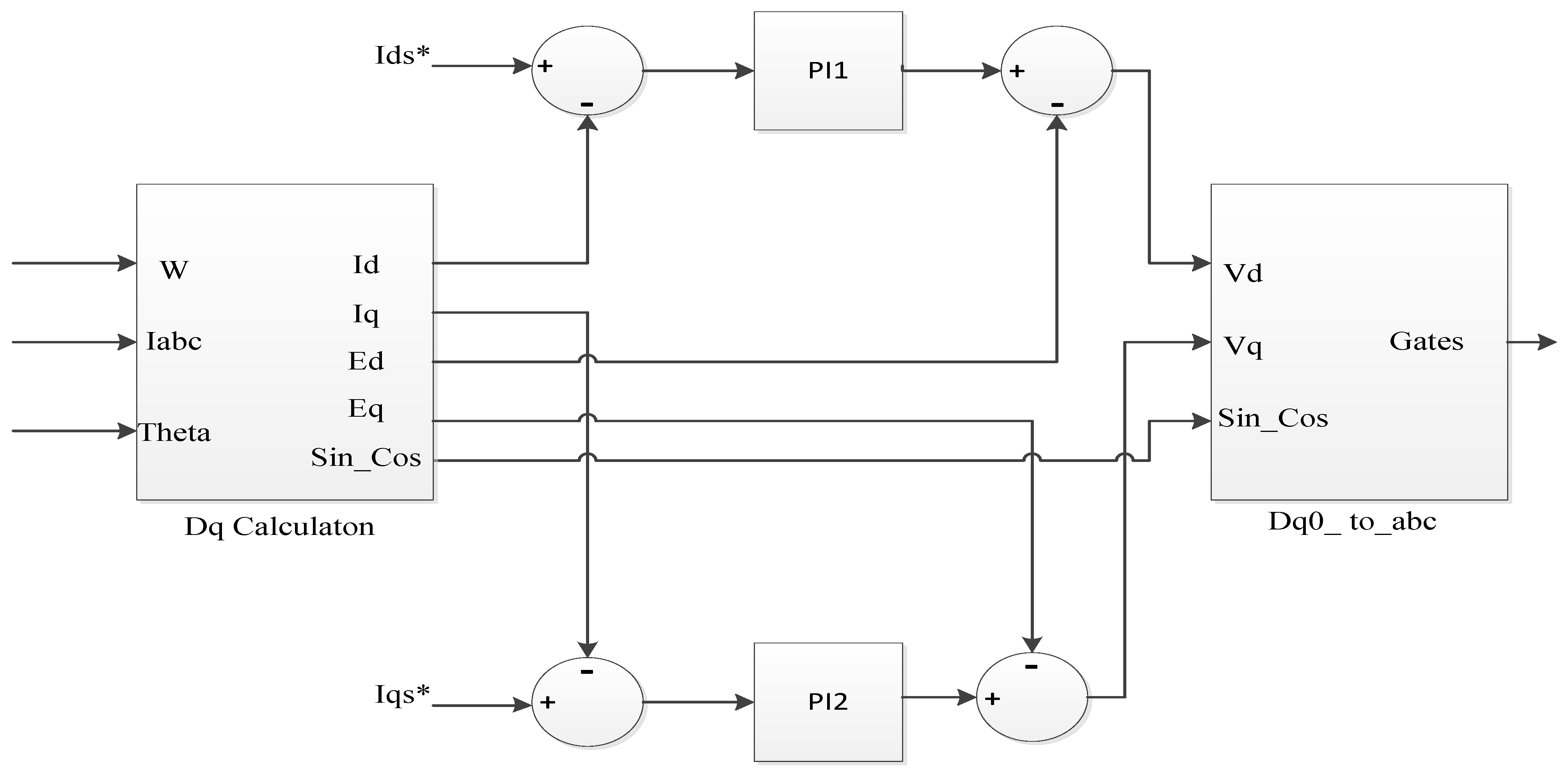
In this paper, we employed a cascaded control approach for each converter, where every converter consists of two inner loops for current control and two outer loops for DC and AC voltage control. The initial converter we focused on is referred to as the machine-side converter (MSC). In this case, the q-axis current of the converter is directly proportional to the active power. To maximize the power supplied to the DC bus, we selected the active power reference, Pref, accordingly. The control configuration for the MSC, primarily utilized to regulate the turbine speed and extract optimal power, is illustrated in Figure 2.
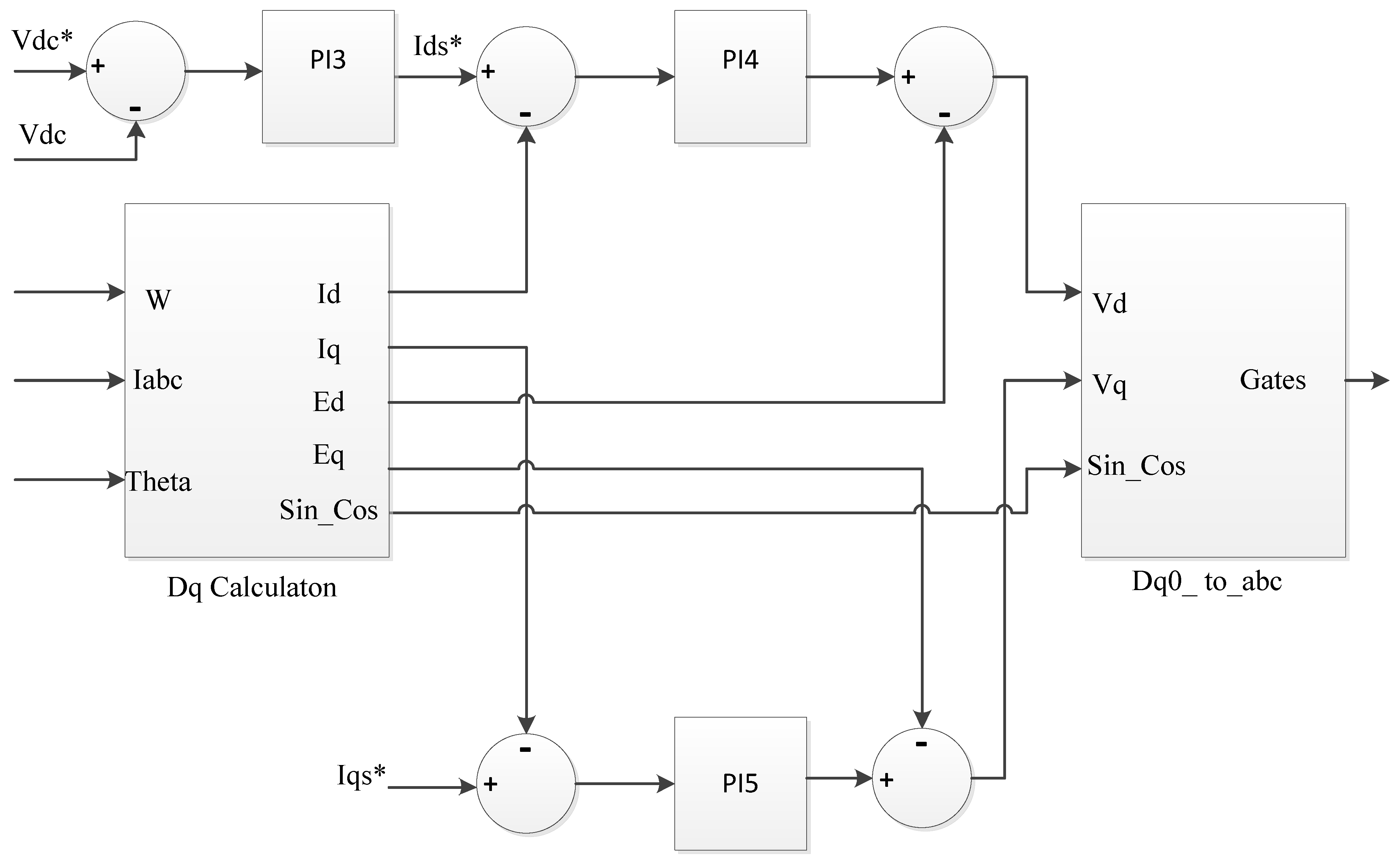
The second converter that is connected to the AC bus is referred to as the grid side converter (GSC). Its primary function is to regulate the dc-link capacitor and inject active and reactive power into the grid. In this case, the d-axis current is utilized to control the dc bus voltage, while the q-axis current governs the reactive power. The specific details of the controller configuration can be found in Figure 3.

2.2. VSC-BASED HVDC Transmission Construction

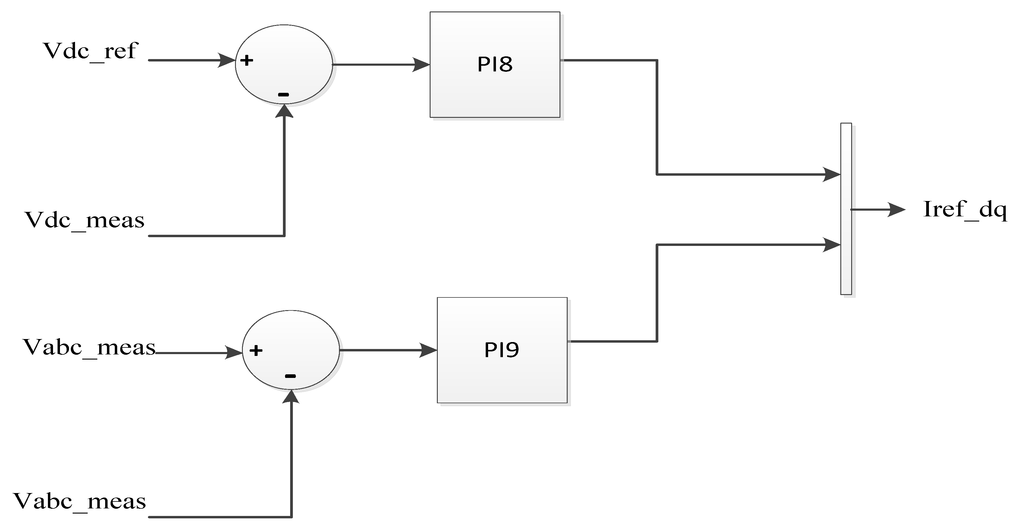
The well-established cascaded control method was employed to regulate the grid-side inverter of a wind farm. By utilizing the d-axis current, it becomes possible to control the DC voltage of the DC bus. Similarly, the q-axis current control allows for the maintenance of a constant terminal voltage at the high-voltage side of the transformer, aligning it with the desired reference level. This, in turn, facilitates control over the reactive power of the wind farm AC-bus. It is worth noting that the inner current control configuration for both onshore and offshore applications remained consistent, and you can refer to Figure 4 for further details. Additionally, Figure 5 provides a clear explanation of the outer voltage control loop.
The first VSC station (S.E), which is connected to the wind farm from the AC bus side, is equipped with four control circuits. These circuits consist of two inner loops utilizing PI controllers with specific parameter gains, namely kp4, and ki4, to regulate the currents isd and isq. In addition, there are two outer loops responsible for maintaining a constant Vdc at the transmission system S.E and governing the AC voltage at the wind farm terminals. The outer loop for DC voltage control employs PI gains kp5 and ki5, while the outer controller for AC voltage utilizes PI gains kp6 and ki6.
The next VSC, referred to as the receiving end converter (R.E.), is connected to the shore grid. The design of the onshore converter installed on the AC grid side is identical to the one used on the sending side but with different coefficient gains. Specifically, kp7 and ki7 represent the gains of the inner current loops, kp8, and ki8 are associated with the DC link voltage controller, and kp9 and ki9 govern the AC voltage controller. The controller architecture for the onshore VSC station at the R.E. is similar to that of the offshore VSC station at the S.E.
All voltage equations for VSC (rectifier and inverter) for offshore stations and onshore stations can be found in [40].

3. Optimization Algorithms

Optimization algorithms are methods applied to many problems as they give a solution close to the best optimal result. Meta-heuristic algorithms are powerful tools used to solve a problem independent of its nature and do not need a derivative. That makes meta-heuristic algorithms a suitable and strong method to find optimal solutions for the given optimization problem.
Meta-heuristic optimization algorithms can be categorized into physics-based, human-based, and evolutionary-based algorithms [41]. Evolutionary algorithms are inspired by biology as mutation and cross-over. The famous evolutionary algorithm based on the crossover is the genetic algorithm and it is restricted for exploration that causes slow convergence. The physics-based algorithm is inspired by physics law in nature, like Equilibrium optimizer [42,43] and gravitational search algorithm. The human-based meta-heuristic algorithm is inspired by human interactions and human behavior as teaching–learning-based optimization [37].
To achieve optimal results, meta-heuristic optimization algorithms depend on two fundamental elements: exploration and exploitation [44]. Exploration enables a global search across space, which helps to prevent becoming trapped in local optima. Exploitation enhances optimal solutions through local search.
The study employed two fitness functions to optimize the wind system and get the optimal point. The first fitness function is the integral square of error (ISE) of DC voltage across the capacitor. The second fitness function considers the non-linear nature of the system model and is based on the ISE of Vdc of the transmission line and the root mean square (R.M.S) at the point of common coupling (PCC). These functions are represented by cost function Equations (2) and (3).
Fitness = I S E 1 = V d c , r e f V d c 2   d t
Fitness = I S E 2 = V d c , r e f V d c 2   d t + V p c c , r e f V p c c 2   d t

3.1. HPSOGSA Overview

A novel hybrid population-based algorithm called PSOGSA was introduced, which combines the strengths of particle swarm optimization (PSO) and gravitational search algorithm (GSA). The primary concept is to merge PSO’s exploitation capability with GSA’s exploration ability, effectively harnessing the advantages of both algorithms.
The hybrid approach is considered low-level due to integrating functionalities from both algorithms. It is classified as co-evolutionary since the algorithms operate in parallel rather than sequentially. In other words, they concurrently contribute to the overall solution. Additionally, the hybrid approach is deemed heterogeneous as it utilizes two distinct algorithms collaborating to generate the final results.
The primary objective of optimization techniques is to discover the optimal solution from a range of potential inputs [45]. This is achieved by incorporating two crucial attributes: exploration and exploitation, to strike a balance between exploration and exploitation, thus ensuring a comprehensive exploration of the search space while leveraging the potential of promising solutions. The ultimate aim is to strike a harmonious balance between exploration and exploitation to identify the global optimum [42] effectively.
The exploration capability of algorithms involves exploring various regions within a problem space, while exploitation refers to the ability to converge toward the best solution near a promising solution.
PSO is inspired by the social behavior of bird flocking. It employs a group of particles (representing candidates’ solutions) to explore the search space and determine the optimal solution. Throughout this process, particles constantly refer to the best solution encountered thus far. In essence, particles take into account their own best solutions, as well as the global best solution. Each particle in PSO adjusts its position based on factors such as the current position, current velocity, distance to its (pbest), and distance to the (gbest).
GSA draws inspiration from Newton’s theory, which states that particles in the universe exert gravitational forces on each other based on their masses and the distance between them. In GSA, the algorithm can be seen as a group of agents (representing candidate solutions) whose masses are proportional to their fitness values [46]. Throughout the generations, these masses mutually attract each other through gravitational forces. Heavier masses exert stronger attraction forces, indicating that masses with higher fitness values, potentially closer to the global optimum, attract other masses in proportion to their distances.
Hybrid PSOGSA is proposed by combining PSO (inspired by bird flocking) and GSA (inspired by Newton’s physical theory on mass and particles). The goal of hybridization is to use the powerful exploration in PSO and powerful exploitation in GSA and make them work in parallel to improve their performance, robustness, or convergence speed.

3.2. HPSOGSA Procedure

The proposed algorithm incorporates an objective function that utilizes uses Equations (2) and (3) where, for each variable, lower and upper boundaries are given. PSO was mathematically modeled as follows:
v i t + 1 = w v i t + c 1 × r a n d × p b e s t i x i t + c 2 × r a n d × ( g b e s t x i t )
x i t + 1 = x i t + v i t + 1
The velocity of particle i at iteration t, denoted as v i t , is determined by a weighting function w, a weighting factor cj, a random number rand (ranging from 0 to 1), the current position of particle i at iteration t, represented as x i t , (pbesti) of agent i at iteration t, and the best solution encountered thus far, known as gbest.
The initial component of Equation (4), w v i t , contributes to the exploration capability of PSO. The subsequent parts, c1 × rand × (pbest x i t ) and c2 × rand × (gbest x i t ), correspond to the individual decision-making and collaborative aspects of the particles. The PSO algorithm commences by randomly distributing the particles within the problem space. During each iteration, the velocities of the particles are computed using Equation (4), while the position of the particles can be updated using Equation (5). This process iterates until a specified termination criterion is met.
The mathematical model of GSA is represented by Equation (5). In context of system consisting of N agents, the algorithm begins by randomly dispersing all agents within the search space. During each epoch, the gravitational forces between agent j and agent i at specific time are calculated using Equation (6).
F i j d t = G t   M p i ( t ) × M a j ( t ) R i t t + Ԑ × ( x j d ( t ) x j d ( t ) )
In Equation (7), Maj represents the active gravitational mass attributed to agent j, Mpi represents the passive gravitational mass associated with agent i. The term G(t) within Equation (7) denotes the gravitational constant at time t. Additionally, ε is a small constant, and D(t) represents the Euclidean distance between agents i and j.
G t = G o × e x p ( α × i t e r m a x i t e r )
In Equation (8), α represents the descending coefficient, while Go represents the initial value. The variables iter and maxiter corresponds to the current iteration and maximum number of iterations, respectively. Within a problem space with the dimension d, the calculation of the total force that acts on agent I is determined by Equation (8).
F i d t = j 1 , j i N r a n d j × F i j d ( t )
In the given equation, randj represents a random number between 0 and 1. Following the law of motion, the acceleration of an agent is proportional to the resultant force and inversely proportional to its mass. Consequently, the acceleration of all agents is computed using Equation (9).
a c i d t = F i d ( t ) M i i ( t )
The variable t represents a specific time, and Mi represents the mass of object i. The velocities and positions of the agents are determined using Equations (10) and (11).
v e l i d t + 1 = r a n d i × v e l i d ( t ) × a c i d ( t )
x i d t + 1 = x i d t + v e l i d ( t + 1 )
where randi is a random number within the range between 0 and 1. In the context of GSA, the algorithm commences by initializing all masses with random values, where each mass represents a candidate solution. Following the initialization phase, velocities for all masses are determined using Equation (10). Simultaneously, the gravitational constant, total forces, and accelerations are calculated as shown in Equations (7)–(9), respectively. The positions of masses are subsequently using Equation (11). Finally, the GSA algorithm is terminated upon satisfying a specified termination criterion.
The fundamental concept behind PSOGSA is to integrate the social thinking capability (gbest) from PSO with the local search ability of GSA. To achieve this amalgamation, Equation (12) is proposed as follows:
V i t + 1 = w × V i t + c 1 × r a n d × a c i ( t ) + c 2 × ( g b e s t X i ( t ) )
In the given Equation, V i t represents the velocity of agent i at iteration t c 1 denotes a weighting factor, w is a weighting function, rand is a random number between 0 and 1, a c i ( t ) and gbest refers to the acceleration of agent i at iteration t, and the best solution thus far. The positions of the particles are updated using a specified method. using Equation (13):
X i t + 1 = X i t + V i ( t + 1 )
In PSOGSA, the initial step involves random initialization of all agents, with each agent representing a candidate solution. Following the initialization, the gravitational force, gravitational constant, and resultant forces among the agents are computed using Equations (6)–(8), respectively. Subsequently, the accelerations of the particles are determined using Equation (9). In each iteration, the best solution encountered thus far is updated. Once the accelerations and the best solution have been updated, the velocities of all agents can be calculated using Equation (12). Finally, the positions of the agents are defined using Equation (13). The process of updating velocities and positions continues until a specified termination criterion is met.
The updating procedure takes into account the quality of solutions (fitness). Agents close to good solutions endeavor to attract other agents that are exploring the search space. When all agents are near a good solution, their movements become sluggish. In such instances, gBest assists in exploiting the global best solution. PSOGSA employs a memory (gBest) to store the best solution found thus far, ensuring its accessibility at any time. Each agent has access to this gBest and tends to move towards it. By adjusting the values of c 1 and c 2 , the balance between global search and local search abilities can be achieved.
Figure 6 illustrates the procedural steps involved in the HPSOGSA technique, which can be outlined in the following steps:
  • Initiate population;
  • Calculate the fitness function for all candidates;
  • Update G and gbest for the population;
  • Calculate M, forces and acceleration for all agents;
  • Update velocity and positions;
  • Check meeting criterion;
  • Return the best optimal solution.
This configuration is used while tuning FOPID using HPSOGSA in Table 1.
Figure 6. The representation of the flowchart of the HPSOGSA algorithm.
Sustainability 15 11912 g006

4. FOPID Settings

FOPID stands for fractional order proportional integral derivative controller. FOPID can be used for multivariable process control systems. FOPID or PIλDμ has five parameters: Kp, Ki, Kd, λ, and μ. Compared to conventional PID, there are two additional parameters. FOPID is based on fractional calculus and is included in many works in different areas of science and engineering.
Due to its simplicity and stability, PID controllers are the most frequently utilized in industrial applications. But also, PID has some cons as it is susceptible to system variations. Several types of research have been carried out to develop PID and overcome this limitation. FOPID is an extension of classical PID for process control [47]. FOPID is less sensitive to system fluctuations and proved its effectiveness in this study compared to classical PI controllers.
The FOPID transfer function can be described in Equation (14), where this controller is more complex than the classical PID controller due to increased parameters. Five parameters have to be tuned.
G c S = K p + K i S γ + K d S μ
In this study, the HPSOGSA technique was used to tune the five parameters of FOPID and compared with the PI controller tuned by genetic algorithm and grey wolf optimizer. In Table 2 and Table 3, the setting parameter for FOPID is tuned by HPSOGSA and GA, respectively. Also, the parameter configuration for the PI controller tuned by GA and GWO is found in Table 4.

5. Simulation Results

In this study, the FOPID controller was tuned using the HPSOGSA technique and compared with the PI controller tuned using GA and GWO techniques. The simulation lasted for seven seconds with a constant wind speed of 12 m/s. As demonstrated in Figure 1, both symmetrical and asymmetrical faults were assigned to an offshore wind farm (OWF) after 4.1 s from the beginning of operating at PCC2. The faulty line circuit breaker was opened at 4.22 s and closed at 5.5 s in four different scenarios. Also, FOPID was tuned using GA and compared with the HPSOGSA algorithm where HPSOGSA showed superiority over GA relating to system response (MPOS, MPUS, and settling time).

5.1. Comparison between FOPID-Based HPSOGSA and PI-Based GA and GWO

5.1.1. Case 1 Symmetrical Fault (3 Line to Ground Fault)

The effectiveness of FOPID tuned with HPSOGSA was demonstrated compared to PI controller tuned with GA and GWO, as illustrated in Figure 7 and Figure 8 regarding the terminal AC voltage connected to the grid at PCC2 and the DC voltage, respectively. HPSOGSA outperformed other methods by exhibiting shorter settling time, less oscillation, and lower peak overshoot during a severe three-phase to ground fault at PCC2.
Figure 7 illustrates the improved transient stability of the PCC2 voltage using the FOPID tuned with HPSOGSA and a shorter settling time compared to the PI controller tuned with GA and GWO. FOPID also showed less oscillation and peak overshoot than the PI controller. The voltage response using the proposed controller reached a steady-state error at 5.5 s, while GA reached it after 7 s, and GWO reached it at 5.4 s. Additionally, HPSOGSA exhibited less oscillation compared to GWO and GA. Figure 8 demonstrates the dc link voltage response using the HPSOGSA technique in tuning FOPID over classical PI controllers with GA and GWO. FOPID with HPSOGSA exhibited shorter transient time, fewer oscillations, and less overshot than PI. Also, FOPID had lower oscillations and peak overshoot compared to the PI controller. The steady-state error for GA was reached at 5.3 s and 6.8 s for GWO, while HPSOGSA reached it at 4.7 s. Thus, the effectiveness of FOPID tuned with HPSOGSA was proven compared to the PI controller tuned with GA and GWO.

5.1.2. Case 2 Asymmetrical Fault (2 Line to Ground Fault)

Figure 9 and Figure 10 demonstrate the superior effectiveness of FOPID tuned with HPSOGSA compared to PI controller tuned with GA and GWO under a double line to ground fault condition. In Figure 9, FOPID exhibited improved transient stability and a shorter settling time than the PI controller, with less oscillation and peak overshoot. The HPSOGSA reached steady-state error at 5.5 s, GA reached it after 7 s, and GWO at 5.5 s. Additionally, HPSOGSA exhibited less oscillation compared to GWO and GA. Figure 10 illustrates the dc link voltage response using the FOPID tuned with HPSOGSA had a shorter transient time, fewer oscillations, and lower overshoot than the PI controller. The steady-state error for GA was reached at 5.3 s and 6.8 s for GWO, while HPSOGSA reached it at 4.7 s. Thus, the effectiveness of FOPID tuned with HPSOGSA was proven over the PI controller tuned with GA and GWO. These findings were supported by the performance of terminal ac voltage linked to the grid at PCC2 and the DC voltage, as shown in Figure 9 and Figure 10.

5.1.3. Case 3 Asymmetrical Fault (Line to Ground Fault)

FOPID tuned with HPSOGSA was more effective than PI controller tuned with GA and GWO, as demonstrated in Figure 11 and Figure 12. In Figure 11, FOPID showed improved transient stability and a shorter settling time than the PI controller, with less oscillation and peak overshoot. HPSOGSA reached a steady-state error at 5.5 s, while GA reached it after 7 s, and GWO reached it at 5.5 s, and HPSOGSA also exhibited less oscillation compared to GWO and GA. Figure 12 showed that FOPID tuned with HPSOGSA had shorter transient time, fewer oscillations, and peak overshoot than the PI controller. The steady-state error for GA was reached at 5.3 s and 6.8 s for GWO, while HPSOGSA reached it at 4.7 s. These results demonstrate the effectiveness of FOPID tuned with HPSOGSA over the PI controller tuned with GA and GWO. Additionally, Figure 11 and Figure 12 supported these findings by showing the superior performance of terminal ac voltage linked to the grid at PCC2 and the DC voltage.

5.1.4. Case 4 Asymmetrical Fault (Line to Line Fault)

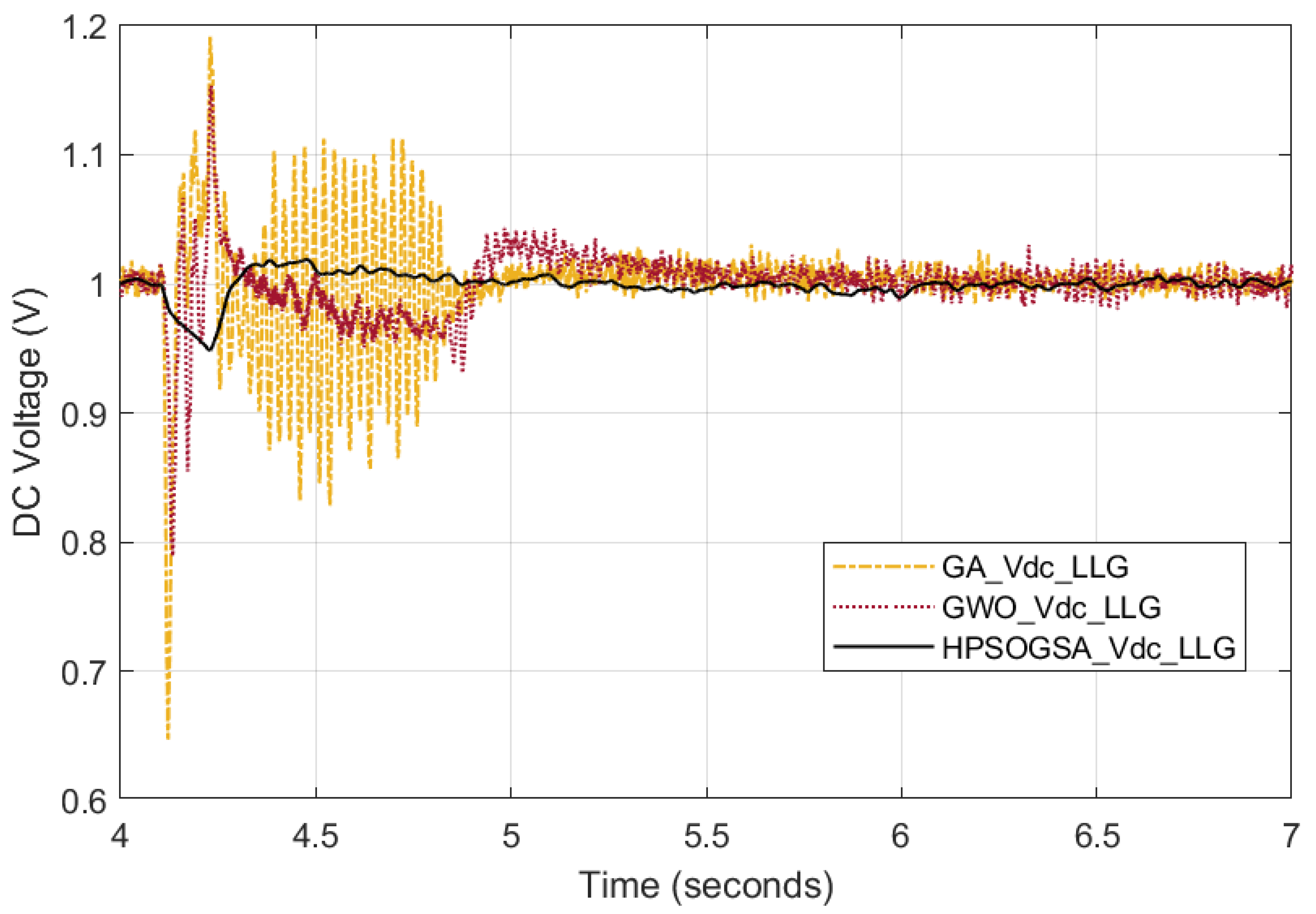
FOPID tuned by HPSOGSA proved to be effective over PI controller tune using GA and GWO. Figure 13 and Figure 14 show terminal ac voltage linked to the grid at PCC2 and DC voltage, respectively. HPSOGSA outperformed other methods regarding settling time, oscillation, and peak overshoot during a phase-to-phase fault at PCC2. Figure 13 clarifies the superiority of the HPSOGSA technique in tuning FOPID compared to classical PI controllers with GA and GWO. FOPID with HPSOGSA had less transient time than GA-based PI and GWO-based PI. Also, FOPID has lower oscillations and peak overshoot compared to the PI controller. GA reached a steady state error at 4.8 s while GWO reached 5 s in the case of PI. HPSOGSA reached a steady state error at 4.3 s. FOPID proved to be effective when tuned with HPSOGSA compared to the PI controller tuned with GA and GWO.
Figure 14 shows that FOPID tuned with HPSOGSA improve transient stability. Also, settling time was small compared to the PI controller tuned with GA and GWO. Less oscillation and peak overshoot in the case of FOPID was demonstrated. HPSOGSA reached steady-state error at 4.8 s, GA reached it after 5 s, and GWO reached it at 5.2 s. HPSOGSA had less oscillation compared to GWO and GA.

5.2. Comparison between FOPID-Based HPSOGSA and PI-Based GA and GWO

5.2.1. Case 1 Symmetrical Fault (3 Line to Ground Fault)

Figure 15 and Figure 16 demonstrate the superior effectiveness of FOPID tuned with HPSOGSA compared to and tuned with GA. In Figure 15, HPSOGSA exhibited improved transient stability and a shorter settling time than the GA, with less oscillation and peak overshoot. The HPSOGSA reached steady-state error at 4.8 s, and GA at 5 s. Additionally, HPSOGSA exhibited less oscillation compared to GA. Figure 16 illustrates that FOPID tuned with HPSOGSA had a shorter transient time, fewer oscillations, and low overshoot than with GA. The steady-state error for GA was reached at 5.5 s, while HPSOGSA reached it at 5 s. Thus, the effectiveness of FOPID tuned with HPSOGSA was proven over with GA These findings were supported by the performance of terminal ac voltage linked to the grid at PCC2 and the DC voltage.

5.2.2. Case 2 Asymmetrical Fault (2 Line to Ground Fault)

Figure 17 and Figure 18 demonstrate the superior effectiveness of FOPID tuned with HPSOGSA compared to and tuned with GA. In Figure 17, HPSOGSA exhibited improved transient stability and a shorter settling time than the GA, with less oscillation and peak overshoot. The HPSOGSA reached steady-state error at 4.5 s, and GA at 4.8 s. Additionally, HPSOGSA exhibited less oscillation compared to GA. Figure 18 illustrates that FOPID tuned with HPSOGSA had a shorter transient time, fewer oscillations, and low overshoot than with GA. The steady-state error for GA was reached at 5 s, while HPSOGSA reached it at 4.6 s. Thus, the effectiveness of FOPID tuned with HPSOGSA was proven over with GA. These findings were supported by the performance of terminal ac voltage linked to the grid at PCC2 and the DC voltage.

5.2.3. Case 3 Asymmetrical Fault (Line to Ground Fault)

Figure 19 and Figure 20 demonstrate the superior effectiveness of FOPID tuned with HPSOGSA compared to and tuned with GA. In Figure 19, HPSOGSA exhibited improved transient stability and a shorter settling time than the GA, with less oscillation and peak overshoot. The HPSOGSA reached steady-state error at 4.5 s, and GA at 5 s. Additionally, HPSOGSA exhibited less oscillation compared to GA. Figure 20 illustrates that FOPID tuned with HPSOGSA had a shorter transient time, fewer oscillations, and low overshoot than with GA. The steady-state error for GA was reached at 5.5 s, while HPSOGSA reached it at 5 s. Thus, the effectiveness of FOPID tuned with HPSOGSA was proven over with GA. These findings were supported by the performance of terminal ac voltage linked to the grid at PCC2 and the DC voltage.

5.2.4. Case 4 Asymmetrical Fault (Line to Line Fault)

Figure 21 and Figure 22 demonstrate the superior effectiveness of FOPID tuned with HPSOGSA compared to and tuned with GA. In Figure 21, HPSOGSA exhibited improved transient stability and a shorter settling time than the GA, with less oscillation and peak overshoot. The HPSOGSA reached steady-state error at 4.8 s, and GA at 5 s. Additionally, HPSOGSA exhibited less oscillation compared to GA. Figure 22 illustrates that FOPID tuned with HPSOGSA had a shorter transient time, fewer oscillations, and low overshoot than with GA. The steady-state error for GA was reached at 5.5 s, while HPSOGSA reached it at 5 s. Thus, the effectiveness of FOPID tuned with HPSOGSA was proven over with GA. These findings were supported by the performance of terminal ac voltage linked to the grid at PCC2 and the DC voltage.

6. Conclusions

This study proposed a design technique utilizing the HPSOGSA algorithm for regulating the FOPID controller gains in converters used in the OWF system. When tuning PI controllers in the cascaded control loop for each VSC converter, the newly suggested system’s effectiveness was compared with GWO and GA algorithms. The results demonstrated that the HPSOGSA algorithm surpassed the other methods concerning system response (Ts, MPOS, and MPUS) under network disturbance. The FOPID controller was more effective than the PI controller used in cascaded control loops, as it exhibited greater robustness and flexibility due to its two additional degrees of freedom. This conclusion was validated for OWFs tied to the electrical grid through VSC-based HVDC and VSWT-PMSG under different fault contingencies. The HPSOGSA algorithm was also faster in recovering from faults and more stable than other tuning algorithms. The simulation results mimicked the strength of the HPSOGSA optimizer for OWFs system under various disturbances. In addition, the proposed algorithm improved the system’s response to transient conditions and disturbances compared to GA and GWO. According to this study, the algorithm introduced with the proposed controller has the potential to be implemented in future research related to areas like smart grids and microgrids.

Author Contributions

N.A.M., A.O.B., and H.M.H.: conceptualization and methodology, A.A., and F.J.: validation, formal analysis, T.A.: investigation, visualization, H.M.H. and F.J.: review and editing. All authors have read and agreed to the published version of the manuscript.

Funding

This work was supported by King Saud University, Riyadh, Saudi Arabia.

Institutional Review Board Statement

Not applicable.

Informed Consent Statement

Not applicable.

Data Availability Statement

Not applicable.

Acknowledgments

This work was supported by the Researchers Supporting Project number (RSP2023R258), King Saud University, Riyadh, Saudi Arabia.

Conflicts of Interest

The authors declare no conflict of interest.

Nomenclature

LCCLine Commutated Converter
DFIGDoubly Fed Induction Generator
MPPTMaximum PowerPoint Tracking
WECSWind Energy Conversion System
PIProportional Integral Controller
PIDProportional Integral Differential Controller
GAGenetic Algorithm
GWOGrey Wolf Optimizer
FRTFault Ride Through
EOEquilibrium Optimizer
HVDCHigh Voltage Direct Current Transmission
FOPIDFractional Order PID Controller
VSCVoltage Source Converter
OWFOffshore Wind Farm
IAEIntegral Absolute Error
ITAEIntegral Time Absolute Error
ITSEIntegral Time Square Error
FLCFuzzy Logic Controller
CMPNContinuous Mixed P-Norm
CNNConvolutional Neural Networks
ANNArtificial Neural Network
SMESSuperconducting Magnetic Energy System
LMSLeast Mean Square
LMSRELeast Mean Square Root Error
PCCPoint of Common Coupling
S.ESending End
GSCGrid Side Converter
MSCMachine Side Converter
VSWTVariable Speed Wind Turbine
ITLOInteractive Teaching Learning Optimizer
TLBOTeaching Learning Based Optimizer
HPSOGSAHybrid Particle Swarm and Gravitational Search Algorithm

References

  1. Xia, S.; Zhang, Q.; Hussain, S.T.; Hong, B.; Zou, W. Impacts of integration of wind farms on power system transient stability. Appl. Sci. 2018, 8, 1289. [Google Scholar] [CrossRef] [Green Version]
  2. GWEC. Global Wind Report 2021 | Global Wind Energy Council; Global Wind Energy Council: New York, NY, USA, 2021. [Google Scholar]
  3. Liu, X.; Xu, Z. Coordinated Frequency Control Scheme of Offshore Wind Farm Connected to VSC-HVDC. Electr. Power Components Syst. 2019, 47, 757–771. [Google Scholar] [CrossRef]
  4. Zeng, R.; Wang, Y. Improved Frequency Control Strategy for Offshore Wind Farm Integration via VSC-HVDC. Energies 2022, 15, 6363. [Google Scholar] [CrossRef]
  5. Rabie, D.; Senjyu, T.; Alkhalaf, S.; Mohamed, Y.S.; Shehata, E.G. Study and analysis of voltage source converter control stability for HVDC system using different control techniques. Ain Shams Eng. J. 2021, 12, 2763–2779. [Google Scholar] [CrossRef]
  6. Jing, T.; Maklakov, A.S. A Review of Voltage Source Converters for Energy Applications. In Proceedings of the 2018 International Ural Conference on Green Energy (UralCon), Chelyabinsk, Russia, 4–6 October 2018; pp. 275–281. [Google Scholar] [CrossRef]
  7. Hassoine, M.A.; Lahlou, F.; Addaim, A.; Madi, A.A. Wind farm layout optimization using real coded multi-population genetic algorithm. In Proceedings of the 2019 International Conference on Wireless Technologies, Embedded and Intelligent Systems (WITS), Fez, Morocco, 3–4 April 2019; pp. 1–5. [Google Scholar] [CrossRef]
  8. Yuan, C.; Liu, D.-D.; Zhu, Y.-J.; Zeng, T.; Jiang, B.-X.; Tang, C.-X.; Zhou, Y.; He, J.-L. Effect of charge transport on electrical degradation in polypropylene/organic molecular semiconductor composites for HVDC cable insulation. Appl. Phys. Lett. 2023, 122, 112904. [Google Scholar] [CrossRef]
  9. Oni, O.E.; Mbangula, K.I.; Davidson, I.E. A Review of LCC-HVDC and VSC-HVDC Technologies and Applications. Trans. Environ. Electr. Eng. 2016, 1, 68. [Google Scholar] [CrossRef] [Green Version]
  10. Ju, Y.F.; Zhu, C.W. The control method and experimental study of HVDC light inverter part. In Proceedings of the 2010 6th International Conference on Wireless Communications Networking and Mobile Computing (WiCOM), Chengdu, China, 23–25 September 2010; pp. 2–5. [Google Scholar] [CrossRef]
  11. Bozhko, S.; Blasko-Gimenez, R.; Li, R.; Clare, J.C.; Asher, G.M. Control of offshore DFIG-based wind farm grid with line-commutated HVDC connection. In IEEE Transactions on Energy Conversion; IEEE: Piscateville, NJ, USA, 2007; pp. 1563–1568. [Google Scholar] [CrossRef]
  12. Ma, X.; Liao, Z.; Wang, Y.; Zhao, J. Fast Dynamic Phasor Estimation Algorithm Considering DC Offset for PMU Applications. In IEEE Transactions on Power Delivery; IEEE: Piscateville, NJ, USA, 2023. [Google Scholar]
  13. Chaithanya, S.; Reddy, V.N.B.; Kiranmayi, R. Modeling & analysis of grid-tied PMA based offshore wind energy system using PSCAD/EMTDC. Ain Shams Eng. J. 2019, 10, 411–417. [Google Scholar] [CrossRef]
  14. Alaboudy, A.H.K.; Daoud, A.A.; Desouky, S.S.; Salem, A.A. Converter controls and flicker study of PMSG-based grid connected wind turbines. Ain Shams Eng. J. 2013, 4, 75–91. [Google Scholar] [CrossRef] [Green Version]
  15. Basak, R.; Bhuvaneswari, G.; Pillai, R.R. Low-Voltage Ride-Through of a Synchronous Generator-Based Variable Speed Grid-Interfaced Wind Energy Conversion System. IEEE Trans. Ind. Appl. 2020, 56, 752–762. [Google Scholar] [CrossRef]
  16. Ma, X.; Wan, Y.; Wang, Y.; Dong, X.; Shi, S.; Liang, J.; Zhao, Y.; Mi, H. Multi-Parameter Practical Stability Region Analysis of Wind Power System Based on Limit Cycle Amplitude Tracing. IEEE Trans. Energy Convers. 2023. [Google Scholar] [CrossRef]
  17. Xu, L.; Andersen, B.R. Grid connection of large offshore wind farms using HVDC. Wind. Energy 2006, 9, 371–382. [Google Scholar] [CrossRef]
  18. Mahvash, H.; Taher, S.A.; Rahimi, M. A new approach for power quality improvement of DFIG based wind farms connected to weak utility grid. Ain Shams Eng. J. 2017, 8, 415–430. [Google Scholar] [CrossRef] [Green Version]
  19. Nasiri, M.; Milimonfared, J.; Fathi, S.H. Modeling, analysis and comparison of TSR and OTC methods for MPPT and power smoothing in permanent magnet synchronous generator-based wind turbines. Energy Convers. Manag. 2014, 86, 892–900. [Google Scholar] [CrossRef]
  20. Mishra, S.; Shukla, S.; Verma, N.; Ritu, R. Comprehensive review on Maximum Power Point Tracking techniques: Wind Energy. In Proceedings of the 2015 Communication, Control and Intelligent Systems (CCIS), Mathura, India, 7–8 November 2015; pp. 464–469. [Google Scholar] [CrossRef]
  21. Jeba, P.; Selvakumar, A.I. FOPID based MPPT for photovoltaic system. Energy Sources Part A Recover. Util. Environ. Eff. 2018, 40, 1591–1603. [Google Scholar] [CrossRef]
  22. Chaib, L.; Choucha, A.; Arif, S. Optimal design and tuning of novel fractional order PID power system stabilizer using a new metaheuristic Bat algorithm. Ain Shams Eng. J. 2017, 8, 113–125. [Google Scholar] [CrossRef] [Green Version]
  23. Mahmoud, E.A.; Nasrallah, M.; Soliman, H.F.; Hasanien, H.M. Fractional order PI controller based on hill climbing technique for improving MPPT of the BDF-RG driven by wind turbine. In Proceedings of the 2017 Nineteenth International Middle East Power Systems Conference (MEPCON), Cairo, Egypt, 19–21 December 2017. [Google Scholar] [CrossRef]
  24. Pradhan, R.; Majhi, S.K.; Pradhan, J.K.; Pati, B.B. Optimal fractional order PID controller design using Ant Lion Optimizer. Ain Shams Eng. J. 2010, 11, 281–291. [Google Scholar] [CrossRef]
  25. Shawqran, A.M.; El-Marhomy, A.; Attia, M.A.; Kamh, M.Z. Novel blade angle controllers techniques based on heuristics algorithms. Ain Shams Eng. J. 2022, 13, 101782. [Google Scholar] [CrossRef]
  26. Gouda, M.M.; Danaher, S.; Underwood, C.P. Fuzzy Logic Control Versus Conventional PID Control for Controlling Indoor Temperature of a Building Space. IFAC Proc. Vol. 2000, 33, 249–254. [Google Scholar] [CrossRef]
  27. Rubaai, A.; Castro-Sitiriche, M.J.; Ofoli, A.R. Design and implementation of parallel fuzzy PID controller for high-performance brushless motor drives: An integrated environment for rapid control prototyping. IEEE Trans. Ind. Appl. 2008, 44, 1090–1098. [Google Scholar] [CrossRef]
  28. Muyeen, S.M.; Al-Durra, A. Modeling and control strategies of fuzzy logic controlled inverter system for grid interconnected variable speed wind generator. IEEE Syst. J. 2013, 7, 817–824. [Google Scholar] [CrossRef] [Green Version]
  29. Yin, X.; Zhao, X. Deep Neural Learning Based Distributed Predictive Control for Offshore Wind Farm Using High-Fidelity les Data. IEEE Trans. Ind. Electron. 2021, 68, 3251–3261. [Google Scholar] [CrossRef]
  30. Qais, M.H.; Hasanien, H.M.; Alghuwainem, S. A novel LMSRE-based adaptive PI control scheme for grid-integrated PMSG-based variable-speed wind turbine. Int. J. Electr. Power Energy Syst. 2021, 125, 106505. [Google Scholar] [CrossRef]
  31. Hasanien, H.M.; Muyeen, S.M. Affine projection algorithm based adaptive control scheme for operation of variable-speed wind generator. IET Gener. Transm. Distrib. 2015, 9, 2611–2616. [Google Scholar] [CrossRef]
  32. Hussien, A.M.; Kim, J.; Alkuhayli, A.; Alharbi, M.; Hasanien, H.M.; Tostado-Véliz, M.; Turky, R.A.; Jurado, F. Adaptive PI Control Strategy for Optimal Microgrid Autonomous Operation. Sustainability 2022, 14, 14928. [Google Scholar] [CrossRef]
  33. Soliman, M.A.; Hasanien, H.M.; Al-Durra, A.; Alsaidan, I. A novel adaptive control method for performance enhancement of grid-connected variable-speed wind generators. IEEE Access 2020, 8, 82617–82629. [Google Scholar] [CrossRef]
  34. Amin, M.N.; Soliman, M.A.; Hasanien, H.M.; Abdelaziz, A.Y. Hybrid CSA-GWO Algorithm-Based Optimal Control Strategy for Efficient Operation of Variable-Speed Wind Generators; Springer International Publishing: Berlin/Heidelberg, Germany, 2021. [Google Scholar] [CrossRef]
  35. El-Naggar, M.F.; Mosaad, M.I.; Hasanien, H.M.; AbdulFattah, T.A.; Bendary, A.F. Elephant herding algorithm-based optimal PI controller for LVRT enhancement of wind energy conversion systems. Ain Shams Eng. J. 2021, 12, 599–608. [Google Scholar] [CrossRef]
  36. Younes, Z.; Alhamrouni, I.; Mekhilef, S.; Reyasudin, M. A memory-based gravitational search algorithm for solving economic dispatch problem in micro-grid. Ain Shams Eng. J. 2021, 12, 1985–1994. [Google Scholar] [CrossRef]
  37. Rao, R.V.; Savsani, V.J.; Vakharia, D.P. Teaching-learning-based optimization: A novel method for constrained mechanical design optimization problems. Comput. Aided Des. 2011, 43, 303–315. [Google Scholar] [CrossRef]
  38. Yang, B.; Yu, T.; Zhang, X.; Huang, L.; Shu, H.; Jiang, L. Interactive teaching-learning optimiser for parameter tuning of VSC-HVDC systems with offshore wind farm integration. IET Gener. Transm. Distrib. 2018, 12, 678–687. [Google Scholar] [CrossRef] [Green Version]
  39. Muyeen, S.M.; Takahashi, R.; Tamura, J. Operation and control of HVDC-connected offshore wind farm. IEEE Trans. Sustain. Energy 2010, 1, 30–37. [Google Scholar] [CrossRef]
  40. Mohamed, N.A.; Hasanien, H.M.; Al-Ammar, E.A.; Tostado-Véliz, M.; Turky, R.A.; Jurado, F.; Badr, A.O. Gorilla tropical optimization algorithm solution for performance enhancement of offshore wind farm. IET Gener. Transm. Distrib. 2022, 17, 2388–2400. [Google Scholar] [CrossRef]
  41. Behera, S.; Sahoo, S.; Pati, B.B. A review on optimization algorithms and application to wind energy integration to grid. Renew. Sustain. Energy Rev. 2015, 48, 214–227. [Google Scholar] [CrossRef]
  42. Faramarzi, A.; Heidarinejad, M.; Stephens, B.; Mirjalili, S. Equilibrium optimizer: A novel optimization algorithm. Knowl.-Based Syst. 2010, 191, 105190. [Google Scholar] [CrossRef]
  43. Nguyen, T.N.A.; Pham, D.C.; Huu, C.T.N.; Nguyen, A.N. Implementation of equilibrium optimizer algorithm for mppt in a wind turbine with pmsg. WSEAS Trans. Syst. Control. 2021, 16, 216–223. [Google Scholar] [CrossRef]
  44. Bakry, O.M.; Alhabeeb, A.; Ahmed, M.; Alkhalaf, S.; Senjyu, T.; Mandal, P.; Dardeer, M. Improvement of distribution networks performance using renewable energy sources based hybrid optimization techniques. Ain Shams Eng. J. 2022, 13, 101786. [Google Scholar] [CrossRef]
  45. Berus, L.; Hernavs, J.; Peršak, T.; Potočnik, D.; Klančnik, S.; Gotlih, J.; Karner, T.; Ficko, M. A New Hybrid PSO-JAYA Algorithm for Function Optimization. Lect. Notes Netw. Syst. 2023, 687, 62–68. [Google Scholar] [CrossRef]
  46. Rashedi, E.; Nezamabadi-pour, H.; Saryazdi, S. GSA: A Gravitational Search Algorithm. Inf. Sci. 2009, 179, 2232–2248. [Google Scholar] [CrossRef]
  47. Shah, P.; Agashe, S. Review of fractional PID controller. Mechatronics 2016, 38, 29–41. [Google Scholar] [CrossRef]
Figure 1. Block diagram of offshore wind farm.
Sustainability 15 11912 g001
Figure 2. Controller configuration for machine side converter.
Sustainability 15 11912 g002
Figure 3. Controller configuration for grid side converter.
Sustainability 15 11912 g003
Figure 4. Control block diagram for inner current control loop.
Sustainability 15 11912 g004
Figure 5. Control block diagram for outer voltage control loop.
Sustainability 15 11912 g005
Figure 7. RMS voltage of 3 line-to-ground fault.
Sustainability 15 11912 g007
Figure 8. DC voltage of 3 line-to-ground fault.
Sustainability 15 11912 g008
Figure 9. RMS voltage of double line-to-ground fault.
Sustainability 15 11912 g009
Figure 10. DC voltage of double line-to-ground fault.
Sustainability 15 11912 g010
Figure 11. RMS voltage at PCC2 of line-to-ground fault.
Sustainability 15 11912 g011
Figure 12. DC voltage of line-to-ground fault.
Sustainability 15 11912 g012
Figure 13. RMS voltage at PCC2 line-to-line fault.
Sustainability 15 11912 g013
Figure 14. DC voltage of line-to-line fault.
Sustainability 15 11912 g014
Figure 15. RMS voltage of 3 lines-to-ground fault.
Sustainability 15 11912 g015
Figure 16. DC voltage of 3 lines-to-ground fault.
Sustainability 15 11912 g016
Figure 17. RMS voltage of double line-to-ground fault.
Sustainability 15 11912 g017
Figure 18. DC voltage of double line-to-ground fault.
Sustainability 15 11912 g018
Figure 19. RMS voltage at PCC2 of line-to-ground fault.
Sustainability 15 11912 g019
Figure 20. DC voltage of line-to-ground fault.
Sustainability 15 11912 g020
Figure 21. RMS voltage at PCC2 line-to-line fault.
Sustainability 15 11912 g021
Figure 22. DC voltage of line-to-line fault.
Sustainability 15 11912 g022
Table 1. HPSOGSA Setting.
Lower Boundary0
Upper Boundary100
Population 10
Maximum Iteration20
Table 2. FOPID configuration using HPSOGSA.
FOPIDKpKiKDλμ
MSC17.32226.3322.230.80.8
27.32226.3322.230.80.8
GSC30.72.40.11230.920.95
417.33518.2420.20.880.98
517.33518.2420.20.880.98
Offhsore612.14560.2230.2980.891.05
727.526.90.5140.830.93
83.7530.4420.11840.9340.95
93.7530.4420.11840.9340.95
Onshore106.78511000.4230.880.92
112.10.540.6990.90.9
1212.77848.2250.1940.9720.95
1312.77848.2250.1940.9720.95
Table 3. FOPID configuration using GA.
FOPIDKpKiKDλμ
MSC117.2537.5564.250.920.83
217.2537.5564.250.920.82
GSC30.92.50.20.881.05
475.22482.8460.2560.90.95
575.22480.5230.2560.90.95
offhsore60.78989.2360.350.850.98
70.78989.2360.560.80.9
815.78520.2230.2230.90.88
92.52311.2250.2230.90.88
Onshore1039.2565.7780.4210.880.92
1139.2565.7780.50.920.88
12106.2230.30.950.9
132.25150.30.950.9
Table 4. PI controller configuration using GWO and GA.
PIGWOGA
KpKiKpKi
Wind StationPI 15.255727.374715.61875.6171
PI 25.255727.374715.61875.6171
PI 30.39862.90420.8581.959
PI 467.137487.844274.3182.846
PI 567.137487.844274.3182.846
Offshore StationPI 61.84635.84330.58987.937
PI 71.84635.84330.58987.937
PI 88.062296.997713.83518.179
PI 92.704215.32771.5879.689
Onshore StationPI 1034.874510037.82861.81
PI 1134.874510037.82861.81
PI 122.805232.24118.9557.995
PI 130.58714.96441.610
Disclaimer/Publisher’s Note: The statements, opinions and data contained in all publications are solely those of the individual author(s) and contributor(s) and not of MDPI and/or the editor(s). MDPI and/or the editor(s) disclaim responsibility for any injury to people or property resulting from any ideas, methods, instructions or products referred to in the content.