Article

Environmental Impact Assessment of Different Manufacturing Technologies Oriented to Architectonic Recovery and Conservation of Cultural Heritage

Department of Engineering, University of Messina, 98158 Messina, Italy
*
Authors to whom correspondence should be addressed.
Sustainability 2023, 15(18), 13487; https://doi.org/10.3390/su151813487
Submission received: 19 July 2023 / Revised: 11 August 2023 / Accepted: 7 September 2023 / Published: 8 September 2023

Abstract

:
Our cultural society has made remarkable advancements in creating digital models that depict the built environment, landscape, and reality. The advent of technologies such as terrestrial laser scanning and drone-based photogrammetry, coupled with sophisticated software capable of processing hundreds of photographs to generate point clouds, has elevated the significance of three-dimensional surveying in documentation and restoration. Point cloud processing and modeling software enable the creation of precise digital replicas of the investigated architecture, which can be scaled down and transformed into physically identical models. Through the export of STL files and the utilization of both subtractive and additive 3D printing technologies, tactile models resembling traditional manually crafted plastics can be obtained. An exemplary study focuses on the Gothic church of Santa Maria Alemanna in Messina, Italy, where laser scanner surveys and 3D prints using various technologies were applied to different parts of the building. The models were produced using a CNC milling machine and a 3D printer for fused deposition modeling. The sustainability of these production technologies was assessed through a Life Cycle Assessment, demonstrating the environmental advantages of additive manufacturing, including the use of materials with high recyclability and lower energy consumption. Additionally, the additive approach helps reduce processing waste.

1. Introduction

Over the centuries, the approach to drawing, especially technical drawing for design, has undergone profound transformations with the advent of increasingly advanced computers and the development of Computer-Aided Design (CAD) and modelling software. Drawing was the primary means of communication among humans, long before the written word; individuals conveyed their ideas by sketching figures and symbols on cave walls where they resided [1]. From “pictograms”, which depicted objects rather than using sound for identification, there was a shift to more literal communication as languages rapidly evolved alongside societies, reaching the era of the Greeks and Romans. Advancing in time, technical drawing for project communication was often preceded by the creation of physical models, known as maquettes [2,3]. Many Renaissance and Baroque architectural models, crafted in wood, have survived to the present day, serving to illustrate project ideas to clients.
Technological advancements have led to significant developments in the design and production fields, now leveraging advanced techniques such as CAD/CAM modelling, 3D printing, and both subtractive and additive production methods [4]. In this context, the present study explores the transition from manual production of physical models, or maquettes, to the use of STL (stereolithography) files for the export of digital models and the creation of a G-Code, which is the programming language for computer numerical control machines, including 3D printers, guiding their movements and operations. The research involved a laser scanner survey of the entire complex and the subsequent creation of 3D prints of various architectural portions [5].
In the past two decades, traditional survey methods based on instrumentation that utilize mathematical and physical principles established in Topography and Photogrammetry have been supplemented by 3D laser scanning. This allows for the detection of objects, both small (structured light and optical triangulation) and architectural complexes (phase-measuring or time-of-flight laser scanners), with high spatial point positioning precision. With the advent of this cutting-edge technology, the data acquisition process has been revolutionized, allowing for the rapid capture of millions of points, creating a detailed three-dimensional representation known as a “point cloud”. This high-density data collection offers an unprecedented level of detail, providing a comprehensive spatial view of the surveyed environment.
Three-dimensional laser scanning has evolved in the mechanical industry and is aimed at reverse engineering: scanning a physical object to obtain an editable digital copy for various purposes. It is worth noting that reverse engineering is also carried out using techniques such as 3D scanning with blue structured light. This procedure has been adopted by survey sciences over the past two decades, becoming a cornerstone of geomatic surveying [6]. The creation of very complex discrete models, carried out through the recording of multiple point clouds that are cleaned up and possibly decimated, is known as a “digital twin”, i.e., a digital clone of a physical and real object. By using a combination of sensors and real-time collected data, the digital twin can provide users with an in-depth understanding of the geometries, volumes, and material elements that make up cultural heritage, allowing monitoring, analyzing, and increasingly accurate model refining.
The obtained digital model is very useful for the recovery or restoration project of the surveyed architecture and offers a clear added value compared to traditional techniques in reducing maintenance and management costs, improving overall performance, and lastly in virtual accessibility (virtual and/or augmented reality). This study focuses on exporting the digital model into STL files (CAD/CAM paths), and with the aid of subtractive and additive manufacturing technology, creating physical and tactile models, just as in ancient times with the production of handcrafted wooden models by cabinetmakers.
These models were produced with the assistance of a numerical control milling machine (CNC) and a 3D printer for Material Extrusion (MEX) [7,8,9].
Additive manufacturing (AM), also known as 3D printing, is a production process that uses 3D model data to create physical objects. This technology, widespread both in industrial and research contexts, is also widely used by non-industrial home users. The material extrusion technology involves melting a filament-shaped material which is then deposited onto a print bed through a nozzle, thus forming a three-dimensional component layer by layer [10].
The MEX approach (or Fused Deposition Modeling, FDM) is based on the deposition of plastic filaments according to precise sequences of movement along the x, y, z axes of the printer. Once melted, the material is deposited through the print head. At the end of the first layer, the height of the extruder is increased by an amount equivalent to the layer thickness, chosen by the user. This process repeats until the final height of the object is reached. When operating in these fields, it is essential to respect the rules of the industrial process to ensure the quality of the final product. There are numerous parameters, both process and environmental, that can influence the outcome of 3D printing, causing variations in the geometric, mechanical, or surface properties of the object, as well as on the stability of the printing process [11].
In line with the growing interest in sustainability and responsible resource management, it is essential to assess the environmental impact of these production processes. In this sense, Life Cycle Assessment (LCA) provides an effective framework for assessing the environmental impact of a product or service throughout its life cycle. The LCA is conducted in compliance with international standards ISO 14040 [12] and ISO 14044 [13], which provide principles and a framework for conducting an LCA [14]. Additionally, the analysis will also follow the guidance of ISO 14025 [15], which specifies the requirements for the development, certification, and communication of environmental product declarations. In this study, a “cradle to gate” LCA is performed for both production methods, CNC and MEX [16,17].
In the realm of the manufacturing industry, sustainable production has become a pivotal objective. A recent comparative study demonstrated that Wire Arc Additive Manufacturing (WAAM), an additive production technique for creating large-scale metal parts, can offer an alternative sustainable path to traditional production methods such as Computer Numerical Control (CNC) milling [18]. Through the application of the Life Cycle Assessment (LCA) methodology, the authors demonstrated that the WAAM approach can save between 40% and 70% of material and reduce the environmental impact by 12–47% compared to the subtractive approach in three different production geometries. These findings underscore the potential of such additive production techniques in enhancing material efficiency and environmental sustainability in industrial production processes. However, the authors also emphasize the need for further research to fully grasp the environmental implications of these technologies.
The approach to LCA not only facilitates the assessment of production process efficiency but also unveils opportunities for potential enhancements to mitigate environmental impact. This kind of comparative analysis, prevalent in various sectors, serves as an invaluable instrument for juxtaposing the environmental performances of distinct production processes [19].
In recent studies, a Well-to-Wheel LCA was employed to contrast traditional petrol Internal Combustion Engines with Battery Electric Vehicles, with a particular focus on the vehicle’s use phase [20].
The deployment of digital tools, such as 3D scanning, not only facilitates the documentation and digital preservation of a plethora of artistic and cultural endeavors but also aids in constructing replicas or even restoring elements [21]. This digital documentation process augments collective knowledge, democratizing access to cultural heritage.
Recently, MEX technology has surfaced as a formidable instrument in the realm of conservation and restoration, boasting significant advantages over conventional methods like Computer Numerical Control (CNC) milling. In a comparison between CNC and MEX (or FDM) technologies, delineated in the article “Digital Fabrication Technologies for Cultural Heritage” by Scopigno et al., the ensuing facets are accentuated [22]:
  • 2.5D and 6-Axis CNC Carving (Subtractive Method): These techniques are rather expensive, especially for 6-Axis CNC Carving, and have a very low ease of use, which may present a barrier for less experienced users. However, they offer high adherence to materials used in cultural heritage and high precision, making them suitable for high-quality conservation work.
  • MEX (Additive Method): MEX is a very economical technique with a medium/high level of ease of use and reasonable geometric freedom. However, its adherence to materials and precision are quite low compared to other techniques, which might limit its utility in some cultural heritage contexts.
  • Gypsum Binding (Additive Method): This technique has medium cost and ease of use, but offers very high geometric freedom, which can be very useful for the reproduction of complex objects. Moreover, it has medium/high adherence to materials and medium/high precision.
  • Metal Sintering (Additive Method): This technique is very expensive and has a low level of ease of use but offers very high geometric freedom and medium/high adherence and precision. It might, therefore, be used for high-quality conservation work requiring the reproduction of complex metal details.
  • Photopolymerization (Additive Method): Though an expensive technique, it offers a medium/high level of ease of use and medium geometric freedom. However, like MEX, its adherence to materials is low, although the precision is medium/high.
In accordance with rehabilitation principles outlined by Jesus et al. [23], the recovery and conservation of cultural heritage are fundamental aspects of preserving the historical and cultural legacy. In a context where fine details and accuracy are paramount, the evolution of manufacturing technologies plays a crucial role. When discussing the recovery of cultural heritage, it is vitally important to understand and clearly distinguish these definitions and the tasks associated with them. The following elements are important, according to the standard EN 15898:2011 [24]:
  • Conservation;
    • Preventive;
    • Remedial;
    • Restoration.
  • Maintenance;
  • Rehabilitation;
  • Reconstruction;
  • Repair;
  • Reintegration;
  • Renovation.
In essence, while CNC has carved a niche for itself in the domain of cultural heritage restoration, MEX technology, in tandem with digital tools like 3D scanning, is charting new territories, proffering more tailored and precise solutions. In the rich and multifaceted landscape of Italy, where every nuance matters, the adoption of the MEX system signifies a monumental stride towards a future where technology and tradition coalesce, ensuring the nation’s cultural heritage continues to radiate in its intricate splendor.
Contrary to 3D digital modelling, 3D printing boasts a myriad of advantages for interoperability, initial digital data, and museum pathways, especially tactile ones. Prototyping proves invaluable for appreciating cultural heritage, especially for assets that are not readily accessible to the differently abled, or those that, due to their configuration or conservation state, can only be explored through photogrammetric captures from drones. The tangible reproduction of an artifact detected with laser scanner technology transforms a priceless work into a tangible replica at a specific scale, accessible to all. Thus, the ability to handle a replica, even at a suitable scale, fosters enhanced comprehension and documentation.
The synergy of three-dimensional digital acquisition techniques and tactile printing, rapid prototyping via numerical control, and operations rooted in the processing and manipulation of three-dimensional geometric models has spotlighted novel trajectories in the processes of project form definition. In some cases, manually shaping an idea and then acquiring the model created through new 3D laser scanning technologies allows for more freedom to work on the form of the project idea than in the past. The expressive prowess of a tangible model is scarcely replicable, and even less intuitive for those outside the domain, in a virtual reality, regardless of its complexity. Hence, the dissemination potential in the exhibition sector is, as one might envisage, vast.
In the current era of growing environmental awareness, sustainability has become imperative across many sectors. Notably, cultural heritage, which constitutes a crucial part of the social and aesthetic fabric of many societies, can no longer afford to lag behind in this shift towards sustainability. Champion et al. and Tobiasz et al. have underscored the significance of heightened awareness in the cultural heritage sector [25], pointing to a need for transition to more sustainable practices. This necessity is not just about preserving the assets themselves but also the urgency to mitigate the environmental impact of the technologies and practices employed. Specifically, transitioning from high-environmental-impact technologies to less polluting solutions is crucial in combating the effects of climate change and ensuring a sustainable future for cultural heritage. In this context, Vilceanu et al. have pointed out a lack of research into the implications and best practices for such transitions [26]. Against this backdrop, the present study aims to bridge some of these gaps and steer the sector towards enhanced sustainability.
In this study, a comparative LCA was performed to evaluate and contrast the environmental performances of two production methodologies, CNC and MEX, employed to fabricate physical models of architectural segments of the Church of Santa Maria Alemanna situated in Messina, Italy (the geographical coordinates of the church, expressed in degrees, minutes, and seconds (DMS), are 38°11′18″ N, 15°33′25″ E). This analysis endeavors to furnish a comprehensive picture of the environmental impact of the two production methodologies, grounded in international standards ISO 14040, ISO 14044, and ISO 14025, and can serve as a foundation for the evolution of more sustainable design strategies in the foreseeable future.

2. Materials and Methods

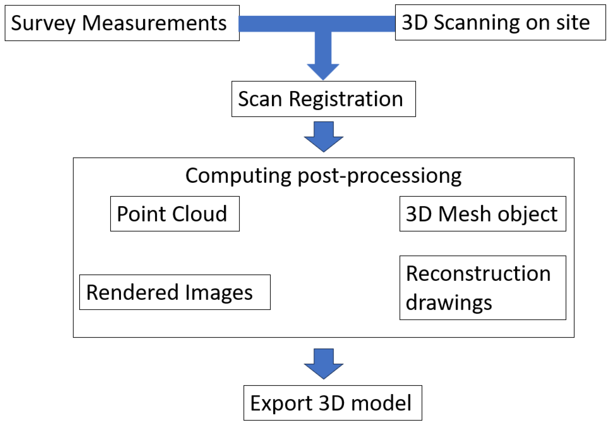
2.1. Scan and Point Cloud

Models of the Gothic church of Santa Maria Alemanna in Messina (Italy) were crafted, with the entire complex being surveyed by a laser scanner and 3D prints of various architectural sections produced using different technologies. The models were fabricated using a CNC milling machine and a 3D printer for MEX.
The subsequent list delineates the workflow of the scanning, reconstruction, and 3D model generation for AM fabrication (Figure 1):
  • Surveying, measuring, and setting up: This stage encompasses guidelines on planning and configuring a 3D laser scanner and the on-site targets, as well as setting up the basic configurations for the scanner.
  • On-site 3D laser scanning: This involves conducting an actual 3D laser scan of the building and site using the Leica HDS 4050 3D scanner (Leica, Wetzlar, Germany) and the corresponding targets.
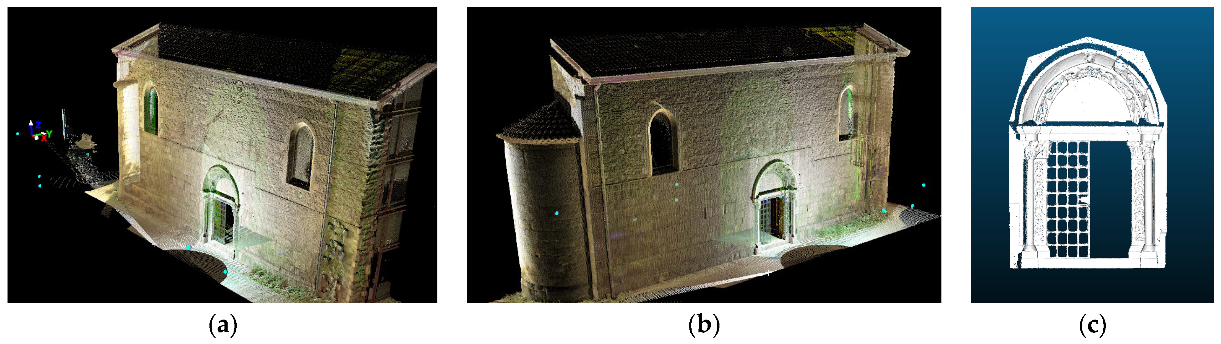
  • Scan registration in the database using Leica Geosystems Cyclone software: Here, the raw data are imported into the project database for registration via Cyclone software. The database produces point clouds from each site location and amalgamates them to form a 3D point cloud of the target building.
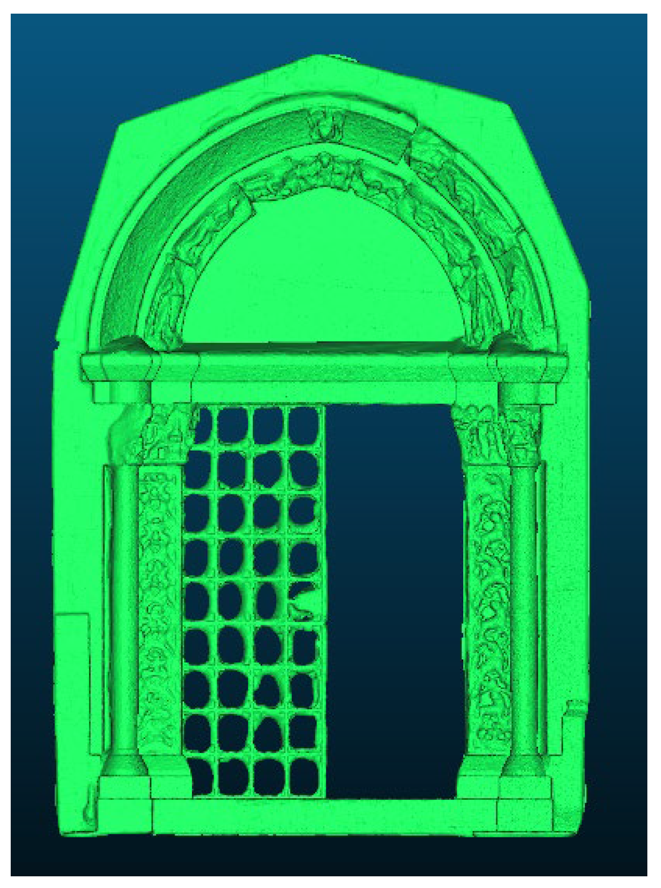
  • Reconstruction: This point cloud can be imported into 3D modelling software, in this instance, CloudCompare version 2.12 open source.
  • Exporting the reconstructed 3D model: By converting the point cloud into a mesh model (STL), a 3D digital model can be created. Additionally, a 3D physical model can be fabricated using a 3D printer.
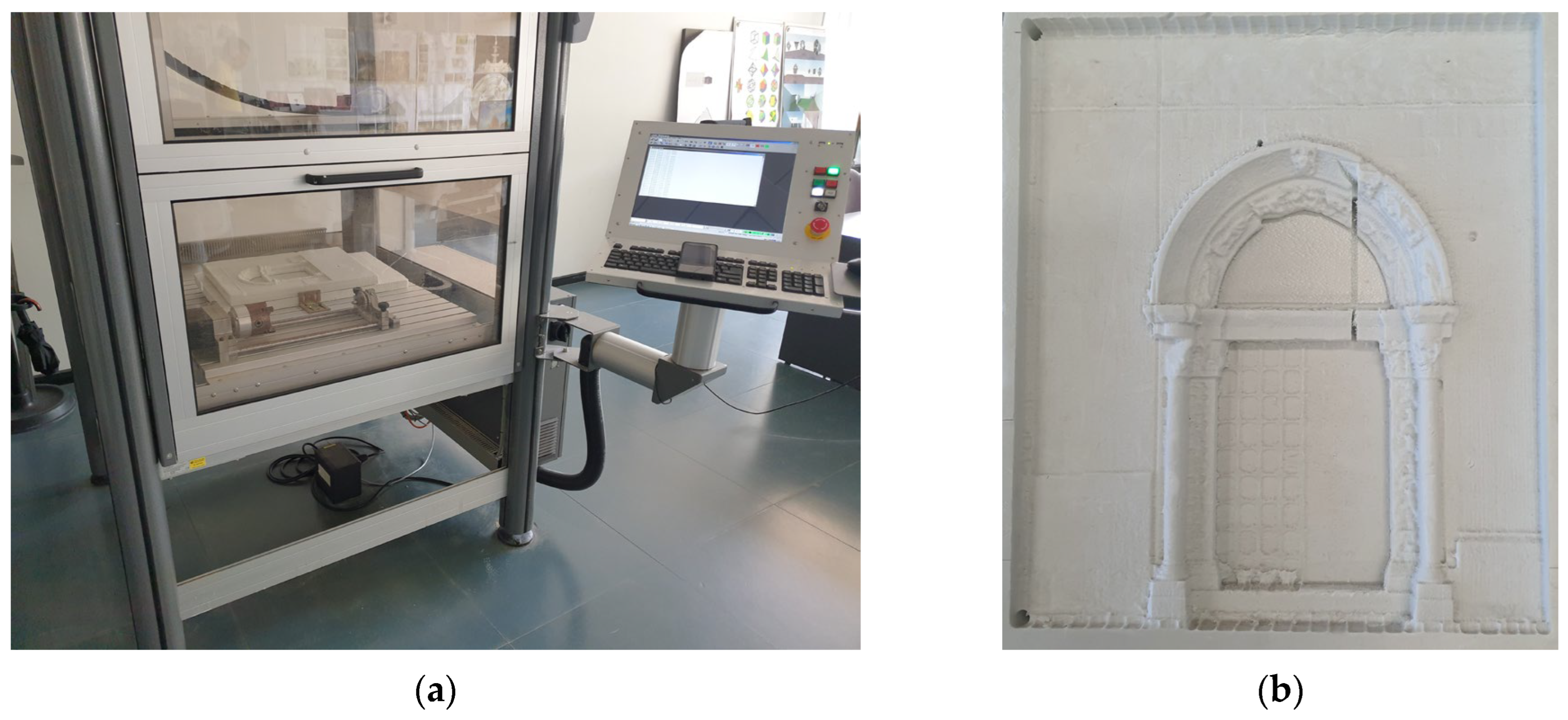
The Church of Santa Maria Alemanna, constructed in 1220, boasts a basilical structure (14.70 × 23.00 with a height, at the eaves line, of 10.30 m), comprising three naves, culminating in three semicircular apses facing east, with the central one being more expansive and featuring a splayed window. It stands as a prominent example of Swabian religious architecture in Sicily [6]. The church has experienced numerous restorations due to natural events (several earthquakes), war-inflicted damages, and degradation from human neglect. The current state, documented via 3D laser scanning in 2009, is the outcome of a restoration executed at the close of the previous century (1994), wherein integrations and reconstructions are evident. Notably, the west facade, which was demolished during the reconstruction of Messina after the 1908 earthquake, was reconstructed in glass with an iron framework, and the double-pitched tiled roof was mounted on wooden trusses. In an earlier restoration (1985), the side portal (the subject of the 3D print) was relocated, showcasing chisel work emblematic of the French medieval school [27]. The naves consist of stone block pillars accompanied by half-columns, resulting in a cruciform section, adorned with captivating capitals supporting pointed arches in the central nave and elevated arches in the side naves. The survey was executed with a Leica HDS 4050 3D laser scanner (Scan Station II). It is a time-of-flight device with high-speed pulses, equipped with a bi-axial compensator and a high-resolution integrated digital camera. It has an operational range of roughly 300 m for 90% reflective surfaces. It boasts a point positioning accuracy of ±3 mm at 150 m. The field of view for each scan spans 360° for the horizontal angle and 270° for the vertical angle. It emits a green laser (in class 3R), with a spot measuring 4 mm at a distance ranging between 0 and 50 m. It can achieve a maximum instantaneous speed of 4000 points/s. The work carried out after the initial project consisted of both internal (9) and external (8) stations. To record the various acquired point clouds together, high-reflectance targets were appropriately positioned. Specifically, at least three targets, not aligned with each other, common to one scan and the next, were required, the combination of whose equations allows the 3D rotation and translation between the reference systems in which the scans themselves are expressed with which they must be registered. In the case of the transition from inside to outside, and outside, due to limited space that did not allow for the positioning of common targets, it was necessary to resort to cloud-to-cloud overlap, with the recognition of at least seven homologous points. The density of the acquired points was controlled through the Leica Geosystems Cyclone 7 management software. The interface software with the 3D laser scanner creates the point cloud by coordinates (x, y, z) based on the time elapsed between the emitted wave and the returned/reflected wave. The envelope of the point cloud represents the surface of the object, hit by the polarized light beam, with a resolution of the scan matrix that, for the densification of some elements of the decorative apparatus, went up to 1 × 1 mm, for a total of approximately 19,640,000 acquired points. The overall cloud, recording the clouds obtained from the 17 stations, had a margin of error not exceeding 3 mm on the object of our survey (Figure 2). This cloud underwent cleaning and decimation operations (particularly, noise elimination), after which the 3D printing of the models was executed [28].

2.2. CNC Milling

The milling machine used to print the three models is the Isel Automation Flatcom 20, a CNC machine for cutting ductile materials, useful for creating physical scale models of architecture [29]. The maximum dimensions of the working environment are x = 600 mm, y = 550 mm, z = 250 mm. This is a 4-axis machine, as it also has a lathe that rotates the rough piece to be worked. The spindle, with a maximum rotation speed of 25,000 revolutions per minute, can manually mount tools with a diameter from 1 mm to 15 mm. The Flatcom 20 can mount spherical, cylindrical, and conical tools. The choice of tool size and type needs to be set in the software and it affects the outcome of the milled piece. The specific details of the milling machine are provided in Table 1.
The tool path was generated on a separate computer from the one managing the CNC milling machine’s operations. The 3D model (Figure 3) or 2D trace is exported in a .stl vector format, and the tool path is designed through the use of Abacus Mayka software, a CAM program managing CNCs up to 5 axes.
The model’s scale choice is fundamentally crucial, obviously influenced by the rough piece, which will dictate the choice of roughing and finishing paths. Once the various milling processes are set, the program simulates the machining in a 3D environment, allowing the designer to verify the conceived path’s validity; upon confirming the inputs, the tool path is exported and transferred to the computer managing the CNC. The milled piece from the CNC machine used is presented in Figure 4.

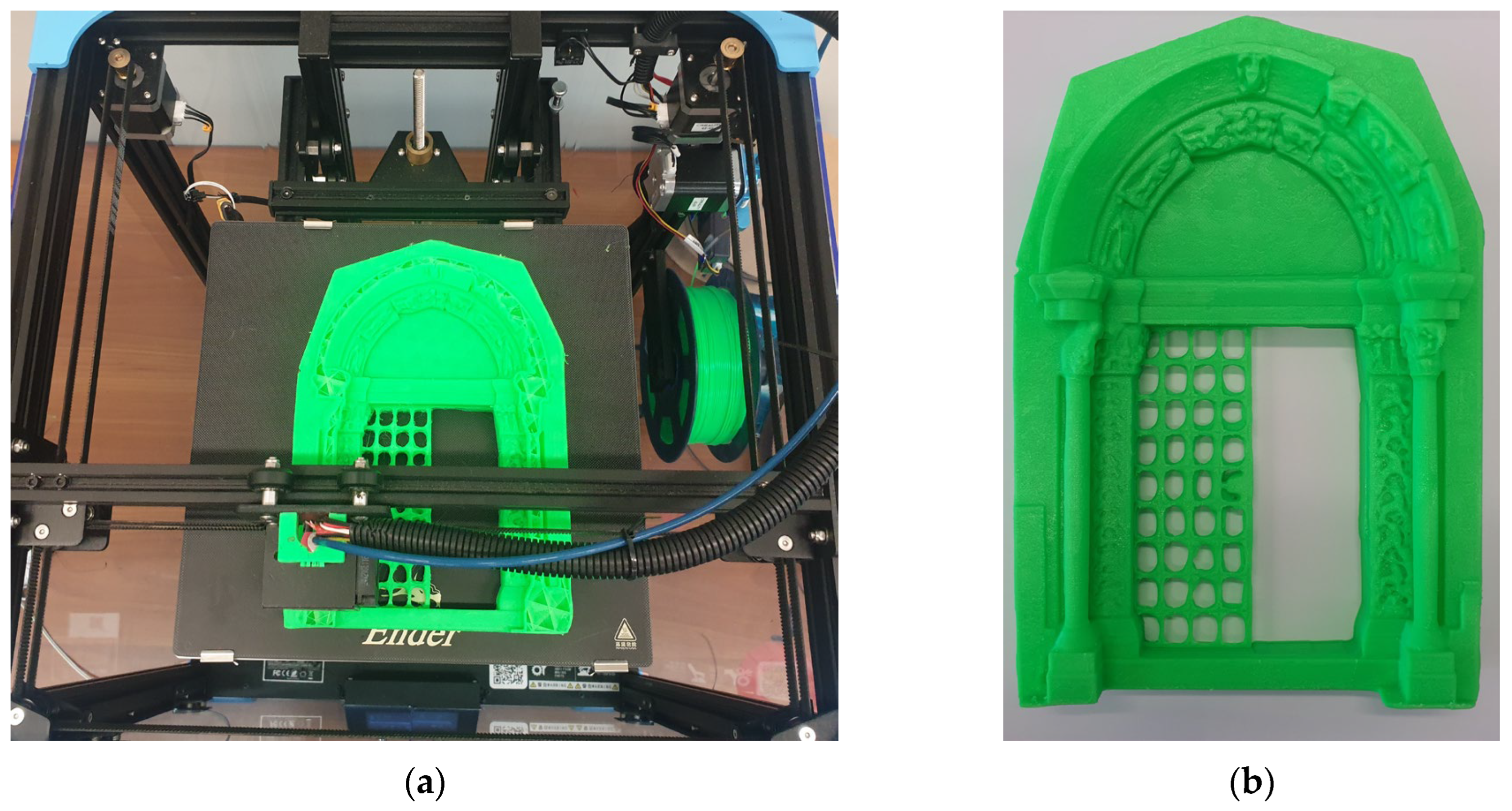
2.3. Material Extrusion

In this study, a three-dimensional model was created using the MEX technique (Figure 5), representing the architectural section of the Santa Maria Alemanna Church. The 3D printer employed to produce the object is the Creality Ender 6 (Creality 3D Technology Co., Ltd., Shenzhen, China) and the filament used is polylactic acid, known as PLA. The G-code file was created with UltiMaker’s Cura software version 5.2.1.
The parameters used by the 3D printer are shown in Table 2.
The Creality Ender 6 3D has a CoreXY type head movement. Its technical specifications are outlined below. It is capable of achieving a maximum precision of 0.1 mm with a minimum layer height of 0.1 mm and a maximum of 0.4 mm. This printer offers a substantial build volume of 250 × 250 × 400 mm and operates at a maximum print speed of 150 mm/s. The maximum temperatures supported are 260 °C for the nozzle and 100 °C for the heated bed. It is designed to use filament with a diameter of 1.75 mm. The overall dimensions of the structure are 495 × 495 × 650 mm, and it weighs 22 kg, making it a solid and reliable choice for a wide range of 3D printing applications.

2.4. Life Cycle Assessment

2.4.1. Goal and Scope Definition

The primary objective of this LCA is to investigate and contrast the environmental impact of fabricating a specific model using two different production technologies: a CNC machine and a rapid prototyping machine utilizing MEX technology. The functional unit for this analysis is the creation of one model. The overarching aim of the study is to offer credible quantitative data that can aid in making informed choices regarding the adoption of a more environmentally sustainable technology. To realize this, the study’s scope will focus on gauging and analyzing various facets of the product’s life cycle, encompassing electrical energy consumption, material utilization, and production duration.

2.4.2. Life Cycle Inventory

The LCA’s second phase, the life cycle inventory, entails gathering and examining data pertinent to the energy and materials expended throughout the product’s life cycle. The CNC machine boasts a peak power consumption of 4000 W and an average consumption of 2000 W, whilst the MEX machine’s top power consumption stands at 350 W, with an average consumption of 175 W. The production durations between the two technologies show marked differences, with the CNC machine taking 3 h to finalize the model, whereas the MEX machine necessitates a considerably lengthier span of 31 h. The materials chosen for each technology also differ significantly; the CNC machine utilizes two standard-sized polystyrene sheets (584 × 300 × 27 mm), whilst the MEX machine employs polylactic acid (PLA). In terms of the finished product’s weight, the CNC machine generates considerably more waste than the MEX technology, as the material discarded in chip form is much greater than the waste material in the guise of support. Another source of scrap is given by the fact that the solid to be milled is fed with the polystyrene panels which are then cut after milling. The aggregate mass amounts, both net and waste, are encapsulated in Table 3. Despite the different densities of the materials used in the two technologies, the final weight of the models produced, excluding waste material, is almost identical. This similarity is attributed to the fact that the model created with CNC technology has a 100% infill, while the model made with MEX technology employs only 10% infill. This disparity in infill levels yields models of equivalent final weight, thus allowing a just comparison in terms of material use efficiency.

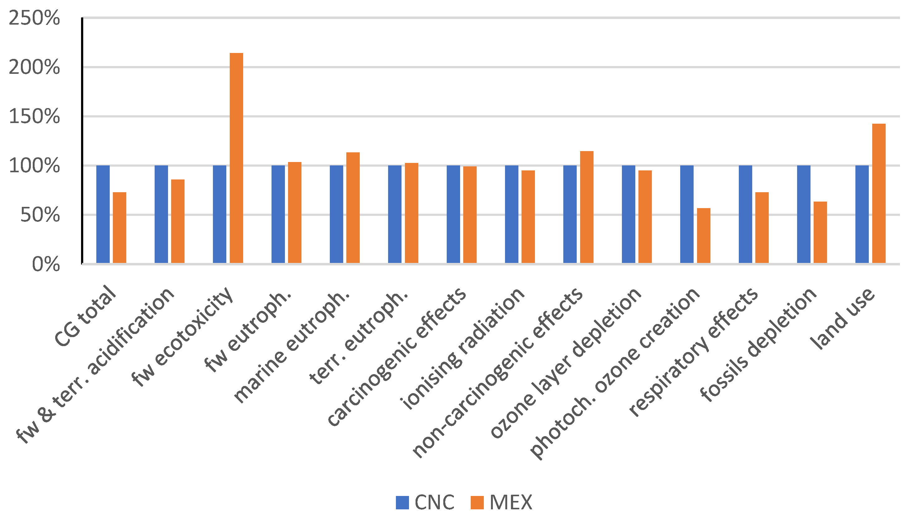
2.4.3. Life Cycle Impact Assessment

The final phase of the LCA is the Life Cycle Impact Assessment (LCIA), which involves interpreting the life cycle inventory results in terms of potential environmental impacts.
In this study, the International Reference Life Cycle Data System (ILCD) method [30], updated in 2018, was applied, using the midpoint approach [31]. This approach assesses the impact across four key areas: Climate Change (CC) [32], Human Health (HH) [33], Resource Depletion (RD) [34], and Ecosystem Quality (EQ) [35]. The methodology facilitates a comprehensive understanding of the environmental impacts associated with each technology, enabling a precise comparison based on concrete data.

3. Results and Discussion

The Life Cycle Assessment outcomes offer a thorough comparison of the CNC and MEX technologies across various environmental impact categories. The precise details of these results are detailed in Table 4. This information is also illustrated in Figure 6, where a percentage comparison is conducted, establishing the impact of the CNC as a baseline of 100%.
Table 5 presents the Life Cycle Impact Analysis (LCIA) in accordance with the ILCD 2018 guidelines, comparing the environmental impact of 1 kg of polystyrene with that of 1 kg of PLA. In this comparison, only the impact categories exhibiting the most substantial differences are shown, as these were of greater interest for the study.
The MEX technology has a lower carbon footprint, with total climate change impact amounting to 2.98 kg CO2-Eq compared to CNC’s 4.09 kg CO2-Eq (−27% less than CNC carbon emissions).
This trend of MEX technology’s lesser environmental impact is also observed in the categories of freshwater and terrestrial acidification, as well as ionizing radiation. For carcinogenic effects, ozone layer depletion, and non-carcinogenic effects, the results are quite close, but with a marginally lesser impact from the MEX technology.
In contrast, the freshwater ecotoxicity is higher with the MEX technology, standing at 3.38 CTU compared to CNC’s 1.58 CTU. Similarly, categories such as freshwater, marine, and terrestrial eutrophication are marginally higher for MEX technology.
Regarding resource usage, MEX technology uses fewer fossil resources, as reflected by a measurement of 46.4 MJ compared to the CNC’s 73.3 MJ. However, MEX technology demonstrates a higher impact in terms of land use. The reasons for these observed distinctions can largely be attributed to the fundamental differences in the materials utilized in this case study. For the MEX technology, PLA, a product derived from renewable resources such as corn and sugarcane, was used, while in contrast, for the CNC technology, a reliance was placed on petrochemical-based materials.
The heightened freshwater ecotoxicity and eutrophication linked with MEX technology can be associated with the agricultural practices necessary to produce the biomass resources for PLA. The cultivation of these crops often requires the application of fertilizers, rich in compounds such as nitrates and phosphates. These compounds can find their way into surrounding water bodies, leading to increased levels of ecotoxicity and contributing to eutrophication, a process where over-enrichment of bodies of water can disrupt and damage aquatic ecosystems.
However, this shift towards renewable resources has a larger impact in terms of land use. The cultivation of crops like corn and sugarcane for PLA production requires considerable quantities of agricultural land [36]. This factor contributes to the increased land use impact associated with MEX technology, highlighting a key trade-off between reduced fossil resource usage and increased land use.
The “Human Health (Photochemical Ozone Creation)” category pertains to the possible formation of tropospheric ozone, a phenomenon driven by the photochemical oxidation of Volatile Organic Compounds (VOCs) and carbon monoxide (CO), under the influence of nitrogen oxides (NOx) and sunlight. The notable differences between the two technologies examined in this category can be traced back to the choice of materials used, as displayed in Table 5. Additionally, the MEX technology consumes less energy than its counterpart, leading to a reduction in the emissions associated with energy production and thus diminishing the potential for photochemical ozone creation.
The reduced impact in the “Human Health (Respiratory Effects, Inorganics)” category for the MEX technology is directly attributable to its lower energy consumption. The generation and utilization of energy represent a significant source of air pollution, including inorganic pollutants that have detrimental effects on respiratory health. The decreased energy consumption of MEX technology results in fewer emissions of such pollutants, leading to a diminished impact in this category.
In the “Resources Fossils” category, which concerns the consumption of fossil resources such as coal, oil, and natural gas, MEX technology, due to its lower power demand compared to CNC, uses fewer of these resources. Additionally, the choice of material used plays a role in this category. The manufacture of polystyrene, used in CNC machining, is a petroleum-based process. In contrast, the creation of PLA, which is used in MEX, is reliant on renewable resources such as cornstarch or sugarcane. This contributes to a decrease in the fossil resource usage associated with material production.
In terms of scrap production or waste material during the manufacturing process, there is a marked difference between the two technologies. The CNC machine generated a considerably larger amount of scrap, weighing 160 g for a finished model of 360 g. This accounts for roughly 44% of the total weight of the finished product. Conversely, the MEX technology produced a significantly lower scrap weight of 7 g for a 208 g model, which is merely 3% of the total product weight. This discrepancy is significant in terms of waste management and resource efficiency, where lower waste production optimizes the use of raw materials, contributing to overall process sustainability.
Taking all these findings into account, MEX technology generally demonstrates lower environmental impact across most categories, and significantly lower waste production, indicating a more sustainable choice. However, it is crucial to remember that the ultimate decision should consider other factors, such as production time, product quality, cost, and specific requirements of the product.
Even though, in the case study, comparable products were produced using similar parameters, the flexibility of machine use is undeniably different. The CNC machine, for instance, boasts a considerably larger working volume compared to the MEX, offering greater flexibility in terms of the size of the piece that can be worked on. On the other hand, the MEX stands out for its significantly lower initial investment costs. From the perspective of workable materials, the two machines have distinctive features; while the CNC is versatile in processing a range of materials such as wood and aluminum, the MEX specializes in working with various polymers, including ABS, Nylon, and many others. These differences underscore the importance of the considered choice of machine based on the specific needs of the project.
In terms of accuracy, the CNC’s motion motors are of the same order of magnitude as those of the MEX (hundredths of a mm). As regards the final machining precision, the result is strongly dependent on the installed tool, for the CNC, and on the nozzle, for the MEX. In order to make a comparison, the piece produced was made with the same manufacturing tolerances of 0.4 mm.

4. Conclusions

The current research sheds light on the varied environmental impacts of CNC and MEX technologies, both of which are extensively utilized in the fabrication of architectural models. This provides invaluable insights into their comparative sustainability. The data suggest that MEX technology generally yields lower environmental impacts across most categories compared to CNC technology, with significantly lower scrap production. Such insights could hold significant implications for sectors dependent on these technologies, guiding more environmentally conscious decisions in production methodologies.
However, it is essential to recognize that the choice of technology should not be determined solely by environmental considerations. Other factors, such as production duration, product quality, cost, and specific product requirements, are equally pivotal. For instance, while MEX technology demonstrates a reduced environmental footprint in areas like climate change and resource consumption, its impacts in certain areas, such as freshwater ecotoxicity and land occupation, are relatively higher. Therefore, context-specific evaluation of these technologies is crucial.
Regarding the broader applications of these technologies, 3D printing introduces novel prospects in domains like cultural heritage and museum studies. It not only facilitates the tangible replication of invaluable artifacts, enhancing the accessibility of cultural heritage, but also fosters a more immersive and captivating interaction with these items. The potential of these technologies to make cultural and artistic heritage more accessible is vast, and the importance of developing these technologies sustainably is evident.
Future investigations should persist in exploring and refining the environmental efficacy of these technologies. Comparative analyses akin to this one are vital for discerning their relative impacts, and comprehensive life cycle evaluations will be central to realizing a more sustainable future. Moreover, future studies could also delve into the other aspects of these technologies, such as the socio-economic and cultural implications of making historical artifacts more accessible.
In conclusion, while the findings favor MEX technology in terms of its environmental impact and waste production, a holistic approach considering a range of factors should inform technology selection. The exciting potential of these technologies in transforming cultural heritage engagement reaffirms the need for sustainable development in this field.

Author Contributions

Conceptualization, F.C. and A.A.; methodology, F.S. (Fabio Salmeri) and F.C.; software, F.S. (Fabio Salmeri); validation, F.S. (Fabio Salmeri), A.A. and M.R.; investigation, F.S. (Felice Sfravara); data curation, F.S. (Felice Sfravara); writing—original draft preparation, M.R. and F.S. (Fabio Salmeri); writing—review and editing, F.C. All authors have read and agreed to the published version of the manuscript.

Funding

This research received no external funding.

Institutional Review Board Statement

Not applicable.

Informed Consent Statement

Not applicable.

Data Availability Statement

The data presented are available on this paper.

Conflicts of Interest

The authors declare no conflict of interest.

References

  1. Bacon, B.; Khatiri, A.; Palmer, J.; Freeth, T.; Pettitt, P.; Kentridge, R. An Upper Palaeolithic Proto-writing System and Phenological Calendar. Camb. Archaeol. J. 2023, 33, 371–389. [Google Scholar] [CrossRef]
  2. Pacciani, R. I Modelli Lignei Nella Progettazione Rinascimentale; C.I.P.I.A.: Bologna, Italy, 1988; ISBN 88-289-0257-4. [Google Scholar]
  3. Ferretti, E. All’ombra di Leon Battista Alberti e Michelangelo: Modelli lignei e cultura architettonica fra Cosimo Bartoli, Vincenzio Borghini e Giorgio Vasari. Kritiké 2020, 1, 83–114. [Google Scholar]
  4. Pignatelli, F.; Percoco, G. An application- and market-oriented review on large format additive manufacturing, focusing on polymer pellet-based 3D printing. Prog. Addit. Manuf. 2022, 7, 1363–1377. [Google Scholar] [CrossRef]
  5. Valiente, E.E.; D’amico, F.C.; Martín, F.d.C. Architecture and Archeology. Virtual Reconstruction of Ipi’s Tomb TT315 in Deir-el-Bahari, Theban, Egypt. In Digital Restoration and Virtual Reconstructions; Springer: Berlin/Heidelberg, Germany, 2023; pp. 169–183. [Google Scholar] [CrossRef]
  6. Basile, F. Le chiese del Duecento a Messina. In Quaderno dell’Istituto Dipartimentale di Architettura e Urbanistica dell’Università di Catania; Università di Catania: Catania, Italy, 1971. [Google Scholar]
  7. Ronco, F. Prototypes to Increase Museum Experience and Accessibility. Palazzo Mazzonis’ Atrium in Turin: The Work in Progress. In Digital Heritage. Progress in Cultural Heritage: Documentation, Preservation, and Protection; Springer: Berlin/Heidelberg, Germany, 2021; pp. 605–613. [Google Scholar] [CrossRef]
  8. Bertola, G. BIM and Rapid Prototyping for Architectural Archive Heritage. In Digital Heritage. Progress in Cultural Heritage: Documentation, Preservation, and Protection; Springer: Berlin/Heidelberg, Germany, 2021; pp. 614–623. [Google Scholar] [CrossRef]
  9. Wong, S.Y.; Chuah, J.H.; Yap, H.J. Technical data-driven tool condition monitoring challenges for CNC milling: A review. Int. J. Adv. Manuf. Technol. 2020, 107, 4837–4857. [Google Scholar] [CrossRef]
  10. Solomon, I.J.; Sevvel, P.; Gunasekaran, J. A review on the various processing parameters in FDM. Mater. Today Proc. 2021, 37, 509–514. [Google Scholar] [CrossRef]
  11. D’Andrea, D.; Risitano, G.; Raffaele, M.; Cucinotta, F.; Santonocito, D. Damage assessment of different FDM-processed materials adopting Infrared Thermography. Fract. Struct. Integr. 2022, 16, 75–90. [Google Scholar] [CrossRef]
  12. ISO 14040:2021; Environmental Management—Life Cycle Assessment—Principles and Framework. ISO: Geneva, Switzerland, 2021.
  13. ISO 14044:2021; Environmental Management—Life Cycle Assessment—Requirements and Guidelines. ISO: Geneva, Switzerland, 2021.
  14. Finkbeiner, M. The International Standards as the Constitution of Life Cycle Assessment: The ISO 14040 Series and its Offspring. In Background and Future Prospects in Life Cycle Assessment; Springer: Berlin/Heidelberg, Germany, 2014; pp. 85–106. [Google Scholar] [CrossRef]
  15. ISO 14025:2010; Environmental Labels and Declarations—Type III Environmental Declarations—Principles and Procedures. ISO: Geneva, Switzerland, 2010.
  16. Pfähler, K.; Morar, D.; Kemper, H.-G. Exploring Application Fields of Additive Manufacturing Along the Product Life Cycle. Procedia CIRP 2019, 81, 151–156. [Google Scholar] [CrossRef]
  17. Ma, J.; Harstvedt, J.D.; Dunaway, D.; Bian, L.; Jaradat, R. An exploratory investigation of Additively Manufactured Product life cycle sustainability assessment. J. Clean. Prod. 2018, 192, 55–70. [Google Scholar] [CrossRef]
  18. Reis, R.C.; Kokare, S.; Oliveira, J.; Matias, J.C.; Godina, R. Life cycle assessment of metal products: A comparison between wire arc additive manufacturing and CNC milling. Adv. Ind. Manuf. Eng. 2023, 6, 100117. [Google Scholar] [CrossRef]
  19. Di Bella, G.; Alderucci, T.; Salmeri, F.; Cucinotta, F. Integrating the sustainability aspects into the risk analysis for the manufacturing of dissimilar aluminium/steel friction stir welded single lap joints used in marine applications through a Life Cycle Assessment. Sustain. Futur. 2022, 4, 100101. [Google Scholar] [CrossRef]
  20. Cucinotta, F.; Raffaele, M.; Salmeri, F. A Well-to-Wheel Comparative Life Cycle Assessment Between Full Electric and Traditional Petrol Engines in the European Context. In Proceedings of the International Joint Conference on Mechanics, Design Engineering & Advanced Manufacturing, Aix-en-Provence, France, 2–4 June 2020; pp. 188–193. [Google Scholar] [CrossRef]
  21. Gata, K.M.; Valiente, E.E. The use of digital tools for the preservation of architectural, artistic and cultural heritage, through three-dimensional scanning and digital manufacturing. ISPRS—Int. Arch. Photogramm. Remote Sens. Spat. Inf. Sci. 2019, 42, 501–506. [Google Scholar] [CrossRef]
  22. Scopigno, R.; Cignoni, P.O.; Pietroni, N.O.; Callieri, M.O.; Dellepiane, M. Digital Fabrication Technologies for Cultural Heritage (STAR). In Proceedings of the EUROGRAPHICS Workshop on Graphics and Cultural Heritage, Darmstadt, Germany, 6–8 October 2014. [Google Scholar] [CrossRef]
  23. Jesus, M.; Guimarães, A.S.; Rangel, B.; Alves, J.L. The potential of 3D printing in building pathology: Rehabilitation of cultural heritage. Int. J. Build. Pathol. Adapt. 2023, 41, 647–674. [Google Scholar] [CrossRef]
  24. EN 15898:2011; Conservation of Cultural Property—Main General Terms and Definitions. NSAI: Dublin, Ireland, 2011.
  25. Champion, E.; Rahaman, H. 3D Digital Heritage Models as Sustainable Scholarly Resources. Sustainability 2019, 11, 2425. [Google Scholar] [CrossRef]
  26. Vilceanu, B.; Sorin, H.; Oana, G. 3D models for a sustainable development of cultural heritage. In Proceedings of the International U.A.B.—B.EN.A. Conference Environmental Engineering and Sustainable Development, Alba Iulia, Romania, 28–30 May 2015. [Google Scholar]
  27. Molonia, G. Messina. Storia e Civiltà; GBM: Messina, Italy, 1997. [Google Scholar]
  28. Al-Mistarehi, B.W.; Alomari, A.H.; Mijwil, M.M.; Khedaywi, T.S.; Ayasrah, M. Model Structure from Laser Scanner Point Clouds. In Proceedings of the International Conference on Frontiers in Computing and Systems, Shillong, India, 29 September–1 October 2021; pp. 181–190. [Google Scholar] [CrossRef]
  29. Bizzarri, M.; Bartoň, M. Manufacturing of Screw Rotors Via 5-axis Double-Flank CNC Machining. Comput. Des. 2021, 132, 102960. [Google Scholar] [CrossRef]
  30. EC-JRC. International Reference Life Cycle Data System (ILCD) Handbook—General Guide for Life Cycle Assessment—Detailed Guidance, 1st ed.; Publications Office of the European Union: Luxembourg, 2010. [Google Scholar] [CrossRef]
  31. Ling-Chin, J.; Roskilly, A.P. A comparative life cycle assessment of marine power systems. Energy Convers. Manag. 2016, 127, 477–493. [Google Scholar] [CrossRef]
  32. Griggs, D.J.; Noguer, M. Climate change 2001: The scientific basis. Contribution of Working Group I to the Third Assessment Report of the Intergovernmental Panel on Climate Change. Weather 2002, 57, 267–269. [Google Scholar] [CrossRef]
  33. Posch, M.; Seppälä, J.; Hettelingh, J.-P.; Johansson, M.; Margni, M.; Jolliet, O. The role of atmospheric dispersion models and ecosystem sensitivity in the determination of characterisation factors for acidifying and eutrophying emissions in LCIA. Int. J. Life Cycle Assess. 2008, 13, 477–486. [Google Scholar] [CrossRef]
  34. Goedkoop, M.; Heijungs, R.; Huijbregts, M.; De Schryver, A. ReCiPE 2008: A Life Cycle Impact Assessment Method which Comprises Harmonised Category Indicators at the Midpoint and the Endpoint Level; Ministerie van VROM: The Hague, The Netherlands, 2009. [Google Scholar]
  35. Henderson, A.D.; Hauschild, M.Z.; van de Meent, D.; Huijbregts, M.A.J.; Larsen, H.F.; Margni, M.; McKone, T.E.; Payet, J.; Rosenbaum, R.K.; Jolliet, O. USEtox fate and ecotoxicity factors for comparative assessment of toxic emissions in life cycle analysis: Sensitivity to key chemical properties. Int. J. Life Cycle Assess. 2011, 16, 701–709. [Google Scholar] [CrossRef]
  36. Morão, A.; de Bie, F. Life Cycle Impact Assessment of Polylactic Acid (PLA) Produced from Sugarcane in Thailand. J. Polym. Environ. 2019, 27, 2523–2539. [Google Scholar] [CrossRef]
Figure 1. Workflow.
Figure 1. Workflow.
Sustainability 15 13487 g001
Figure 2. In (a,b), two perspectives of the church Santa Maria Alemanna in Messina are represented through the point cloud generated by the laser scanner. (c) depicts the point cloud of the specific architectural portion under study.
Sustainability 15 13487 g002
Figure 3. The 3D model in a .stl vector format.
Sustainability 15 13487 g003
Figure 4. In the image (a), the CNC milling machine used in the construction process of the architectural portion of the Church of Santa Maria Alemanna (b).
Sustainability 15 13487 g004
Figure 5. The architectural portion of the Church of Santa Maria Alemanna (b), created using the MEX approach (a).
Sustainability 15 13487 g005
Figure 6. Percentage comparison between the two configurations (CNC base 100).
Sustainability 15 13487 g006
Table 1. Technical data—Isel Automation Flatcom 20.
Isel Automation Flatcom 20—Technical Data
Cabinet Size1200 mm (800 mm) × 600 mm × 250 mm
Protection categoryIP 44
Ambient temperature0° C up to +40 °C
Storage temperature−25° C up to +70 °C
Rel. humidity of the airMax 95%
Mains voltage250 V
Max nominal input current16 A
Mains frequency50 Hz
Table 2. Printing process parameters.
Nozzle
Diameter
Nozzle
Temperature
Bed
Temperature
Printing
Speed
Layer Height Printing
Infill
0.4 mm200 °C60 °C135 mm s−10.12 mm10%
Table 3. Comparison of the weights of models made with the two technologies, with and without scraps.
TechnologyModel’s Weight [g]Scraps Weight [g]Total Weight [g]
CNC200160360
MEX2017208
Table 4. Impact assessment according to the ILCD 2018 method.
IndicatorCNCMEXUnit
climate change (climate change biogenic)4.93 × 10−23.87 × 10−2kg CO2-Eq
climate change (climate change fossil)4.042.93kg CO2-Eq
climate change (climate change land use and land use change)8.07 × 10−45.26 × 10−3kg CO2-Eq
climate change (climate change total)4.09 2.98kg CO2-Eq
ecosystem quality (freshwater and terrestrial acidification)1.98 × 10−21.70 × 10−2mol H+-Eq
ecosystem quality (freshwater ecotoxicity)1.583.38CTU
ecosystem quality (freshwater eutrophication)8.77 × 10−49.08 × 10−4kg P-Eq
ecosystem quality (marine eutrophication)2.95 × 10−33.34 × 10−3kg N-Eq
ecosystem quality (terrestrial eutrophication)3.61 × 10−23.70 × 10−2mol N-Eq
human health (carcinogenic effects)4.06 × 10−84.02 × 10−8CTUh
human health (ionising radiation)3.51 × 10−13.33 × 10−1kg U235-Eq
human health (non-carcinogenic effects)2.60 × 10−72.98 × 10−7CTUh
human health (ozone layer depletion)3.83 × 10−73.64 × 10−7kg CFC-11-Eq
human health (photochemical ozone creation)1.37 × 10−27.78 × 10−3kg NMVOC-Eq
human health (respiratory effects, inorganics)1.13 × 10−78.19 × 10−8disease incidence
resources (fossils)7.33 × 104.64 × 10MJ
resources (land use)2.70 × 103.84 × 10points
resources (minerals and metals)1.33 × 10−81.03 × 10−9kg Sb-Eq
Table 5. ILCD 2018 LCIA—comparison between 1 kg of polystyrene and 1 kg of PLA.
IndicatorPolystyrenePLAUnit
climate change (climate change total)4.27 3.21 kg CO2-Eq
ecosystem quality (freshwater and terrestrial acidification)1.68 × 10−22.21 × 10−2mol H+-Eq
ecosystem quality (freshwater ecotoxicity)2.02 1.26 × 10CTU
ecosystem quality (freshwater eutrophication)4.37 × 10−41.24 × 10−3kg P-Eq
ecosystem quality (marine eutrophication)2.82 × 10−37.66 × 10−3kg N-Eq
ecosystem quality (terrestrial eutrophication)2.98 × 10−26.76 × 10−2mol N-Eq
human health (photochemical ozone creation)2.18 × 10−21.20 × 10−2kg NMVOC-Eq
human health (respiratory effects, inorganics)1.63 × 10−71.59 × 10−7disease incidence
resources (fossils)8.90 × 104.38 × 10MJ
resources (land use)8.48 8.06 × 10points
Disclaimer/Publisher’s Note: The statements, opinions and data contained in all publications are solely those of the individual author(s) and contributor(s) and not of MDPI and/or the editor(s). MDPI and/or the editor(s) disclaim responsibility for any injury to people or property resulting from any ideas, methods, instructions or products referred to in the content.

