Article

Study on Splitting Damage Characteristics of a Rock–Shotcrete Interface Subjected to Corrosive Water

1
College of Geology and Environment, Xi’an University of Science and Technology, Xi’an 710054, China
2
China Railway 20th Bureau Group Co., Ltd., Xi’an 710016, China
*
Authors to whom correspondence should be addressed.
Sustainability 2022, 14(9), 4987; https://doi.org/10.3390/su14094987
Submission received: 20 March 2022 / Revised: 2 April 2022 / Accepted: 7 April 2022 / Published: 21 April 2022

Abstract

:
Splitting tensile real time acoustic emission tests were carried out on rock–shotcrete binary specimens under the action of different corrosive waters in different periods. The effect of corrosion on the damage process of the binary interface was studied from a mesoscopic point of view. The results showed that the physical and chemical properties of the binary specimens were changed due to corrosion, resulting in a decrease in the tensile strength. Moreover, the corrosion effect of the acid solution is relatively strong throughout the whole corrosion cycle. It can be seen that the acoustic emission signal can reflect the interface microcrack propagation and inoculation process from the stress–strain curve, the ringing count, and the cumulative energy correspondence. Furthermore, the peak point of each parameter decreases with deepening the corrosion degree in different corrosive environments. The same-step variation in numerical value can provide certain early warning information. The application of acoustic emission B value indicates that the failure mode of the interface of the binary body develops from the failure of large internal cracks to the failure of continuous small cracks as the corrosion intensifies. The damage model established based on acoustic emission cumulative ringing count can better characterize the coupling relationship between corrosion-load-damage of the binary.

1. Introduction

With the continuous deepening and expansion of underground space and tunnel excavation, the durability problem of geological engineering structures has become increasingly prominent. Geological engineering construction in China is often in groundwater rich mountainous areas. Under certain conditions, water bodies are rich in many different types of soluble salts, which make the geological environment different. Following geological movement, the groundwater level is always both high and low, and the flow rate is constantly changing; thus, the corrosion effect of scouring on the engineering body becomes apparent. For tunnel engineering, the bonding performance between shotcrete and rock during lining construction has a weak field effect due to its interface [1]. It is vulnerable to material properties, interface properties, and external environmental impact [2]. A rock–shotcrete structure is forced to serve in an acidic and alkaline environment for a long time, and its mechanical properties inevitably deteriorate. The long term gradual process from damage degradation to instability and failure has a pronounced effect over time, significantly increasing engineering geological disasters’ concealment and destructiveness. Therefore, it is of great practical significance to study the damage evolution law and mechanism of the rock–shotcrete binary structure under the action of corrosive water for tunnel engineering disaster warning.
Conventional detection technology has been gradually abandoned in engineering, due to unrecoverable damage to structures. Moreover, emerging nondestructive testing technology has become mainstream. Acoustic emission technology has been widely used since its development, due to its unique advantages. It can obtain physical properties related to the tested material without damaging the structure and chemical properties of the material itself [3]. The material propagates the acoustic emission signal to the outside world under the condition of external force load. The continuity and real time acoustic emission signals can fully record damaged parts’ spatial and temporal effects. At present, many scholars have used acoustic emission technology to study various problems in rock mechanics and achieved a lot, such as Li Xiaoning et al. [4], and used acoustic emission technology to explore the mesoloss evolution characteristics of red bed soft rock under acidic environment erosion. It has been found that an acid solution was mainly dissolved in red bed soft rock, and, with the decrease of pH, the degree of chemical corrosion was more significant, and the distribution of dissolved pores was wider. Liu et al. [5] carried out a uniaxial acoustic emission test of water–rock interactions. They found that water had an inhibitory effect on the rock’s mechanical properties and acoustic emission activities. By studying the damage process of granite, Zhang et al. [6] found that acoustic emission energy, amplitude, and emission b value can better characterize the essential characteristics of rock fracture. Zhang et al. [7] combined acoustic emission characteristic parameters and stress–strain curves to analyze the shear performance of concrete before and after corrosion. It was concluded that the specimen’s shear strength and peak acoustic emission parameters are significantly reduced with the extension of corrosion time. Sun et al. [8] studied the damage mechanical behavior of a rock–shotcrete integrated two-media structure under dry and saturated conditions and divided the acoustic emission events into four stages: compaction, elasticity, plasticity, and failure. Su et al. [9] took a rock–shotcrete integrated two media structure as a physical model. They carried out a uniaxial acoustic emission test to confirm that the time when the concrete crack finally extended to the rock through the whole interface and accelerated the damage to relative instability and failure, was the point of a sudden increase in AE parameters. Liu et al. [10] conducted a Brazilian splitting acoustic emission test on sandstone under different freeze–thaw cycles. The damage variables can better reflect tensile damage characteristics and the whole evolution process of freeze–thaw sandstone.
In summary, the variation of acoustic emission parameters in the loading process of rock materials has a positive role in promoting the understanding of the damage evolution characteristics of rock materials. However, most studies mainly concentrate on single or composite materials’ uniaxial and triaxial compression tests [11,12,13,14,15,16,17,18]. Most of the splitting damage characteristics of rock–shotcrete binary structures under corrosive water have not been directly considered, so it is necessary to research the damage model of rock–shotcrete interface bonding performance in the corrosive area. In this paper, the rock–shotcrete binary is taken as the object, and an indoor long term accelerated corrosion is carried out. At the same time, the splitting tensile test is carried out on the interface with acoustic emission technology, to study the damage characteristics of interface bonding performance. The damage model established based on the acoustic emission characteristic parameters can provide a good reference value for the related work of tunnel lining in corrosion areas.

2. Test Overview

2.1. Sample Preparation

The rock sample was obtained from a tunnel under construction at long-zhang expressway in Gansu Province, China, with dimensions of 100 × 100 × 50 mm. The composition and mass fraction of the rock, identified by X-ray diffraction, are shown in Table 1. To ensure the reduction of later test errors, the test rock samples were selected from the same rock mass in the same stratum level inside the tunnel, and their geological, physical, and mechanical properties were uniform. The concrete part consisted of C25 concrete, and the mix proportion is shown in Table 2. According to the requirements of rock mechanics specifications, the 100 × 100 × 100 mm triple test mold was used for concrete perfusion. After the perfusion was completed, the specimen was placed on the vibration table. To ensure the compactness of the concrete, the vibration time was set to 30 s. After the vibration was completed, the mold was removed after standing indoors for 24 h. Finally, the samples were removed after 28 days of maintenance in a standard nursing room at a room temperature of 20 ± 2 °C and humidity of not less than 95%. The rock–shotcrete binary specimen is shown in Figure 1, and the mechanical parameters of the material are shown in Table 3.

2.2. Test Equipment

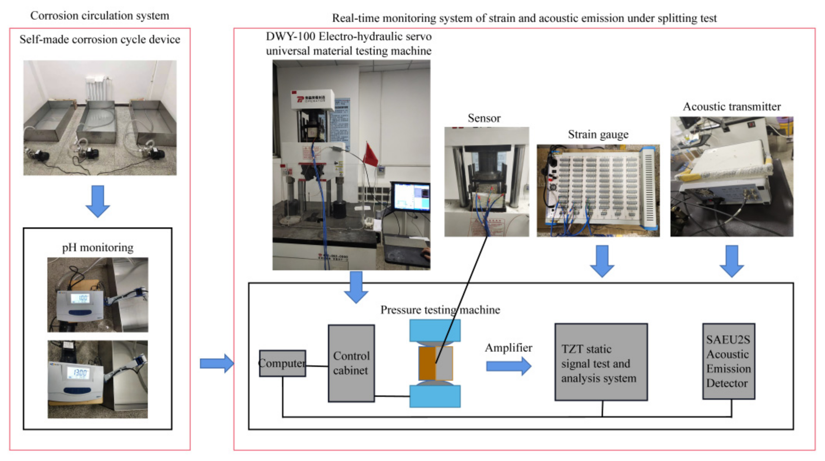
A self-made circulating corrosion system carried out a self-circulating corrosion test of the rock–shotcrete binary under corrosive water. It mainly depends on pump power to circulate the internal solution, which can ensure that the rock–shotcrete interface is entirely eroded so that the internal seepage flow of the specimen changes with the change of the specimen. This solves the acceleration effect that the previous indoor test does not create and is closer to the actual situation. The loading device of the sample was a DWY-100 electrohydraulic servo universal material testing machine of China Railway Jianke Testing Co., Ltd. (Shanghai, China). The maximum test force of the machine was 100 kN, and the displacement resolution was 0.01 mm. The strain device adopted the TZT3826E static signal test and analysis system; the maximum sampling frequency was 5 Hz, the full path was 60, the strain measurement range was ±100,000 με, and the system indication error was less than 0.5% ± 3 με. The acoustic emission device adopted the SAEU2S integrated acoustic emission system, mainly composed of a probe, host, and computer. The maximum acquisition frequency of acoustic emission was 10 MHz, and the acquisition accuracy was 16 bit, which can provide a maximum continuous data effective transmission rate of 30 MB/s. The sensitivity of the acoustic emission system is mainly controlled by setting the threshold value. The higher the threshold value, the lower the sensitivity and the more significant the external interference. According to the relevant literature and the noise level of the actual test environment, the threshold value of 40 dB was selected. The test device is shown in Figure 2.

2.3. Test Scheme

Considering the time effect of corrosive water erosion on the surrounding rock spray layer in the tunnel, the structure often needs decades or even hundreds of years from initial installation to loss of function. The corrosive water environment is complex and diverse; an H2SO4 solution with pH = 1 and NaOH solution with pH = 13 were configured for indoor accelerated corrosion tests. Furthermore, distilled water with pH = 7 was set to compare the corrosion tests under two different corrosive water environments. Four groups of specimens (three in each group) were immersed in each solution, and the indoor accelerated corrosion test was carried out every 30 days for a corrosion cycle. The specimens were weighed, put into a 105 °C oven for 24 h, and then weighed again after each stage of corrosion. A splitting tensile real time acoustic emission test was carried out. The specimen was loaded with stress controls, and the loading rate was 0.3 MPa/min. Three strain gauges were pasted to the interface of each specimen, and the average was taken after eliminating significant errors. The surface of the acoustic emission probe was smeared with domestic glass adhesive as a coupling agent, and the adhesive tape was fixed to the rock–shotcrete interface to ensure that the probe could receive the elastic wave generated in the failure region. After determining the relevant parameters, the loading was started until the specimen interface was destroyed. During the process, the strain changes and acoustic emission changes were monitored in real time.

3. Results and Discussion

3.1. Variation of the Physical and Chemical Properties of Rock–Shotcrete under Corrosive Water

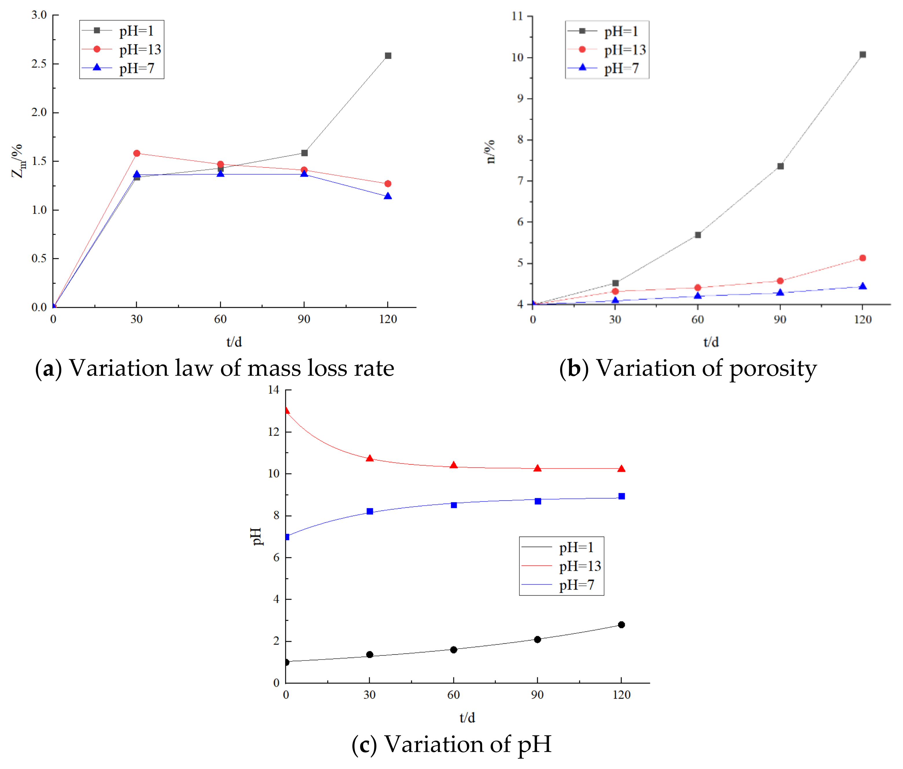
During the indoor long term accelerated corrosion test, a particular corrosion area was formed on the surface of the binary specimen. The generated material first filled the capillary pores of concrete and rock. When the filling amount reached the maximum value, the expansion stress continued to squeeze the capillary pore wall, further expanding the corrosion area. These cracks also lead to the gradual deepening of the seepage path. This phenomenon is particularly prominent at the rock–shotcrete interface, which is enough to cause the bonding performance at the interface to decrease significantly. In addition, in this process, the substances in the product that are slightly soluble in water were precipitated, resulting in significant changes in the mass of the binary specimen. The substances soluble in water also began to fluctuate in the pH value of the original solution. Figure 3 records the variations in physical and chemical properties in each corrosion cycle.
The mass loss rate, porosity, and pH value of the rock–shotcrete binary changed regularly under corrosive water. With the extension of corrosion time, the mass loss rate, after corrosion of acidic solution with pH = 1, increased. The mass loss rate of the alkaline solution and distilled water corrosion specimens decreased throughout the range of 30–120 d (Figure 3a). This is because the corrosion effect of binary specimens in alkaline and neutral environments is weak, and the chemical reaction between the specimen and the solution weakens in the middle and late stages of corrosion. The precipitation of the products from the pores becomes slow. The changing trend of the porosity of the binary specimen after corrosion in three different pH solutions is the same throughout the whole corrosion cycle (Figure 3b). Furthermore, the porosity of the specimen after corrosion in an acidic solution is more significant than that of the other two solutions. Significantly, the porosity of the corroded specimen in the acidic solution is more significant than the 96.36% and 127.03% of the corroded specimens in the alkaline solution and distilled water, respectively, at 120 d. The pH values of the three corrosive aqueous solutions changed rapidly at the initial stage of corrosion, and the pH change rates of alkaline and neutral solutions gradually stabilized at the later stage (Figure 3c). In contrast, the pH change rate of the solution began to accelerate in the acidic environment. Due to the strong corrosion effect of the acid solution on the binary specimens, microcracks and pores accumulated in the concrete and rock in the early stage of corrosion and, later, in turn, assisted the diffusion of corrosive ions. In addition, the corrosion solutions with pH = 1 and pH = 13 changed from solid acid to medium strong acid, and the strong base changed to a solid medium base after the corrosion stage. After the corrosion stage, the distilled water with pH = 7 showed as weak alkaline.
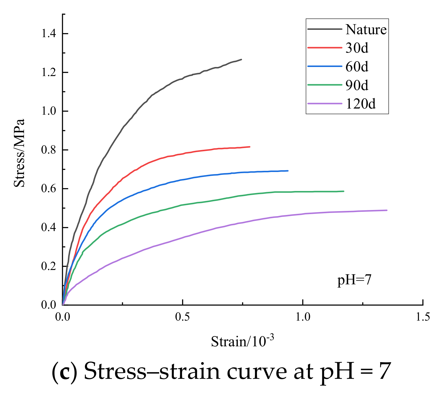
The stress–strain curves of the splitting tensile strength of the concrete–rock binary specimens under corrosive water were obtained in this experiment (Figure 4). The splitting failure process of concrete rock can be divided into the elastic, plastic, and failure stages. The growth trend of the splitting tensile stress–strain curves of the concrete rock binary interface under different pH values shows an upward convex state. At the beginning of loading, the stress growth rate increased rapidly, while the strain value increased slowly, and the stress–strain curve showed a linear change. With increasing days of corrosion, the elastic stage of the specimen decreased continuously, showing that the corrosion softening effect of the rock–shotcrete binary specimen under the action of corrosive water was increasing. After the elastic stage, the stress–strain curve gradually changes from linear to nonlinear. The stress growth rate slows down, and the strain changes abruptly under minimal stress. Since the magnitude of the strain peak point can reflect the deformation of the binary specimen in the splitting process, the larger the peak point, the greater the degree of softening. During the corrosion cycle, the peak values of the rock–shotcrete binary volumetric strain under different pH values continue to delay with time, showing the characteristics of flexible materials. When the specimen is subjected to tensile failure, due to the obvious brittle effect of the splitting tensile strength of the binary specimen, the failure is usually accompanied by a clear, brittle fracture sound. After failure, the stress drops rapidly, and the strain gauge is directly fractured, so that the strain value presents the limit value of the strain gauge. Therefore, the figure has no postfailure decline stage. The stress peak values of solutions with different pH values were also different. For example, the stress peak values of solutions with pH = 1 were 15.32%, 13.60%, 8.84% and 9.70% lower than those of solutions with pH = 13 and pH = 7 at 30–120 d, respectively. It can be seen that a solution with pH = 1 has the strongest effect on the interface erosion of the rock–shotcrete binary.

3.2. Analysis of Splitting Damage Evolution Based on Acoustic Emission Characteristic Parameters

3.2.1. Variation Characteristics of the Ringing Count of Acoustic Emission

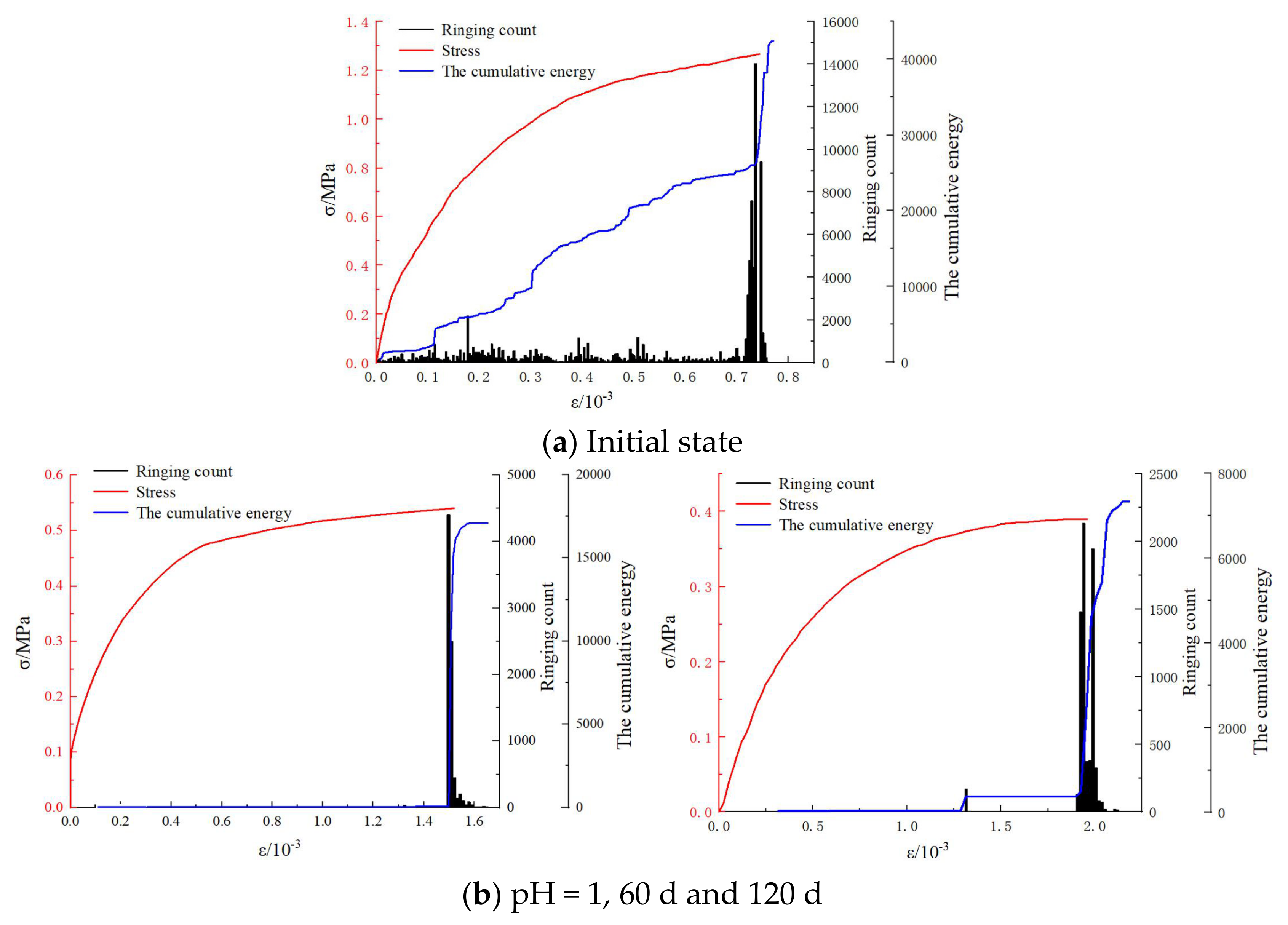
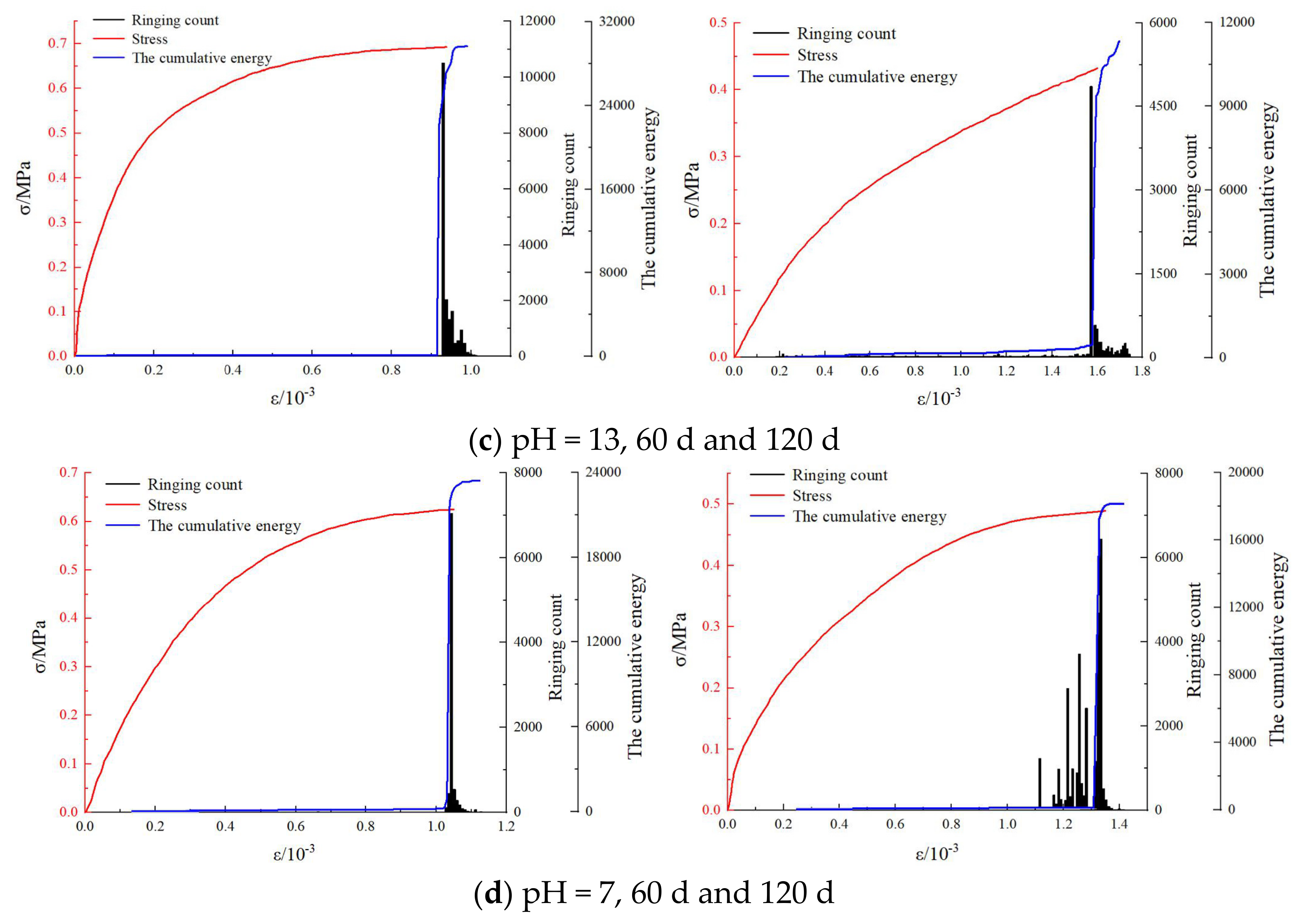
The acoustic emission ringing count refers to the number of times a rectangular pulse generated in a unit time exceeds the set threshold value, which is sensitive to the damage and deformation of geotechnical materials and is often used to evaluate acoustic emission activity [19]. The change rule of the ringing count of rock–shotcrete materials during the splitting tensile test is obvious, and the internal damage evolution law can be deduced. Figure 5 shows the relationship between ringing count, cumulative energy, and the stress–strain of binary specimens immersed in different pH values during the splitting test. Due to limitations of space, the acoustic emission parameters of the material were roughly the same as the immersion time extended. Therefore, only 60 d and 120 d data were selected for detailed analysis.
The change rule of the ringing count of the binary specimens immersed in different pH solutions can be divided into four stages: stable, development, mutation, and decline (Figure 5).
(1).
Stationary period. The number of ringing counts is small during this period, and acoustic emission events are also rare. Even the ringing counts of specimens corroded by corrosive aqueous solutions are negligible. In the early elastic stage of the specimen being under load conditions, the energy accumulated by the external load is not enough to destroy the cohesive force between the interface and produce new microcracks. With the application of the load, energy continues to accumulate, the microcracks caused by the primary hole begin to form, and the cohesive interface force begins to resist the transverse stress. The elastic stress wave released by the mechanical occlusion is captured, and the ringing count begins to respond. From the later elastic stage to the early plastic stage, the acoustic emission events enter a relatively stable period, primarily limited to about 1000 occurrences. Compared with the initial state, due to the erosion of the corrosive solution, the initial damage inside the specimen becomes extensive. Although the cracks are interconnected, most of them are filled with the generated material. The specimen become ‘soft’. The generated stress waves are mainly concentrated below the threshold value and are not captured.
(2).
Development period. In the late stage of the binary specimen entering the plastic zone, with the continuous increase of stress, the primary microcracks between concrete and rock continue to expand, and secondary microcracks are constantly generated. Therefore, a significant degree of fusion and penetration is formed on the bond surface, and the damage at the interface is more and more serious. The acoustic emission signal begins to be active, and a large oscillation wave is received. The ringing count enters the development period.
(3).
Mutation period. When the bonding force at the interface of the rock–shotcrete binary body reaches its limit, internal cracks gather rapidly, the first debonding occurs at the edge of the interface, the acoustic emission events increase rapidly, and the ringing count continuously exceeds the previous peak. The main crack at the interface breaks through the last obstacle by increasing the load. Furthermore, the ringing count reaches its maximum value almost at the moment before the failure of the specimen. The interface loses resistance to the ‘slamming’ sound and is destroyed. Due to the small interfacial bonding force and the short time required for the formation of a failure, the occurrence time of the peak value of the ringing count is often slightly ahead of the occurrence time of the peak stress point. Moreover, this phenomenon will become more evident with the erosion of corrosive water. Therefore, the precursor information of the interfacial splitting failure of a rock–shotcrete binary body under the action of corrosive water in the time domain should be the start time of the sudden change. The ringing count begins to increase significantly by several orders of magnitude.
(4).
Decrease period. After the mutation period, the interface is damaged but not fully debonded. At this time, emission events are still rare. The mechanical occlusion of the interface gradually fails with the expansion of the crack. The ringing count entered the decline period until zero.
The energy accumulated in the loading process is released in advance due to the loss of connection between the crystal particles on both sides of the interface following corrosion in different pH solutions. As the corrosion time increases, the peak value of the ringing count also decreases steadily. The size relationship can characterize the degree of corrosion damage when the interface is damaged by a splitting tensile. The more significant the peak value of the ringing count, the more minor the internal damage caused by corrosive water erosion. The ringing count peak value of the specimens soaked in an acid solution of pH = 1 is significantly lower than that of specimens soaked in an alkaline solution of pH = 13 and distilled water of pH = 7. The damage caused by the acid solution on the interface bonding force of binary is more significant than that of the other corrosive liquids, which is consistent with previous analysis.

3.2.2. Accumulated Energy Variation Characteristics of Acoustic Emission

Cumulative energy is the quantification of the accumulation of energy when damage occurs at the interface of binary specimens. It is a crucial parameter index of internal microstructure damage to materials. Studying the conversion of internal energy is helpful for us to understand the essential characteristics of splitting tensile failures of the rock–shotcrete binary interface [20]. The commonly used formula for acoustic emission energy is:
E = 1 R t 2 t 1 V ( t ) dt
where E is acoustic emission energy; R is the resistance value of the test line; and V(t) is the voltage function from t1 to t2.
It was found that the cumulative energy curve in the initial state is quite different from that in different periods of corrosion by solutions with different pH values, which can be roughly divided into the slow increase stage and steep increase stage (Figure 5). A slow growth period is apparent in the initial state, a ladder like climb. The internal damage of the binary specimen begins to expand under the load, and the energy continues to accumulate. The pores and cracks gather and penetrate, but the interface bonding force is still within the bearing scope. With the continuous application of the load, the energy reaches the limit, the main crack at the interface is broken, and the energy is released in large quantities. The cumulative energy curve is mutated and has an effect synchronous with the ringing count. However, the first stage of the binary specimen being corroded by corrosive water is not apparent, and even a sudden change occurs directly, indicating that the solution corrosion effect is noticeable. The initial damage inside the rock–shotcrete binary is severe, the upper limit of the energy-saving value is reduced, and the energy before the limitation is exhausted. Only a large amount of energy is released when the damage occurs, and the peak energy decreases with the corrosion strength and number of corrosion days of corrosive water.

3.2.3. Variation Characteristics of Acoustic Emission b Value

Due to its unique physical significance, the b value plays a vital role in earthquake early warnings. Subsequently, the concept of the b value was also introduced in acoustic emission [21]. Strain energy release caused by acoustic emission events in the tensile splitting process of the rock–shotcrete binary specimen can be regarded as a kind of micro-seismic activity. By comparing the size relationship of the acoustic emission b value, the size of the crack propagation scale at the interface of binary specimen in different corrosion cycles can be analyzed. The more significant the b value, the larger the ratio of small events to significant events.
Based on the Gutenberg–Richter relation and acoustic emission raw data, the acoustic emission b value can be calculated. The calculation formula is as follows:
lg N = a b M
M = A a B / 20
where M is the earthquake’s magnitude; N is the number of earthquakes in the range of M + ΔM; a and b are constants; and AaB is acoustic emission amplitude. In seismology, acoustic emission amplitude is usually divided by 20 to replace the seismic magnitude.
The acoustic emission amplitude data are counted with Δ A d B = 0.2 dB, and the formula for calculating the acoustic emission b value is:
b = i = 1 m M i i = 1 m lg N i m i = 1 m lg N i m i = 1 m M i 2 i = 1 m M i 2
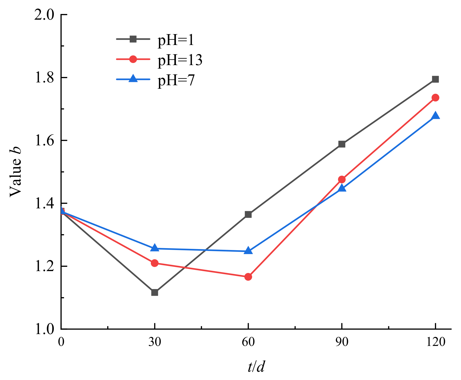
The acoustic emission b values of solutions with different pH values in different corrosion cycles are calculated by Formula (3) and plotted in Figure 6. The variation of the acoustic emission b value shows a trend of first decreasing and then increasing. This further indicates that the cracks at the rock–shotcrete interface are mainly damaged at a large scale in the early stage of the action of corrosive water, due to the intense chemical reaction. The damage, at this stage, is a stage of substantial expansion. As the corrosion time goes on, the b value of the binary specimen increases and the prominent internal cracks are caused by the expansion and penetration of small scale cracks. The concrete part of the specimen becomes weak, and its C-S-H group’s “root stump” effect becomes weaker and cannot stick to the rock. Under the action of a low stress level, microcracks were generated, which led to the splitting failure of the specimen. Under the act of reducing stress levels, microcracks are produced, resulting in the splitting failure of the specimen. It is worth noting that the b value of the binary specimens immersed in an acid solution of pH = 1 began to increase after 30 days, while the b value of the acoustic emission of the binary specimens immersed in an acid solution of pH = 13 and 7 started to increase after 60 days. This is due to the more intense reaction of the rock–shotcrete binary specimens in acid solution, the more significant damage in the early stage, and the higher number of larger scale cracks in the specimen. The relationship of the b value between alkaline and neutral environments in different corrosion cycles can also be explained.

3.3. Analysis of the Deterioration Mechanism of the Rock–Shotcrete Interface Bonding Performance in Corrosive Water

Under the influence of macroscopic mechanics, the damage state of the internal unit is defined as the damage variable, which is an irreversible quantitative representation of the structural unit. It is usually not directly measured, and it needs to be indirectly obtained by intermediate variables. Kachanov et al. [22] defined it as:
D = A i A
where Ai is the pore area of the material failure surface; and A is the initial area of the cross-section of the material.
Furthermore, based on the research of Liu et al. [23]. The AE characteristic parameters that can replace the damage value, such as cumulative ringing count, are selected to describe the damage variable:
D f = C i C 0
where Df is the loaded damage factor; Ci is the cumulative ringing count when the interfacial damaged area of the binary specimen reaches Ai; and C0 is the cumulative ringing count of interface area A when wholly destroyed.
Based on the strain equivalence principle, the damaging strain under the act of little stress σ is equal to the nondestructive strain under the action of equivalent stress. The constitutive relationship of geotechnical materials can be defined as:
σ = E ( 1 D ) ε
The damage at the interface of the rock–shotcrete binary specimen is not simply a single point of damage but the accumulation of the corrosion damage under the action of corrosive water and the load damage caused by corrosion, as shown in Equation (8).
D c = D t + D f D t D f
where Dc is the total damage of the binary specimen under interface corrosion and load; Dt is the corrosion damage factor; and Df is a coupling term.
Through Equations (7) and (8), the constitutive relationship of the rock–shotcrete binary specimen interface after corrosion loading can be obtained as follows:
σ = E 0 ( 1 D c ) ε
where E0 is the elastic modulus of the binary specimen in its initial state.
With the progression of corrosion, the interfacial bonding performance of the binary specimens gradually decreased. To characterize the internal damage deterioration degree, the elastic modulus measured at each corrosion stage is selected as the damage variable of the corrosion damage factor:
D t = 1 E t E 0
where Et is the elastic modulus at time t.
Uniting (6), (9) and (10), the total damage evolution equation of rock–shotcrete interface corrosion under load can be obtained:
D c = 1 E t E 0 C 0 C d C 0
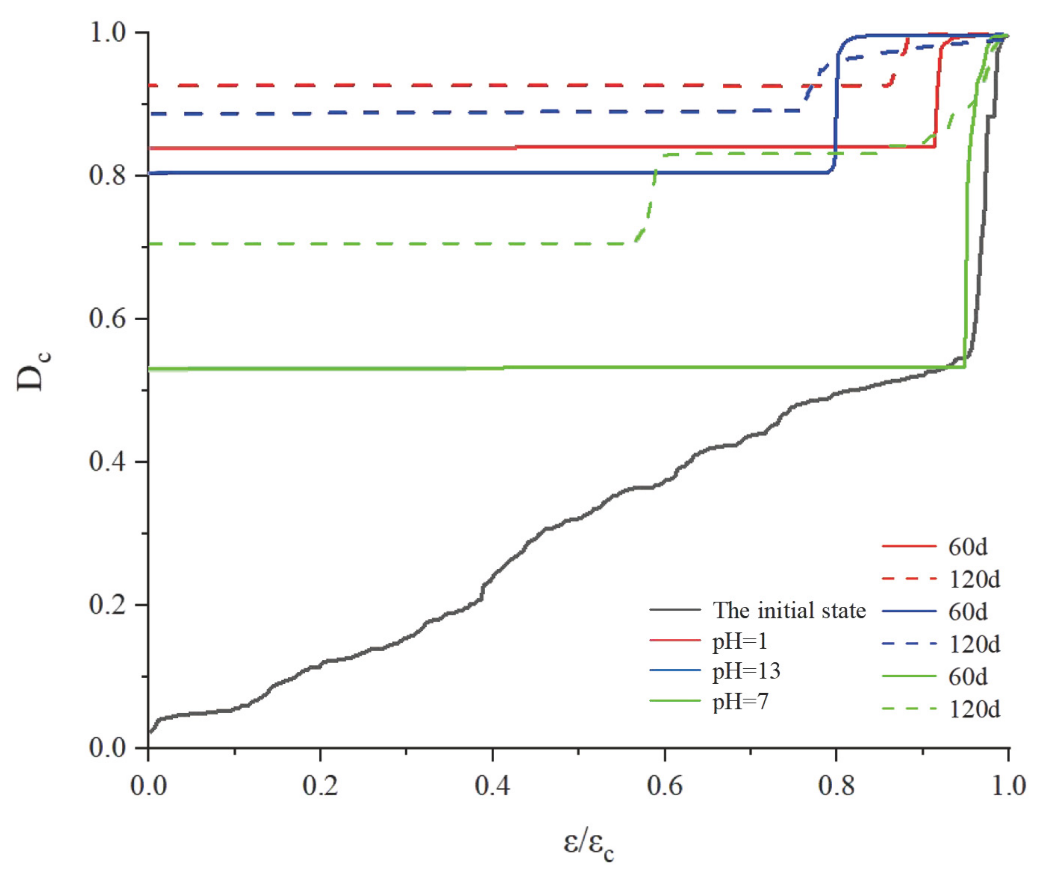
According to Formula (11), the damage evolution process of the rock–shotcrete binary interface bonding performance is quantitatively analyzed. The corresponding relationship between the damage variable and the relative strain is shown in Figure 7.
For the binary specimen subjected to corrosive water, with the decrease of pH value and the increase of corrosion time, the initial internal damage caused by corrosion increases. The initial damage value of the specimen corroded by the acid solution is significantly greater than that of the specimen corroded by alkaline and distilled water. Due to the continuous increase of microdefects in the binary interface caused by corrosion, local damage occurs at the interface under minor stress. Therefore, with the increase of corrosion days, the inflection point of the sudden damage degree also arrives earlier.

4. Conclusions

(1).
The physical and chemical properties of rock–shotcrete binary specimens subjected to different corrosive water erosion have changed dramatically in the time domain, and the interface bonding performance decreases continuously. The H2SO4 solution with pH = 1 has a relatively significant corrosion effect.
(2).
The variation of the ringing count, cumulative energy, and acoustic emission b value can better characterize the quantity of rock–shotcrete interface corrosion damage and the dynamic evolution process. With the increase of corrosion, the peak point of the acoustic emission characteristic parameters of the binary specimen decreases gradually during the splitting process. Its transition time in numerical values can be used as precursor information for splitting failure. The specimen’s expansion scale of damage cracks is first large and then reduced.
(3).
The total evolution equation of the rock–shotcrete interface damage variable based on the acoustic emission cumulative ringing count can better reflect the coupling relationship between corrosion environment, load, and damage. Compared with the initial state specimens, the initial damage of the corroded binary specimens is more extensive, and the damage degree develops rapidly during loading.

Author Contributions

Conceptualization, S.T., Y.S. and S.L.; funding acquisition, S.L.; investigation, S.T., W.M., Y.L. and X.L.; methodology, S.T. and Y.S.; visualization, Y.S.; writing—original draft, S.T.; writing—review and editing, S.L. All authors have read and agreed to the published version of the manuscript.

Funding

This research was funded by Shaanxi Province Natural Science Basic Research Program, grant number 2022JQ-563; China Post-Doctoral Science Foundation, grant number 2020M673525; Chine Railway 20th Bureau Group Co. Ltd. (Xi’an, China), grant number YF2000SD01A; and National Natural Science Foundation of China, grant number 42077274 and 41172237.

Institutional Review Board Statement

Not applicable.

Informed Consent Statement

Not applicable.

Data Availability Statement

The data included in this study are available from the corresponding author upon request.

Conflicts of Interest

The authors declare no conflict of interest.

References

  1. Wang, L.; Li, J.; Zhao, N.; Ren, X. Weak field control of rock engineering system failure. J. Liaoning Univ. Technol. (Nat. Sci. Ed.) 2005, 24, 671–673. (In Chinese) [Google Scholar]
  2. Shen, Y.; Wei, X.; Yang, G.; Wang, Y.; Jia, H.; Zhang, H.; Zhang, H. Rock-concrete interface bond strength freeze-thaw degradation model and experimental analysis. Rock Mech. Eng. 2020, 39, 480–490. [Google Scholar]
  3. Chen, Y. Application of acoustic emission technology in rock mechanics research. J. Geophys. 1977, 20, 312–322. [Google Scholar]
  4. Li, X.; Wu, X.; Gao, S.; Zhu, B. Experimental study on uniaxial compression and acoustic emission characteristics of red-bed soft rock under chemical corrosion. Railw. Sci. Eng. J. 2015, 69, 80–84. (In Chinese) [Google Scholar]
  5. Liu, Y.; Wang, C.; Li, X. Coupling study of acoustic emission and infrared radiation of sandstone under water-rock interaction. J. Yangtze Acad. Sci. 2022, 39, 127–133. (In Chinese) [Google Scholar]
  6. Zhang, G.; Li, H.; Wang, M.; Li, J.; Deng, S. Comparative study on damage characterization and evolution law of rock under uniaxial compression. Geotech. Eng. J. 2019, 41, 1074–1082. (In Chinese) [Google Scholar]
  7. Zhang, L.; Zhao, Y.; Jiang, A.; Ni, Q. Study on shear properties and acoustic emission characteristics of acid corroded concrete. J. Build. Mater. 2011, 14, 385–388. (In Chinese) [Google Scholar] [CrossRef]
  8. Sun, B.; Liu, H.; Yuan, D.; Wang, F.; Zeng, S. Research on damage characteristics of rock-concrete in two media under dry and saturated conditions. Silic. Bull. 2019, 269, 177–182. (In Chinese) [Google Scholar]
  9. Su, H.; Zhang, Y.; Li, Q.; Yuan, Z.; Gao, X. Acoustic emission test of the rock-concrete integrated two-medium body combined with discrete element method. Sci. Technol. Eng. 2019, 19, 206–210. (In Chinese) [Google Scholar]
  10. Liu, H.; Lin, J.; Yang, G.; Yun, Y.; Zhang, H.; Liang, B.; Zhang, Y. Acoustic emission test of tensile damage characteristics of sandstone under freeze-thaw cycles. J. Min. Saf. Eng. 2021, 38, 830–839. (In Chinese) [Google Scholar]
  11. Li, H.; Yang, C.; Liu, Y. Experimental study on acoustic and acoustic emission characteristics of salt rock under uniaxial loading. Rock Mech. Eng. 2014, 33, 2107–2116. [Google Scholar]
  12. Li, S.; Yin, X.; Wang, Y.; Tang, H. Research on acoustic emission characteristics of rock failure process under uniaxial compression. Rock Mech. Eng. 2004, 15, 2499–2503. (In Chinese) [Google Scholar]
  13. Yao, Q.; Li, X.; He, L.; Zhou, J. The strength damage and acoustic emission characteristics of water-bearing sandstone under uniaxial compression. J. Min. Saf. Eng. 2013, 30, 717–722. (In Chinese) [Google Scholar]
  14. Su, C.; Zhai, X.; Li, B.; Li, H.Q. Experimental study on acoustic emission characteristics of sandstone during uniaxial and triaxial compression. J. Min. Saf. Eng. 2011, 28, 225–230. [Google Scholar]
  15. Ji, H.; Lu, X. Acoustic emission characteristics of granite and its main fracture precursor information under conventional triaxial compression. J. Rock Mech. Eng. 2015, 34, 694–702. [Google Scholar]
  16. Wu, K.; Shao, Z.; Qin, S.; Zhao, N.; Chu, Z. An improved non-linear creep model for rock applied to tunnel displacement prediction. Int. J. Appl. Mech. 2021, 13, 2150094. [Google Scholar] [CrossRef]
  17. Wu, K.; Shao, Z.; Sharifzadeh, M.; Chu, Z.; Qin, S. Analytical approach to estimating the influence of shotcrete hardening property on tunnel response. J. Eng. Mech. 2022, 148, 04021127. [Google Scholar] [CrossRef]
  18. Wu, K.; Shao, Z.; Sharifzadeh, M.; Hong, S.; Qin, S. Analytical computation of support characteristic curve for circumferential yielding lining in tunnel design. J. Rock Mech. Geotech. Eng. 2022, 14, 144–152. [Google Scholar] [CrossRef]
  19. Wu, X.; Liu, J.; Liu, X.; Zhao, K.; Zhang, Y. Exploring the coupling relationship between cumulative counts of rock acoustic emission ringing and damage constitutive model. J. Min. Saf. Eng. 2015, 32, 28–34. (In Chinese) [Google Scholar] [CrossRef]
  20. Qin, S.; Li, Z. Fractal distribution of rock acoustic emission events in space. Appl. Acoust. 1992, 11, 19–21. [Google Scholar]
  21. Han, J.; Yao, L. Crustal stress evaluation method based on seismic activity parameter b-value. Rly. Std. Desg. 2015, 59, 36–39+127. (In Chinese) [Google Scholar] [CrossRef]
  22. Kachanov, M. On the time to failure under creep conditions. Izv. Akad. Nauk. USSR Otd. Tekhn. Nauk. 1958, 8, 26–31. [Google Scholar]
  23. Liu, J.; Zhao, L.; Song, S.; Ji, H. Acoustic and acoustic emission characteristics and mechanism of concrete sulfate corrosion damage. J. Eng. Sci. 2016, 38, 1075–1081. (In Chinese) [Google Scholar] [CrossRef]
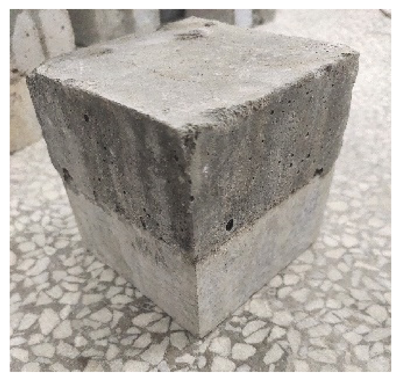
Figure 1. Rock–shotcrete binary specimen.
Sustainability 14 04987 g001
Figure 2. Test device diagram.
Sustainability 14 04987 g002
Figure 3. Changes of physical and chemical properties in different corrosion cycles.
Sustainability 14 04987 g003
Figure 4. Stress–strain curve of rock–shotcrete splitting under corrosive water.
Sustainability 14 04987 g004aSustainability 14 04987 g004b
Figure 5. Variation of acoustic emission parameters.
Sustainability 14 04987 g005aSustainability 14 04987 g005b
Figure 6. A figure of b-value variation of acoustic emission.
Sustainability 14 04987 g006
Figure 7. Corrosion damage evolution curve of the rock–shotcrete interface under load.
Sustainability 14 04987 g007
Table 1. Composition and mass fraction of rocks.
Petrographic CompositionSiO2Al2O3CaOK2ONa2OFe2O3
mass fraction
%
70150.91.10.30.4
Table 2. A mix ratio of shotcrete (kg/m3).
NameTaking ValuesNameTaking Values
cement398water-cement ratio0.44
water175percentage of sand31%
river sand566rapid setting admixture23.88
crushed stone1261Water reducing admixture3.98
Table 3. Mechanical properties of materials.
MaterialDensity
(kg/m3)
Poisson RatioElastic Modulus(GPa)Compressive Strength (MPa)
concrete24000.2030.2738.13
rock25900.2450.3485.36
Publisher’s Note: MDPI stays neutral with regard to jurisdictional claims in published maps and institutional affiliations.