Abstract
China’s energy structure mainly depends on coal resources, which will still play the dominant role in economic development in the future. With the mining depth increasing, the deep roadway construction will be exposed to a complex stress environment, increasing the difficulty of roof control and further hindering the mining activities. The problem of deep roadway excavation causing significant fracture scope of surrounding rock in and outside the anchorage zone has attracted much attention. For the large crack scope existing in the roadway roof of deep underground openings, this paper focuses on the exploration of upgrading the support system. In order to solve this problem, we investigated the zone damage of the roadway roof with the discrete element model using the UDEC trigon method and damage quantified evaluation with data analysis. The long anchorage and zone linkage support technology was proposed based on the damage control effect of varying lengths of supporting bolts. The purpose of extending the length of bolts is to link the more severely damaged rock mass in the shallow part to the minimum damaged part in the deep place, aiming to form the thick anchor zone to mobilize the rock mass in each zone to participate and bear the load together. Furthermore, the onsite application of long anchorage and zone linkage technology gained good control effects in the selected typical roadway with different geological conditions. The results show obvious resistance in cross-section shrinkage, integrity maintenance, and minimization of crack scope in the roadway roof. The promotion of long anchorage zone linkage technology can help the mine with similar situations uplift the efficiency of working and guarantee the safety of miners during mine service life in the deep coal roadway.
1. Introduction
China’s energy structure is “rich coal, poor oil, less gas,” which determines that China’s energy consumption will continue to place coal consumption at the top of the list of energy plans [1].
Technology renovation and exploration in the coal mine are still needed. With the depletion of coal resources at shallow depth, China’s coal development is rapidly progressing deeper at the rate of 10 to 25 m per year [2].
As the mining depth increases, the stress state of the mining environment becomes complex, in which the rock mass suffers high stress from both the rock measures above and the construction stress [3,4]. As a common phenomenon, after excavating deep underground openings, the equilibrium state of the original rock mass is broken. With the redistribution of high ground stress, cracks evolution will occur in and outside the short bolts anchorage zone and will tend to develop in a large scope [5], which increases the difficulty of roof control in the deep roadway [6]. During roadway driving in deep coal measures, micro damage and irreversible plastic zones occur [7], and roof fall will happen progressively, which stops the operation of mining machines and poses a big threat to human security. In order to guarantee the safety and efficiency of mining activities in the deep roadway, maintaining the roof stability of the deep underground roadway should be given top priority.
Efforts are underway to explore applicable technology for roof control in deep underground openings. Many researchers have undertaken much work to analyze the failure mechanism of the deep roadway and have provided a series of measures to cope with the roadway stability problems.
Kang [8] took the deep high-ground stress roadway as the research background, analyzed the deformation and failure mechanism of the surrounding rock, and proposed the high pre-stress and strong bolt system. Furthermore, the support system was applied successfully in engineering practice. Zuo [9] studied the surrounding rock’s stress characteristics and distribution law and proposed a theoretical support model considering failure gradient. Moreover, under the guidance of the equal-strength support model, the comprehensive support system successfully gained a good control effect on the roadway stability maintenance by adjusting the stress state of the surrounding rock. Jing [10] explained that the support object is the deformation pressure determined by the rock failure expansion based on the loose zone support theory. Additionally, forming a stable support-surrounding rock structure is critical to achieving a safe state of surrounding rock in deep mines. Given the deep roadway surrounding rock strength reduction, stress environment deterioration, surrounding rock structural instability, large deformation, and other problems, Hou [11] used methods including theoretical analysis, numerical simulation, and field test to quantify the interval of macroscopic damage, proposed the grouting technology of shallow hole sealing and grouting and deep hole reduction and reinforcement, and successfully improved the integrity and stability of the surrounding rock. Additionally, Hou [12] emphasized that high pre-stress and strength of the supporting system are the key factors to maintaining support structure. Zhang [13] sorted the surrounding rock into different control levels. For each level, the “high strength, high pretension, and high rigidity” bolt was proposed and achieved good control effects with field testing. For the deformation control of deep coal roadway under high stress and mining pressure, Wang [14] devised a support technology with bolt-mesh belts to deal with the deformation in targeting coal seam roadway. Considering the difficulty of controlling surrounding rock in the deep roadway with the large section and thick top coal, Xiao [15] analyzed the shear failure mechanism in the bedding surface between top coal and the immediate roof and proposed a support system including the high pre-stress bolt and diagonal cable. The support system has a good control effect on shrinking the scope of the plastic zone and constraining the development of shear deformation. To construct the classification system of surrounding rock in deep mines, Yuan [16] used a series of methods to analyze the roadway deformation mechanism and instability evolution. With the classification system, technical measures were applied successfully in targeted deep mines, where the surrounding rock strength improved, peak stress transferred, and the bearing zone enlarged. Xiao [17] used numerical simulation to study the influence of shoulder bolt fixing angle on the roadway surrounding rock control and proposed a control technique for shoulder area safety. In order to control the large deformation of surrounding rock, Xie [18] analyzed the deformation characteristics, stress distribution, and failure zone developing laws of surrounding rock in deep coal mines, revealing the space- and time-evolving instability mechanism by which the support design, with different supporting strength measures, achieved a good control effect. For roadways with large deep mining depth, Xie [19] proposed a “truss anchor supporting roof beams” model and used the mechanical model to guide the design and support practice, which played a role in surrounding rock deformation control. Based on onsite observation, Wang [20] found that the anchor bolt could not exert anchor force within the damaged anchor foundation and the U-shaped steel arch failed to shoulder the bearing capacity. Thus, a support system with square steel confined concrete was proposed and verified by the monitoring results. For deep coal roadways via onsite research, Xie [21] extended the length of supporting bolts to enlarge the thickness of the anchor structure and combined the mine bolter to construct a rapid excavation supporting system. The system played an important role in prohibiting fracture evolution, which was verified by the borehole images from engineering practice. Wang [22] set up a theoretical analysis and a series of experiments concerning the large nonlinear deformation in the deep coal mine and designed the coupling support techniques with CRLD. Yang [23] selected a deep coal roadway as the research ground, applied the long high-performance bolt to construct a large thickness bearing zone in the roadway roof, and analyzed the relationship of bolt resistance interacting with the surrounding rock. Zhao [24] proposed and applied the double-layer arch collaborative reinforcement technology in engineering practice, using the combination of shotcrete and anchor bolt with grout. For large-section chambers in deep mines, Zhu [25] proposed the “three shells” collaborative support technology to reduce the surrounding rock’s plastic zone and achieve an ideal stability control effect. For deep coal roadway with rheological behavior, Sun [26] constructed a time-dependent 3D numerical model with FLAC3D simulation software to analyze the instability mechanism of deep mines and provided applicable measures to maintain the roadway stability. Wu [27] conducted numerical research on the coal pillar damage analysis and proposed the applicable coal pillar width and support technology to maintain the roadway stability. Yang [28] studied the failure mechanism of large deformation in deep soft rock roadway and proposed the combined support technology.
The research methods of roof control in deep roadways in the aforementioned studies are various, including theoretical analysis, onsite experiments, and numerical simulation, which enable researchers to understand better the failure mechanism of surrounding rock by data acquisition of deformation variation, stress distribution, and fracture evolution. Based on this, control measures, such as support density improving, preload enhancing, and surrounding rock sealing, are proposed and obtain good control effects on roadway stability maintenance. However, constructing a thick bearing zone by long bolt installation and a deeper understanding of the impacting mechanism in terms of quantified rock mass damage in the roof remains to be researched. Therefore, to enrich the supporting field and upgrade roadway roof control technology, we explore the forming mechanism of the thick bearing structure by building the discrete element model with the Universal Discrete Element Code (UDEC) software trigon method and fish function to realize roof damage quantification and damage data analysis. Furthermore, the long anchorage and zone linkage support technology was proposed and testified in the typical roadway roof with different geological conditions. The controlling experience can be applied to other roadway roof stability maintenance involving similar excavation situations.
2. Geological Conditions
We selected the soft rock layer of the roadway roof in Liuzhuang coal mine as the research target to study the characteristics of zonal damage and the mechanism of long anchorage zonal linkage technology. The stratigraphic column obtained from the 11-2 coal seam is shown in Figure 1, and the coal seam’s average buried depth and thickness are 615 m and 4.2 m, respectively. The lithology of the roadway roof from bottom to up is mainly mudstone and fine sandstone with the thickness of 4 m and 5.4 m, respectively. The roadway floor is composed of sandy mudstone (3.6 m) and fine sandstone (16.4 m). The dip of this coal seam is nearly flat, with a dip of 3°.
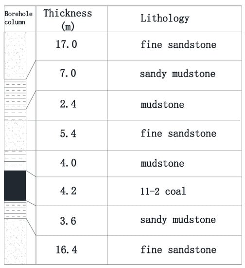
Figure 1.
Comprehensive geological bar chart.
3. Calibration of Microscopic Parameters of Rock Masses
As the mechanical parameters of the rock masses obtained in the laboratory usually have fewer joints and fractures, the resulting mechanical parameters cannot reflect the actual situation of the field conditions. Therefore, to better reflect the actual status of rock excavation in the field, the mechanical parameters of the rock masses obtained in the laboratory are transformed by empirical equations to obtain the relevant mechanical parameters close to the rock masses for numerical simulation analysis.
Zhang [29] developed a conversion between the modulus of rock mass and intact rock with the help of Equation (1) using the RQD values obtained from each lithology, where is the deformation modulus characterized by rock mass and is the deformation modulus of the intact rock.
The rock mass’s uniaxial compressive strength is computed using Equation (2), where σcm and are the uniaxial compressive strength of the rock mass and rock block, respectively [30]. The index n corresponds to several modes of rock masses in a more extensive range of slip, splitting, shear, and rotation. As the roadway excavation in the coal seam will induce different failure modes of surrounding rock, and based on the available literature, n = 0.63 is chosen here [27]. Table 1 contains the calibrated parameters.

Table 1.
Parameters’ transition between intact rock and rock mass.
The deformation modulus obtained above and the corresponding Poisson’s ratio μ of the rock block are brought into the following Equations (3) and (4), where K means bulk modulus and G means shear modulus.
The parameters on the contact surface are calculated through Equations (5) and (6), where is the normal stiffness of the contact surface and is the tangential stiffness of the contact surface. ∆Zmin is the edge length of the shortest side between the contacting blocks. Additionally, the microscopic mechanical parameters of different lithology should be calibrated in the area of interest. The selected uniaxial compression test model is consistent with the focus study area onsite in two aspects: the first is the selection of the block with the same triangular block. The second is a height diameter ratio of 1:2 based on the size of the roadway range, to maintain consistency and avoid the impact caused by the size effect.
The initial values of micro parameters such as friction angle, cohesion, and tensile strength of the joints are based on empirical values. Then the microscopic parameters on the contact surfaces are adjusted by continuous parameter optimization to obtain a consistent characterization with the rock samples’ macroscopic mechanical parameters: modulus of elasticity and compressive strength. The strata layer parameters above and below the main mining seam are calibrated. The calibration curves and fracture patterns of each lithology are shown in the following Figure 2. Finally, the microscopic parameters are listed in Table 2.

Figure 2.
Uniaxial compression and calibration of rock mass parameter.

Table 2.
Mechanical properties of rock and contact.
4. Model Building
A two-dimensional numerical simulation model was constructed with the calibrated parameters for simulating the roadway excavation and fracture evolution. The length of the model is 60 m in both the horizontal and vertical directions. The width and height of the roadway section are 5.4 m and 3.2 m, respectively, as is shown in Figure 3.
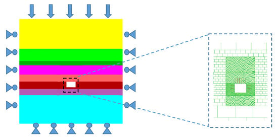
Figure 3.
Numerical simulation diagram.
As the roadway was at a deep depth, the influence of ground stress on working conditions cannot be neglected. Therefore, the vertical and horizontal ground stresses were applied to the model with a scale factor of 1.2. The horizontal stress was 18.5 MPa, and the vertical stress was 15.4 MPa. The constitutive model assigned to the blocks in this simulation was the elastic model, and the contact between the blocks followed the coulomb model strength criterion. The constructed model had properly meshed, and the stresses were applied to the model. Finally, the model was calculated to the initial equilibrium state. After that, the following steps, including excavation of the roadway, support, and data monitoring, were carried out. By enhancing the efficiency of running models, the grid size increased progressively from the place near the excavation area to that far away near the boundary side. Grids were selected in two forms: trigon and rectangular, in the area of interest, and the rest of the grids in the model, respectively.
5. Numerical Results
5.1. No Support with Different Thicknesses of the Soft Roof
Based on the existing support technology, this section selected the variation of the thickness of the soft layer within the range of 2 m to four times the length of conventional bolts to carry out the relevant research. The relationship between the thickness and fracture expansion of the soft layer and rock damage was investigated. Under the same calculation steps of model running with different thickness of soft layers, the simulated results can be compared and analyzed with thickness of soft layers varying. The calculation steps can be treated as the running time, and it will be recorded by the software automatically, during which the simulated model after the roadway excavation will present roof fall and deformation of the roadway cross section.
5.1.1. Crack Evolution Features
In different models, the thicknesses of soft layers in the roadway roof are set as 2 m, 4 m, 6 m, and 8 m, respectively. When the thickness of the soft layer is 2 m, the fissure expands along the roadway roof to a position around 2 m, almost occupying the whole range of the roadway roof. As the operation time progresses, the existing fissures penetrate through each other and progressively develop to the left and right sides of the roadway roof. When the thickness of the soft layer of the roadway roof increased to 4 m, the fissures also showed a trend of upward development. The fissures extended to 3 m in the roadway roof, and there was also the trend of fissure development expanding to both sides, but the performance was not as severe as that of the 2 m soft layer. When the thickness of the soft layer of the roadway roof increased to 6 m and 8 m, respectively, the height of the fissure extension of the roof area did not change significantly. The initiation, nucleation, and extension of fissures are mainly concentrated in the shallow range of 3 m of the roof strata, and the formed fissure also tended to extend to both sides.
The fracture extension of different soft layer thicknesses without support is shown in Figure 4.

Figure 4.
Crack distribution with different thicknesses of the soft layer.
5.1.2. Deformation Variation
As shown in Figure 5, monitoring points (al, bl, cl, and dl) were arranged at the center of two ribs, top and bottom of the roadway, to record the displacement changes on the surface of the surrounding rock after the roadway excavation.
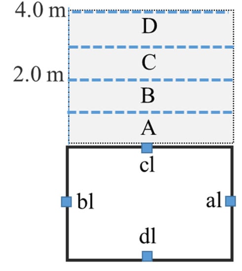
Figure 5.
Roof zonal division.
With the growth of the model’s time step, the displacement of the various parts of the roadway surface continued to grow. Thicknesses of 2 m, 4 m, 6 m, and 8 m of the soft layer of the roof displacement reached 631 mm, 1141 mm, 1339 mm, and 1331 mm after the roadway excavation, and the floor displacement was 697.3 mm, 743.9 mm, 775.8 mm, and 733.1 mm. With the increase of the thickness of the soft layer, the deformation of the roof also increases. The comparison graph of the displacement curve of different thicknesses of the soft layer is shown in Figure 6.
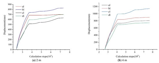
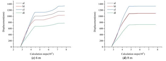
Figure 6.
Displacement of roadway surrounding rock with different thicknesses of the soft layer.
5.1.3. Damage Quantification
In Figure 5, we divided the soft layer in the roadway roof into several equal areas: A, B, C, D, etc. These were consistent with the width of the roadway and 1 m high, respectively. Considering the integrity of the soft rock in the roof is the key factor affecting the stability of surrounding rock, the damage monitored areas were set in the soft rock part of the roadway roof.
The fracture morphology and length of tensile and shear cracks after roadway excavation are recorded through UDEC’s customized Fish language. The parameter D means damage in surrounding rock; in particular, the contacts between different blocks failed under the action of shear or tensile stress in the monitored regions. The damage D was proposed by Gao [31]. The damage degree of the roof is explored through the proportional relationship of the fracture length below.
LC represents the total length of contact, and LS and LT mean the total shear length and total tensile length, respectively. Additionally, the shear damage and tensile damage can use the ratio relationship to represent the damage situation.
Figure 7 shows the fracture distribution of roadway surrounding rock, from which the red line identifies the shear fracture, and the green line identifies the tensile fracture. The shallow part of the roadway surrounding rock is dominated by tensile fissures that are mainly concentrated within 1 m of the roadway surrounding rock. Moreover, the roof in a deeper place has many shear fissures.

Figure 7.
Damage analysis of 2 m soft layer in the roof.
The damage ratio in both areas was counted respectively, where Aa and Ba represent the damage values in each area. After the roadway excavation, the roof damage was a continuous cumulative process, and the final damage amount in area A reached nearly 95%. With the time step running on, stress caused by the excavation of the roadway was transferred to the 1–2 m range of the roadway roof, area B, which caused the rock in this range to be loaded and form fissures. The rock formed a certain range of damage, and the final damage amount was 60%. Compared with zone A, the amount of damage in zone B was significantly reduced, indicating that the rock mass in the higher strata is more stable than that in the shallow place.
With the increasing thickness of soft layer, Figure 8 shows the distribution pattern of fractures in the roadway surrounding rock for a 4 m thickness of the soft layer at the top of the roadway. As with the 2 m thickness of the soft layer of roadway roof, tensile fractures exist in the shallow part of the roadway surrounding rock, and shear fractures occupy most of the surrounding rock. The 4 m soft rock layer above the roadway roof also has four separate areas of 1 m. After plotting damage variables of respective areas, we can see that the damage variation in the shallow range of 2 m in the roof has the same trend and values as the 2 m soft layer. As the time step proceeds, damage occurs in different layers in the roof, with damage statistics of 41% and 18% between 2–3 m and 3–4 m, gradually becoming smaller as the vertical distance from the roof surface of the roadway increases. The damage variation in the four areas showed the same gradual development trend in the initial roadway excavation stage.

Figure 8.
Roof partition and damage analysis of 4 m soft layer in the roof.
From Figure 9 the fracture extension exhibited by the 6 m-thick soft layer of the roadway roof did not change significantly compared with the damage pattern of the 4 m-thick soft layer of the roof. The blocks lose the relationship of mutual embedding and support, generating larger fissure space between blocks and blocks. The movement pattern of the block with the time step performance is rotation, slip, and dislodgement. The amount of damage in each region was counted, and the amount of damage in the first five regions was 95%, 72%, 55%, 35%, and 7%, respectively. The amount of damage in area 6 had minor changes. The crack development and damage change of 8 m thickness of the soft roof was similar to that of 6 m in each zone, and there was no greater change value, which will not be described here.
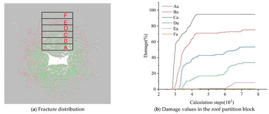
Figure 9.
Roof partition and damage analysis of 6 m soft layer in the roof.
5.2. Control of Roof Damage by Different Lengths of Cables
From the previous chapter, the fractures in the roof develop progressively, which has the main trend from the shallow part to the deeper place out of the short bolts anchorage range. In order to inhabit the damage within and outside of the short bolts anchorage scope, we investigate the control effect of long anchorage support by varying the length of bolts through UDEC software. To better understand the control law of the thick anchorage layer and zonal linkage action, a single variable was controlled by choosing 4 m thick soft roadway roof setting bolts with different lengths of 2 m, 3 m, 4 m, and 5 m in the roof. At the same time, other parameters in the model were kept consistent with the last section. The 4 m height soft layer roof was also divided into four zones, and the damage values were recorded timely. In this simulation, “Bolt unit” is the bolt element installed in the surrounding rock, which is defined as the cable element incorporated in the UDEC software. “Structural unit” is the surface protection component, which is the streel strap in the practice.
The basic parameters of the corresponding anchorage units used in the numerical model simulations are as follows in Table 3. The support element properties were proposed by Gao [32].

Table 3.
Bolt anchorage unit parameters.
5.2.1. Crack Evolution Features
With the variation in bolt length, the evolution of the fracture is displayed in Figure 10. In the simulation, after giving timely support to the roadway surrounding rock and applying different length bolts, it can be seen from Figure 10b that the bolts play a significant role in inhibiting the development and expansion of fractures in the roof. The voids between detached blocks decrease. Moreover, the fracture development boundary shrinks inward in the scope height and width. With the length of bolts increasing, the fracture development scope has a decreasing trend. The installation of 2 m bolts in the roof can prohibit the fracture evolution to an extent. However, the end of the short bolts cannot anchor in a stable and less fractured area, which will easily lose the anchorage fundament due to stress disturbance. Therefore, extending the anchorage length and creating a thick and stable anchorage zone is important to maintaining roof stability.
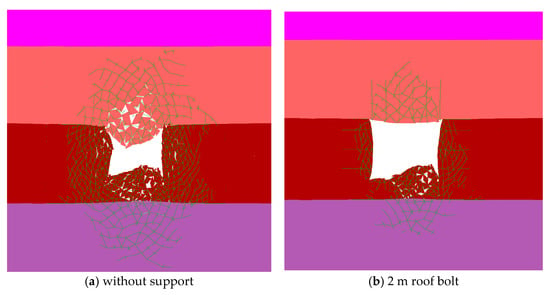
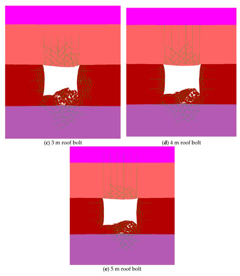
Figure 10.
Distribution of different support cracks in surrounding rock of roadway.
When the bolt length increases to 4 m and 5 m, the fracture scope shrinks, and the blocks in the anchorage range gain the feasibility to “reconnect” and support each other, eliminating the gaps and further realizing stress transferring effectively.
5.2.2. Roadway Roof Damage Control with Extending Length Bolts
Based on the above analysis of different bolt lengths on the control of roof fissures, the damage of each stratum was further quantified by comparing and analyzing the different bolt cable lengths without the support and with support in a pre-defined area.
From Figure 11, we can see that the main trend of damage variation in each zone decreases obviously with the increase in the bolt length.

Figure 11.
Statistics of damage amount in each zone of roadway roof under different support length.
In more detail, the comparative analysis of damage variation between roadway roofs without and with bolt support gives us an immediate impression of the damage control effect of bolt installation. Figure 11a shows the effect of controlling damage to the roof by applying 2 m bolts after excavating the roadway. The support of bolts and the supporting surface protection structures such as metal mesh and steel straps in the numerical simulation will be installed immediately after the roadway excavation. Compared with the statistical volume analysis without support, the acquired data on damage in each stratified area shows that the use of bolts greatly reduces the roof’s damage. The damage amount in the first area was reduced from 90% to 47%, and the shallow area was well controlled. Importantly, timely support after excavation is important for controlling the roof before the damage develops upward. Compared with the other three stratified areas, the damage was also controlled, and the damage value decreased to 22.5%, 2.5%, and 1%, respectively. Although the 2 m bolts can upgrade the roof’s stability overall, the limited anchorage range cannot inhibit the damage in the third zone. In contrast, the 3 m bolts installation can obtain better control on the third zone. Therefore, extending the length of bolts to penetrate the damaged area in shallow places is necessary to build a thicker bearing zone, which helps link the rock mass in the bolt anchorage range.
Compared with the roof damage of 2 m bolt length, the bolt with a 3 m or more length decreases the damage variation in the third zone and keeps the damage values small, shown in Figure 11b–d, whereas the damage variation in the fourth zone remains minor, indicating that this zone has not been seriously affected yet. Due to the installation of the long bolt, the thick bearing structure formed accordingly, which uplifted the overall integrity of the roadway surrounding rock. The rock block interacts with each other firmly within the bolt’s anchorage zone, and the rock mass in different height rock layers bear the stress together through the linkage of long bolts anchorage.
5.2.3. Roadway Surface Displacement
With the installation of bolts, the displacements of roadway surrounding rock were observed and plotted by changing the length of bolts. It can be seen from Figure 12 that the displacement of the roadway roof by changing the length of different bolts is 282.7 mm, 279.2 mm, 225.6 mm, and 196.8 mm, respectively. With the increase of the length of bolts, the deformation of the roof gradually decreases. The displacement of the roof gradually becomes smaller when the displacement of the roof increases from 2 m long bolts to 5 m. Furthermore, the roof integrity was better maintained as the length of bolts increased. Additionally, the displacement on both ribs and floor gained better control by installing long bolts. In practice, the length between 3 m and 5 m tends to use short cables to realize the roof support.

Figure 12.
Surrounding rock displacement of the roadway under different bolt lengths.
6. Engineering Practice
From the mechanism of long anchorage zone linkage via UDEC damage quantified analysis, the long bolt can form a thicker anchorage zone, in which the rock mass in each zone can bear stress together and prohibit the fracture evolution. Therefore, it is necessary to conduct engineering practice to verify the long anchorage zone linkage technology. Through onsite research, we selected typical roadways with different roof structures. Apart from extending the length of bolts to form a thicker anchorage zone, we also focused on surface protection of the roadway roof with high stiffness components.
The selected roadway is in the Hulusu mine. The coal seam depth at the working face is large, about 670 m; the coal seam thickness varies greatly, from 1.87 m to 3.55 m, with an average of 2.71 m. The lithology of the research site is shown in Figure 13. Under the original support plan, the fissures observed onsite reach outside the short bolts anchorage range, threatening roof stability. A revised support plan with 4m bolts length focusing on roof control was proposed and implemented in practice, taking into account the short bolts anchorage range and maximum crack development range. The cross-section of the targeted roadway is rectangular: 5.4 m in width and 3.2 m in height. The major support parameters are plotted in Figure 14.

Figure 13.
Comprehensive geological column of research site.
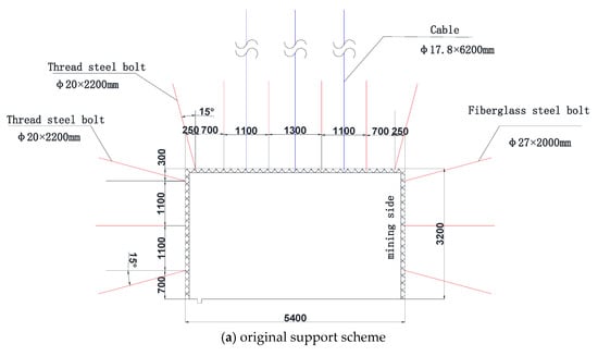
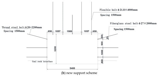
Figure 14.
Roadway support schemes.
Under the new support scheme, the fissures observed in the peeping hole decreased obviously. From Figure 15, the bedding separation and fragmentation were all concentrated within 1 m, restraining the fissures under the normal short bolts anchorage zone and providing remarkably improved roof control effects. The long anchorage control with long bolts in similar roof conditions was applied successfully [23].

Figure 15.
Peeping images of the borehole.
Furthermore, we chose another case to verify the long anchorage zonal technology with a combined soft and hard rock structure roof. The geological column of the research site is displayed in Figure 16. By comparing the deformation data acquired from the original section and new development support measures, the long anchorage zonal linkage can restrain the roof deformation to some certain extent.

Figure 16.
Comprehensive geological column of research site.
As shown in Figure 17, with the idea of linking rock mass in the different zonal divisions of the roadway roof, in this case, we extended the length of the bolt from 2500 mm to 4080 mm, which can penetrate the initial fracture evolution scope to less damaged and fractured place and link the severely damaged rock mass and minor damaged zone together to bear capacity.

Figure 17.
Roadway support schemes.
From the displacement data observed from spots 1 and 2, the deformation of the roadway surrounding rock was plotted in Figure 18, which gained a good control with the support scheme changing in practice. Finally, the roof deformation of spots 1 and 2 reached 13 mm and 14 mm, respectively, whereas the sidewall convergence of spots 1 and 2 reached 18 mm. The supporting effect was ideal and met the expected requirements.
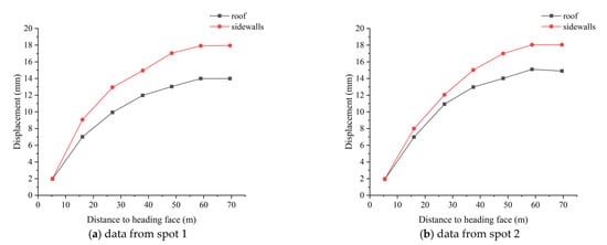
Figure 18.
Displacement variation.
7. Conclusions
A numerical study with UDEC software was conducted to study the zone damage of the deep roadway roof and investigate the mechanism of the long anchorage zone linkage technology. Furthermore, the field tests of support technology application were applied in typical roadways with different geological conditions to optimize the overall stability of surrounding rock, especially the roof control. Finally, we acquire such conclusions:
- (1)
- By building the UDEC model with trigon grid and fish language compiled damage captured function, the fractured evolution, deformation variation, and damage quantification and data analysis were analyzed during the model running. The calibrated process of input parameters guaranteed the model construction in a precise way. Based on the data of roof damage, the results show that the roof’s main trend of damage evolution after roadway excavation progressively developed upward, while there also exists minor damage in the roof’s deeper zones. The initiation and propagation from roadway roof surface fractures to deeper places can largely induce the instability of the roadway roof. The main work of this part is to partition the roadway roof in several zones and quantify the damage. Through the zone damage data analysis in each zone, the construction of anchorage zone should cover the low level of damage zone to realize the stability of roadway roof.
- (2)
- With the variation of bolt length in different models, the 2 m bolt cannot effectively prohibit fractures outside the anchorage zone. Due to the end of the 2 m bolt within the unstable fractured zone, the support system cannot perform well, and the bearing structure easily loses its anchor foundation. By increasing the bolt length to 3–5 m, the fracture range, deformation variation, and damage values all decreased based on the results of data analysis and plotted figures. Extending the length of bolts is to mobilize the rock mass in minor damaged areas and more damaged areas to form a thicker bearing structure with higher rigidity and strength and link different zones’ rock mass to participate in bearing stress together. Long anchorage zonal linkage technology has an important role in the fissure development prohibition in and outside the anchorage zone formed by the long bolts. The formation of thick anchorage zone can prohibit the development of the large crack scope in deep underground openings.
- (3)
- Based on the long anchorage zone linkage technology, the field tests were conducted in typical roadways with different geological characteristics. The application in the typical roadway roof makes the roof and sidewall deform downwards, and fracture scope develops in a small range. All field tests acquired good results on controlling fracture evolution and forming a stable bearing structure to maintain the roof stability. By modeling the controlling experience, the long anchorage zonal linkage technology can be applied to similar problems in underground opening excavation.
Author Contributions
Conceptualization, Y.W.; methodology, Y.W. and W.W.; software, Y.W.; validation, Y.W., W.W. and J.C.; formal analysis, Y.W. and N.Z.; investigation, J.C. and D.D.; data curation, Y.W.; writing—original draft preparation, Y.W.; writing—review and editing, W.W. and Y.G.; supervision, N.Z.; project administration, N.Z.; funding acquisition, N.Z. All authors have read and agreed to the published version of the manuscript.
Funding
This research was funded by [National Natural Science Foundation of China] grant number [52034007]. And The APC was funded by [National Natural Science Foundation of China].
Conflicts of Interest
The authors declare no conflict of interest.
References
- Yuan, L.; Zhang, N.; Kan, J.G.; Wang, Y. The Concept, Model and Reserve Forecast of Green Coal Resources in China. J. China Univ. Min. Technol. 2018, 47, 1–8. [Google Scholar]
- Yuan, L. Strategic Thinking of Simultaneous Exploitation of Coal and Gas in Deep Mining. J. China Coal Soc. 2016, 41, 1–6. [Google Scholar]
- Xie, H.; Zhou, H.; Xue, D.; Wang, H.; Zhang, R.; Gao, F. Research and Consideration on Deep Coal Mining and Critical Mining Depth. J. China Coal Soc. 2012, 37, 535–542. [Google Scholar]
- Zhao, B.; Li, J.; Wang, A.; Xiang, H.; Xu, F. Theoretical and Numerical Analysis of a New Energy-Absorbing Rock Bolt with Controllable Constant Resistance and Large Displacement. Tunn. Undergr. Space Technol. 2020, 106, 103581. [Google Scholar] [CrossRef]
- Zhang, N.; Han, C.L.; Xie, Z.Z. Theory of Continuous Beam Control and High Efficiency Supporting Technology in Coal Roadway. J. Min. Strat. Control. Eng. 2019, 1, 13005. [Google Scholar]
- An, Y.; Zhang, N.; Zhao, Y.; Xie, Z. Field and Numerical Investigation on Roof Failure and Fracture Control of Thick Coal Seam Roadway. Eng. Fail. Anal. 2021, 128, 105594. [Google Scholar] [CrossRef]
- Guan, K.; Zhu, W.; Yu, Q.; Cui, L.; Song, F. A Plastic-Damage Approach to the Excavation Response of a Circular Opening in Weak Rock. Tunn. Undergr. Space Technol. 2022, 126, 104538. [Google Scholar] [CrossRef]
- Kang, H.P. Research and Practice of Bolting Support Technology in Deep Coal Roadways. Coal. Min. Technol. 2008, 13, 1–5. [Google Scholar]
- Zuo, J.; Wen, J.; Liu, D. Control Theory of Uniform Strength Support in Deep Roadway. J. Min. Sci. Technol. 2021, 6, 148–159. [Google Scholar]
- Jing, H.W.; Meng, Q.B.; Zhu, J.F.; Meng, B.; Yu, L.Y. Theoretical and Technical Progress of Stability Control of Broken Rock Zone of Deep Roadway Surrounding Rock. J. Min. Saf. Eng. 2020, 37, 429–442. [Google Scholar]
- Hou, C.J.; Wang, X.Y.; Bai, J.B.; Meng, N.K.; Wu, W.D. Basic Theory and Technology Study of Stability Control for Surrounding Rock in Deep Roadway. J. China Univ. Min. Technol. 2021, 50, 1–12. [Google Scholar]
- Hou, C. Effective Approach for Surrounding Rock Control in Deep Roadway. J. China Univ. Min. Technol. 2017, 46, 467–473. [Google Scholar]
- Zhang, N.; Wang, C.; Gao, M.; Zhao, Y. Roadway Support Difficulty Classification and Controlling Techniques for Huainan Deep Coal Mining. Chin. J. Rock Mech. Eng. 2009, 28, 2421–2428. [Google Scholar]
- Wang, L.; Zhang, J. Research on Deformation Law of Surrounding Rock of In-Seam Roadway in Deep Mine and Its Support Technique. J. Shandong Univ. Sci. Technol. 2001, 20, 61–63. [Google Scholar]
- Xiao, T.Q.; Bai, J.B.; Wang, X.Y.; Chen, Y.; Yu, Y. Stability Principle and Control of Surrounding Rock in Deep Coal Roadway with Large Section and Thick Top-Coal. Rock Soil Mech. 2011, 32, 1874–1880. [Google Scholar]
- Yuan, L.; Xue, J.; Liu, Q. Surrounding Rock Stability Control Theory and Support Technique in Deep Rock Roadway for Coal Mine. J. China Coal Soc. 2011, 36, 535–543. [Google Scholar]
- Xiao, T.; Li, H. Numerical Simulation Analysis of Rock Bolt Stress in Deep Coal Roadway. Adv. Mater. Res. 2012, 619, 231–238. [Google Scholar]
- Xie, G.X.; Chang, J.C. Study of Space-Time Coupled and Integrative Supporting Method of Controlling the Minimum Deformation of Surrounding Rock in Deep Mine Roadway. J. China Univ. Min. Technol. 2013, 42, 183–187. [Google Scholar]
- Xie, S.; Li, E.; Li, S.; Wang, J.; He, C.; Yang, Y. Surrounding Rock Control Mechanism of Deep Coal Roadways and its Application. Int. J. Min. Sci. Technol. 2015, 25, 429–434. [Google Scholar] [CrossRef]
- Wang, Q.; Jiang, B.; Pan, R.; Li, S.; He, M.; Sun, H.; Qin, Q.; Yu, H.; Luan, Y. Failure Mechanism of Surrounding Rock with High Stress and Confined Concrete Support System. Int. J. Min. Sci. Technol. 2018, 102, 89–100. [Google Scholar] [CrossRef]
- Xie, Z.; Zhang, N.; Feng, X.; Liang, D.; Wei, Q.; Weng, M. Investigation on the Evolution and Control of Surrounding Rock Fracture under Different Supporting Conditions in Deep Roadway during Excavation Period. Int. J. Rock Mech. Min. Sci. 2019, 123, 104122. [Google Scholar] [CrossRef]
- Wang, D.; Jiang, Y.; Sun, X.; Luan, H.; Zhang, H. Nonlinear Large Deformation Mechanism and Stability Control of Deep Soft Rock Roadway: A Case Study in China. Sustainability 2019, 11, 6243. [Google Scholar] [CrossRef] [Green Version]
- Yang, H.; Han, C.; Zhang, N.; Sun, Y.; Pan, D.; Sun, C. Long High-Performance Sustainable Bolt Technology for the Deep Coal Roadway Roof: A Case Study. Sustainability 2020, 12, 1375. [Google Scholar] [CrossRef] [Green Version]
- Zhao, C.; Li, Y.; Liu, G.; Meng, X. Mechanism Analysis and Control Technology of Surrounding Rock Failure in Deep Soft Rock Roadway. Eng. Fail. Anal. 2020, 115, 104611. [Google Scholar] [CrossRef]
- Zhu, C.; Yuan, Y.; Wang, W.; Chen, Z.; Wang, S.; Zhong, H. Research on the “Three Shells” Cooperative Support Technology of Large-Section Chambers in Deep Mines. Int. J. Min. Sci. Technol. 2021, 31, 665–680. [Google Scholar] [CrossRef]
- Sun, Y.; Li, G.; Zhang, J.; Qian, D. Experimental and Numerical Investigation on a Novel Support System for Controlling Roadway Deformation in Underground Coal Mines. Energy Sci. Eng. 2020, 8, 490–500. [Google Scholar] [CrossRef] [Green Version]
- Wu, W.; Bai, J.; Wang, X.; Yan, S.; Wu, S. Numerical Study of Failure Mechanisms and Control Techniques for a Gob-Side Yield Pillar in the Sijiazhuang Coal Mine, China. Rock Mech. Rock Eng. 2019, 52, 1231–1245. [Google Scholar] [CrossRef]
- Yang, S.; Chen, M.; Jing, H.; Chen, K.; Meng, B. A Case Study on Large Deformation Failure Mechanism of Deep Soft Rock Roadway in Xin’An Coal Mine, China. Eng. Geol. 2017, 217, 89–101. [Google Scholar] [CrossRef]
- Zhang, L.; Einstein, H.H. Using RQD to Estimate the Deformation Modulus of Rock Masses. Int. J. Rock Mech. Min. Sci. 2004, 41, 337–341. [Google Scholar] [CrossRef]
- Singh, M.; Seshagiri, R.K. Empirical Methods to Estimate the Strength of Jointed Rock Masses. Eng. Geol. 2005, 77, 127–137. [Google Scholar] [CrossRef]
- Gao, F.Q. Simulation of Failure Mechanisms Around Underground Coal Mine Openings Using Discrete Element Modelling. Ph.D. Thesis, Simon Fraster University, Burnaby, BC, Canada, 2013. [Google Scholar]
- Gao, F.; Stead, D.; Kang, H. Numerical Simulation of Squeezing Failure in a Coal Mine Roadway due to Mining-Induced Stresses. Rock Mech. Rock Eng. 2015, 48, 1635–1645. [Google Scholar] [CrossRef]
Publisher’s Note: MDPI stays neutral with regard to jurisdictional claims in published maps and institutional affiliations. |
© 2022 by the authors. Licensee MDPI, Basel, Switzerland. This article is an open access article distributed under the terms and conditions of the Creative Commons Attribution (CC BY) license (https://creativecommons.org/licenses/by/4.0/).