
Behavior of RC Beam–Column Joints Strengthened with Modified Reinforcement Techniques

 , , ,
, , ,  ,
,  and
and
Abstract
:1. Introduction
1.1. Interior Beam–Column Joint
1.2. Corner RC Beam–Column Joint
- Around the corner, the tension steel is persistent, i.e., there is no lapping in the joint;
- The tension bars have to be curved into a radius that prevents the bars from bending or breaking. Nominal transverse bars are placed beneath the bent bars;
- Only a certain quantity of tension reinforcement is allowed [32].
2. Detailing Recommendations for Joints
- Anchorage: Due to loss of bond at the inner face of an exterior joint, the development length of the beam reinforcement should be computed from the beginning of the 90° bend, rather than the face of the column. In wide columns, any portion of the beam bars within the outer third of the column could be considered for the computed development length. For shallow columns, the use of stub beams will be imperative. A large-diameter bearing bar fitted along the 90° bend of the beam bars should be beneficial in distributing bearing stresses. In deep columns, and whenever straight beam bars are preferred, mechanical anchorage could be advantageous. Joint ties should be so arranged that the critical outer-column bars and the bent-down portions of the bars are held against the core of the joint;
- Shear Strength: When the computed axial compression on the column is small, the contribution of the concrete shear resistance should be ignored, and shear reinforcement for the entire joint-shearing force should be provided. In exterior joints, only the ties that are situated in the outer two-thirds of the length of the potential diagonal failure crack, which runs from corner to corner of the joint, should be considered to be effective. The joint shear to be carried by the ties is calculated as:where Vs = joint shear carried by the ties, Av = the total area of tie legs in a pair that makes up one layer of shear reinforcement, and d = the beam’s effective depth.For preventing the excessive diagonal compression of core concrete, an upper bound for joint shear, usually stated as a nominal shearing force, must be imposed. The value between 10√f′c and 11.5√f′c (psi) is recommended for beams;
- Confinement: Horizontal tie legs are ineffectual for providing constraint against the concrete core volumetric expansion, while shear reinforcement restricts only the joint’s corner regions. As a result, extra confining bars at right angles to the shear reinforcement are required. The distance between these bars should not exceed 150 mm.
- Cl-7.4.1 Special confining reinforcement (lo) (unless shear strength considerations demand a larger amount of transverse reinforcement) should be provided across a span of every joint face, towards the mid-span, and on each side of any area where flexural yielding may occur owing to earthquake pressures. The length ‘lo’ should not be less than (a) the member’s greater lateral dimension at the section where yielding occurs, (b) 1/6 of the member’s clear span, and (c) 450 mm;
- Cl-8.1 Unless the joint is confined, the special confining reinforcement necessary at the column end must also be carried through the joint;
- Cl-8.2 A connection with beams framing all vertical sides, with each beam having a width of at least 3/4 of the column width, may be given half of the special restricting reinforcement needed at the column’s end. The hoops’ spacing shall not be more than 150 mm;
- In the joint region, diagonal cracking and concrete crushing can be managed by providing large column dimensions and densely packed closed-loop steel ties surrounding the column bars. The ties help resist the shear stress and hold the concrete in the joint, hence preventing concrete cracking and crushing;
- The transverse loop should continue around the joint region around the column bars. This is cultivated by setting up the instance of all bar supports (both longitudinal bars and stirrups) on top of the shaft formwork at that level and lower into the case;
- The building columns in seismic zones III, IV, and V are to be at least 300-mm wide in each direction of the cross-section when the column support beams are longer than 5 m or when these columns are taller than 4 m between floors;
- A piece of the top pillar bar is consolidated in the segment that is projected up to the soffit of the bar, and a piece of it overhangs in segments with short widths and huge-breadth shaft bars;
- Beam bars may not reach past the soffit of the pillar if the section width is extensive;
- Interior joints need the top and base bars to go through the intersection without being cut, and these bars should be set inside the section bars without any twists;
- The American Concrete Institute suggests a segment width that is no less than multiple times the distance across the longest longitudinal bar in the adjoining pillar.
3. Experimental Program
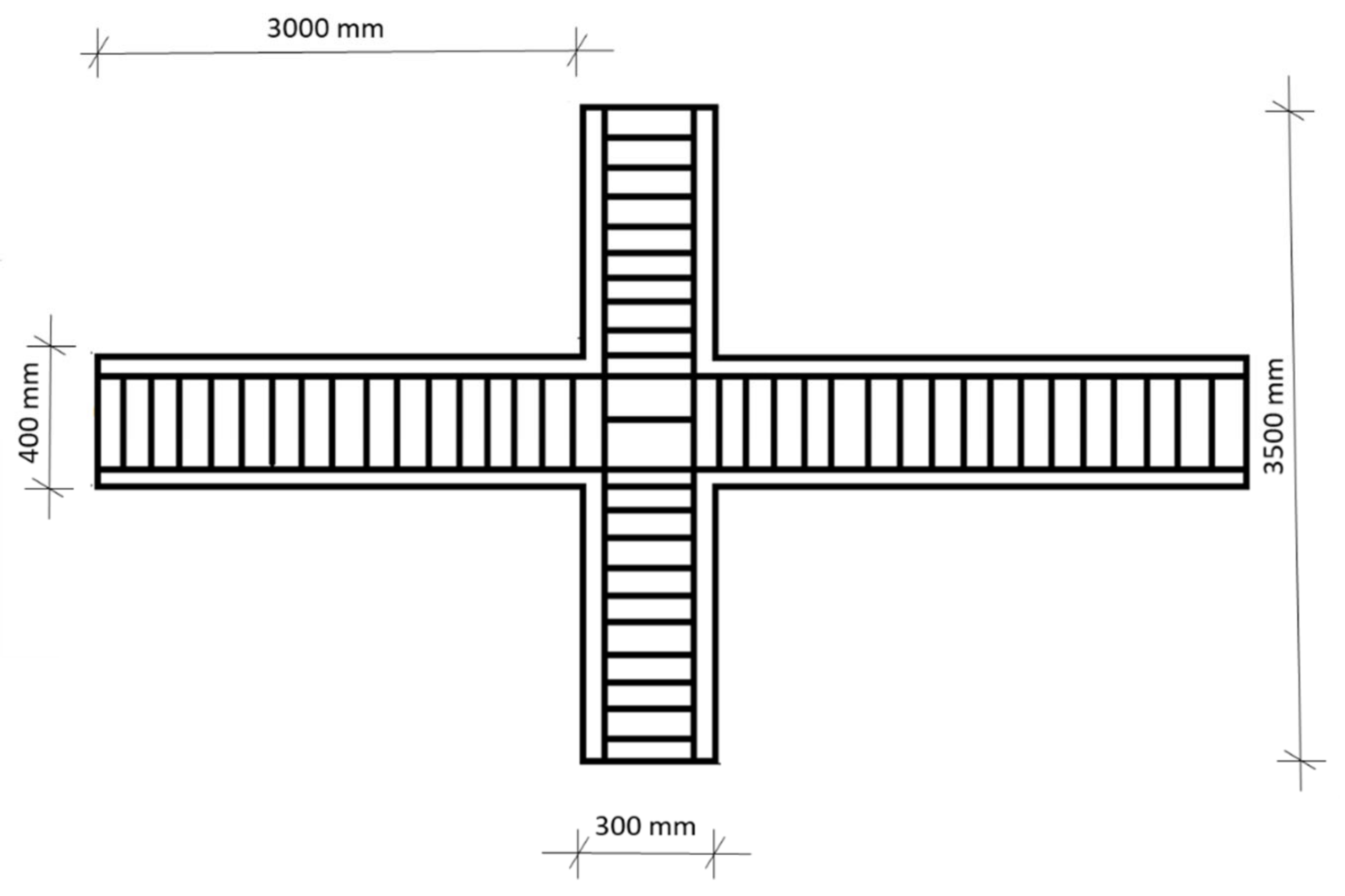
Details of Specimens
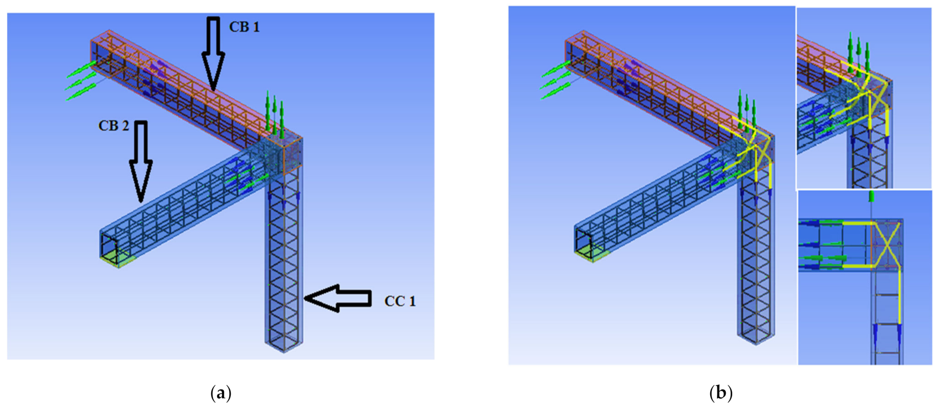
4. Numerical Modeling and Analysis of Beam–Column Joints
5. Results Obtained by Numerical Modeling
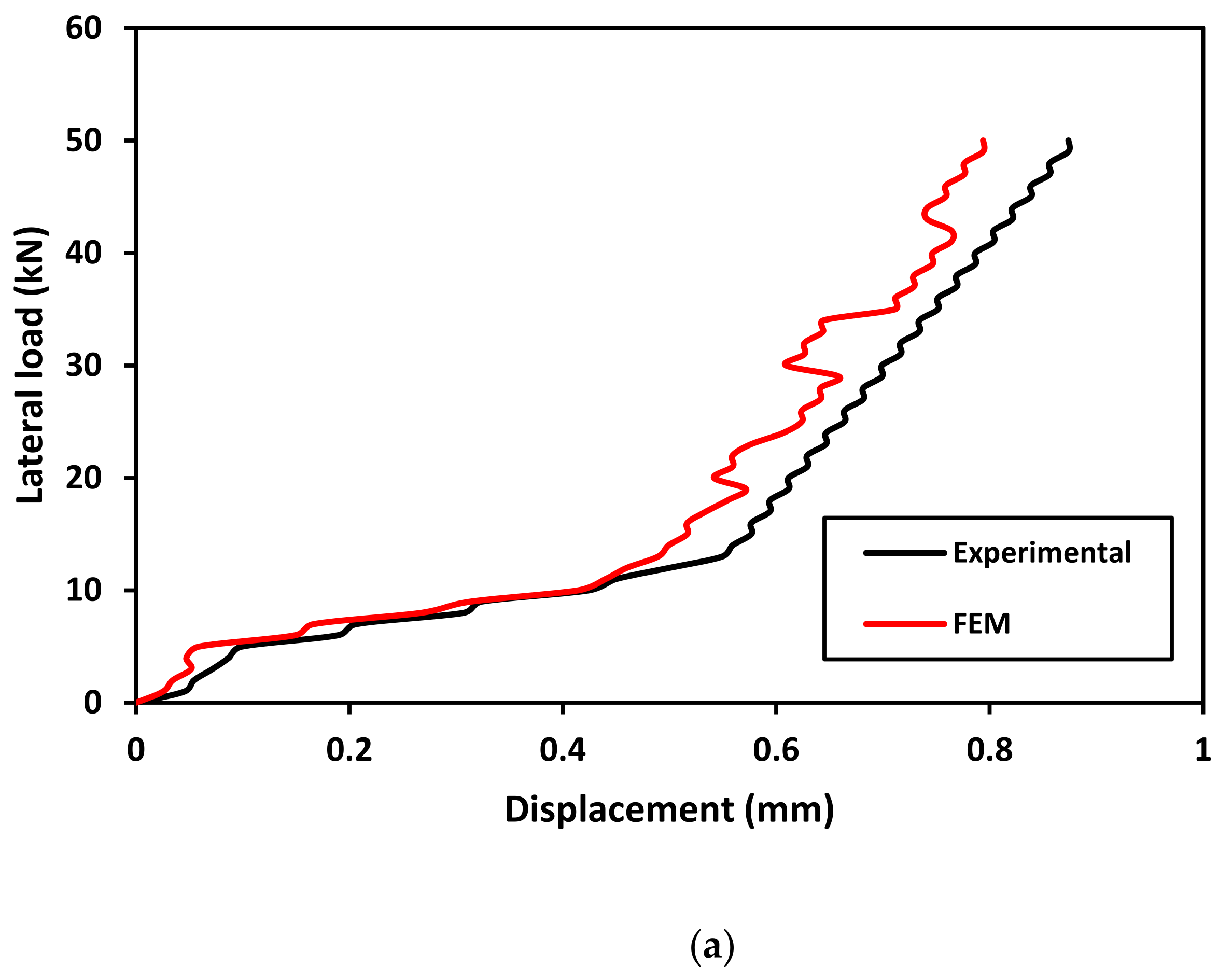
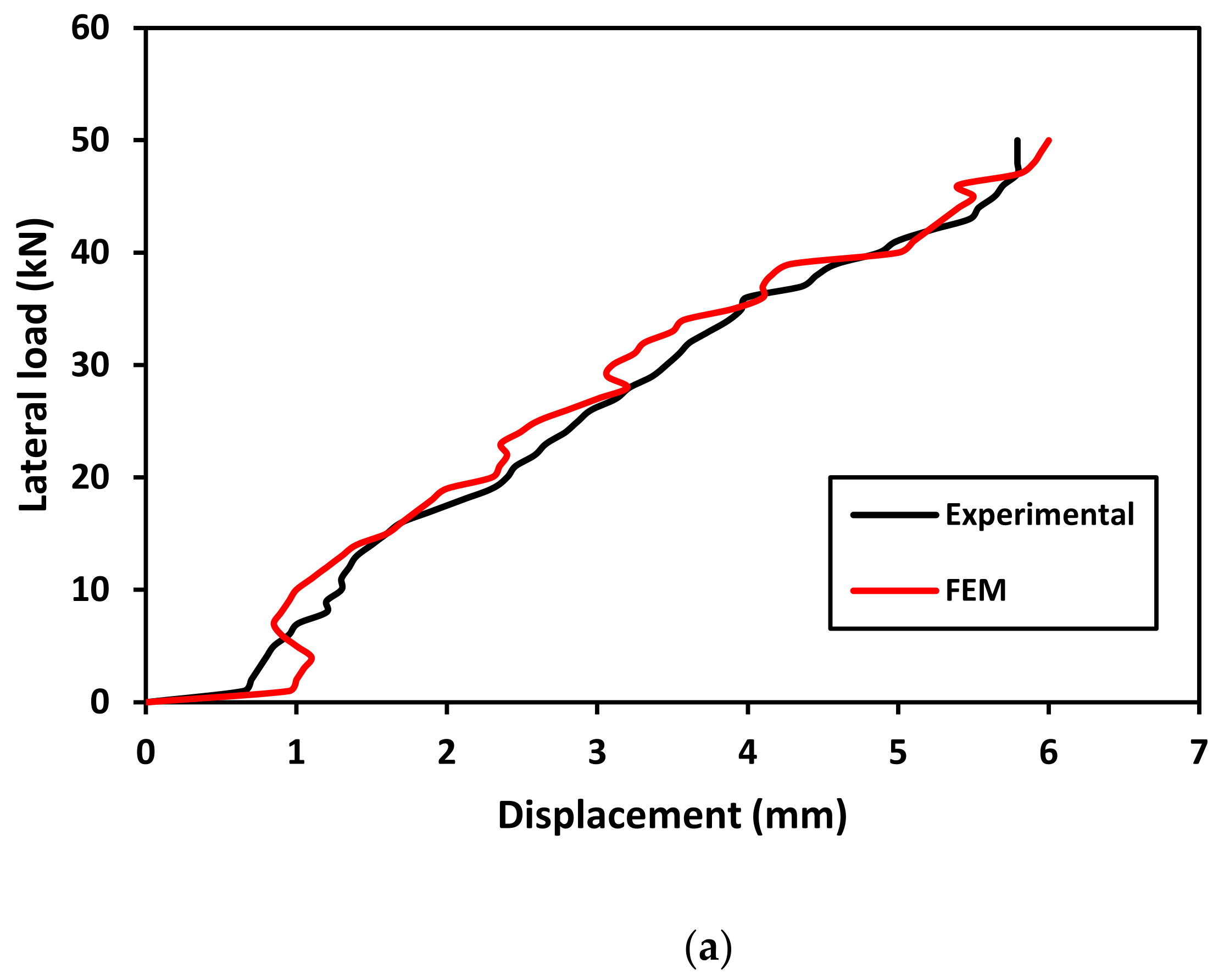
5.1. Validation of Results
5.2. Load-Displacement Behaviour for Beam–Column Joints
6. Results and Discussions
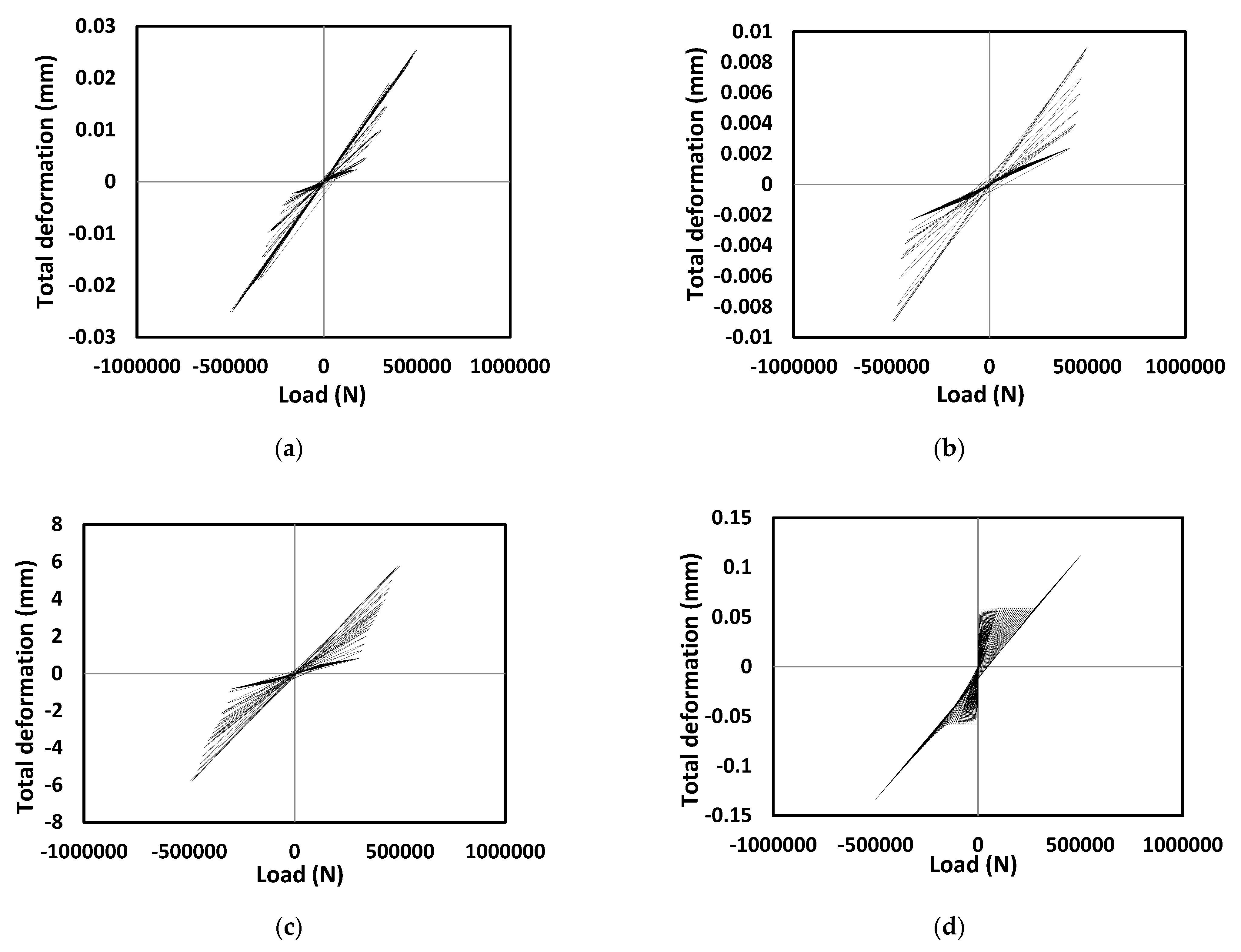
6.1. Hysteretic Behavior of Corner and Interior Beam–Column Junctions
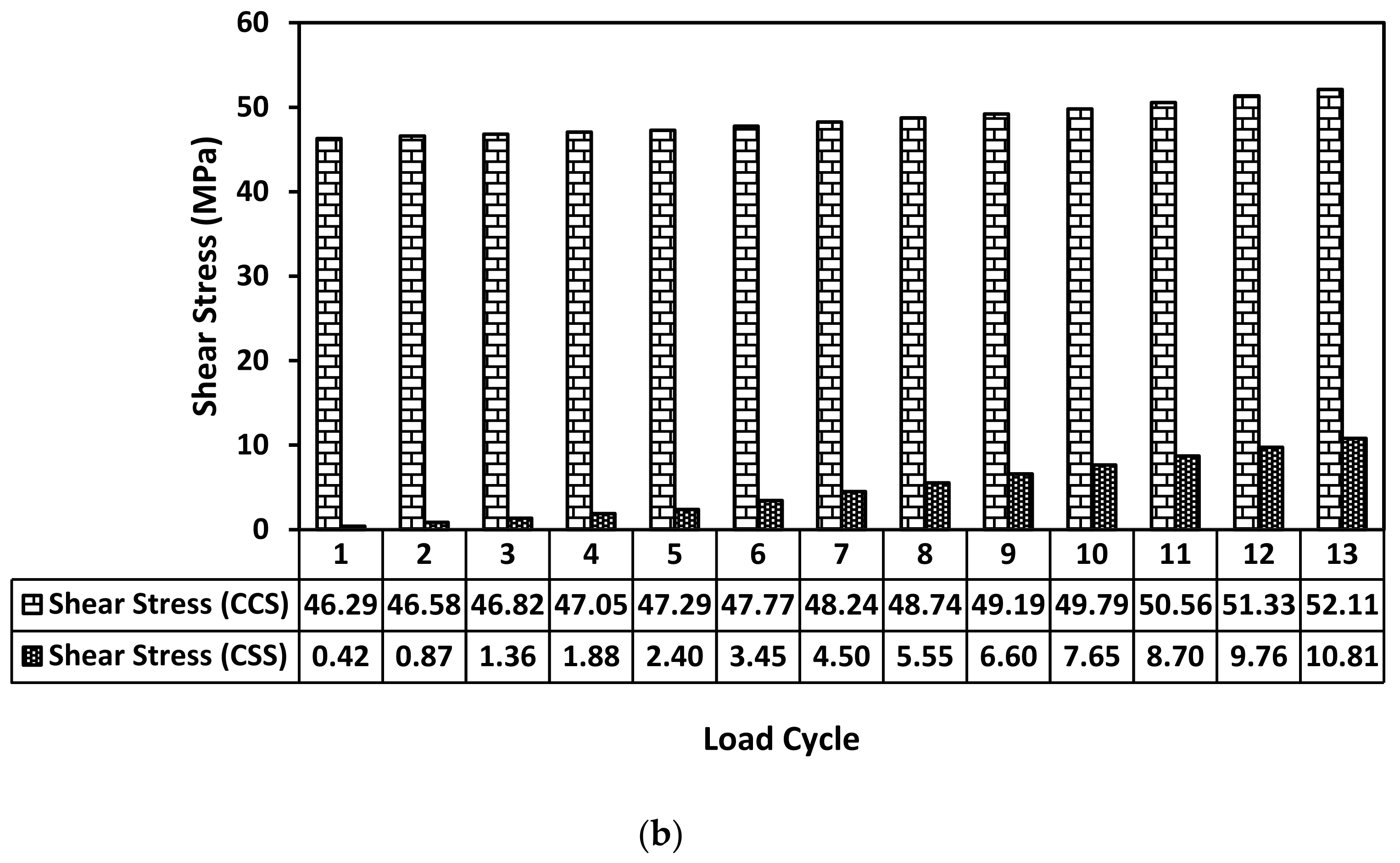
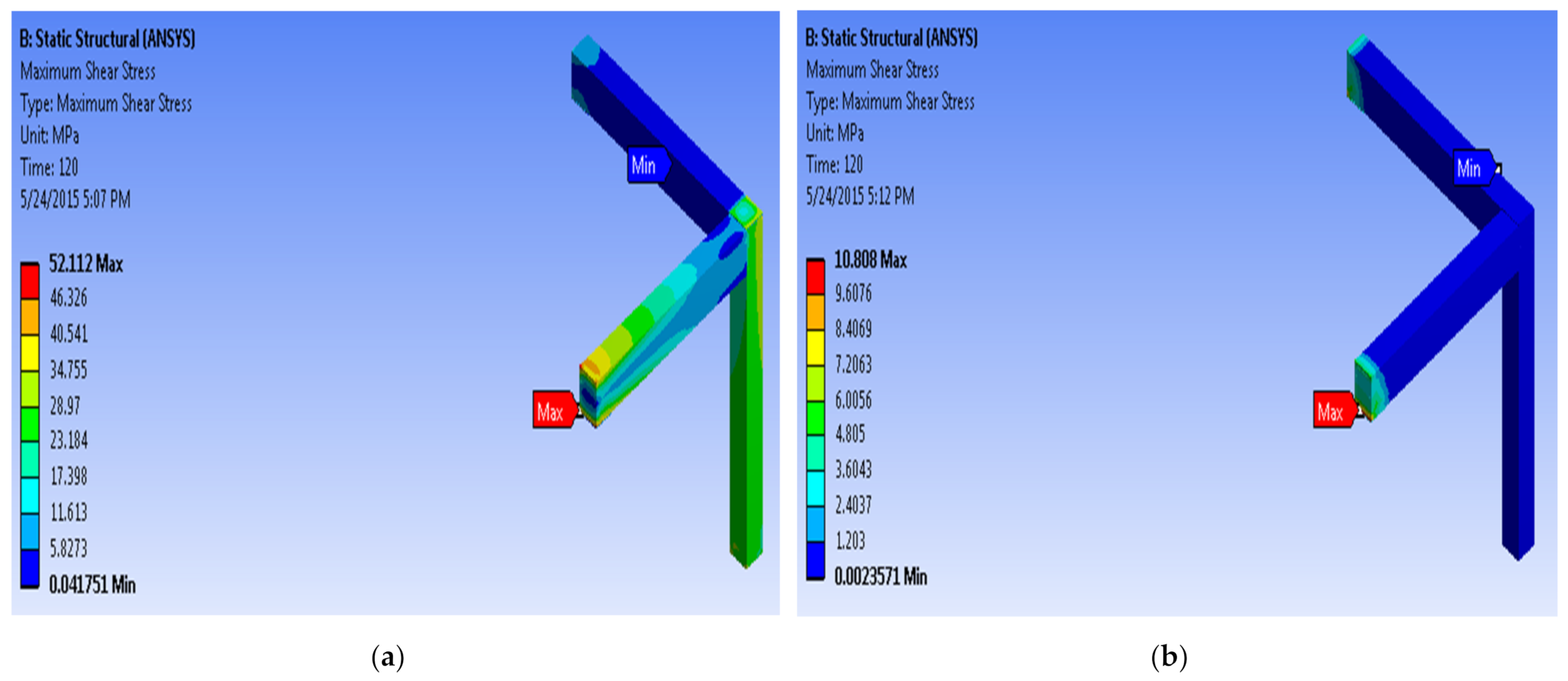
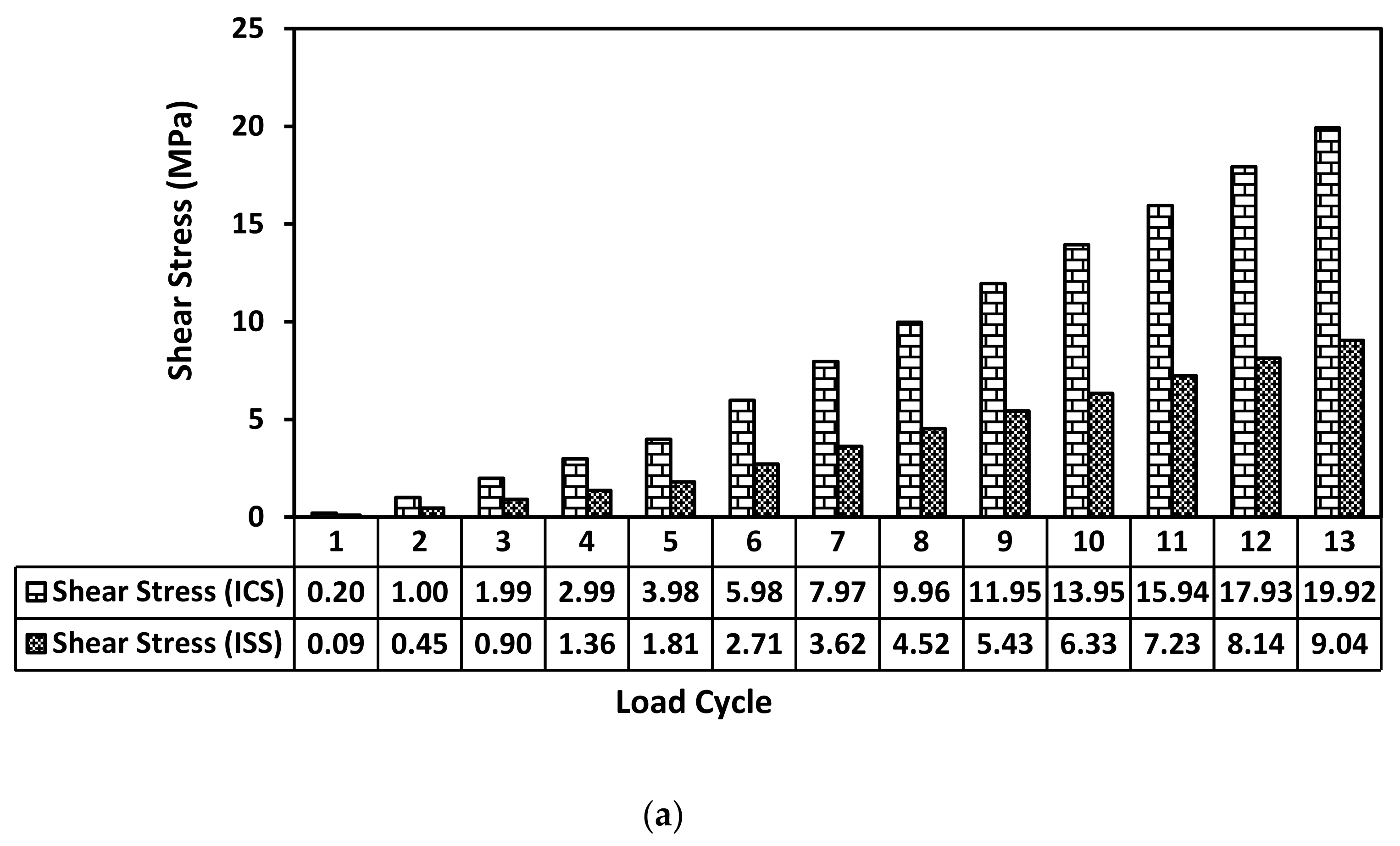
6.2. Shear Stress vs. Loading Cycle Behavior of Joints
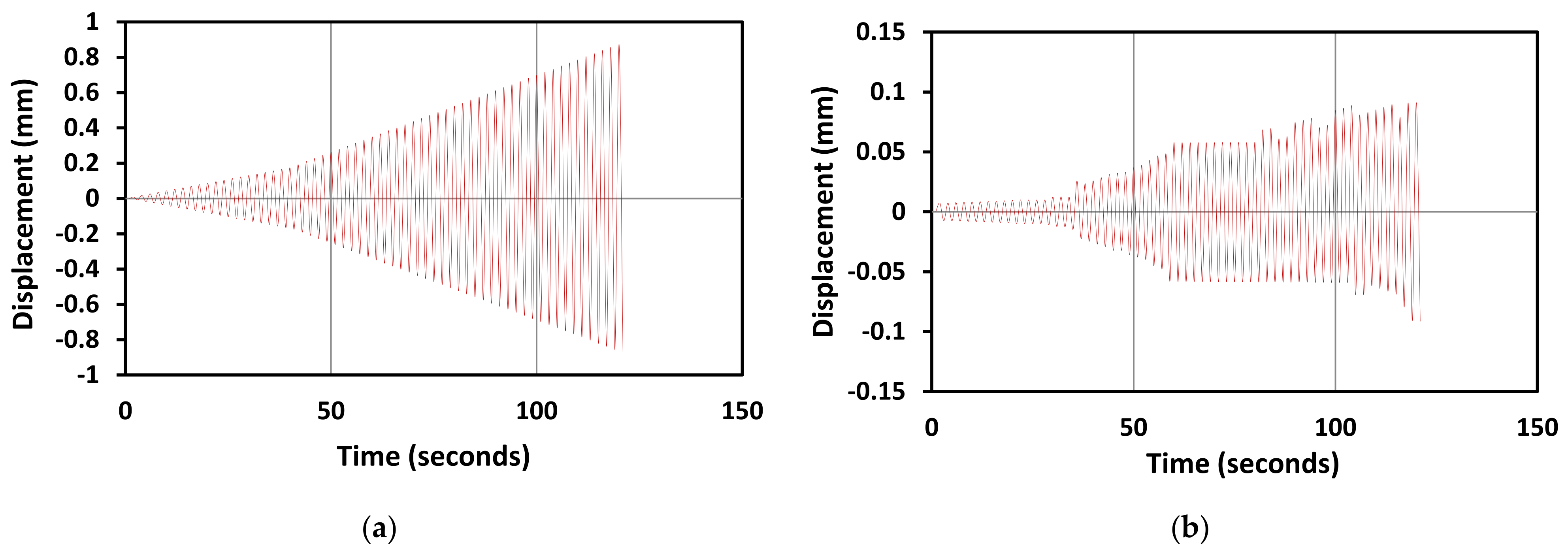
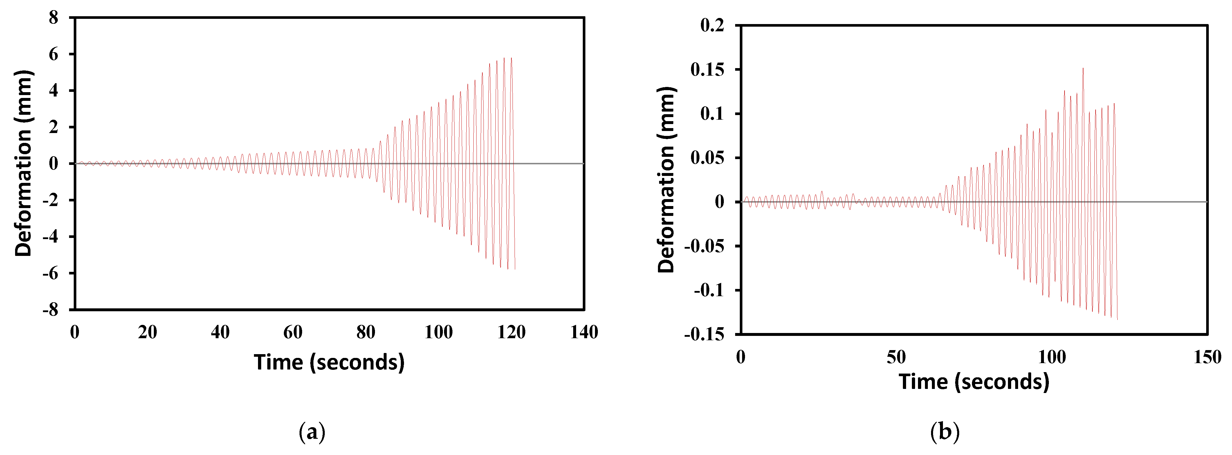
6.3. Displacement Time History Curve for Beam–Column Joints
7. Conclusions
- Based on the present research, the most critical parameters influencing joint shear capacity are the stirrups quantity, the aspect ratio of the joint, the beam longitudinal reinforcement anchorage, and the compressive strength of concrete;
- The results obtained through the experimental studies were validated with numerical analysis in terms of load-deformation behavior, and the numerical results were in great concurrence with the experimental data;
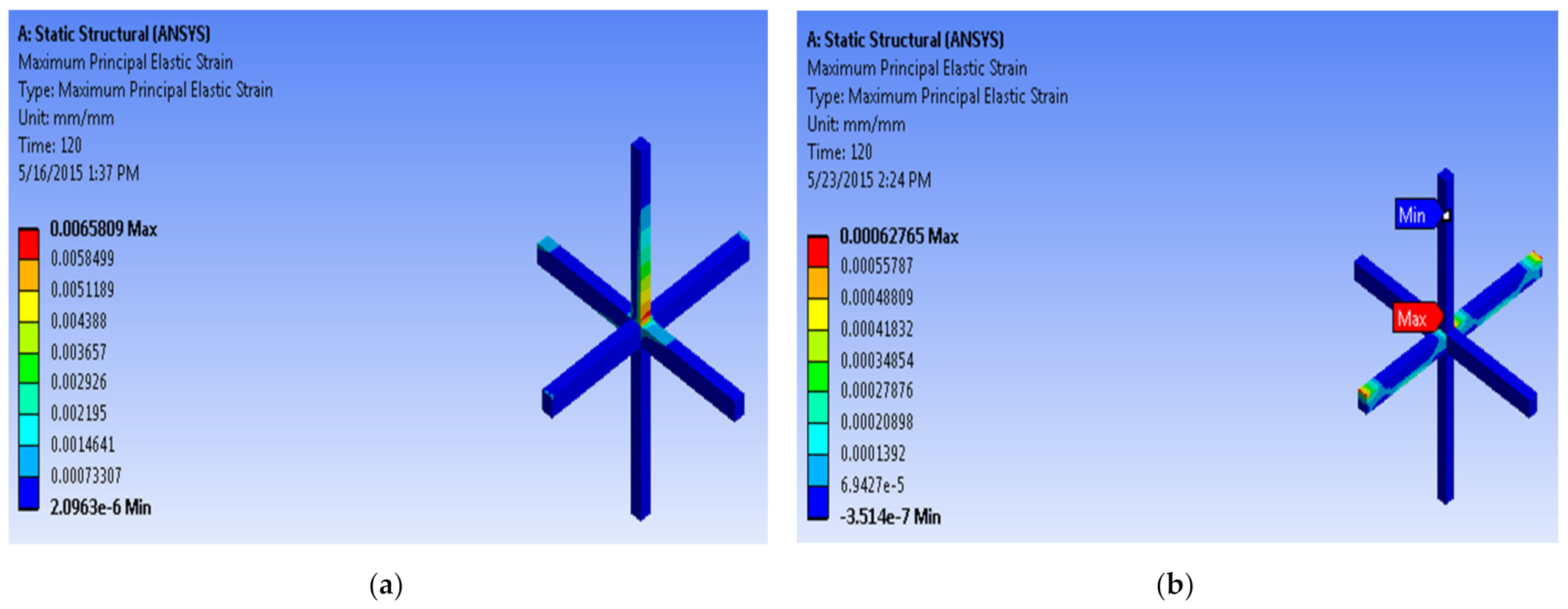
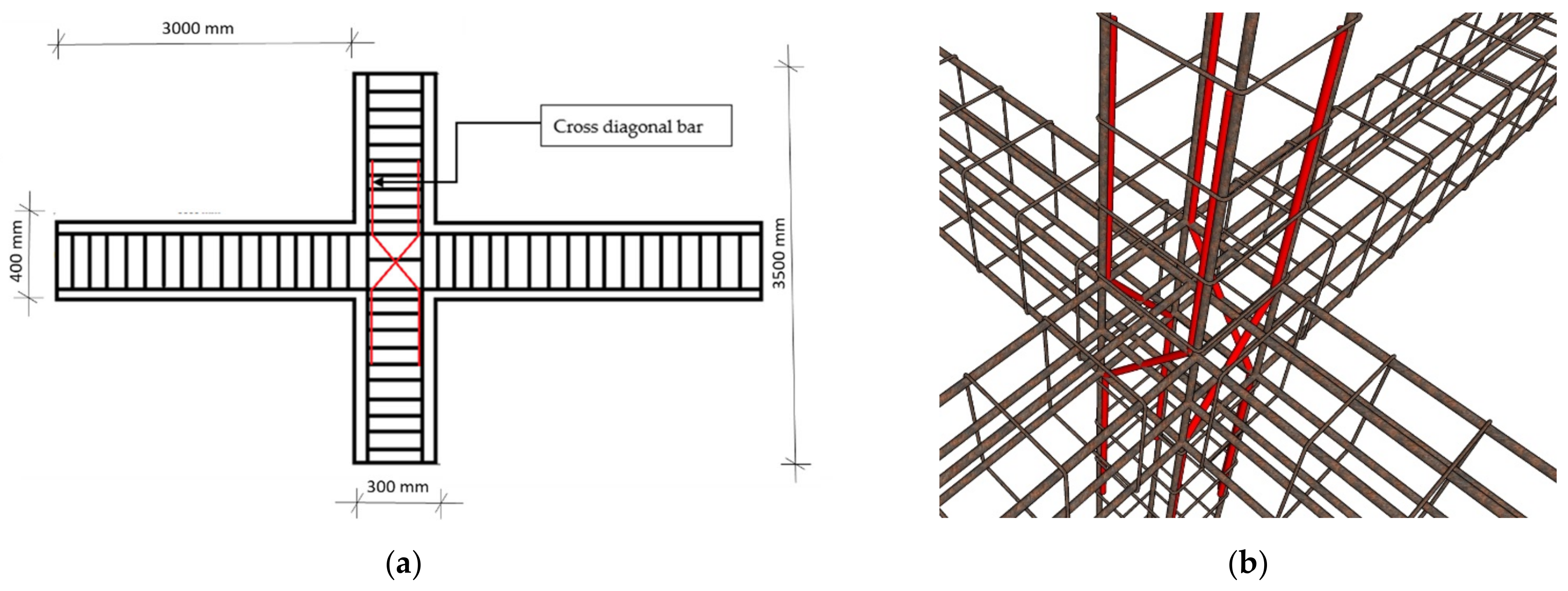
- The findings of the finite-element model are compared to the controlled and strengthened specimens, and it is discovered that adding diagonal cross bars (modified reinforcing techniques) to beam–column joints exposed to cyclic loads enhances their performance more than using a controlled specimen in both interior and corner beam–column joints;
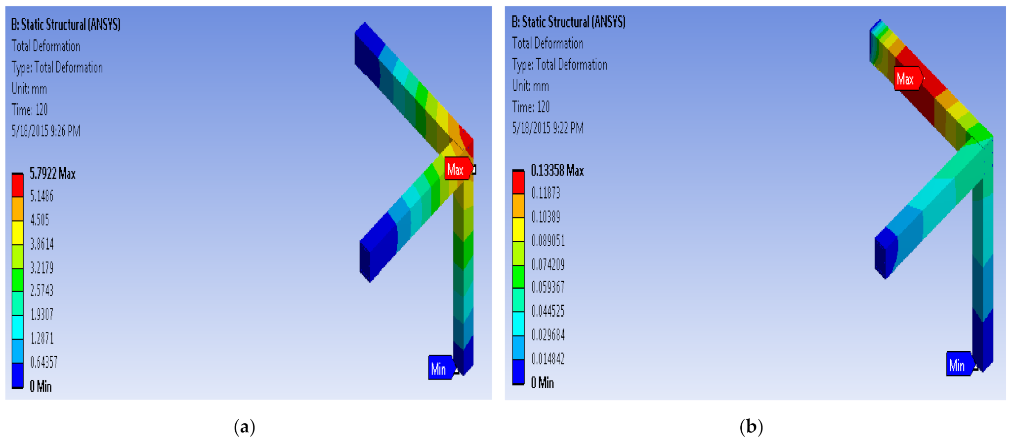
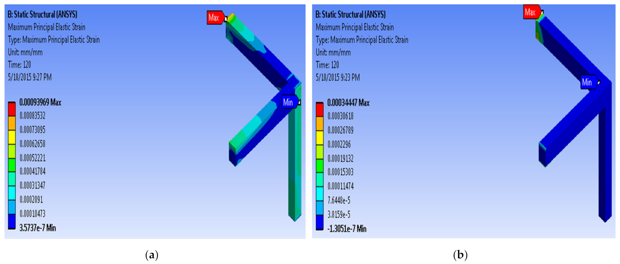
- The corner beam–column joint models for the controlled and strengthened specimens are analyzed for similar loadings with different reinforcement arrangements. The larger deformations and stresses, which are reported in the controlled specimen, are reduced in the strengthened specimens after employing modified reinforcement techniques;
- When the controlled and strengthened specimens for the interior beam–column joint are analyzed, it is found that the maximum stress and deformation caused in the joint are controlled by using additional diagonal cross bars at the joint region;
- Modified reinforcement techniques with the diagonal cross bar at the joint region is a viable option for enhancing the shear capacity of beam–column joints. The diagonal cross bars help to create an extra shear-transfer mechanism;
- A beam–column junction loses structural efficiency when it is exposed to large lateral stresses, such as high winds. Therefore, against such stresses, the specimens with a diagonal crossbar at the junction work best;
- In both upward- and downward-load situations, the introduction of cross-inclined bars at the junction area of a strengthened corner and an interior beam–column junction maximizes the joint’s stiffness, enhances its load-carrying capacity, as well as its ductility, according to an improved reinforcing approach.
Author Contributions
Funding
Institutional Review Board Statement
Informed Consent Statement
Data Availability Statement
Conflicts of Interest
Abbreviations
| MRT | Modified reinforcement technique |
| ICS | Controlled specimen of interior joint without MRT |
| CCS | Controlled specimen of corner joint without MRT |
| ISS | Strengthened specimen of interior joint with MRT |
| CSS | Strengthened specimen of corner joint with MRT |
References
- Bossio, A.; Fabbrocino, F.; Lignola, G.P.; Prota, A.; Manfredi, G. Simplified Model for Strengthening Design of Beam–Column Internal Joints in Reinforced Concrete Frames. Polymers 2015, 7, 1732–1754. [Google Scholar] [CrossRef]
- Calvi, G.M.; Magenes, G.; Pampanin, S. Relevance of beam-column joint damage and collapse in rc frame assessment. J. Earthq. Eng. 2002, 6, 75–100. [Google Scholar] [CrossRef]
- Park, R. A summary of results of simulated seismic load tests on reinforced concrete beam-column joints, beams and columns with substandard reinforcing details. J. Earthq. Eng. 2002, 6, 147–174. [Google Scholar] [CrossRef]
- Alsayed, S.H.; Al-Salloum, Y.A.; Almusallam, T.H.; Siddiqui, N.A. Seismic Response of FRP-Upgraded Exterior RC Beam-Column Joints. J. Compos. Constr. 2010, 14, 195–208. [Google Scholar] [CrossRef]
- Alhaddad, M.S.; Siddiqui, N.A.; Abadel, A.A.; Alsayed, S.H. Numerical Investigations on the seismic Behavior of FRP and TRM Upgraded RC Exterior Beam-column Joints. J. Compos. Constr. 2012, 16, 308–321. [Google Scholar] [CrossRef]
- Rossetto, T.; Elnashai, A. Derivation of vulnerability functions for European-type RC structures based on observational data. Eng. Struct. 2003, 25, 1241–1263. [Google Scholar] [CrossRef]
- Ricci, P.; De Luca, F.; Verderame, G.M. 6th April 2009 L’Aquila earthquake, Italy: Reinforced concrete building performance. Bull. Earthq. Eng. 2010, 9, 285–305. [Google Scholar] [CrossRef] [Green Version]
- Pejovic, J.; Stepinac, M.; Serdar, N.; Jevric, M. Improvement of Eurocode 8 Seismic Design Envelope for Bending Moments in RC Walls of High-rise Buildings. J. Earthq. Eng. 2020, 1–25. [Google Scholar] [CrossRef]
- Kišiček, T.; Stepinac, M.; Renić, T.; Hafner, I.; Lulić, L. Strengthening of masonry walls with FRP or TRM. J. Croat. Assoc. Civ. Eng. 2020, 72, 937–953. [Google Scholar] [CrossRef]
- Bindhu, K.R.; Jaya, K.P. Strength and Behavior of Exterior Beam Column Joints with Diagonal Cross Bracing Bars. Asian J. Civil. Eng. 2010, 11, 397–410. [Google Scholar]
- Ramírez-Herrera, M.-T.; Romero, D.; Corona, N.; Nava, H.; Torija, H.; Maguey, F.H. The 23 June 2020 MW 7.4 la crucecita, Oaxaca, Mexico earthquake and tsunami: A rapid response field survey during COVID-19 crisis. Seismol. Res. Lett. 2020, 92, 26–37. [Google Scholar] [CrossRef]
- Cetin, K.O.; Mylonakis, G.; Sextos, A.; Stewart, J.P. Reconnaissance of 2020 M 7.0 Samos Island (Aegean Sea) earthquake. Bull. Earthq. Eng. 2021, 1–6. [Google Scholar] [CrossRef]
- Stepinac, M.; Lourenço, P.B.; Atalić, J.; Kišiček, T.; Uroš, M.; Baniček, M.; Novak, M.Š. Damage classification of residential buildings in historical downtown after the ML5.5 earthquake in Zagreb, Croatia in 2020. Int. J. Disaster Risk Reduct. 2021, 56, 102140. [Google Scholar] [CrossRef]
- Almusallam, T.H.; Al-Salloum, Y.A. Seismic response of interior RC beam-column joints upgraded with FRP sheets. II: Analy-sis and Parametric Study. J. Compos. Constr. 2007, 11, 590–600. [Google Scholar] [CrossRef]
- Dabiri, H.; Kaviani, A.; Kheyroddin, A. Influence of reinforcement on the performance of non-seismically detailed RC beam-column joints. J. Build. Eng. 2020, 31, 101333. [Google Scholar] [CrossRef]
- Dabiri, H.; Kheyroddin, A.; Kaviani, A. A Numerical Study on the Seismic Response of RC Wide Column–Beam Joints. Int. J. Civ. Eng. 2018, 17, 377–395. [Google Scholar] [CrossRef]
- Tsonos, A.-D.; Kalogeropoulos, G.; Iakovidis, P.; Bezas, M.-Z.; Koumtzis, M. Seismic Performance of RC Beam–Column Joints Designed According to Older and Modern Codes: An Attempt to Reduce Conventional Reinforcement Using Steel Fiber Reinforced Concrete. Fibers 2021, 9, 45. [Google Scholar] [CrossRef]
- Hanif, F.; Kanakubo, T. Shear Performance of Fiber-Reinforced Cementitious Composites Beam-Column Joint Using Various Fibers. J. Civ. Eng. Forum 2017, 3, 383. [Google Scholar] [CrossRef] [Green Version]
- Li, X.; Li, Y.; Yan, M.; Meng, W.; Lu, X.; Chen, K.; Bao, Y. Cyclic behavior of joints assembled using prefabricated beams and columns with Engineered Cementitious Composite (ECC). Eng. Struct. 2021, 247, 113115. [Google Scholar] [CrossRef]
- Oinam, R.M.; Kumar, P.C.A.; Sahoo, D.R. Cyclic performance of steel fiber-reinforced concrete exterior beam-column joints. Earthq. Struct. 2019, 16, 533–546. [Google Scholar]
- Annadurai, A.; Ravichandran, A. Seismic Behavior of Beam–Column Joint Using Hybrid Fiber Reinforced High-Strength Concrete. Iran. J. Sci. Technol. Trans. Civ. Eng. 2018, 42, 275–286. [Google Scholar] [CrossRef]
- IS 13920:1993; Indian Standard Code on Criteria for Earthquake Resistant Design of Structures. Bureau of Indian Standards: New Delhi, India, 2002.
- ACI Committee 318; Building Code Requirements for Structural Concrete. American Concrete Institute: Farmington Hills, MI, USA, 2005.
- Zainal, S.M.I.S.; Hejazi, F.; Rashid, R.S.M. Enhancing the Performance of Knee Beam–Column Joint Using Hybrid Fibers Reinforced Concrete. Int. J. Concr. Struct. Mater. 2021, 15, 1–28. [Google Scholar] [CrossRef]
- Dehghani, A.; Mozafari, A.R.; Aslani, F. Evaluation of the efficacy of using engineered cementitious composites in RC beam-column joints. Structures 2020, 27, 151–162. [Google Scholar] [CrossRef]
- Yuan, F.; Pan, J.; Xu, Z.; Leung, C.K.Y. A comparison of engineered cementitious composites versus normal concrete in beam-column joints under reversed cyclic loading. Mater. Struct. 2012, 46, 145–159. [Google Scholar] [CrossRef]
- Alwash, N.A.; Kadhum, M.M.; Mahdi, A.M. Rehabilitation of Corrosion-Defected RC Beam-Column Members Using Patch Repair Technique. Buildings 2019, 9, 120. [Google Scholar] [CrossRef] [Green Version]
- Bossio, A.; Fabbrocino, F.; Monetta, T.; Lignola, G.P.; Prota, A.; Manfredi, G.; Bellucci, F. Corrosion effects on seismic capacity of reinforced concrete structures. Corros. Rev. 2019, 37, 45–56. [Google Scholar] [CrossRef]
- Santarsiero, G.; Manfredi, V.; Masi, A. Numerical Evaluation of the Steel Plate Energy Absorption Device (SPEAD) for Seismic Strengthening of RC Frame Structures. Int. J. Civ. Eng. 2020, 18, 835–850. [Google Scholar] [CrossRef]
- Lowes, L.N.; Altoontash, A. Modeling Reinforced-Concrete Beam-Column Joints Subjected to Cyclic Loading. J. Struct. Eng. 2003, 129, 1686–1697. [Google Scholar] [CrossRef]
- Brooke, N.J.; Ingham, J.M. Seismic Design Criteria for Reinforcement Anchorages at Interior RC Beam-Column Joints. ASCE 2013, 139, 1895–1905. [Google Scholar] [CrossRef]
- Palermo, D.; Vecchio, F.J. Compression field modeling of reinforced concrete subjected to reversed loading: Formulation. ACI Struct. J. 2003, 100, 2–234. [Google Scholar]
- Rajagopal, P.S.S.; Thomas, H. Seismic behaviour evaluation of exterior beam-column joints with headed or hooked bars using nonlinear finite element analysis. Earthq. Struct. 2014, 7, 861–875. [Google Scholar] [CrossRef]
- Park, S.; Mosalam, K.M. Experimental Investigation of Nonductile RC Corner Beam-Column Joints with Floor Slabs. J. Struct. Eng. 2013, 139, 1–14. [Google Scholar] [CrossRef]
- Ramin, K.; Fereidoonfar, M. Finite Element Modeling and Nonlinear Analysis for Seismic Assessment of Off-Diagonal Steel Braced RC Frame. Int. J. Concr. Struct. Mater. 2015, 9, 89–118. [Google Scholar] [CrossRef] [Green Version]
- IS 456:2000; Indian Standard Code on Plain and Reinforced Concrete. Bureau of Indian Standards: New Delhi, India, 2000.
- ANSYS. ANSYS Manual; ANSYS INC: Canonsburg, PA, USA, 2009. [Google Scholar]
- Alsayed, S.H.; Almusallam, T.H.; Al-Salloum, Y.A.; Siddiqui, N.A. Seismic Rehabilitation of Corner RC Beam-Column Joints Using CFRP Composites. J. Compos. Constr. 2010, 14, 681–692. [Google Scholar] [CrossRef]
- Feng, J.; Wang, S.; Meloni, M.; Zhang, Q.; Yang, J.; Cai, J. Seismic Behavior of RC Beam Column Joints with 600 MPa High Strength Steel Bars. Appl. Sci. 2020, 10, 4684. [Google Scholar] [CrossRef]
- Santarsiero, G.; Masi, A. Seismic Upgrading of RC Wide Beam–Column Joints Using Steel Jackets. Buildings 2020, 10, 203. [Google Scholar] [CrossRef]
- Shang, X.-Y.; Yu, J.-T.; Li, L.-Z.; Lu, Z.-D. Strengthening of RC Structures by Using Engineered Cementitious Composites: A Review. Sustainability 2019, 11, 3384. [Google Scholar] [CrossRef] [Green Version]
- Golias, E.; Zapris, A.G.; Kytinou, V.K.; Osman, M.; Koumtzis, M.; Siapera, D.; Chalioris, C.E.; Karayannis, C.G. Application of X-Shaped CFRP Ropes for Structural Upgrading of Reinforced Concrete Beam–Column Joints under Cyclic Loading–Experimental Study. Fibers 2021, 9, 42. [Google Scholar] [CrossRef]
- Veismoradi, S.; Yousef-Beik, S.M.M.; Zarnani, P.; Quenneville, P. Seismic strengthening of deficient RC frames using self-centering friction haunches. Eng. Struct. 2021, 248, 113261. [Google Scholar] [CrossRef]
- Ganasan, R.; Tan, C.G.; Ibrahim, Z.; Nazri, F.M.; Sherif, M.M.; El-Shafie, A. Development of Crack Width Prediction Models for RC Beam-Column Joint Subjected to Lateral Cyclic Loading Using Machine Learning. Appl. Sci. 2021, 11, 7700. [Google Scholar] [CrossRef]
- Santarsiero, G. FE Modelling of the Seismic Behavior of Wide Beam-Column Joints Strengthened with CFRP Systems. Buildings 2018, 8, 31. [Google Scholar] [CrossRef] [Green Version]


| Uniaxial Tensile Strength (MPa) | Poisson’s Ratio Value | Ultimate Uniaxial Compressive Strength (Mpa) | Modulus of Elasticity (Mpa) |
|---|---|---|---|
| 0.62√fc | 0.2 | 25 | 5000√fc |
| Poisson’s Ratio Value | Transverse Steel Yielding Stress (Mpa) | Longitudinal Steel Yielding Stress (Mpa) | Modulus of Elasticity (Mpa) |
|---|---|---|---|
| 0.3 | 250 | 415 | 200,000 |
| Parametric Specifications of Beam | Measurements (mm) | Parametric Specifications of Column | Measurements (mm) |
|---|---|---|---|
| Concrete cover | 30 | Concrete cover | 30 |
| Span | 3000 | Column’s depth | 300 |
| Depth | 400 | Width of column | 300 |
| Width | 300 | Column height | 3500 |
| Steel at bottom | 4–10 | Floor-to-floor height | 3250 |
| Steel at top | 4–10 | Longitudinal steel | 4–12 |
| Diameter of Transverse steel | 6 | Diameter of Transverse steel | 6 |
| Spacing of Transverse steel | 220 | Spacing of Transverse steel | 200 |
| Measured Parameter | Highest Value with No MRT | Highest Value Using MRT | Variation in% |
|---|---|---|---|
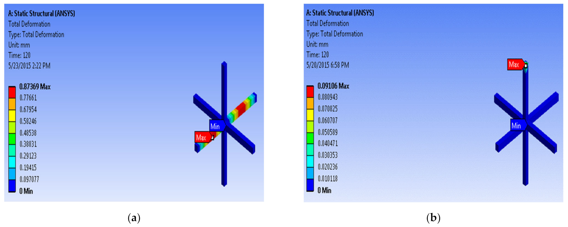
| Overall deformation (mm) | 0.87369 | 0.09106 | 89.5 |
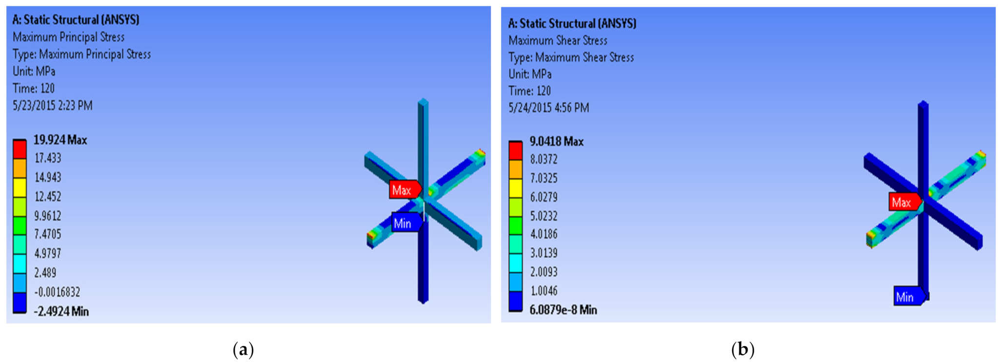
| Maximum Shear stress (MPa) | 19.92 | 9.0418 | 79.3 |
| Maximum Shear strain (mm/mm) | 0.0065 | 0.00062 | 90.4 |
| Measured Parameter | Highest Value with No MRT | Highest Value Using MRT | Variation in% |
|---|---|---|---|
| Overall deformation (mm) | 5.7922 | 0.13358 | 97.7 |
| Maximum shear stress (MPa) | 52.112 | 10.808 | 79.3 |
| Maximum shear strain (mm/mm) | 0.0009396 | 0.0003444 | 63.3 |
| Specimen ID | Overall Deformation (mm) | Maximum Shear Stress (Mpa) | Maximum Principal Elastic Strain (mm/mm) |
|---|---|---|---|
| CS4 | 0.873 | 19.92 | 0.00062 |
| SS4 | 0.091 | 9.924 | 0.00018 |
| CS5 | 5.7922 | 52.11 | 0.00093 |
| SS5 | 0.1336 | 10.81 | 0.00034 |
Publisher’s Note: MDPI stays neutral with regard to jurisdictional claims in published maps and institutional affiliations. |
© 2022 by the authors. Licensee MDPI, Basel, Switzerland. This article is an open access article distributed under the terms and conditions of the Creative Commons Attribution (CC BY) license (https://creativecommons.org/licenses/by/4.0/).
Share and Cite
Tiwary, A.K.; Singh, S.; Chohan, J.S.; Kumar, R.; Sharma, S.; Chattopadhyaya, S.; Abed, F.; Stepinac, M. Behavior of RC Beam–Column Joints Strengthened with Modified Reinforcement Techniques. Sustainability 2022, 14, 1918. https://doi.org/10.3390/su14031918
Tiwary AK, Singh S, Chohan JS, Kumar R, Sharma S, Chattopadhyaya S, Abed F, Stepinac M. Behavior of RC Beam–Column Joints Strengthened with Modified Reinforcement Techniques. Sustainability. 2022; 14(3):1918. https://doi.org/10.3390/su14031918
Chicago/Turabian StyleTiwary, Aditya Kumar, Sandeep Singh, Jasgurpreet Singh Chohan, Raman Kumar, Shubham Sharma, Somnath Chattopadhyaya, Farid Abed, and Mislav Stepinac. 2022. "Behavior of RC Beam–Column Joints Strengthened with Modified Reinforcement Techniques" Sustainability 14, no. 3: 1918. https://doi.org/10.3390/su14031918
APA StyleTiwary, A. K., Singh, S., Chohan, J. S., Kumar, R., Sharma, S., Chattopadhyaya, S., Abed, F., & Stepinac, M. (2022). Behavior of RC Beam–Column Joints Strengthened with Modified Reinforcement Techniques. Sustainability, 14(3), 1918. https://doi.org/10.3390/su14031918