Article

Deformation Capacity of RC Beam-Column Joints Strengthened with Ferrocement

1
Doctor of Engineering Study Program, Universitas Syiah Kuala, Darussalam, Banda Aceh 23111, Indonesia
2
Department of Civil Engineering, Universitas Syiah Kuala, Darussalam, Banda Aceh 23111, Indonesia
3
Department of Mechanical Engineering, Universitas Syiah Kuala, Darussalam, Banda Aceh 23111, Indonesia
*
Author to whom correspondence should be addressed.
Sustainability 2022, 14(8), 4398; https://doi.org/10.3390/su14084398
Submission received: 10 March 2022 / Revised: 2 April 2022 / Accepted: 4 April 2022 / Published: 7 April 2022

Abstract

:
Beam-column joints constructed in the pre-seismic building code do not provide transverse reinforcement and good reinforcement detailing within the region. These cause the occurrence of brittle shear failure, which is one of the factors affecting the number of reinforced concrete (RC) moment resistance building structures collapsing during an earthquake. Therefore, in this study a brittle beam-column joint with a non-seismic building code was designed and strengthened by a ferrocement. Four layers of wire mesh with a diameter of 1 mm and a mesh size of 25.4 mm were installed on both sides of the beam-column joint and cement mortar was cast on it. As a comparison, a ductile beam-column joint was also designed following the current building code, which considers seismic effects. The test results by applying reversed cyclic loading at the beam tip showed that strengthening using ferrocement prevents crack propagation, increasing the deformation capacity, ductility, stiffness, and energy dissipation of beam column joint which are higher than those of the beam-column joint which is designed following the current building code. However, the strengthening does not improve the load carrying capacity significantly.

1. Introduction

Reinforced concrete (RC) buildings constructed in the 1970s and 1980s or earlier lacked transverse reinforcement installations in the beam-column joint region. Furthermore, they did not adhere to the requirements of a detailed reinforcement to withstand seismic loads because the building code at that time did not accommodate these effects on the beam-column joint structures. In Indonesia, the building code used to design certain structures during that period was NI-2 [1]. The absence of special provisions regarding reinforcement detailing and transversal reinforcement in beam-column joint region due to the ductile design philosophy has not been adopted yet, led to the failure of the beam-column joints. Globally, it is one of the causes of collapsed buildings during earthquakes [2,3,4,5,6,7,8,9,10,11,12,13,14]. During that era, many buildings were also designed without the strong column–weak beam design philosophy which results in the appearance of column hinges in their collapse pattern. However, the column hinges were also found although the structures are designed based on the strong column–weak beam criterion [15].
Generally, the beam-column joint experiences a brittle shear failure. Therefore, efforts are needed to strengthen the structures that were built in the 70s and 80s for their sustainability [16,17,18,19]. Several structural strengthening methods have been proposed to withstand seismic loads. These include the use of Fiber Reinforced Polymer (FRP) [20,21,22,23,24,25,26,27,28,29,30,31,32,33,34,35,36,37,38,39,40], steel jacketing [20,41,42,43,44], pre-fabricated composite blocks [45], diagonal steel bars [46], steel haunch strengthening and confining joint reinforcement [44,47], injection of cracks with epoxy and concrete jacket [20,48,49], textile-reinforced engineered cementitious composites [50,51], installing reinforced concrete wing walls [52], and modified reinforcement technique [53]. However, those strengthening systems are expensive and need to be professionally installed.
Ferrocement is a type of thin reinforced concrete usually made of hydraulic cement mortar reinforced with a metallic mesh or similar materials [54] and has been used as a material for the strengthening of reinforced concrete structures. It possesses greater tensile strength and resistance to cracking than conventional reinforced concrete. Despite having similar durability, ferrocement is extremely elastic. In this study, ferrocement was used to strengthen the beam-column joint, because this method is cheap compared to the above-described methods, and its materials are always available, simple, and easy to install. Several studies have been carried out on its use as a beam strengthening material, and it was discovered to increase flexural capacity, stiffness, ductility, and energy dissipation [55,56,57,58,59,60,61]. Similarly, as a column strengthening material, it also significantly increases ductility and energy dissipation as well as load-bearing capacity and stiffness [62,63,64,65]. However, very limited studies have been carried out on beam-column joint strengthening using ferrocement [66,67,68].
This study was carried out with the aim to understand the deformation capacity of a beam-column joint designed with a non-seismic building code strengthened with ferrocement under reversed cyclic loading. The reversed cyclic loading was chosen to simulate the earthquake action in building structures since the strengthening method proposed in this study will be applied in building structures in a seismic prone area. The strengthened beam-column joint performance is then compared to the unreinforced one and used to ascertain the increase in its deformation capacity. Furthermore, it is also compared with the performance of beam-column joint designed with the current Indonesian building code [69], which considers the seismic loads effect to discern the strengthening efficiency to withstand such impacts. Therefore, it is expected that this study recommends an economical and practical structural strengthening method that is applicable when strengthening existing buildings. It is important to note that the behaviors of strengthened beam-column joint presented in this paper are only based on the experimental results. The numerical analysis with reliable models of such structure is considered for further study.

2. Experimental Program

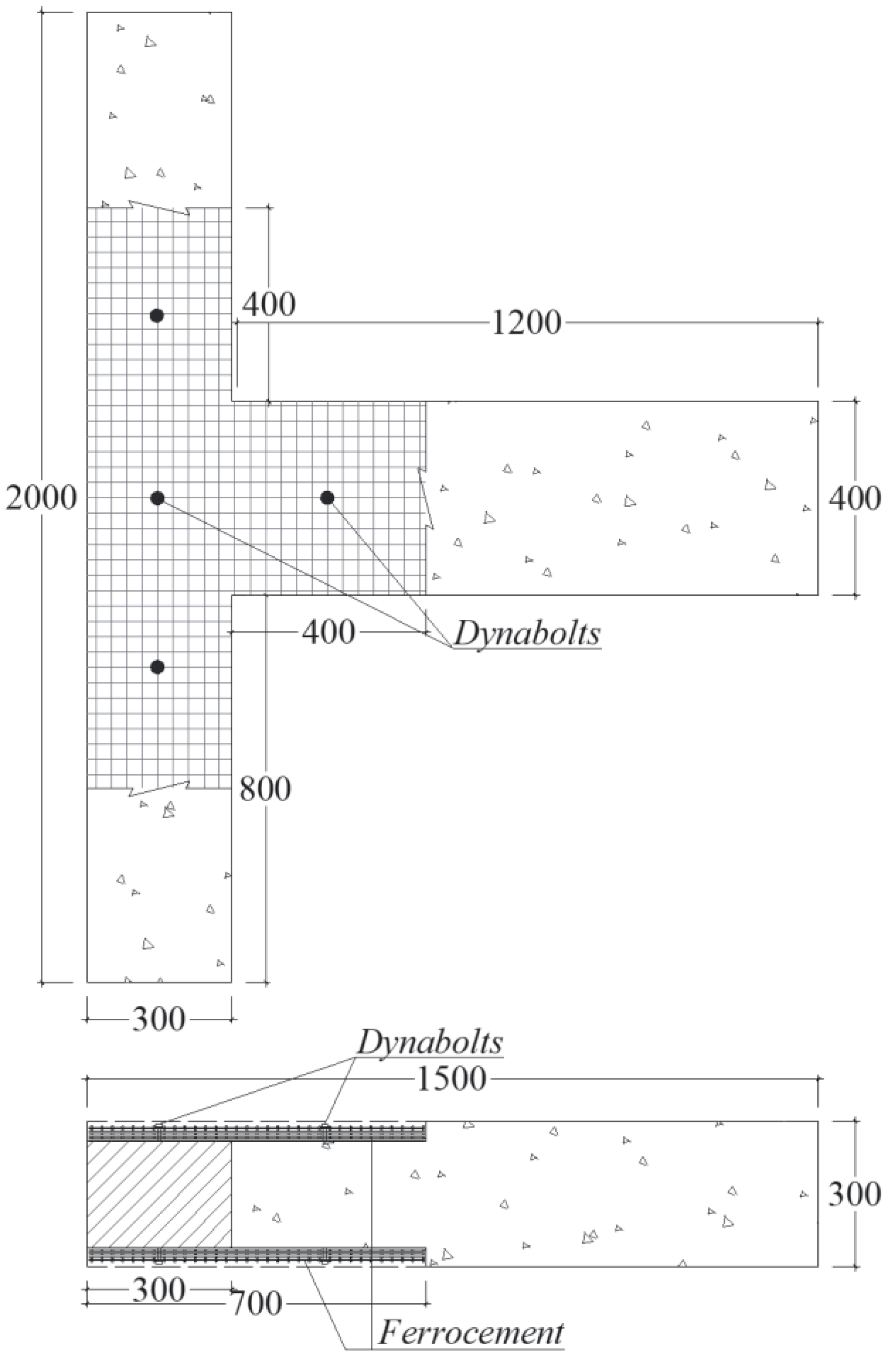
2.1. Detail of Specimens

Three beam-column joint specimens were prepared as shown in Table 1. The beams and columns are designed to have similar cross-sectional width and longitudinal reinforcements. The beam cross-section is 300 mm × 400 mm with 8D14 mm longitudinal reinforcements. Furthermore, the transverse reinforcements is in the form of D10 mm stirrups, which are installed every 100 mm distance from the column face to as far as 200 mm in its front. In the other part of the beam, D10 mm stirrups are installed within a distance of 50 mm. The column cross-section is 300 mm × 300 mm with longitudinal reinforcements of 8D14 mm. Conversely, the transverse reinforcements in the form of D10 mm stirrups are installed every 100 mm distance from the beam face to as far as 200 mm in its front. In the other part of the column, D10 mm stirrups are installed within a distance of 50 mm. The installation of a tighter stirrup in those areas is to ensure that cracks do not occur in this area when a load is applied. This is due to the fact the beam-column joint is the only part observed in this study. The weak column–strong beam was selected to represent buildings constructed in the 70s and 80s. The mix proportion and the concrete compressive strength as well as reinforcing bar yield strength and Young’s modulus used for the beam-column joints are shown in Table 2 and Table 3. The concrete compressive strength presented in Table 2 is the average compressive strength tested on 20 cylinder specimens with diameter of 150 mm and height of 300 mm at the age of 28 days, while the yield strength and elastic modulus of steel bars presented in Table 3 were obtained from the test results on one specimen for each bar diameter.
BCJ1 is a beam-column joint specimen designed according to NI-2 [1] without using transverse reinforcement in the joint region. The beam longitudinal reinforcing bars are not continuously bent towards the upper and lower columns. Figure 1 shows details of specimen BCJ1. Specimen BCJ2 has a similar size and longitudinal reinforcement as BCJI. The difference is that specimen BCJ2 added stirrups in the joint region using bars with a diameter of 10 mm placed at a spacing of 100 mm according to the current Indonesian building code [69]. The beam longitudinal reinforcing bars are also bent towards the upper and lower column with a length of 500 mm therefore their functions as anchors. Comprehensive details of specimen BCJ2 are shown in Figure 2. The specimen BCJ3 was designed in a similar manner as BCJ1. However, it was strengthened using ferrocement on both sides of the beam-column joint, as shown in Figure 3. Subsequently, the strengthening was provided in the following way. The first step involves disassembling the concrete cover of the specimen in the joint area, up to 400 mm in front of the beam and column, with a thickness until the reinforcing bars of the specimen is visible with the thickness of 40 mm. Furthermore, a T-shaped wire mesh with 1 mm diameter and 25.4 mm mesh size, similar to the beam-column joint area was cut. Four layers of wire mesh were installed and mounted on both sides of the specimen with the orientation angle of 0° to beam and column longitudinal axis as shown in Figure 4. Afterward, the wire mesh was anchored to the specimen using 4 dynabolts. Finally, a cement mortar was re-cast (Figure 5). Cement and sand with a volume ratio of 1:4 and water to cement ratio of 0.5 was used for the mortar mixture. A polycarboxylate-based superplasticizer having a specific gravity of 1.06 with a content of 1% of cement weight was also added to the mixture thereby enabling it flows easily when filling the cavities of the wire mesh during casting. Furthermore, the strengthening of the beam-column joint with ferrocement was carried out on both sides of the specimen by strengthening it on one side first, and after the mortar has hardened, the same procedure was performed on the other side.

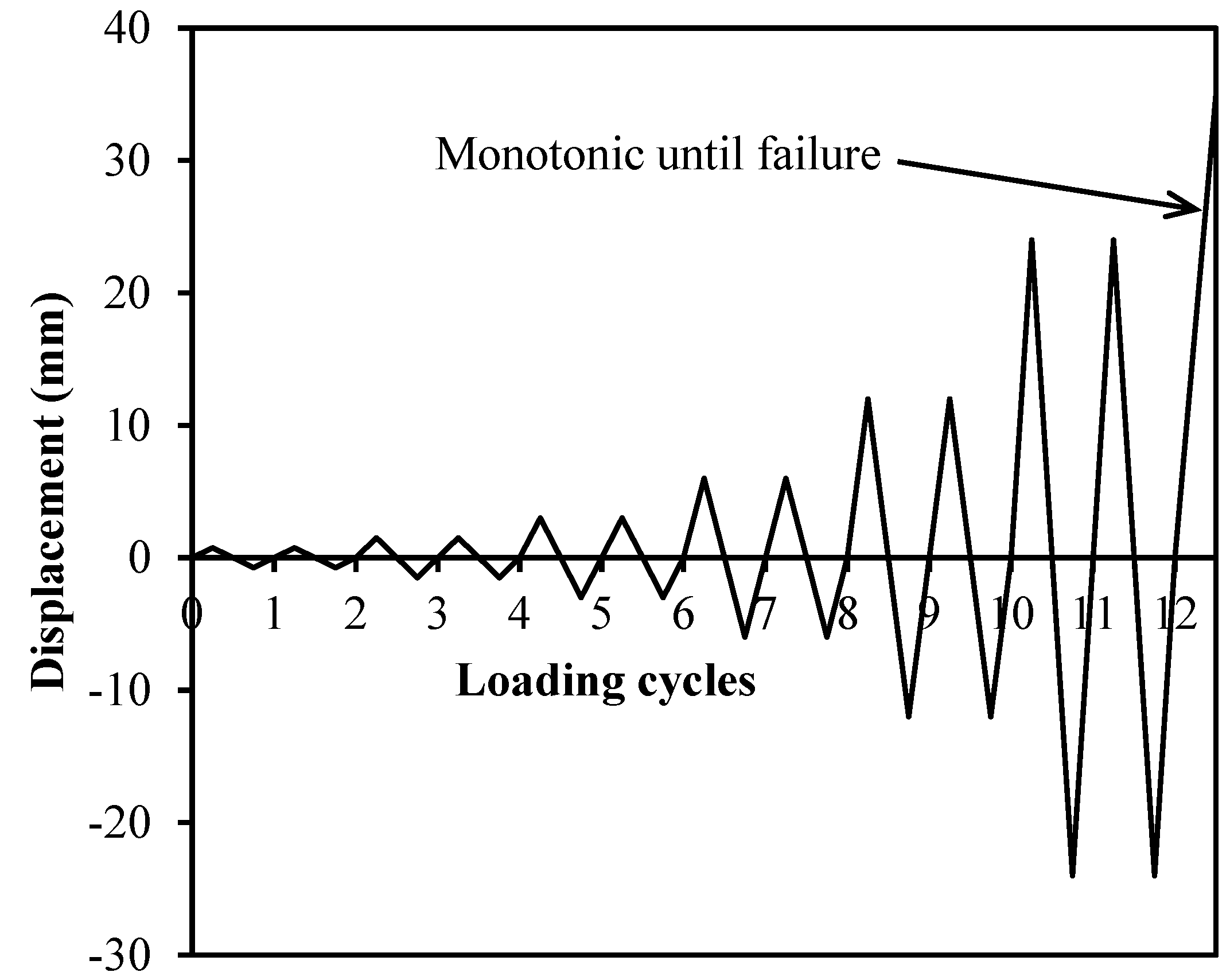
2.2. Loading Procedure

The specimen was first set on the loading frame, as shown in Figure 6. The column was placed horizontally above the loading frame by anchoring it at a distance of 200 mm from both ends using bolts. Furthermore, at both ends of the column, L shape steel is installed, welded to its longitudinal reinforcement, and anchored to the loading frame using bolts. The load is applied through an actuator driven by a hydraulic jack placed on the beam tip. A steel plate is installed on the beam surface to fasten the actuator and specimen, thereby providing a reversed cyclic loading under deformation control. Unloading and reloading were performed at the displacement of 0.75 mm, 1.5 mm, 3 mm, 6 mm, 12 mm, and 24 mm while two loading cycles were applied for each displacement as shown in Figure 7. After 12 cycles, the loading was continued with monotonic until the specimen failed.
Beam displacement was measured by installing 2 transducers on both sides at a distance of 600 mm from the column face, as shown in Figure 6. In the joint area, two π gages were mounted to measure the width of the crack that occurs. Furthermore, strain gages were installed at the longitudinal reinforcement as well as on the stirrups of the beam and column to measure the strains. Moreover, the applied load was measured with a load cell. All information acquired during loading was recorded with a data logger and entered into a computer. In addition, the crack pattern during the loading process was also observed and drawn until the failure of the specimen.

3. Results and Discussion

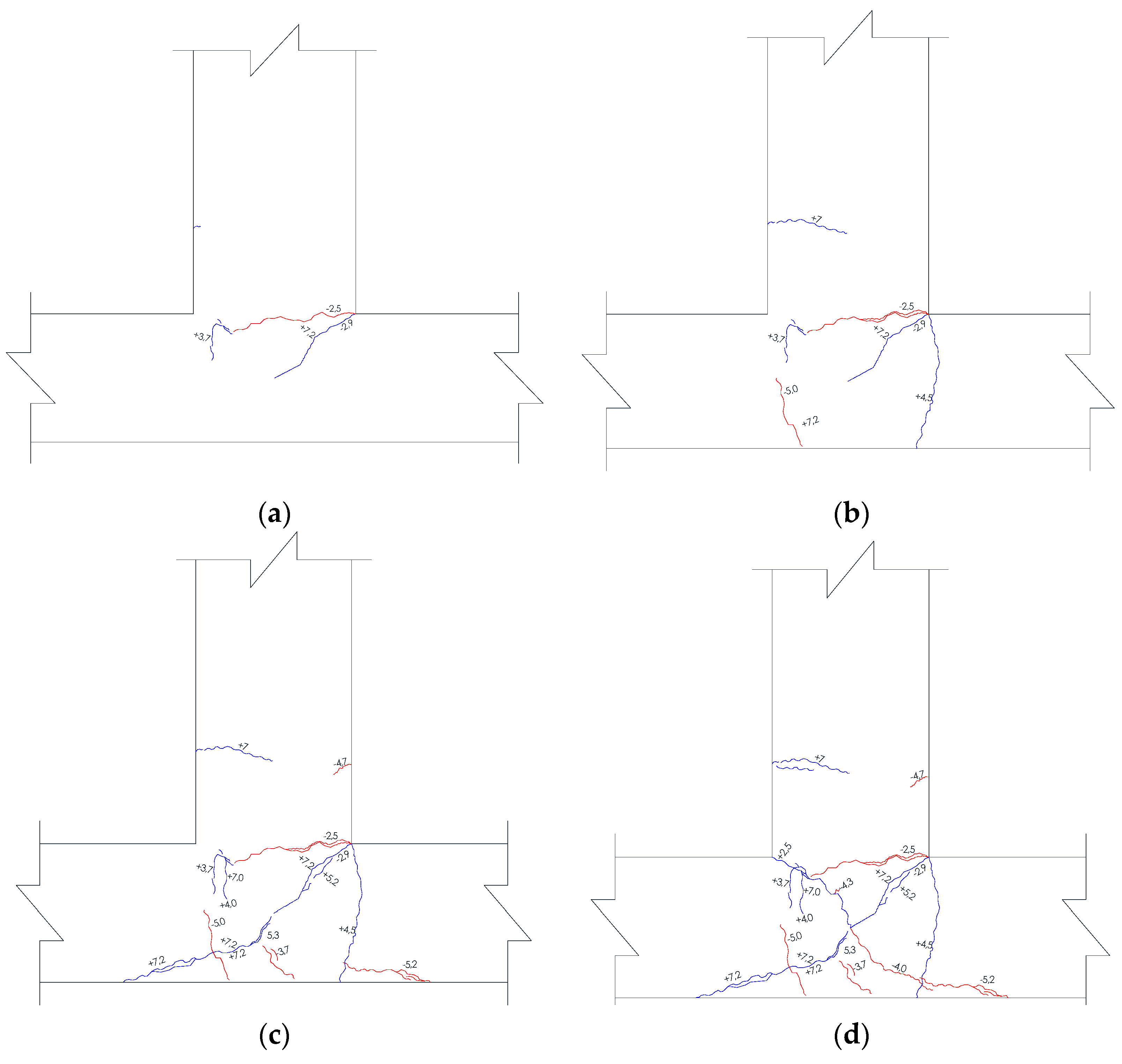
3.1. Crack Propagation and Failure Mode

Figure 8 clearly shows an image of the cracks that occurs at the BCJ1 specimen when the displacement was relatively 3 mm, 6 mm, 12 mm, and 24 mm. The crack did not occur until the displacement was approximately 1.5 mm. The first crack occurred at the beam-column joint corner in the longitudinal direction of the column towards the center of the beam in the direction of the push load. Furthermore, when the displacement was relatively 2.3 mm, the length of the first crack was increased to 300 mm. Another crack appeared at the same corner, however it was directed towards the center of the beam-column joint (inclined crack). When the displacement was approximately 3 mm, the crack that appeared first has turned towards the center of the column with a crack length of 100 mm and the inclined crack has reached the center of the beam-column joint as shown in Figure 8a. Figure 8b illustrates that when the displacement has reached 6 mm, 3 more cracks appeared, and with one starting at the corner of the beam-column joint in the longitudinal direction of the beam, it reached the other side of the column. Furthermore, another one started from the opposite side of the column in a slightly inclined direction, and the final crack appeared in the beam on the opposite side with the load applied and propagated to its center. Meanwhile, the first and second appeared cracks only increased in width. Consequently, when the displacement is relatively 12 mm, the second crack, which was an inclined crack, was propagated to the other side of the column until relatively 150 mm in front of the beam, as shown in Figure 8c. This inclined crack, as well as the horizontal one at the column face, increased in width with increasing in displacement. In addition, when the displacement was approximately 24 mm, another inclined crack appeared at another beam-column joint corner and propagated to the reverse side of the column until it was relatively 150 mm measured from the face of the beam. This crack formed an X shape together with the previously occurred inclined crack as shown in Figure 8d. Furthermore, lack of stirrups in the joint region led to a rapid increase in the width of the X crack and horizontal cracks that first appeared, thereby causing a decrease in load when the displacement reached 25.27 mm and structural failure in the subsequent cycle at 32.58 mm. The failure mode of the specimen BCJ1 is shown in Figure 9. This is a typical shear failure in the beam-column joints.
Crack propagation of specimen BCJ2 at a displacement of 3 mm, 6 mm, 12 mm, and 24 mm is shown in Figure 10. A crack occurred when a displacement exceeded 1.5 mm at the beam-column joint corner on the opposite side of the applied loading side. The crack propagated parallel to the longitudinal direction of the column. However, when the displacement was approximately 3 mm, the crack length was relatively 190 mm, as shown in Figure 10a. Another crack with a length of 30 mm simultaneously appeared on the side of the beam opposite the load. The application of a compressive load in the same cycle led to the formation of new cracks at an opposite corner which was also horizontal towards the previous one, thereby causing the two cracks to meet. At the time of applying the tensile load for the next cycle, a new crack with a length of 220 mm occurred, starting from the first one, which was located 50 mm from the face of the beam towards column’s longitudinal axis. Meanwhile, when the compressive load was applied in the same cycle, a similar incident where another crack occurred in the longitudinal axis direction of the beam leading to the inner joint, which started at the previous one with a length of 190 mm, as shown in Figure 10b. Besides, when the displacement was greater than 6 mm, inclined cracks started to occur at the joint. Furthermore, there were also cracks on the other side of the column and jointed with previous cracks in the column axis at the joint region when the displacement is relatively 12 mm, as shown in Figure 10c. In addition, when the crack in the beam propagated, its length was relatively 180 mm apart from the appearance of the other two cracks with similar lengths. Subsequently, when the displacement was approximately 24 mm, the cracks at the joint formed the X shape, as shown in Figure 10d. However, those X shape cracks did not increase in width when the displacement was greater than 24 mm, due to the stirrups provided in the joint region. This was different from specimen BCJ1, where the crack got wider and caused structural failure. In the BCJ2 case, the structure was still capable of deforming up to 52.39 mm and had only failed recently. Structural failure was also not caused by X-shaped cracks that occurred in the joints. However, it was caused by the widening of the cracks at the beam-column joint corner. The failure mode of specimen BCJ2 is shown in Figure 11.
Crack propagation of the specimen BCJ3 at displacement of relatively 3 mm, 6 mm, 12 mm, and 24 mm are shown in Figure 12. The first crack started immediately after the displacement exceeded 1.5 mm. Cracks also started from the beam-column joint corner on the loading side. In contrast to the BCJ1 and BCJ2 specimens, which the first crack was initially directed horizontally, in the BCJ3 specimen, the first crack had an inclined shape directed towards the center of the beam-column joint. Changes in the load direction led to the formation of a second crack on the other beam-column joint corner, which also had an inclined shape towards the beam-column joint center. In the next cycle a displacement of 3 mm was reached, and the 2 inclined cracks met at the middle of the column, in a vertical direction, away from the center of the beam-column joints. There was a cracked branch at a depth of approximately 1/3 of the column height in a horizontal direction towards its center as shown in Figure 12a. This crack failed to propagate and increase its width until the displacement was relatively 6 mm due to the presence of wire mesh. This was installed as a strengthening to prevent the propagation and widening of the crack as shown in Figure 12b. However, when the displacement was approximately 6 mm, another fine crack with a length of 5 mm appeared on the side of the column. As the displacement increased, the newly emerged inclined crack propagated towards the center of the beam-column joints. The initial crack also propagated towards the other side of the column. Furthermore, 2 other inclined cracks were formed, starting with the horizontal one that appeared first. Additionally, vertical and horizontal cracks appeared on the side of the column and beam respectively. There were also 2 vertical cracks in the beam ferrocement section. The shape of the crack when the displacement was relatively 12 mm is shown in Figure 12c. The crack pattern remained the same as shown in Figure 12d till the displacement was relatively 24 mm. There was an increase in the number of cracks on the beam and an additional vertical one on the side of the column. In the beam-column joint area, there was no increase in the length and width of the cracks. It was due to the presence of wire mesh installed on the beam-column joint as a strengthening way to prevent crack growth. This condition occurred in the next load cycle until the connection between the ferrocement and the old concrete surface was damaged at a displacement of 51.37 mm. This is almost similar to the maximum displacement of the BCJ2 specimen. The failure mode of the beam-column joints strengthened with ferrocement was delamination of the ferrocement from the old concrete as shown in Figure 13. Supposing the bond between the old concrete and ferrocement is made stronger, it is believed that the displacement achieved by this beam-column joint may increase, because at the time of failure the crack width in the joint area was less than 1 mm, thereby improves its deformation capacity and ductility.

3.2. Load and Displacement Relationship

The relationship between the load and displacement measured with transducers mounted on the beam for specimen BCJ1 is shown in Figure 14. The maximum load of this specimen is 73.95 kN at a displacement of 25.74 mm. When displacement was 24 mm, there was an extremely wide crack on the column face with a length has reached along the beam height. This also includes an X-shaped crack in the beam-column joint area, as shown in Figure 8d. Therefore, in the next cycle, the load only reached approximately 51.6 kN, and the specimen failed at the displacement of 32.58 mm. The absence of the anchorage of beam longitudinal reinforcement to column as well as no transverse reinforcement in beam-column joint region of this specimen led to the easy of crack propagation in this specimen, thereby leading to a small deformation capacity and ductility index. The first yield of beam’s longitudinal reinforcement of specimen BCJ1 occurred at a displacement of 12.07 mm.
The hysteretic load-deflection curve for specimen BCJ2 is shown in Figure 15. The displacement at the first yield of beam’s longitudinal reinforcement of specimen BCJ2 was 13.55 mm, which is similar to that of BCJ1. This is because both specimens have similar cross-sectional size and reinforcement. Due to the fact that specimen BCJ2 has a stirrup in the beam-column joint region, the maximum load is greater than that of the specimen BCJ1, which is 83.48 kN at a displacement of 23.15 mm. It is important to note that the presence of stirrups in the joint region and the anchorage of beam’s longitudinal reinforcement to relatively 560 mm into the column, causing delays in the widening and propagation of cracks, therefore the specimen was able to withstand any suddenly load drop as in the case of BCJ1. As a result, this specimen was able to sustain the maximum load in the next cycle. Furthermore, the specimen failure occurred at a displacement of 52.39 mm with a maximum load at failure of 77.89 kN, which was decreased by 6.7%. Therefore, the presence of transverse reinforcement in the beam-column joint region and the anchorage of beam’s longitudinal reinforcement in the column cause the deformation capacity to increase.
Figure 16 shows the hysteretic load-deflection curve for specimen BCJ3, which is a strengthening of the BCJ1 model using ferrocement. Similar to the cases of specimens BCJ1 and BCJ2, BCJ 3 experienced its first yield of longitudinal reinforcing bars at a deformation of 12.00 mm. Installation of wire mesh in the beam-column joint area had an insignificant effect on the maximum load, although it increased the deformation capacity of specimen BCJ3. The maximum load was similar to BCJ1, namely 75.64 kN at a displacement of 16 mm. In addition, this load remained constant until the displacement was 24 mm. There was no increase or decrease in load after a displacement of 16 mm because the specimen had significant number of cracks without any crack propagation and widening. The propagation and widening of cracks was prevented by wire mesh which was installed as a structural strengthening. As a result of the ferrocement strengthening, in the following cycle, the load did not decrease immediately as was the case of BCJ1, rather BCJ3 was able to undergo deformation even without increasing the load till a failure occurred at displacement of 52.04 mm with a load reduction of only 5%, which was equivalent to 71.86 kN. However, in the opposite direction, the maximum load of BCJ3 was 81.68 kN, which exceeded that of BCJ2 relatively 74.56 kN in the same loading direction. Therefore, the strengthening of beam-column joint designed with non-seismic building code using ferrocement improves the deformation capacity and ductility. The deformation capacity and ductility of strengthened beam-column joint even was higher than those of beam-column joint designed with current code. However, in this case, as previously reported, a failure occurred due to the delamination of the ferrocement from the old reinforced concrete beam-column joint. Furthermore, it is necessary to establish a good bond between the old concrete and the ferrocement, either by increasing the dynabolt anchor numbers or by providing a bonding adhesive between these old concrete and new mortar. Cases with a higher number of anchors and bonding adhesive between the old concrete and new mortar were not reviewed in this study and need to be further investigated.
The maximum loads, loads at first crack, loads at first yield of beam’s longitudinal reinforcing bars, and loads at failure together with their corresponding displacements of all specimens tested in this study are summarized in Table 4. Table 4 shows that the strengthening of beam-column joint with ferrocement did not improve the load carrying capacity, but enhanced the ability to deform after peak load. Therefore, the deformation capacity of strengthened beam-column joint was increased by 60%, which was almost similar to that was designed with current building code. To improve the load carrying capacity as well as the deformation capacity, it is recommended to use high strength heat-treated steel with fine grains for wire mesh in the future study since such steel has better performance in carrying static and dynamic loads [70,71]. This type of steel may be welded to reinforcing bars using welding heat input [72], so that the delamination of ferrocement that occurred in this study may be prevented.
The enveloped load-displacement curves of the 3 specimens tested in this study were compared as shown in Figure 17. It also shows that strengthening the beam-column joints designed with a non-seismic building code using ferrocement increases the deformation capacity. Therefore it is similar to a beam-column joint designed with a new building code that takes into account the effects of seismic.

3.3. Structural Ductility

Structural ductility is defined as the ability of a structure to undergo large inelastic deformation without experiencing significant loss of strength. In this study displacement ductility index was used for assessing the structural ductility. The displacement ductility index (μ) is defined as the ratio of ultimate displacement (Δu) to yield displacement (Δy) as follows [73]:
μ = Δ u Δ y
For specimen BCJ1, ultimate displacement is defined as displacement corresponding to 15% drop of maximum load [37,74,75,76,77]. Since the maximum load for specimens BCJ2 and BCJ3 at failure dropped only by 6.75 and 5%, respectively, then the ultimate displacement for those specimens is given as failure displacement.
The yield displacement was assessed by three different methods. For the first method, the yield displacement is defined as the displacement at the first yield of reinforcing bars as presented in Table 4. The second method is based on balance of energy. The detail description on how to calculate the yield displacement based on the balance of energy can be found in the references [68,74,75]. The third method is based on the general yielding. The detail description on how to calculate the yield displacement based on the general yielding can be found in the references [68,74]. Since the yield displacement obtained by those three different methods was almost similar, then the average value was used in calculating the displacement ductility index.
Table 5 presents the yield displacement, ultimate displacement, and displacement ductility index of all specimens tested in this study. The table shows that the structural ductility of the ferrocement-strengthened beam-column joint was improved by 91% which was higher than the ductility of beam-column joint designed with the new seismic building code. This significantly ductility improvement is due to the inhibition of the crack propagation by the resistance of the installed wire mesh. As a result, the failure of the beam-column joint, which was originally brittle, becomes more ductile. These results indicate that the structures constructed before the implementation of the seismic building code may be strengthened by using ferrocement. Therefore it is presumed to have a similar deformation capacity and ductility as building structures designed with the new seismic building code. This aids in preventing sudden collapse due to failure of the beam-column joint during an earthquake.

3.4. Stiffness Degradation

Stiffness is one of the parameter that can show the seismic performance of reinforced concrete members which is the ability to resist deformation [75,76]. In this study, the stiffness was calculated as secant modulus of envelope load-displacement curves in positive direction shown in Figure 17. Figure 18 shows the comparison of the stiffness of all beam-column joint specimens tested in this study. It further shows that the presence of wire-mesh in the beam-column joint strengthened with ferrocement tends to increase its initial stiffness due to the higher elastic modulus of wire-mesh compared to the elastic modulus of concrete. Since there was no crack and the linear load-displacement relationship at the initial stage of loading, the stiffness was constant until the displacement of around 1.5 mm. The presence of cracks that occurred due to loading leads to stiffness degradation along with an increase in beam displacement, as shown in the figure. The stiffness degradation of all tested specimens is similar and closely related to the existent crack propagation.

3.5. Energy Dissipation

The total energy given to a structure under loading is called the input energy. Some of the input energy given to a structure is absorbed (dissipated) by the structure. Energy dissipation is described as the ability of a structure to absorb energy through the yielding process in the plastic hinge region. It is used in designing an earthquake-resistant building structure that is ductile in the plastic hinge area. This, therefore, leads to plastic deformation that occurs before failure. The greater the energy dissipation of a structure, the greater it is able to withstand earthquake loads.
Energy dissipation at each cycle can be calculated from the enclosed area within load-displacement loop at this cycle. The cumulative energy dissipation is calculated by summating energy dissipated in previous cycles [68]. Figure 19 shows the cumulative energy dissipation of all beam-column joint specimens tested in this study as a function of displacement. Furthermore, when there was slight deformation, the energy dissipation of all the specimens was similar. As the displacement increased, the beam-column joint specimen strengthened with ferrocement provided greater cumulative energy dissipation than the unreinforced. The energy dissipation of ferrocement-reinforced specimens was almost similar to the specimens designed with the new seismic building code. Even at the displacement greater than 20 mm, the strengthened beam-column joint had a greater cumulative energy dissipation, which shows the effectiveness of beam-column joint strengthening using ferrocement in resisting earthquake loads.

3.6. Comparison with Previous Studies

Table 6 presents the comparison of improvement of maximum displacement, ductility, initial stiffness, and energy dissipation obtained from this study and the previous studies [66,68] with the difference in strengthening scheme. This table shows that the different strengthening scheme affects the improvement of deformation capacity. The number layer of wire mesh and its orientation angle affect the improvement of maximum displacement and ductility significantly. Meanwhile, the addition of diagonal reinforcement improves energy dissipation significantly.

4. Conclusions

In this research, the deformation capacity of the reinforced concrete beam-column joint designed with a non-seismic building code was investigated. In addition, structural strengthening was analyzed and compared with the deformation capacity of a similar structure designed with the new seismic building code. Strengthening was carried out using ferrocement provided on both sides of the beam-column joint using 4 layers of wire mesh with a diameter of 1 mm and mesh of 25.4 mm. The reversed cyclic loading test results show that the beam-column joint strengthened with ferrocement improved the deformation capacity and ductility. The beam-column joint, which initially experienced brittle shear failure after being strengthened, increased its ductility index from 2.23 to 4.26. This was greater than the ductility index of the beam-column joint designed with the new seismic building code, which was 3.84. The beam-column joint, which initially failed at a displacement of 32.58 mm after being strengthened with ferrocement, failed at a displacement of 52.04 mm and was almost the same as the displacement, which was designed with the new seismic building code. Moreover, the strengthening also significantly improved its stiffness and energy dissipation. Meanwhile the load carrying capacity of the strengthened beam-column joint was 75.64 kN, a slight higher than that of non-strengthened one which was 73.95 kN, but still lower than that was designed with new seismic building code which was 83.48 kN. The failure of the beam-column joint strengthened with ferrocement occurred due to the delamination of ferrocement from the old reinforced concrete beam-column joint.

Author Contributions

Conceptualization, M.Z.A. and A.; methodology, M.Z.A., A., M.A. and M.H.; investigation, M.Z.A.; validation, A., M.A. and M.H.; resources, M.Z.A.; writing—original draft preparation, M.H.; writing—review and editing, M.H.; supervision, S.R. All authors have read and agreed to the published version of the manuscript.

Funding

This research received no external funding.

Institutional Review Board Statement

Not applicable.

Informed Consent Statement

Not applicable.

Data Availability Statement

The data of this research is available upon request to the first author.

Acknowledgments

The authors are grateful to Delfian Masrura, Maulana Lirad, Muhammad Farizki, Mahlil, and M. Nasir for the assistance provided in obtaining the experimental activities needed for data collection.

Conflicts of Interest

The authors declare no conflict of interest.

References

  1. Peraturan Beton Bertulang Indonesia 1971 NI-2; Departemen Pekerjaan Umum dan Tenaga Listrik: Bandung, Indonesia, 1979.
  2. Celep, Z.; Erken, A.; Taskin, B.; Ilki, A. Failure of masonry and concrete buildings during the March 8, 2010 Kovancilar and Palu (Elazig) earthquakes in Turkey. Eng. Fail. Anal. 2011, 18, 868–889. [Google Scholar] [CrossRef]
  3. Coşgun, C.; Dindar, A.A.; Seçkin, E.; Önen, Y.H. Analysis of building damage caused by earthquakes in Western Turkey. Gradevinar 2013, 65, 743–752. [Google Scholar]
  4. Damcı, E.; Temur, R.; Bekdaş, G.; Sayin, B. Damages and causes on the structures during the October 23, 2011 Van earthquake in Turkey. Case Stud. Constr. Mater. 2015, 3, 112–131. [Google Scholar] [CrossRef] [Green Version]
  5. Fikri, R.; Dizhur, D.; Walsh, K.; Ingham, J. Seismic performance of reinforced concrete frame with masonry infill buildings in the 2010/2011 Canterbury, New Zealand earthquakes. Bull. Earthq. Eng. 2019, 17, 737–757. [Google Scholar] [CrossRef]
  6. Fikri, R.; Dizhur, D.; Ingham, J. Typological study and statistical assessment of parameters influencing earthquake vulnerability of commercial RCFMI buildings in New Zealand. Bull. Earthq. Eng. 2019, 17, 2011–2036. [Google Scholar] [CrossRef]
  7. Fikri, R.; Derakhshan, H.; Ingham, J. Numerical evaluation of a non-ductile RCFMI building subjected to the Canterbury, New Zealand earthquakes: A case study of the St Elmo Courts building. Structures 2020, 28, 991–1008. [Google Scholar] [CrossRef]
  8. Sezen, H.; Whittaker, A.S.; Elwood, K.J.; Mosalam, K.M. Performance of reinforced concrete buildings during the August 17, 1999 Kocaeli, Turkey earthquake, and seismic design and construction practise in Turkey. Eng. Struct. 2003, 25, 103–114. [Google Scholar] [CrossRef]
  9. Hasan, M.; Saidi, T.; Afifuddin, M.; Setiawan, B. The assessment and strengthening proposal of building structure after the Pidie Jaya earthquake in December 2016. J. King Saud Univ. Eng. Sci. 2021; in press. [Google Scholar] [CrossRef]
  10. Chang, H.Y.; Lin, K.C. Reconnaissance observations on the buildings damaged by the 2010 Taiwan Kaohsiung earthquake. Nat. Hazard 2013, 69, 237–249. [Google Scholar] [CrossRef]
  11. Kabeyasawa, T. Damages to RC school buildings and lesson froms from the 2011 East Japan earthquake. Bull. Earthq. Eng. 2017, 15, 535–553. [Google Scholar] [CrossRef]
  12. Muguruma, H.; Nishiyama, M.; Watanabe, F. Lessons learned from the Kobe earthquake—A Japanese perspective. PCI J. 1995, 40, 28–42. [Google Scholar] [CrossRef]
  13. Mitchell, D.; DeVall, R.H.; Kobayashi, K.; Tinawi, R.; Tso, W.K. Damage to concrete structures due to the January 17, 1995, Hyogo-ken Nanbu (Kobe) earthquake. Can. J. Civ. Eng. 1996, 23, 757–770. [Google Scholar] [CrossRef]
  14. Su, N. Structural evaluations of reinforced concrete buildings damaged by Chi-Chi earthquake in Taiwan. Prac. Period. Struct. Des. Constr. 2001, 6, 119–128. [Google Scholar] [CrossRef]
  15. Zhang, C.; Tao, M.X. Strong-column–weak-beam criterion for reinforced concrete frames subjected to biaxial seismic excitation. Eng. Struct. 2021, 241, 112481. [Google Scholar] [CrossRef]
  16. De Angelis, A.; Tariello, F.; De Masi, R.F.; Pecce, M.R. Comparison of different solutions for a seismic and energy retrofit of an auditorium. Sustainability 2021, 13, 8761. [Google Scholar] [CrossRef]
  17. Facconi, L.; Lucchini, S.S.; Minelli, F.; Grassi, B.; Pilotelli, M.; Plizzari, G.A. Innovative method for seismic and energy retrofitting of masonry buildings. Sustainability 2021, 13, 6350. [Google Scholar] [CrossRef]
  18. Parrella, V.F.; Molari, L. Building retrofitting system based on bamboo-steel hybrid exoskeleton structures: A case study. Sustainability 2021, 13, 5984. [Google Scholar] [CrossRef]
  19. Cardani, G.; Massetti, G.E.; Riva, D. Multipurpose retrofitting of a tower building in Brescia. Sustainability 2021, 13, 8877. [Google Scholar] [CrossRef]
  20. Gkournelos, P.D.; Triantafillou, T.C.; Bournas, D.A. Seismic upgrading of existing reinforced concrete buildings: A state-of-the-art review. Eng. Struct. 2021, 240, 112273. [Google Scholar] [CrossRef]
  21. Attari, N.; Amziane, S.; Chemrouk, M. Efficiency of beam-column joint strengthened by FRP laminates. Adv. Compos. Mater. 2010, 19, 171–183. [Google Scholar] [CrossRef]
  22. Ghobarah, A.; Said, A. Shear strengthening of beam-column joints. Eng. Struct. 2002, 24, 881–888. [Google Scholar] [CrossRef]
  23. Beydokhty, E.Z.; Shariatmadar, H. Behavior of damaged exterior RC beam-column joints strengthened by CFRP composites. Lat. Am. J. Solid Struct. 2016, 13, 880–896. [Google Scholar] [CrossRef] [Green Version]
  24. De Vita, A.; Napoli, A.; Realfonzo, R. Full sace reinforced concrete beam-column joints strengthened will steel reinforced polymer systems. Front. Mater. 2017, 4, 18. [Google Scholar] [CrossRef] [Green Version]
  25. Ghobarah, A.; Said, A. Seismic rehabilitation of beam-column joints using FRP laminates. J. Earthq. Eng. 2001, 5, 113–129. [Google Scholar] [CrossRef]
  26. Pohoryles, D.A.; Melo, J.; Rossetto, T.; Varum, H. Seismic retrofit schemes with FRP for deficient RC beam-column joints: State-of-the-art review. J. Compos. Constr. 2019, 23, 03119001. [Google Scholar] [CrossRef] [Green Version]
  27. Li, B.; Chua, H.Y.G. Seismic performance of strengthened reinforced concrete beam-column joints using FRP composites. J. Struct. Eng. 2009, 135, 1177–1190. [Google Scholar] [CrossRef]
  28. Mahmoud, M.H.; Afefy, H.M.; Kassem, N.M.; Fawzy, T.M. Strengthening of defected beam-column joints using CFRP. J. Adv. Res. 2014, 5, 66–77. [Google Scholar] [CrossRef] [Green Version]
  29. Zhao, Y.; Liu, Y.; Li, J. Study of seismic behavior of RC beam-column joints strengthened by sprayed FRP. Adv. Mater. Sci. Eng. 2018, 2018, 3581458. [Google Scholar] [CrossRef] [Green Version]
  30. Santarsiero, G. FE modelling of the seismic behavior of wide beam-column joints strengthened with CFRP systems. Buildings 2018, 8, 31. [Google Scholar] [CrossRef] [Green Version]
  31. Katakalos, K.; Manos, G.; Papakonstantinou, C. Seismic retrofit of R/C T-beams with steel fiber polymers under cyclic loading conditions. Buildings 2019, 9, 101. [Google Scholar] [CrossRef] [Green Version]
  32. Baji, H.; Eslami, A.; Ronagh, A.R. Development of a nonlinear FE modelling approach for FRP-strengthened RC beam-column connections. Structures 2015, 3, 272–281. [Google Scholar] [CrossRef]
  33. Roy, B.; Laskar, A.I. Cyclic performance of beam-column subassemblies with construction joint in column retrofitted with GFRP. Structures 2018, 14, 290–300. [Google Scholar] [CrossRef]
  34. Attari, N.; Youcef, Y.S.; Amziane, S. Seismic performance of reinforced concrete beam–column joint strengthening by frp sheets. Structures 2019, 20, 353–364. [Google Scholar] [CrossRef]
  35. Maheri, M.R.; Torabi, A. Retrofitting external RC beam-column joints of an ordinary MRF through plastic hinge relocation using FRP laminates. Structures 2019, 22, 65–75. [Google Scholar] [CrossRef]
  36. Tahnat, Y.B.A.; Samaaneh, M.A.; Dwaikat, M.M.S.; Halahla, A.M. Simple equations for predicting the rotational ductility of fiber-reinforcedpolymer strengthened reinforced concrete joints. Structures 2020, 24, 73–86. [Google Scholar] [CrossRef]
  37. Akhlaghi, A.; Mostofinejad, D. Experimental and analytical assessment of different anchorage systems used for CFRP flexurally retrofitted exterior RC beam-column connections. Structures 2020, 28, 881–893. [Google Scholar] [CrossRef]
  38. Tafsirojjaman, T.; Fawzia, S.; Thambiratnam, D.P. Structural behaviour of CFRP strengthened beam-column connections under monotonic and cyclic loading. Structures 2021, 33, 2689–2699. [Google Scholar] [CrossRef]
  39. Davodikia, B.; Saghafi, M.H.; Golafshar, A. Experimental investigation of grooving method in seismic retrofit of beam-column external joints without seismic details using CFRP sheets. Structures 2021, 34, 4423–4434. [Google Scholar] [CrossRef]
  40. Murad, Y.Z.; Alseid, B.H. Retrofitting interior RC beam-to-column joints subjected to quasi-static loading using NSM CFRP ropes. Structures 2021, 34, 4158–4168. [Google Scholar] [CrossRef]
  41. Alcocer, S.M.; Jirsa, J.O. Strength of reinforced concrete frame connections rehabilitated by jacketing. ACI Struct. J. 1993, 90, 249–261. [Google Scholar]
  42. Ghobarah, A.; Aziz, T.S.; Biddah, A. Rehabilitation of reinforced concrete frame connections using corrugated steel jacketing. ACI Struct. J. 1997, 94, 283–294. [Google Scholar]
  43. Ghobarah, A.; Biddah, A.; Mahgoub, M. Seismic retrofit of reinforced concrete columns using steel jackets. Eur. Earthq. Eng. 1997, 11, 21–31. [Google Scholar]
  44. Truong, G.T.; Dinh, N.H.; Kim, J.C.; Choi, K.K. Seismic performance of exterior RC beam–column joints retrofitted using various retrofit solutions. Int. J. Concr. Struct. Mater. 2017, 11, 415–433. [Google Scholar] [CrossRef] [Green Version]
  45. Misir, I.S.; Kahraman, S. Strengthening of non-seismically detailed reinforced concrete beam column joints using SIFCON blocks. Shadana 2013, 38, 69–88. [Google Scholar] [CrossRef] [Green Version]
  46. Gokdemir, H.; Tankut, T. Seismic strengthening of beam-column joints using diagonal steel bars. Teknik Dergi 2017, 28, 7977–7992. [Google Scholar]
  47. Adil, D.M.; Subramanian, N.; Sumeet, P.; Dar, A.R.; Raju, J. Performance evaluation of different strengthening masures for exterior beam-column joints under opening moments. Struct. Eng. Mech. 2020, 74, 243–254. [Google Scholar] [CrossRef]
  48. Yurdakul, Ö.; Avşar, Ö.; Kilinç1, K. Application of different rehabilitation and strengthening methods for insufficient RC beam-column joints. Adv. Mater. Res. 2013, 688, 222–229. [Google Scholar] [CrossRef]
  49. Engindeniz, M.; Kahn, L.F.; Zureick, A.H. Repair and Strengthening of Reinforced Concrete Beam-Column Joints: State of the Art. ACI Struct. J. 2005, 102, 187–197. [Google Scholar]
  50. Yan, Y.; Liang, H.; Lu, Y.; Zhao, X. Slender CFST columns strengthened with textile-reinforced engineered cementitious composites under axial compression. Eng. Struct. 2021, 241, 112483. [Google Scholar] [CrossRef]
  51. Qian, H.; Guo, J.; Yang, X.; Lin, F. Seismic rehabilitation of gravity load-designed interior RC beam-column joints using ECC-infilled steel cylinder shell. Structures 2021, 34, 1212–1228. [Google Scholar] [CrossRef]
  52. Li, Y.; Sanada, Y. Seismic strengthening of existing RC beam-column joints by wing walls. Earthq. Eng. Struct. Dyn. 2017, 46, 1987–2008. [Google Scholar] [CrossRef] [Green Version]
  53. Tiwary, A.K.; Singh, S.; Chohan, J.S.; Kumar, R.; Sharma, S.; Chattopadhyaya, S.; Abed, F.; Stepinac, M. Behavior of RC Beam–Column Joints Strengthened with Modified Reinforcement Techniques. Sustainability 2022, 14, 1918. [Google Scholar] [CrossRef]
  54. ACI 549.1R-18: Design Guide for Ferrocement; American Concrete Institute: Farmington Hills, MI, USA, 2018.
  55. Paramasivam, P.; Lim, C.T.E.; Ong, K.C.G. Strengthening of RC beams with ferrocement laminates. Cem. Concr. Compos. 1998, 20, 53–65. [Google Scholar] [CrossRef]
  56. Raghunathapandian, P.; Palani, B.; Elango, D. Flexural strengthening of RC tee beams using ferrocement. Int. J. Recent Technol. Eng. 2020, 8, 2277–3878. [Google Scholar]
  57. Shakthivel, V.; Pradeep Kumar, C. Experimental investigation of strengthening of RC beam using ferro cement laminates. Int. J. Eng. Tech. 2019, 5, 186–195. [Google Scholar]
  58. Khan, S.U.; Rafeeqi, S.F.A.; Ayub, T. Strengthening of RC beams in flexural using ferrocement. IJST Transac. Civ. Eng. 2013, 37, 353–365. [Google Scholar]
  59. Khan, S.U.; Nuruddin, M.F.; Ayub, T.; Shafiq, N. Effects of ferrocement in strengthening the serviceability properties of reinforced concrete structures. Adv. Mater. Res. 2013, 690–693, 686–690. [Google Scholar] [CrossRef]
  60. Makki, R.F. Response of reinforced concrete beams retrofitted by ferrocement. Int. J. Sci. Technol. Res. 2014, 3, 27–34. [Google Scholar]
  61. Miah, M.J.; Miah, M.S.; Alam, W.B.; Lo Monte, F.; Li, Y. Strengthening of RC beams by ferrocement made with unconventional concrete. Mag. Civ. Eng. 2019, 89, 94–105. [Google Scholar] [CrossRef]
  62. Abdullah; Takiguchi, K. An investigation into the behavior and strength of reinforced concrete columns strengthened with ferrocement jackets. Cem. Concr. Compos. 2003, 25, 233–242. [Google Scholar] [CrossRef]
  63. Mourad, S.M.; Shannag, M.J. Repair and strengthening of reinforced concrete square column using ferrocement jackets. Cem. Concr. Compos. 2012, 34, 288–294. [Google Scholar] [CrossRef]
  64. Jiang, L.M.; Tang, F.H.; Ou, M.L. Experimental research on the strengthening of RC columns by high performance ferrocement laminates. Adv. Mater. Res. 2011, 243–249, 1409–1415. [Google Scholar] [CrossRef]
  65. Kaish, A.B.M.A.; Jamil, M.; Raman, S.N.; Zain, M.F.M.; Nahar, L. Ferrocement composites for strengthening of concrete columns: A review. Constr. Build. Mater. 2018, 160, 326–340. [Google Scholar] [CrossRef]
  66. Shaaban, I.G.; Seoud, O.A. Experimental behavior of full-scale exterior beam-column space joints retrofitted by ferrocement layers under cyclic loading. Case Stud. Constr. Mater. 2018, 8, 61–78. [Google Scholar] [CrossRef]
  67. Shaaban, I.G.; Said, M. Finite element modeling of exterior beam-column joints strengthened by ferrocement under cyclic loading. Case Stud. Constr. Mater. 2018, 8, 333–346. [Google Scholar] [CrossRef]
  68. Li, B.; Lam, E.S.S.; Wu, B.; Wang, Y.Y. Experimental investigation on reinforced concrete interior beam–column joints rehabilitated by ferrocement jackets. Eng. Struct. 2013, 56, 897–909. [Google Scholar] [CrossRef]
  69. SNI 2847:2019 Persyaratan Beton Struktural Untuk Bangunan Gedung Dan Penjelasan; Badan Standardisasi Nasional: Jakarta, Indonesia, 2019.
  70. Tuz, L. Determination of the causes of low service life of the air fan impeller made of high-strength steel. Eng. Fail. Anal. 2021, 127, 105502. [Google Scholar] [CrossRef]
  71. Tuz, L. Evaluation of microstructure and selected mechanical properties of laser beam welded S690QL high-strength steel. Adv. Mater. Sci. 2018, 18, 34–42. [Google Scholar] [CrossRef] [Green Version]
  72. Nowacki, J.; Sajek, A.; Matkowski, P. The influence of welding heat input on the microstructure of joints of S1100QL steel in one-pass welding. Arch. Civ. Mech. Eng. 2016, 16, 777–783. [Google Scholar] [CrossRef]
  73. Park, R.; Paulay, T. Reinforced Concrete Structures; Wiley: Hoboken, NJ, USA, 1975. [Google Scholar]
  74. Dabiri, H.; Kheyroddin, A.; Kaviani, A. A numerical study on the seismic response of RC wide column–beam joints. Int. J. Civ. Eng. 2019, 17, 377–395. [Google Scholar] [CrossRef]
  75. Kheyroddin, A.; Mohammadkhah, A.; Dabiri, H.; Kaviani, A. Experimental investigation of using mechanical splices on the cyclic performance of RC columns. Structures 2020, 24, 717–727. [Google Scholar] [CrossRef]
  76. Kheyroddin, A.; Dabiri, H. Cyclic performance of RC beam-column joints with mechanical or forging (GPW) splices; an experimental study. Structures 2020, 28, 2562–2571. [Google Scholar] [CrossRef]
  77. Dabiri, H.; Kheyroddin, A. An experimental comparison of RC beam-column joints incorporating different splice methods in the beam. Structures 2021, 34, 1603–1613. [Google Scholar] [CrossRef]
Figure 1. Detail specimen BCJ1.
Sustainability 14 04398 g001
Figure 2. Detail specimen BCJ2.
Sustainability 14 04398 g002
Figure 3. Detail specimen BCJ3.
Sustainability 14 04398 g003
Figure 4. Wire mesh already installed on one side of the beam-column joint.
Sustainability 14 04398 g004
Figure 5. Re-casting the beam-column joint after installing the wire mesh.
Sustainability 14 04398 g005
Figure 6. Loading set up.
Sustainability 14 04398 g006
Figure 7. Displacement controlled loading history.
Sustainability 14 04398 g007
Figure 8. Crack propagation of specimen BCJ1 at displacement of: (a) 3 mm; (b) 6 mm; (c) 12 mm; and (d) 24 mm.
Sustainability 14 04398 g008
Figure 9. The failure mode of specimen BCJ1.
Sustainability 14 04398 g009
Figure 10. Crack propagation of specimen BCJ2 at displacement of: (a) 3 mm; (b) 6 mm; (c) 12 mm; (d) 24 mm.
Sustainability 14 04398 g010
Figure 11. The failure mode of specimen BCJ2.
Sustainability 14 04398 g011
Figure 12. Crack propagation of specimen BCJ3 at displacement of: (a) 3 mm; (b) 6 mm; (c) 12 mm; (d) 24 mm.
Sustainability 14 04398 g012
Figure 13. The failure mode of specimen BCJ3.
Sustainability 14 04398 g013
Figure 14. The hysteretic load-displacement curve for specimen BCJ1.
Sustainability 14 04398 g014
Figure 15. The hysteretic load-displacement curve for specimen BCJ2.
Sustainability 14 04398 g015
Figure 16. The hysteretic load-displacement curve for specimen BCJ3.
Sustainability 14 04398 g016
Figure 17. Envelope load-displacement curves.
Sustainability 14 04398 g017
Figure 18. Degradation of stiffness.
Sustainability 14 04398 g018
Figure 19. Cumulative energy dissipation.
Sustainability 14 04398 g019
Table 1. Detail of specimens.
SpecimenDescription
BCJ1Beam column joint designed based on NI-2 [1]
BCJ2Beam column joint designed based on SNI 2847:2020 [69]
BCJ3Beam column joint designed based on NI-2 [1] and strengthened with ferrocement
Table 2. Mix proportion of concrete.
MaterialsQuantity
Cement (kg)317
Water (kg)205
Fine sand (kg)365
Coarse sand (kg)729
Split stone dmax 20 mm (kg)729
w/c0.65
Slump (mm)12
Compressive strength (MPa)24.8
Table 3. Yield strength and Young’s modulus of reinforcing bars.
Bar Diameter (mm)Yield Strength, fy (MPa)Young’s Modulus (GPa)
14310200
10375200
Table 4. Maximum loads (Pmax), loads at first crack (Pcr), loads at first yield of reinforcing bars (Py) and loads at failure (Pfail) and their corresponding displacements (Δ).
SpecimenLoad (kN) and Displacement (mm)Ratio of Δfail to Δfail,BCJ1
At First CrackAt First YieldMaximumAt Failure
PcrΔcrPyΔy1PmaxΔmPfailΔfail
BCJ122.681.8056.8512.0773.9524.0151.632.581.00
BCJ229.531.5768.3813.5583.4823.1577.8952.391.61
BCJ334.141.5565.1412.0075.6424.0071.8652.041.60
Table 5. Displacement ductility index.
SpecimenΔu (mm)First Yield, Δy1 (mm)Balance of Energy, Δy2 (mm)General Yielding, Δy3 (mm)Δy,avg (mm)μRatio of μ to μBCJ1
BCJ127.6012.0712.4212.6512.382.231.00
BCJ252.3913.5513.6513.7813.663.841.72
BCJ352.0412.0012.2612.4312.234.261.91
Table 6. Comparison of improvement of maximum displacement, ductility, initial stiffness, and energy dissipation obtained from this study and the previous studies [66,68].
Strengthening SchemeImprovement in (%)
Orientation AngleNumber Layer of Wire MeshMaximum DisplacementDuctilityInitial StiffnessEnergy Dissipation
0° (Present study)460912971
45° [66]318NA *1216
60° [66]320NA *6821
0° with addition of diagonal reinforcement [68]2221719154
NA * = not available.
Publisher’s Note: MDPI stays neutral with regard to jurisdictional claims in published maps and institutional affiliations.

