Article

Indoor Thermal Environment and Energy Characteristics with Varying Cooling System Capacity and Restart Time

1
Department of Building and Plant Engineering, Hanbat National University, Daejeon 34158, Korea
2
Department of Architectural Engineering, Hanbat National University, Daejeon 34158, Korea
*
Author to whom correspondence should be addressed.
Sustainability 2022, 14(15), 9392; https://doi.org/10.3390/su14159392
Submission received: 30 June 2022 / Revised: 25 July 2022 / Accepted: 27 July 2022 / Published: 31 July 2022
(This article belongs to the Special Issue Research and Practice of Sustainable Construction Project Management)

Abstract

:
Office cooling systems are controlled with on/off control according to typical occupancy patterns. During unoccupancy, the cooling systems remain switched off to reduce unnecessary energy consumption. During occupancy, however, the cooling systems are in operation to decrease the indoor air temperature, which is increased during unoccupancy, to the cooling set-point temperature. The time required to decrease the indoor air temperature to the cooling set-point temperature is defined as the “recovery time”. According to the recovery time, the indoor thermal comfort at the occupancy start time may worsen, and unnecessary energy may be consumed. Moreover, a cooling system capacity affects the recovery time and the energy consumption because the amount of heat that the cooling system can remove varies according to its size. Therefore, it is necessary to analyze the indoor thermal environment and the energy consumption according to the capacity and the restart time of the cooling system. This study implemented a building system energy simulation using EnergyPlus to evaluate the indoor air temperature, recovery time, and energy consumption of the cooling system while varying the capacity and restart time. As a result, the recovery time was between 49 and 425 min. and energy consumption varied between 419.0 and 521.4 kWh for various capacities. The recovery time was between 26 and 153 min. and energy consumption was between 426.0 and 439.0 kWh for various restart times.

1. Introduction

The standard functionality of an office building often involves a typical occupancy pattern in which occupancy (i.e., daytime) and unoccupancy (i.e., nighttime, weekends, and holiday) are repeated according to standard working hours. An office cooling system should be operated intermittently according to the occupancy patterns to reduce energy consumption. Among the methods for intermittent operation, an on/off control is widely used as the operation method. The on/off control determines the on/off state of the system. If the cooling system is operated with on/off control, it is operated only during the occupancy periods to maintain indoor air temperatures below a cooling set-point temperature. During the unoccupancy period, on the other hand, the cooling system is switched off to prevent unnecessary energy consumption. In this manner, the majority of the office buildings operate the cooling system energy-efficiently. When the cooling systems are operated with the on/off control, the indoor air temperature gradually increases during the unoccupancy period. A system operator re-operates the cooling system before the occupancy start time for preliminary cooling, lowering the indoor air temperature to the cooling set-point temperature. Because of the pre-cooling, occupants are able to start working at the beginning of the occupancy period in a thermally comfortable environment. After re-starting the cooling system, a certain period of time is required (i.e., recovery time) for the indoor air temperature to drop to the cooling set-point temperature. The recovery time is affected by a cooling system restart time (CSRT). If the CSRT is set to be late, the recovery time increases because the indoor air temperature before restarting the cooling system rises. If the indoor air temperature does not reach the cooling set-point temperature by the start of the occupancy period, due to the increased recovery time, the thermal comfort of the occupants decreases, causing a decrease in work efficiency of the occupants [1]. To ensure the sufficient pre-cooling time, the CSRT is generally set to 1~2 h before the occupancy start time. However, if the CSRT is set to be early, then unnecessary energy is consumed. For this reason, the appropriate CSRT should be selected by considering the recovery time (see Figure 1a). To improve the existing on/off control, various studies on the start/stop time of a heating, ventilation, and air conditioning (HVAC) system were conducted.
Yang et al. developed an artificial neural network (ANN) model that predicts the optimal start time of the HVAC system to achieve both the thermal comfort satisfaction and the reduced energy usage [2]. They predicted the optimal start time of the HVAC system using the indoor air temperature, rate of indoor air temperature change, outdoor air temperature, and rate of outdoor air temperature change as input parameters of the ANN model. Their ANN model prediction accuracy evaluation using existing data results showed that the correlation between existing and ANN data was shown by the coefficient of determination R² = 0.988. This result suggests that their ANN model can accurately determines the optimal start time of the HVAC system.
Fadzli Haniff et al. analyzed the energy consumption and cost of HVAC system operation methods for the energy-efficient operation of a heating and ventilation system [3]. They classified the HVAC system operation methods into the following types: (1) basic technology that controls only the on/off state of the HVAC system, (2) conventional technology that controls only the set-point temperature of the HVAC system, and (3) advanced technology that simultaneously controls the operation state and the set-point temperature of the HVAC system. As a result of comparative analysis, advanced technology provided the most significant energy savings.
Moon and Jung developed an algorithm based on the ANN model that predicted the time required to reach the cooling set-point temperature to promote the thermal comfort and save energy in accommodation buildings [4]. A comparison of the existing data and the data predicted using the ANN model provided a mean bias error (MBE) of 21.9%. In addition, the result of the algorithm tests showed improvements in occupant comfort and a reduction in energy consumption.
Lee and Koo developed an algorithm for determining the optimal start/stop time of a HVAC system to reduce the energy consumption of small- and medium-sized buildings [5]. The algorithm was used to calculate the optimal start/stop time using the changes in the HVAC system energy consumption and indoor air temperature. Then, they applied the algorithm to a simulation model and conducted the simulation. Results of the simulation showed that the energy consumption was reduced by approximately 10% compared to the existing control.
Tang et al. developed a cooling system optimal control method to reduce the pre-cooling time of a high-rise commercial building, thereby decreasing the peak power demand during the pre-cooling period [6]. The optimal control method determined the optimal number and operation schedule of chillers operated during the pre-cooling period. When pre-cooling is performed with the optimal control method, the pre-cooling time is reduced by approximately 35%. In addition, the peak power demand during the pre-cooling period decreased by approximately 26%.
Jang et al. predicted an optimal heating system restart time to reduce building energy [7]. They developed an ANN model for predicting the optimal heating system restart time and trained the ANN model using data collected from BEMS. The prediction accuracy of the ANN model was shown by the coefficient of variation of the root-mean-squared error (Cv(RMSE)) = 13.13% and MBE = 0.197%, which meet the recommended standard of an American society of heating, refrigerating, and air-conditioning engineers (ASHRAE) guideline 14.
Park et al. developed an ANN model that was used to determine the optimal start/stop time of an air handling unit (AHU) and chiller to reduce the energy consumption [8]. For this purpose, they combined the AHU model that predicted the time required for the indoor air temperature to reach 26 °C with a chiller model that predicted the time required for the temperature of chilled water to reach 12.5 °C. The ANN model showed a reduction in the AHU and chiller operation times of approximately 4.5% and 16.4%, respectively, based on a comparison with an existing control method.
Shin et al. developed an optimal start/stop control method for an underfloor heating system according to the presence or absence of occupants [9]. They proposed an algorithm used to predict the occupancy or unoccupancy of an indoor space using a passive infrared (PIR) sensor and CO2 sensor. The algorithm verification with real occupancy data confirmed that the occupancy prediction accuracy of the algorithm was approximately 95%. The optimal start/stop control algorithm provided energy savings of approximately 3.1% and a reduction in unmet load hours of approximately 86.7% compared to the existing control method.
Yang developed an optimal operation control for heating systems to reduce heating energy in office buildings [10]. An ANN model that determines the optimal operating time of the heating system was developed for the optimal operation control. The prediction performance of the ANN model was shown by R = 0.995. By operating the heating system with the optimized control method, energy consumption was reduced by approximately 6.1% compared to the existing control method.
Lee and Kim studied an optimal control strategy for a variable refrigerant flow (VRF) system to reduce building energy consumption [11]. They developed a data-based model to predict the time required to reach the cooling set-point temperature using the difference between the indoor air and set-point temperatures. When the actual VRF system was operated using the data-based model, the energy consumption per outdoor unit was reduced by approximately 30.5% compared to the existing control method.
Previous studies generally focus on improving the indoor thermal comfort and reducing the energy consumption by applying the optimal control method to HVAC systems. Although restart time is an important factor in terms of developing an optimal control method of the HVAC system, there are few studies that focus on this factor. A detailed analysis of indoor thermal environment and energy characteristics, according to the restart time of the HVAC system, is essential to improve thermal comfort and reduce energy consumption. Furthermore, this study determined that the capacity of the cooling system is an important factor that affects the indoor thermal environment and energy consumption. The undersized capacity due to the old system as time passes and the repurposing of a building cause an increase in the recovery time. The oversized capacity due to the capacity calculation error causes an increase in the system installation cost (see Figure 1b). Therefore, this study analyzed the effects of the capacity-load ratio (CLR) and CSRT on both the indoor thermal environment and energy consumption. The CLR is fraction of the capacity of the system to the load, calculated as the ratio of the amount of load to the capacity of the system. This study involves the simulation of building system energy to evaluate the indoor air temperature, recovery time, and energy consumption of a cooling system, while varying CLR and CSRT.

2. Methodology

2.1. Overall Study Process

The purpose of this study is to analyze the effect of CLR and CSRT on the indoor thermal environment and energy consumption. This study was conducted in three steps: development of a building and system simulation model, determination of specific simulation cases, and analysis of simulation results. Each step is detailed in Figure 2.
The first step involved the development of a simulation model. This study defined input data for simulation modeling by reviewing the literatures and performed simulation modeling using the EnergyPlus ver.9.3., a building energy simulation tool [12]. The second step involved the determination of specific simulation cases. This study performed a pre-simulation and determined the CLR value and the CSRT of the base-case model to 1.2 and 8:00 a.m., respectively. After determining the base-case model, this study defined the seven simulation cases for the CLR, and five simulation cases for the CSRT. The third step involved the analysis of simulation results. This study analyzed the effects of the CLR and CSRT on the indoor thermal environment and energy characteristics based on the simulation results.

2.2. Simulation Modeling

2.2.1. Base-Case Model

This study performed the simulation modeling using EnergyPlus to develop the office-type base-case model. Figure 3 shows the 3D view of the building and simplified HVAC system, and Table 1 shows a summary of the input parameters used for simulation modeling. This study developed the office building that embodied the first floor of the ASHRAE Standard 90.1 Medium Office Model [13]. The volume of the building model was 4800 m3 (40 m × 40 m × 3 m), and the U-value of the building constructions met the standard of building energy saving in the Republic of Korea [14]. The area of windows in the exterior walls were set to 39.6 m2 (window wall-ratio (WWR): 33%); the occupancy period of the building was 9:00 a.m. to 6:00 p.m.; and the cooling set-point temperature was set to 26 °C [15]. The simulation model used a typical variable air volume (VAV) system, consisted of a cooling coil, two fans (supply and return), a chiller, two circulation pumps (chilled water loop and condenser loop), and a cooling tower. This study conducted simulation using the international weather files for energy calculation 2.0 (IWEC2) in Daejeon [16]. This study selected the simulation period from 8 to 10, August; 8–9 were weekend days (unoccupied days), and 10, the day with the highest outdoor air temperature of the year in the IWEC2, was Monday (occupied day). This study analyzed the indoor thermal environment and the energy consumption on 10 August.

2.2.2. Heat Balance Algorithm

As the occupancy period of an office building is determined according to the office work hours (9:00 a.m. to 6:00 p.m.), its cooling system is not operated during the weekends (unoccupancy period). During unoccupancy, heat is stored in the indoor space and construction, which leads to an excessive load on Monday morning when the cooling system is restarted after the weekends. As this study employs a simulation, this study reflected the heat storage in the simulations using a heat balance algorithm.
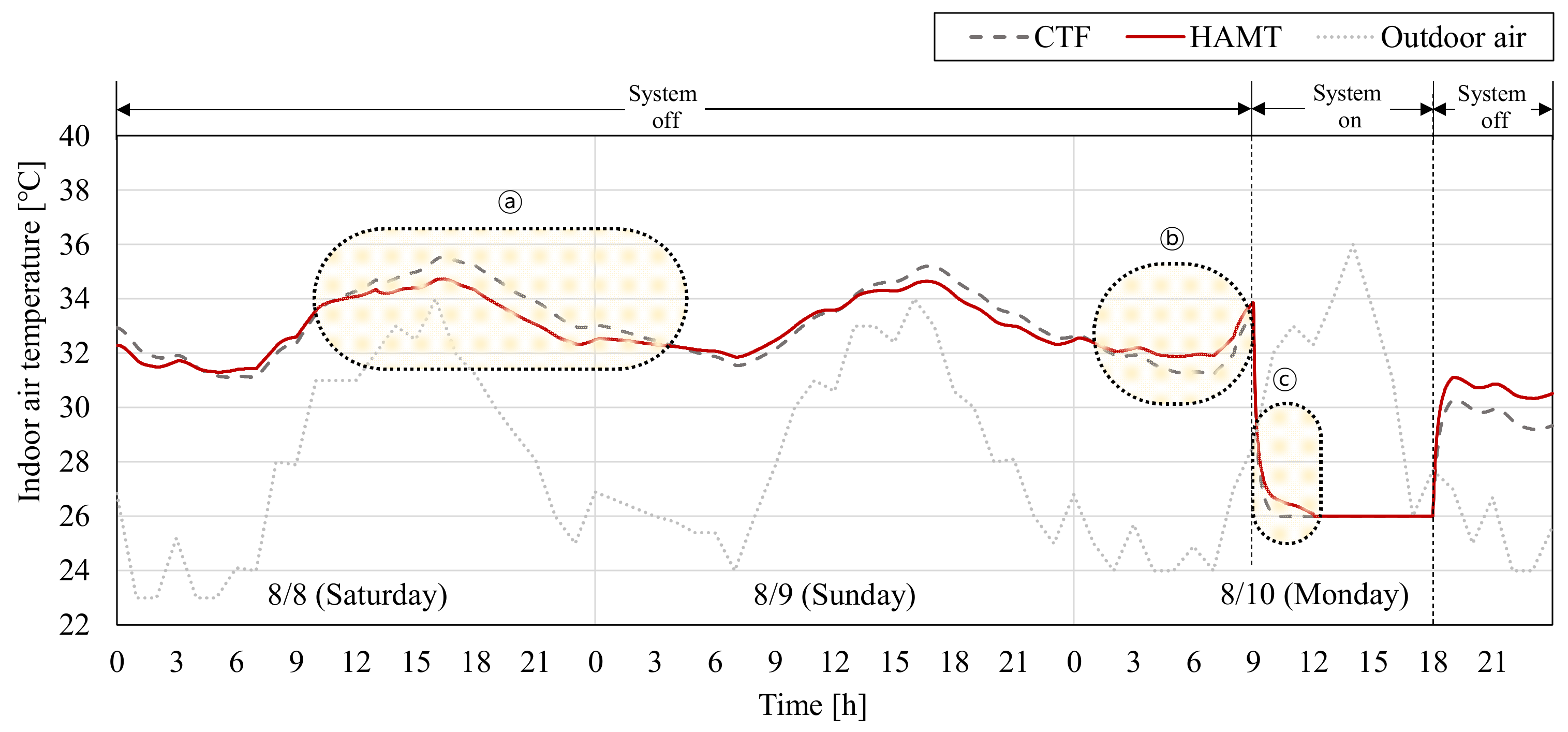
The heat balance algorithm is built in to the EnergyPlus and used to calculate the amount of the heat transferred from outdoors to indoors through the construction materials. This algorithm is divided into “conduction transfer function (CTF)” and “combined heat and moisture transfer (HAMT)” [17]. The CTF is a basic heat transfer algorithm used to calculate only sensible heat exchange and assumes that heat is not stored in the construction. Conversely, the HAMT is an algorithm used to calculate the total heat exchange and amount of heat stored in the construction.
This study selected the heat balance algorithm by comparing the simulation results of the CTF and HAMT to reflect the heat storage in the simulation. Figure 4 shows the change in indoor air temperatures according to the heat balance algorithm. As the CTF calculates the amount of sensible heat transfer without considering heat storage in the construction, the resulting CTF indoor air temperature changed rapidly according to the outdoor air temperature. However, as the HAMT calculates the amount of heat transfer considering heat storage, the change in the indoor air temperature was more gradual compared to the CTF (see ⓐ and ⓑ in Figure 4). Furthermore, the recovery time was increased to remove the stored heat at the beginning of the cooling system restart (see ⓒ in Figure 4). Therefore, to reflect heat storage accurately, this study conducted the simulation by applying the HAMT.

2.3. Determination of Simulation Cases

This study analyzed the effects of CLR and CSRT on the indoor thermal environment and energy consumption. Therefore, this study classified the simulation cases (see Table 2). The seven simulation cases used to evaluate the effect of changes in CLR had CLR values between 0.8 to 2.0, at an interval of 0.2. The CSRT for performing these simulations is 8:00 a.m., one hour before the occupancy start time. The five simulation cases used to evaluate the effect of changes in CSRT had a cooling system restart time from 7:00 a.m. to 9:00 a.m., at intervals of 30 min. The CLR value that was selected for these simulations was 1.2.

3. Results and Discussion

3.1. CLR

3.1.1. Indoor Thermal Environment

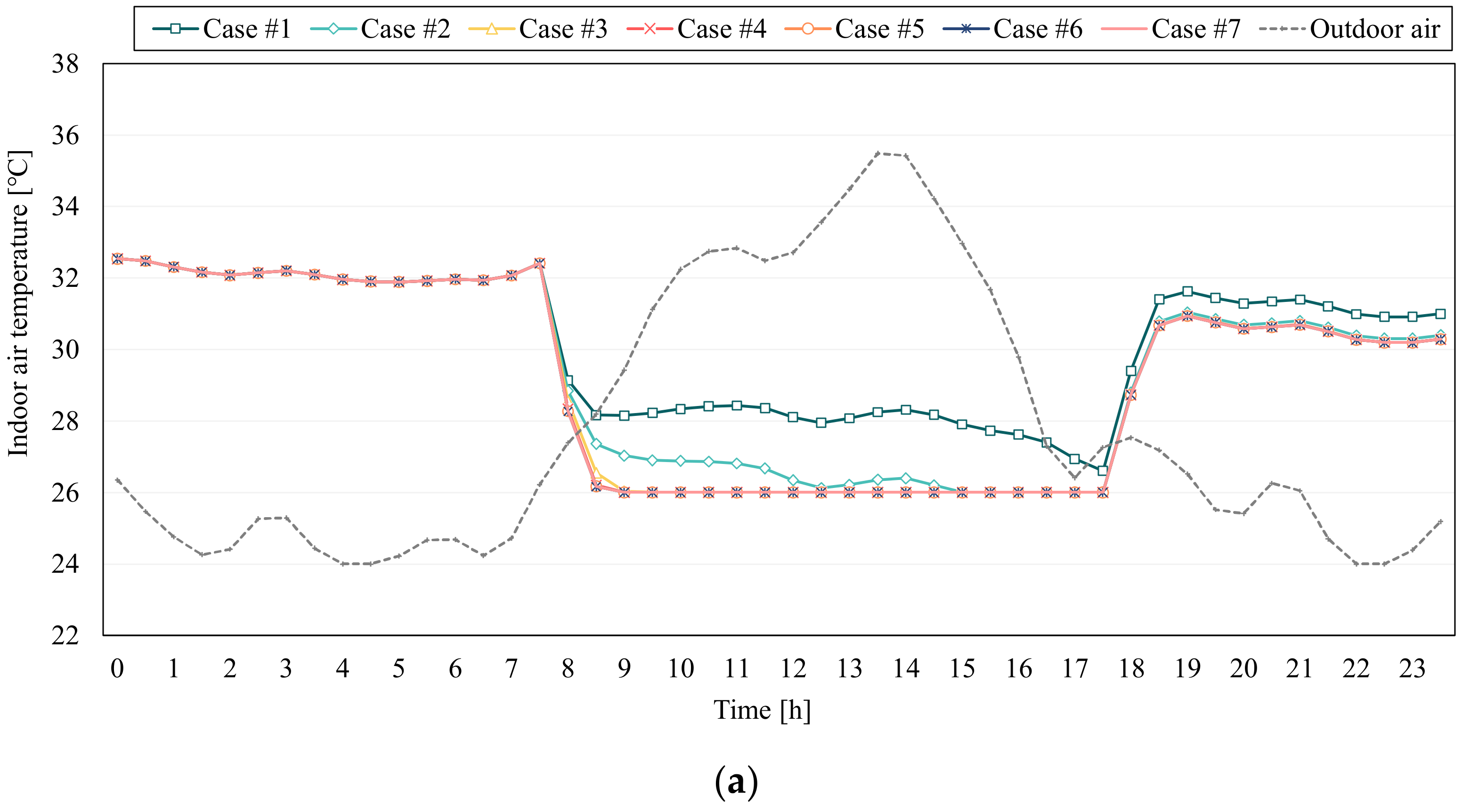
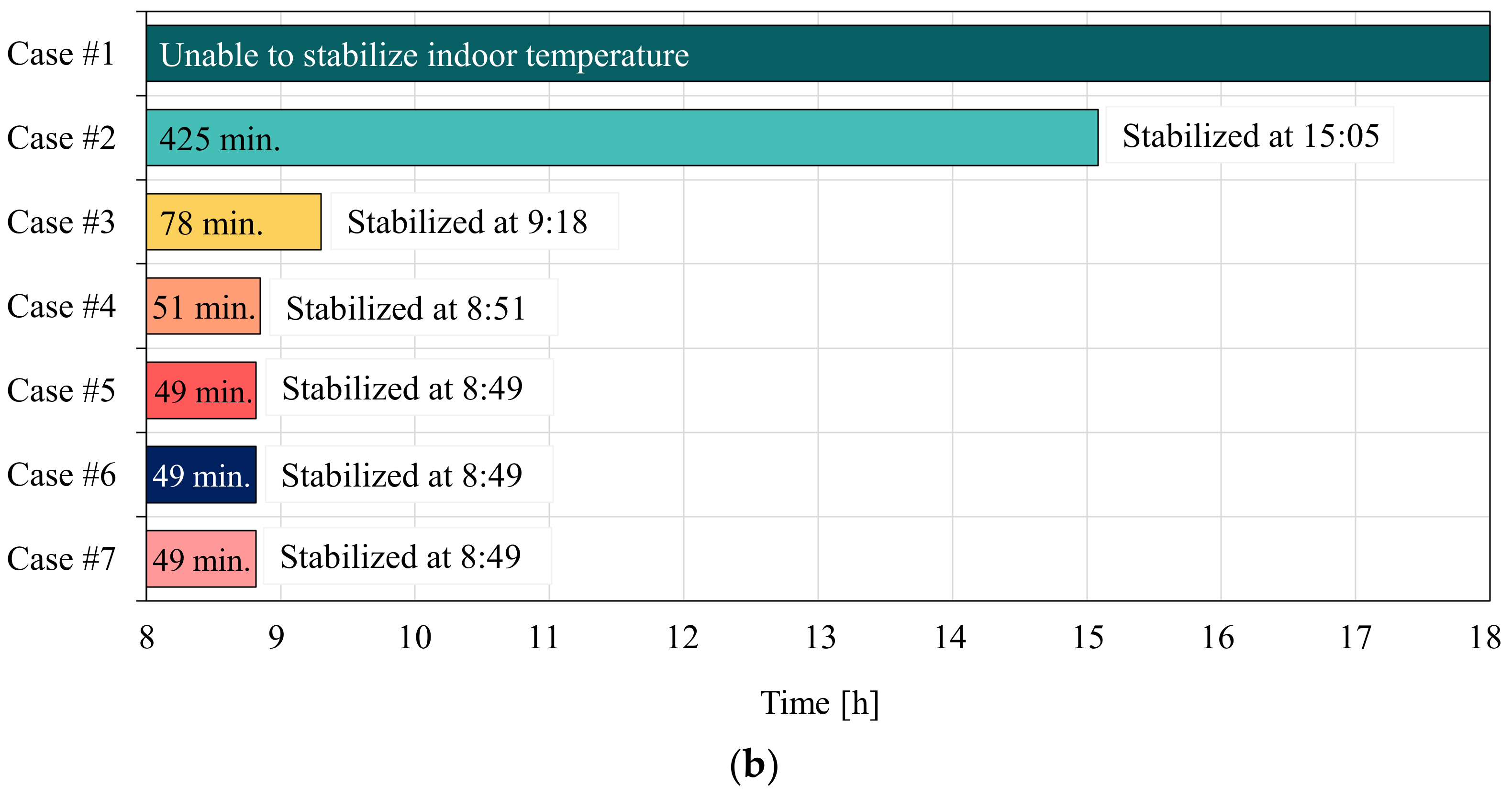
This study evaluated the indoor air temperature and recovery time to analyze the indoor thermal environment according to the CLR (see Figure 5). Figure 5a shows the change in indoor air temperatures according to different CLR values, while Figure 5b shows the recovery times obtained for the different CLR values. For case #1 (CLR 0.8), the indoor air temperature did not reach the cooling set-point temperature within the occupancy period. The recovery times of cases #2 (CLR 1.0), #3 (CLR 1.2), #4 (CLR 1.4), and #5–7 (CLR 1.6–2.0) were 425, 78, 51, 49 min, respectively (see Figure 5a,b). The recovery times decreased with increasing CLR values because capacity is related to an ability to remove accumulated loads. In addition, as the recovery times of cases #5–7 appeared the same, it may be considered that the effect of the capacity on the recovery time is insignificant when the CLR value is higher than 1.6. Therefore, in this study, the cooling system capacity should be set to CLR 1.2–1.6, with accurate capacity calculations, to prevent a worsening of the indoor thermal environment.

3.1.2. Energy Consumption

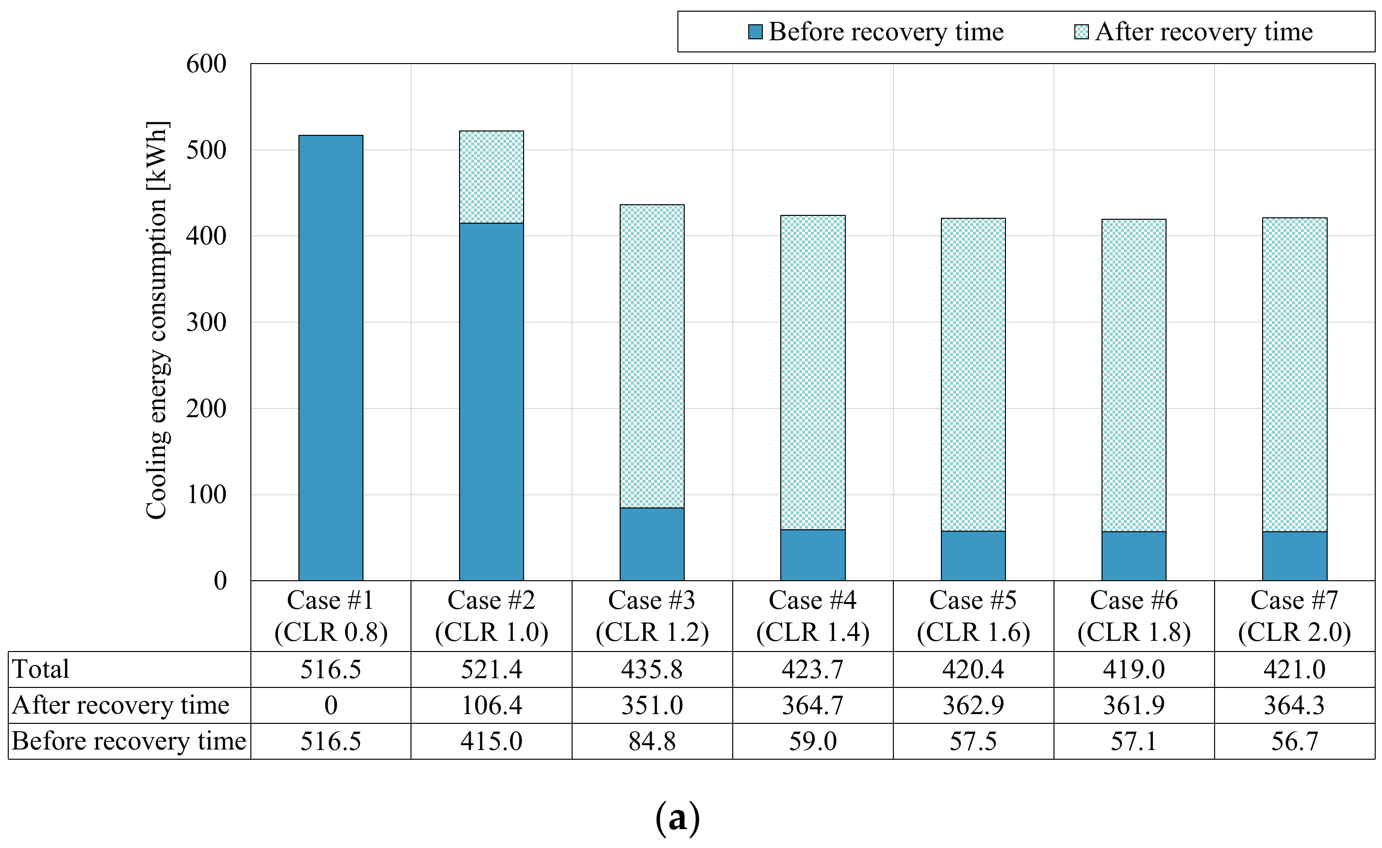
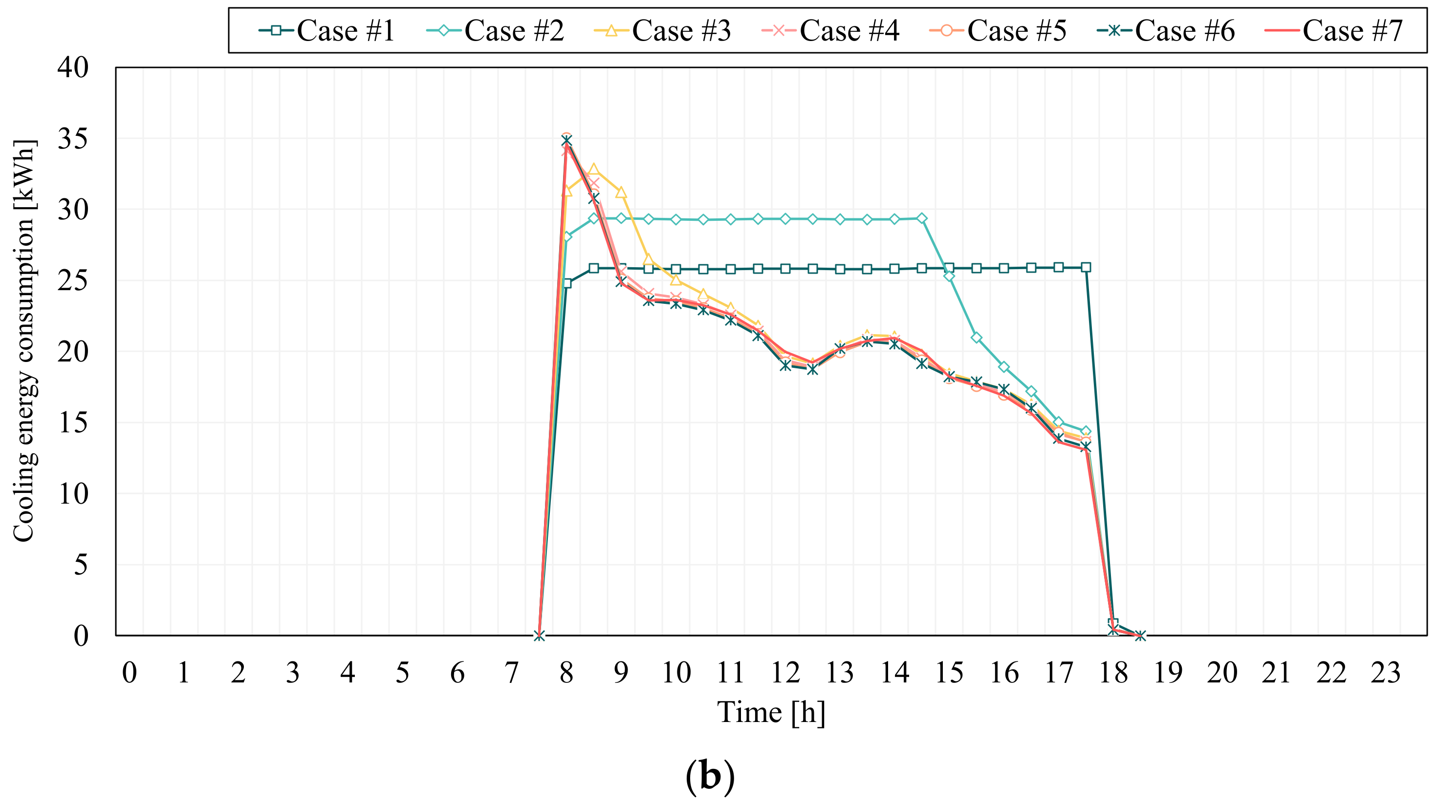
In this section, this study analyzed the energy consumption by varying the CLR values, as shown in Figure 6. Figure 6a shows the total energy consumption; Figure 6b shows changes in the energy consumption. The total daily energy consumptions for cases #1, #2, #3, #4, #5, #6, and #7 were 516.5, 521.4, 435.8, 423.7, 423.7, 420.4, 419.0, and 421.0 kWh. For cases #2–7, energy consumption before the recovery time decreased with increasing CLR values. For cases #2–6, energy consumption after the recovery time decreased with increasing CLR values. However, more energy was consumed for case #7 than for case #6 because the capacity was oversized in case #7 (see Figure 6a). For case #1, moreover, the capacity was undersized; the cooling system operated at full load during the occupancy period. For cases #2–6, an increasing CLR value, led to a reduction in the time in which the cooling system was operated at full load. The energy consumption patterns of cases #3–7, which showed similar recovery times, were also similar (see Figure 6b). The results of the analysis showed that the cooling system capacity should be determined to CLR 1.6–1.8 to reduce the energy consumption.

3.2. CSRT

3.2.1. Indoor Thermal Environment

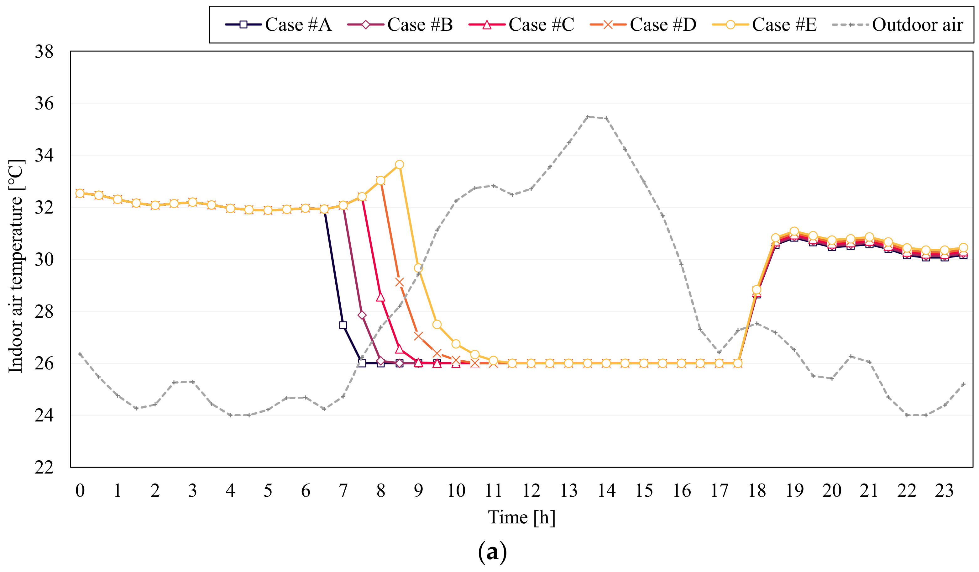
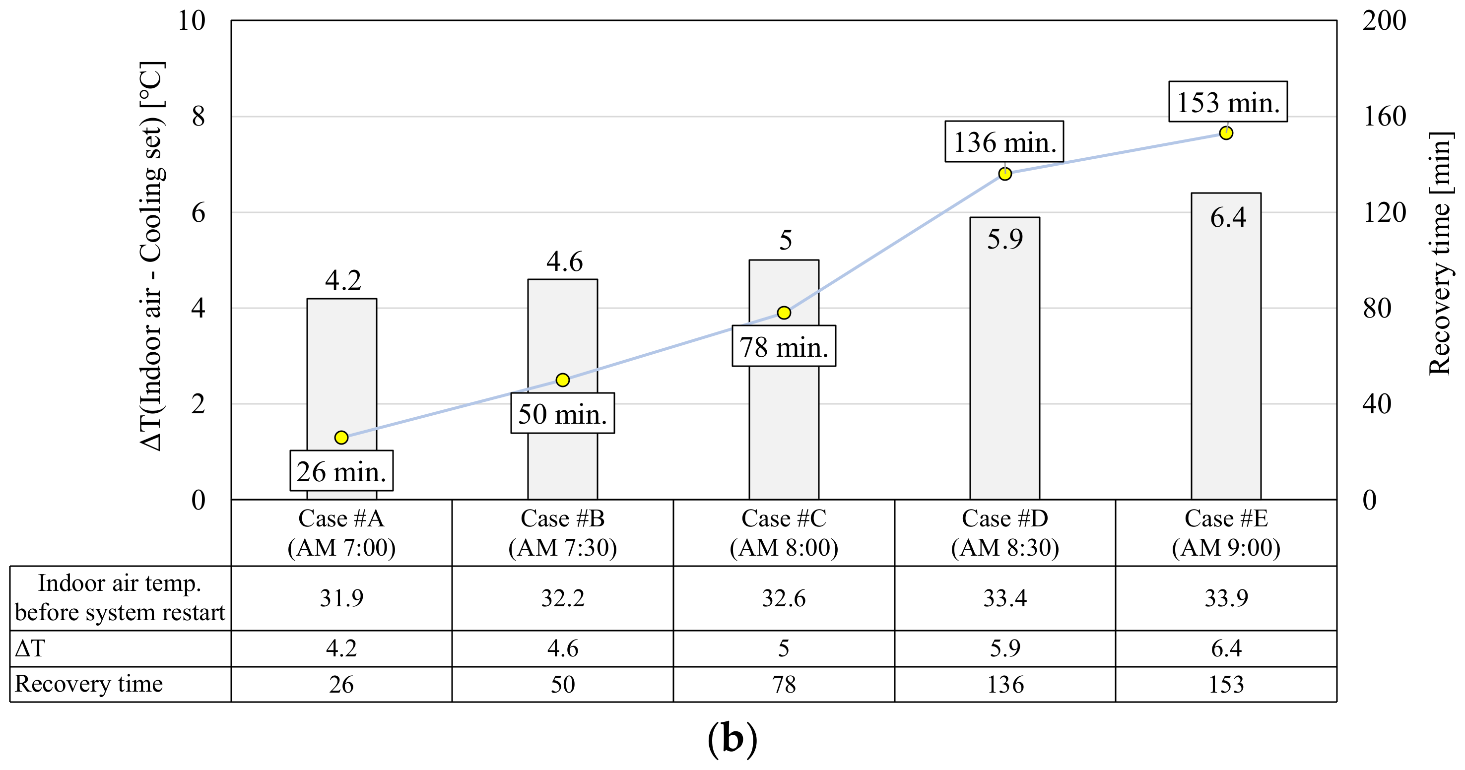
This study evaluated indoor air temperature and recovery time to analyze the effect of adjusting the CSRT on the indoor thermal environment, as shown in Figure 7. Figure 7a shows the change in indoor air temperatures over time; Figure 7b shows the temperature differences (indoor air-cooling set-point) and the recovery times obtained by varying CSRT. Before the cooling system was restarted, the indoor air temperature was distributed in the range 31.9–33.9 °C depending on the CSRT. As the CSRT was delayed, the indoor air temperature at the time which the cooling system was restarted increased (see Figure 7a). The recovery times of cases #A, #B, #C, #D, and #E were 26, 50, 78, 136, and 153 min, respectively. The results of a derivation of the recovery time showed that recovery time increased as CSRT was delayed. This is because the difference between the indoor air temperature and cooling set-point temperatures of cases #C, #D, and #E did not reach the cooling set-point temperature before the occupancy start time of 9:00 a.m. Therefore, to satisfy indoor thermal comfort by decreasing the indoor air temperature before the occupancy period begins, an appropriate CSRT should be determined with an evaluation of recovery time.

3.2.2. Energy Consumption

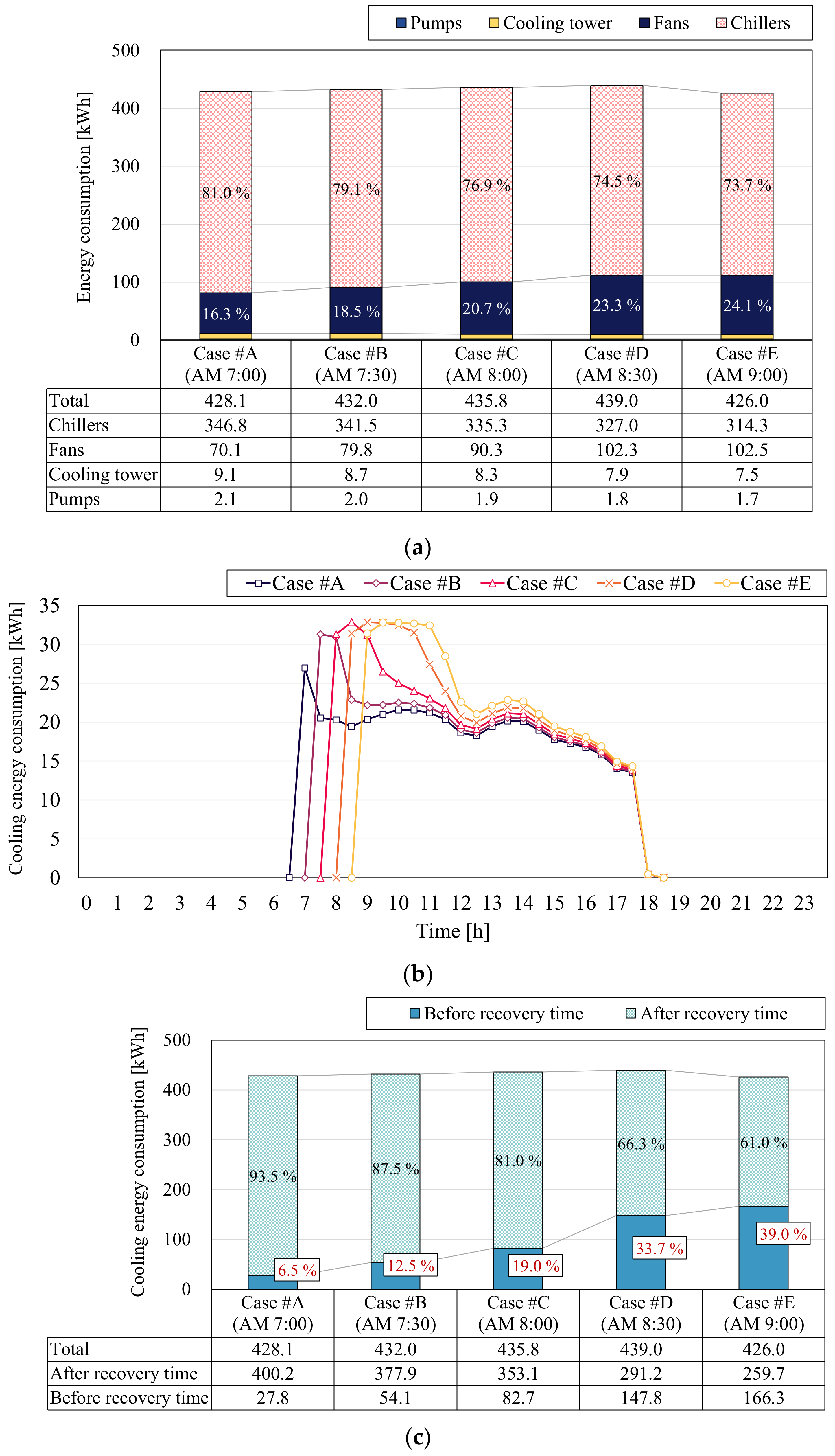
This study analyzed the energy consumptions by adjusting the CSRT, as shown in Figure 8. Figure 8a details the energy consumption of each cooling system component (chillers, fans, cooling tower, and circulation pumps); Figure 8b shows changes in the energy consumption over time; and Figure 8c shows the energy consumption before and after the recovery time. The total daily energy consumptions for cases #A, #B, #C, #D, and #E were 428.1, 432.0, 435.8, 439.0, and 426.0 kWh, respectively. In cases #A–D, the total daily energy consumption increased with a delayed CSRT. However, case #E showed the lowest energy consumption among the five cases. This is because, as the CSRT was delayed, the daily operating time of the cooling system decreased, and the energy consumptions of the chillers, cooling tower, and the pumps also decreased. However, the energy consumptions of the fans increased to reduce the indoor air temperature in cases in which the CSRT was delayed, as shown in Figure 8a. Moreover, delays in the CSRT led to increases in the indoor air temperature before the cooling system was restarted. Accordingly, at the beginning of the cooling system restart, the time at which the cooling system was operated at full load increased, as shown in Figure 8b. Furthermore, as the CSRT was delayed, the proportion of energy consumed before the recovery time increased. This is because the recovery time increased for later CSRTs (see Figure 8c). Therefore, to reduce unnecessary energy consumption, an appropriate CSRT should be selected by considering recovery times.

3.3. One-Week Ananlysis

The length of the system-off period due to the unoccupancy is different between Monday and other weekdays. The system-off period for Monday typically includes Saturday and Sunday. On the contrary, the system-off period for the other weekdays includes only one night. Because Section 3.1 and Section 3.2 showed results of the system-off period for Monday, this section shows those of other weekdays for analyzing the recovery time and daily energy consumption according to the difference in the length of the period. To achieve this, this study implemented the simulation for one week. The simulation period was 8 August (Saturday)–14 August (Friday), and the CLR value and CSRT of the simulation were set as 1.2 and 8:00 a.m., respectively.
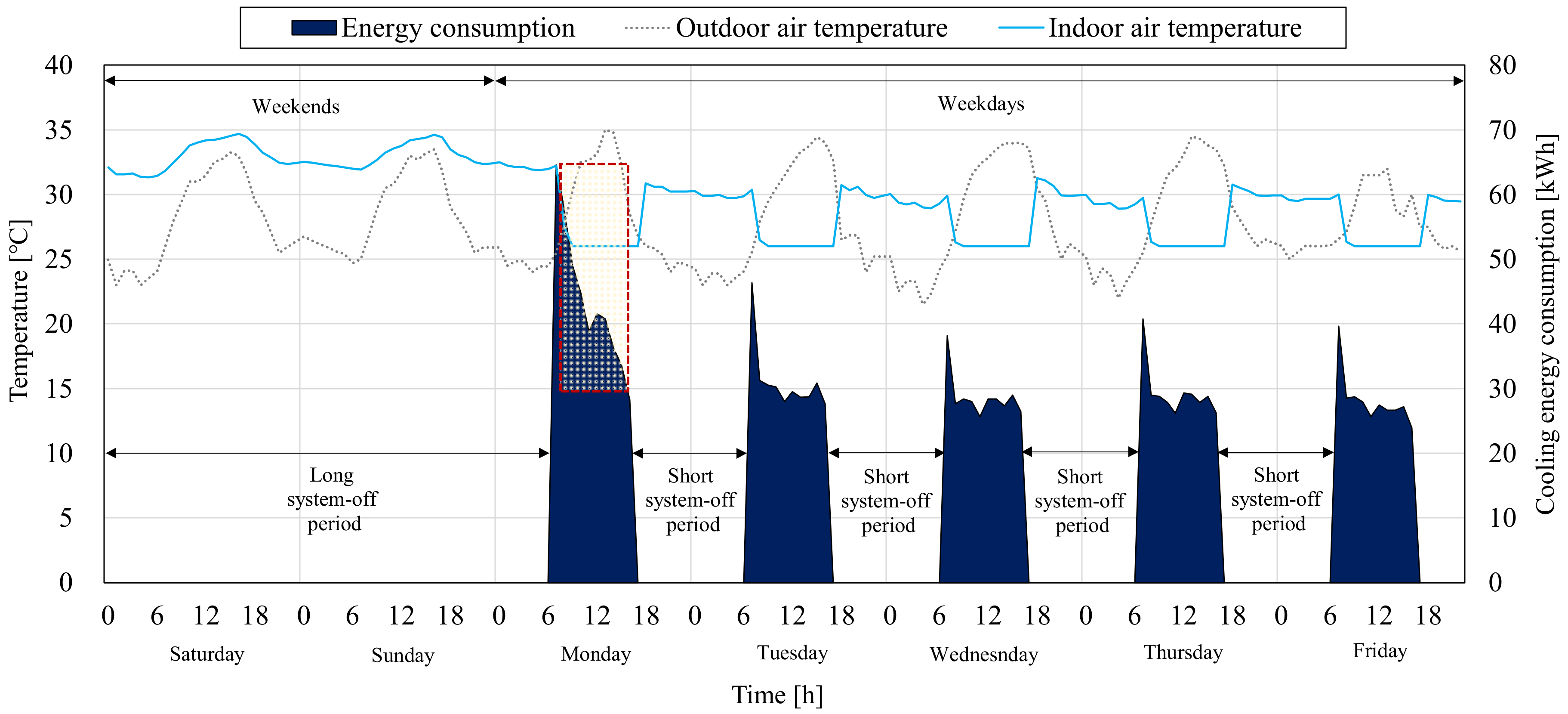
Table 3 shows the recovery time and daily energy consumption. Figure 9 shows the indoor and outdoor air temperatures and cooling energy consumption. The recovery time and daily energy consumption of Monday were 78 min and 435.8 kWh, the longest and highest results among the weekdays. The recovery time and daily energy consumption of the other weekdays varied between 14–22 min and 282.1–311.4 kWh, as the outdoor thermal environment was changed every day, but showed the similar results (see Table 3). These differences in the recovery time and daily energy consumption originate from the difference in the length of the system-off period between Monday and other weekdays (see Figure 9). On Monday, as the cooling system had to remove the heat accumulated during two days, more energy was consumed at the beginning of the cooling system restart than in the other days (see a dashed-line box in Figure 9). However, on the other weekdays, as the cooling system had to remove the heat accumulated during only one night (approximately 14 h), less energy was consumed. Therefore, because the result of the one-week analysis showed that the system-off period affects the recovery time and energy consumption, the daily optimal CSRT should be differently determined each day.

4. Conclusions

Because the CLR and CSRT are factors that affect the indoor thermal environment and energy characteristics, it is necessary to evaluate their impacts. This study analyzed the indoor thermal environments and cooling energy consumption by adjusting the CLR and CSRT. To achieve this, the simulation model was developed using EnergyPlus, and the energy simulation was implemented. Then, the simulation results were analyzed for the indoor thermal environment and energy characteristics, leading to the following conclusion.
(1)
Associated with the CLR, results evaluating the indoor air temperature, recovery time, and energy consumption are as follows.
Indoor thermal environment: In the case #1 (CLR 0.8), the indoor air temperature did not reach the cooling set-point temperature within the occupancy period (unmeasurable recovery time). In the case #2 (CLR 1.0), the indoor air temperature reached the cooling set-point temperature at 3:05 PM due to the excessive recovery time by the insufficient capacity. In the cases #3–7 (CLR 1.2–2.0), the indoor air temperature reached the cooling set-point temperature before 12:00 p.m. due to the recovery time decreased by sufficient capacity. When the CLR value was 1.6 or lower, as the CLR value decreased, the recovery time gradually decreased. However, when the CLR value exceeded 1.6, there was no difference in the recovery time. It should be noticed that when the CLR value was 1.6 or higher, there was no significant effect on the recovery time. In this study, therefore, to cool the indoor air temperature to the cooling set-point temperature before the occupancy start time, the cooling system capacity should be set to CLR 1.2 or higher. However, to prevent the cooling system capacity from being set excessively, the cooling system capacity should be set to CLR 1.2–1.6.
Energy characteristics: In cases #2–6 (cases where the indoor air temperature reached the cooling set-point temperature), as the CLR value increased, the daily energy consumption decreased because the operating time under full cooling loads was gradually reduced. However, in the case #7, daily energy consumption increased due to using the oversized cooling system. It should be considered that when the cooling system capacity was set to the CLR 2.0 or higher, the daily energy consumption tended to increase.
Therefore, in this study, the optimal cooling system capacity was CLR 1.6 to reduce the recovery time and prevent the cooling system capacity from being set oversized.
(2)
Associated with the CSRT, results evaluating the indoor air temperature, recovery time, and energy consumption are as follows.
Indoor thermal environment: Delays in CSRT led to an increase in the difference between the indoor air temperature and cooling set-point temperature before the cooling system was restarted, which cause an increase in the recovery time. Accordingly, in cases #3–5, the indoor air temperature did not reach the cooling set-point temperature before the occupancy start time. To decrease the indoor air temperature to the cooling set-point temperature before the occupancy start time, in this study, the CSRT should be determined before 8:00 a.m.
Energy characteristics: As the CSRT was delayed, the daily operating time of the cooling system decreased, and the energy consumption of the chiller, cooling tower, and pumps decreased. However, that of the fans increased. The proportion of energy consumed before the recovery time increased in the case of later CSRTs.
Therefore, to prevent the worsening of the indoor thermal environment and reduce the unnecessary energy consumption at the occupancy start time, in this study, the CSRT should be set to 7:30–8:00 a.m.
(3)
The results of the one-week analysis showed that the system-off period affected the recovery time and energy consumption. The recovery time and daily energy consumption of Monday were the longest and highest among the weekdays due to the accumulated heat that the cooling system should remove, which was larger than for other days. The recovery time and daily energy consumption of Tuesday-Friday were similar, as these had the same system-off period for 14 h.
Therefore, to achieve both the prevention of worsening of the indoor thermal environment and reduction in the unnecessary energy consumption, the optimal CSRT should be set differently every day.
As this study was based on a simulation, the results of these analyses might be different from the results of the actual cooling system. Therefore, additional verifications using actual buildings are recommended in the future. In addition, this study was conducted to analyze the system under intermittent operation according to occupied/unoccupied periods. Therefore, it is also recommended to compare the indoor thermal environment and energy characteristic by various CLR and CSRT against the cooling system continuously operated with a setback control method.

Author Contributions

All authors contributed equally to this study. Conceptualization, S.J., C.L. and S.D.; methodology, S.J. and S.D.; formal analysis, S.J., C.L. and S.D.; data curation, S.J., C.L. and S.D.; writing—original draft preparation, S.J. and S.D.; writing—review and editing, D.K., D.L. and S.D.; visualization, S.J., C.L., D.K., D.L. and S.D.; supervision, S.D. All authors have read and agreed to the published version of this manuscript.

Funding

This work was supported by the National Research Foundation of Korea (NRF) grant funded by the Korea government (MSIT) (No. 2021R1C1C1010231), the Korea Institute of Energy Technology Evaluation and Planning (KETEP) and the Ministry of Trade, Industry & Energy (MOTIE) of the Republic of Korea (No. 20204030200080).

Institutional Review Board Statement

Not applicable.

Informed Consent Statement

Not applicable.

Data Availability Statement

Not applicable.

Conflicts of Interest

The authors declare no conflict of interest.

Abbreviations

AHUair handling unit
ANNartificial neural network
ASHRAEAmerican society of heating, refrigerating and air-conditioning engineers
CLRcapacity-load ratio
CSRTcooling system restart time
CTFconduction transfer function
Cv(RMSE)coefficient of variation of the root mean square error
HAMTcombined heat and moisture transfer
HVACheating, ventilation, and air conditioning
IWEC2International weather files for energy calculation 2.0
MBEmean bias error
PIRpassive infrared
SHGCsolar heat gain coefficient
VAVvariable air volume
VRFvariable refrigerant flow
WWRwindow-to-wall ratio

References

  1. Jang, H.I.; Suh, S.J. Analysis of Indoor Thermal Environment and Energy Consumption in Office Building Controlled by PMV. J. Korean Sol. Energy Soc. 2013, 133, 15–22. [Google Scholar] [CrossRef]
  2. Yang, I.H.; Yeo, M.S.; Kim, K.W. Application of artificial neural network to predict the optimal start time for heating system in building. Energy Convers. Manag. 2003, 44, 2791–2809. [Google Scholar] [CrossRef]
  3. Fadzli Haniff, M.; Selamat, H.; Yusof, R.; Buyamin, S.; Sham Ismail, F. Review of HVAC scheduling techniques for buildings towards energy-efficient and cost-effective operations. Renew. Sustain. Energy Rev. 2013, 27, 94–103. [Google Scholar] [CrossRef]
  4. Moon, J.W.; Jung, S.W. Development of a thermal control algorithm using artificial neural network models for improved thermal comfort and energy efficiency in accommodation buildings. Appl. Therm. Eng. 2016, 103, 1135–1144. [Google Scholar] [CrossRef]
  5. Lee, C.; Koo, J. Development of Simulation Model Based Optimal Start and Stop Control Daily Strategy. Korea Soc. Geotherm. Energy Eng. 2018, 14, 16–21. [Google Scholar]
  6. Tang, R.; Wang, S.; Shan, K.; Cheung, H. Optimal control strategy of central air-conditioning systems of buildings at morning start period for enhanced energy efficiency and peak demand limiting. Energy 2018, 151, 771–781. [Google Scholar] [CrossRef]
  7. Jang, J.; Baek, J.; Leigh, S.B. Prediction of optimum heating timing based on artificial neural network by utilizing BEMS data. J. Build. Eng. 2019, 22, 66–74. [Google Scholar] [CrossRef]
  8. Park, S.; Ahn, K.U.; Hwang, A.; Choi, S.; Park, C.S. Artificial Neural Network Models for Optimal Start and Stop of Chiller and AHU. J. Archit. Inst. Korea Struct. Constr. 2019, 35, 45–52. [Google Scholar]
  9. Shin, M.S.; Rhee, K.N.; Jung, G.J. Optimal heating start and stop control based on the inferred occupancy schedule in a household with radiant floor heating system. Energy Build. 2020, 209, 109737. [Google Scholar] [CrossRef]
  10. Yang, I. Optimization of operation times of a heating system in office building. J. Asian Archit. Build. Eng. 2020, 19, 400–415. [Google Scholar] [CrossRef]
  11. Lee, Y.; Kim, W. Development of an Optimal Start Control Strategy for a Variable Refrigerant Flow (VRF) System. Energies 2021, 14, 271. [Google Scholar] [CrossRef]
  12. DOE. EnergyPlus Version 9.3; Department of Energy (DOE): Washington, DC, USA, 2020.
  13. DOE. Commercial Prototype Building Models; Department of Energy (DOE): Washington, DC, USA, 2019.
  14. MOLIT. Standard of Building Energy Saving; Ministry of Land, Infrastructure and Transport (MOLIT): Sejong City, Korea, 2018.
  15. KEA. Building Energy Efficiency Certification; Korea Energy Agency (KEA): Ulsan, Korea, 2021. [Google Scholar]
  16. ASHRAE. International Weather for Energy Calculations; Version 2.0; American Society of Heating, Refrigerating and Air-Conditioning Engineers (ASHRAE): Atlanta, GA, USA, 2017. [Google Scholar]
  17. DOE. EnergyPlus Documentation: Input Output Reference; Department of Energy (DOE): Washington, DC, USA, 2020.
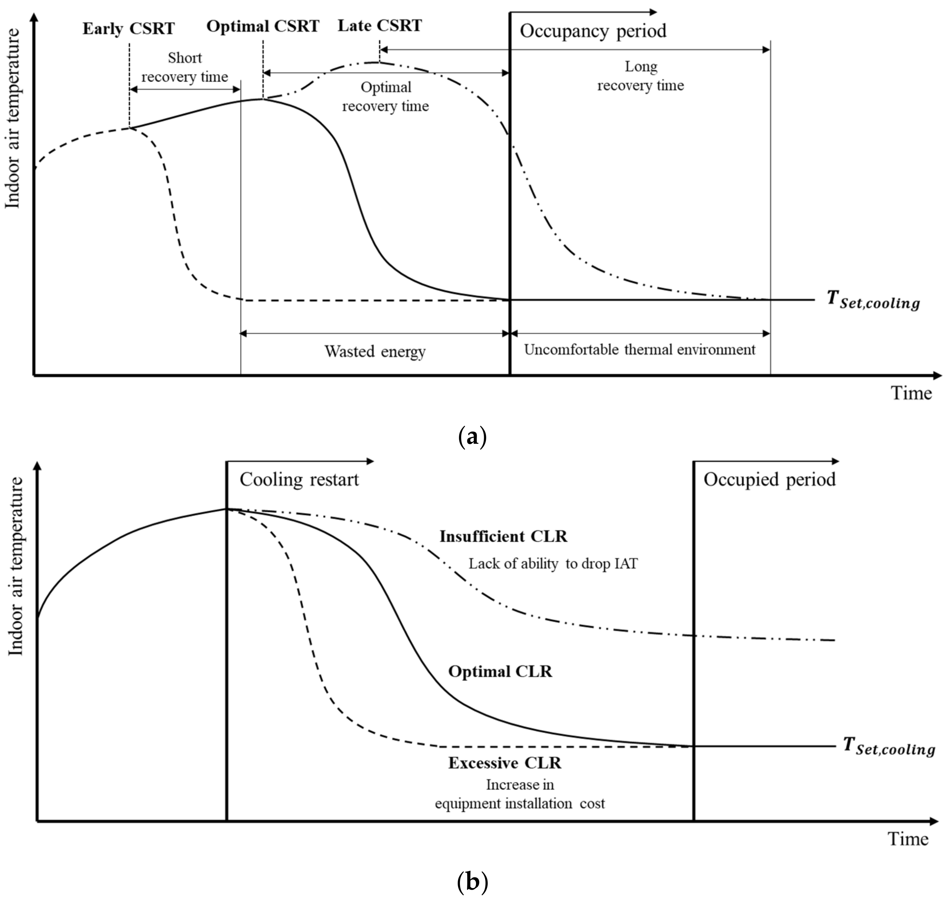
Figure 1. The effect of varying (a) cooling system restart time (CSRT), and (b) capacity-load ratio (CLR) on indoor air temperature.
Sustainability 14 09392 g001
Figure 2. Overall research diagram.
Sustainability 14 09392 g002
Figure 3. Schematic diagrams of the referenced simulation model. (a) 3D view of building, and (b) simplified HVAC system.
Sustainability 14 09392 g003
Figure 4. Comparison of indoor air temperatures obtained using the conduction transfer function (CTF) and combined heat and moisture transfer (HAMT).
Sustainability 14 09392 g004
Figure 5. Change in indoor thermal environments when varying CLR values. (a) Change in indoor air temperatures, and (b) recovery times for CLR cases.
Sustainability 14 09392 g005aSustainability 14 09392 g005b
Figure 6. Evaluation of energy consumption with varying CLR values. (a) Total energy consumption, and (b) changes in energy consumption.
Sustainability 14 09392 g006aSustainability 14 09392 g006b
Figure 7. Evaluation of indoor thermal environments according to various CSRT values. (a) Changes in indoor air temperature, and (b) temperature differences and recovery times.
Sustainability 14 09392 g007aSustainability 14 09392 g007b
Figure 8. Evaluation of energy consumptions according to various CSRTs. (a) Detailed energy consumptions, (b) changes in energy consumption over time, and (c) energy consumptions before and after the recovery time.
Sustainability 14 09392 g008
Figure 9. Indoor and outdoor air temperatures, and cooling energy consumption during one week.
Sustainability 14 09392 g009
Table 1. Summary of the input parameters used for building modeling.
Input ParametersValuesReferences
Building typeOfficeEnergyplus commercial
prototype building model [13]
Building volume4800 m3
Window area158.4 m2
ConstructionsExterior wallRed brick0.12 W/m2·KStandard of building energy saving [14]
Timber
Insulation
Timber
Gypsum board
WindowSimple glazing1.50 W/m2·K
Solar heat gain coefficient (SHGC)0.36
ShadingNo
RoofAsphalt looping0.12 W/m2·K
Timber
Insulation
Timber
Gypsum board
FloorConcrete0.17 W/m2·K
Insulation
Mortar
Flooring
Cooling set-point temperature26 °CBuilding energy efficiency certification [15]
Occupancy periodWeekdays9:00 a.m.~6:00 p.m.
WeekendsAlways off
Weather dataDaejeon, KoreaInternational weather files for energy calculation [16]
HVAC systemVAV system
Heat source equipmentChiller Cooling tower
Heat balance algorithmHAMT
Table 2. Summary of the input parameters used for simulation cases.
Simulation ScenariosSimulation CasesControl ParametersBase-Case
CLR Values
(Capacity)
Cooling System
Restart Time
CLR#10.8 (78 kW)
#21.0 (97 kW)
#31.2 (117 kW) √ (for CSRT simulation)
#41.4 (136 kW)
#51.6 (156 kW)
#61.8 (175 kW)
#72.0 (195 kW)
CSRT#A 7:00 a.m.
#B 7:30 a.m.
#C 8:00 a.m.√ (for CLR simulation)
#D 8:30 a.m.
#E 9:00 a.m.
Table 3. Recovery time and daily energy consumption by day.
MondayTuesdayWednesdayThursdayFriday
Recovery time(min)7822141716
Daily energy
consumption
(kWh)435.8311.4287.3293.8282.1
Publisher’s Note: MDPI stays neutral with regard to jurisdictional claims in published maps and institutional affiliations.