Abstract
Foamed asphalt recycling technology can effectively recover waste asphalt pavement materials and achieve the sustainable utilization of resources. This technology’s core equipment is asphalt foaming equipment. Since the asphalt foaming device’s fault data are uncertain, this work proposes a method for evaluating the device’s reliability, combining triangular intuitionistic fuzzy numbers, trapezoidal intuitionistic fuzzy numbers, and expert knowledge. Using the proposed evaluation method, the failure probability of the asphalt foaming device and the importance of the bottom event were calculated. The obtained model results were found to be consistent with the actual collected data, verifying the reliability and validity of the model. Furthermore, the asphalt viscosity is one of the key factors affecting the asphalt foaming recycling technology. In this work, the influence of different viscosities on the asphalt foaming mechanism was investigated using a theoretical analysis. Then, a computational fluid dynamics (CFD) analysis method was employed to simulate the different viscosity asphalt foaming processes, aiming to identify the most suitable one for the production of high-quality foam asphalt in the foaming asphalt viscosity range. Finally, experiments were carried out to verify the results of the analysis. The results show that the asphalt foaming device’s failure probability was around 7.512 × 10⁻², and the best foaming asphalt viscosity was in the range of 0.3~0.5 Pa·s.
1. Introduction
According to the statistics of China’s Ministry of Transport in April 2022, the reported total length of roads in China was around 5.28 million kilometers. A total of 1.29 trillion yuan has been spent on maintenance since the implementation of the 13th Five-Year Plan. This includes conducting preventive maintenance on 1.356 million kilometers of road, repair and maintenance on 1.652 million kilometers of road, and safety and life protection projects on 1.16 million kilometers of road. Conventionally, the traditional method of highway maintenance in China involves throwing away the waste asphalt pavement materials directly. This is not only caused a large waste of resources but also contributed to the pollution of the ecological environment, which is in turn against the principle of sustainable development in China. In its 14th Five-Year Plan, China has clearly proposed promoting the high-quality development of highway maintenance management, and vigorously advocates for coordinated and sustainable development. Foamed asphalt recycling technology has been widely adopted by the global highway community because of its unique technical advantages, including good environmental performance, low cost and sustainability.
Foamed asphalt recycling technology is being applied in Europe, Southeast Asia, South Africa, Asia, and Australia, achieving significant economic and environmental benefits [1,2,3,4,5]. As equipment for preparing foamed asphalt, an asphalt foaming device plays a vital role in this domain. Since foamed asphalt recycling technology has widespread applications, many scholars are studying foamed asphalt. These studies have focused—for example—on foamed asphalt’s performance [6,7,8], the influence of foaming parameters [9,10,11], and the development of asphalt foaming equipment [12,13,14]. Nevertheless, the current studies have not evaluated the reliability of the asphalt foaming device and in China, there are few studies on the optimum foaming viscosity of asphalt in the foaming regeneration technology of asphalt.
Fault tree analysis (FTA) is a method for evaluating a system’s reliability and safety. The tree enables a gradual top-down analysis of the causes of system failure, identifying component-level failures reflected at the system level. It has been applied in many fields, including aerospace, nuclear energy, and machinery [15,16,17,18]. Traditional FTA relies on the probability of the lowest-level event’s occurrence. However, in real-world applications, it is often difficult to accurately assess basic events’ probability. This problem can be mitigated by relying on fuzzy theory to handle the uncertainties. Zadeh was the first to introduce the concept of a fuzzy set [19], while Tanaka et al. applied the fuzzy set theory to FTA [20]. Since then, the research and applications of fuzzy sets have received extensive attention [21,22,23].
In recent years, many scholars have applied fuzzy sets to FTA. Since traditional fault trees cannot capture the events’ dynamic behavior, Kabir et al. proposed a method that integrates expert heuristics and fuzzy set theory with the Pandora temporal fault tree. This method supports the FTA of dynamic systems with uncertain data and enables the quantitative analysis of temporal fault trees [24,25]. Kumar and Sharma used several types of intuitionistic fuzzy numbers (IFN) to quantify the uncertainty of the liquefied natural gas terminal emergency shutdown system’s failure data. The authors used arithmetic operations on IFN to evaluate the system’s failure intervals at different levels [26]. Lin et al. developed a safety assessment method for the high-speed train bogie. Their method is based on the hesitant interval-valued intuitionistic fuzzy set and was shown to improve the accuracy of the system’s safety evaluation [27]. Zarei et al. proposed a hybrid dynamic human factor model that builds on the human factor analysis and classification system, intuitionistic fuzzy set theory, and the Bayesian network. This derived model was tested on a natural gas pipeline [28]. Yazdi utilized a Bayesian update mechanism to handle the dynamic structure, while the intuitionistic fuzzy number 2-tuple fuzzy set was used to deal with the subjectivity of uncertainty processing [29]. The components’ aging motivated Hermansyah et al. to employ a fuzzy FTA method to evaluate the performance of the Siwabessy multipurpose reactor’s primary cooling system [30].
Liu et al. proposed a fuzzy evaluation method that integrates the interval-valued intuitionistic fuzzy sets, prospect theory, and improved D number [31]. Qiao et al. integrated intuitionistic fuzzy set theory and a Bayesian network into a new human factor analysis framework. The resulting model enables comprehensive dynamic human factor analysis and is characterized by flexibility and uncertainty processing [32]. Zhang et al. utilized fuzzy set theory and FTA to calculate the pipelines’ failure probability [33]. Li et al. established an FTA model in which the triangular fuzzy number is used to describe the reducer’s fault cause’s probability. This study calculates the reducer’s fuzzy failure probability and discusses the fault cause’s fuzzy importance measure [34]. Meng et al. utilized the triangular fuzzy number method to establish the fault tree of accidents involving motor vehicles in urban road sections and determined three major accident causes [35]. For more research on fuzzy set fault analysis methods, please refer to [36,37,38,39,40,41].
At present, there are three methods to study fluid mechanics: experimental study, theoretical analysis and CFD simulation analysis. The experimental research method has the disadvantages of a long duration, low efficiency and high cost. Theoretical analysis is universal, but it is difficult to find the theoretical basis when faced with complex models. The CFD simulation analysis technology has the advantages of low cost, a short cycle, and the ability to provide conditions that cannot be simulated by real experiments. It has been widely used in complex fluid analysis in aerospace, ships, wind, water conservancy and other fields [42,43,44,45]. However, due to the complexity of the physical process and people’s cognitive bias, there are many uncertain factors in CFD simulation analysis technology, such as model parameters, numerical discretization, model form and so on, which bring great challenges to the credibility evaluation of CFD numerical simulations. In order to analyze the optimal viscosity range of asphalt during asphalt foaming, the method of combining the three will be adopted in this paper: theoretical analysis–CFD simulation analysis–theoretical analysis–CFD simulation analysis–experimental verification
To summarize, many scholars have tackled the problem of uncertain reliability assessment by integrating the intuitionistic fuzzy sets and fault trees. Prompted by the fuzzy probability of the asphalt foaming device’s basic events’ occurrence, this work uses a method that combines the triangular intuitionistic fuzzy number, trapezoidal intuitionistic fuzzy number, and expert opinions to evaluate the asphalt foaming device’s reliability. The heterogeneous expert group is used to evaluate the opinions of other experts, effectively managing the expert opinions’ subjectivity. Simultaneously, the aggregation algorithm synthesizes the experts’ opinions, and the Delphi method is utilized to optimize the expert weights. The results obtained by the model are consistent with the actual situation, which verifies the reliability and validity of the model. This paper builds on these studies to provide a reference for conducting reliability evaluation in the domain of asphalt foaming devices. Finally, the influence of different viscosities of asphalt on foaming effects is obtained by the CFD analysis method, and the viscosity range of foamed asphalt which is most suitable for producing high-quality foamed asphalt is found to improve the stability and utilization rate of foamed asphalt recycling technology, and the analysis results were verified by experiments.
2. Methods
2.1. Fuzzy Number Theory
Let U denote a domain composed of certain elements. Then, a fuzzy set is a pair (U, A(x)) where A(x) is a membership function , which maps the elements in U to real numbers in the [0,1] interval. Thus, represents the relationship between element and a fuzzy set , , and is referred to as the membership degree of to . The higher the value of , the stronger the belonging of to .
Common membership functions include triangular fuzzy numbers, trapezoidal fuzzy numbers, and normal fuzzy numbers. The triangular fuzzy numbers have high efficiency and a simple form, but the trapezoidal fuzzy numbers are more accurate. Both triangular and trapezoidal fuzzy numbers are frequently utilized in fuzzy fault trees. Due to the asphalt foaming device’s real-world working environment, this paper synthesizes triangular and trapezoidal fuzzy numbers to improve the fuzzy accuracy.
The membership function of the triangular fuzzy number is expressed as:
Therefore, and are the lower- and upper-value limits and is the value with the greatest likelihood. The triangular fuzzy numbers’ membership function is graphed in Figure 1.
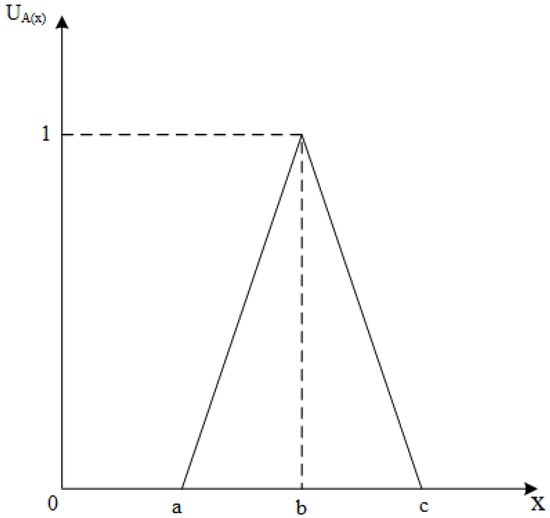
Figure 1.
The triangular fuzzy numbers’ membership function.
The membership function of the trapezoidal fuzzy number is defined as:
and its graph is shown in Figure 2.
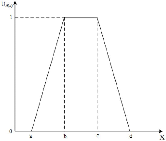
Figure 2.
The trapezoidal fuzzy numbers’ membership function.
Fuzzy mathematics converts the uncertain factors into interval values, and such a mapping is defined using the membership function. Thus, a membership function forms the basis for a fuzzy fault tree. In engineering systems, the membership function is often determined by expert judgment and weighted average, and the risk value is expressed as a fuzzy probability.
2.2. Fuzzification of the Fault Tree
Due to the subjectivity of expert judgment, it is not appropriate to use the average method to synthesize expert opinions. In order to reduce the subjectivity of expert opinions, the aggregation algorithm is used to synthesize the opinions of different experts, and the expert judgment is described by natural language variables, so that the consistency of expert judgment language is calculated, and the characteristics of a fuzzy and inaccurate intersection of expert judgment language are overcome. When the probability of the basic event is not accurate, the expert judgment method can effectively solve this problem.
First, each expert judges the basic event. The resulting natural language variables are then mapped onto the corresponding fuzzy numbers, enabling fuzzy probability estimation. The formal steps are as follows:
(1) Calculate the similarity between the opinions of a pair of experts on Ei and Ej. Let S(Ai, Aj)denote the similarity between Ai and Aj. Then,
where , and are two standard fuzzy numbers, and and represent ’s and ’s mathematical expectations. In the case of trapezoidal fuzzy numbers, it follows that:
where , .
(2) Construct the consistency matrix, denoted as , and calculate the average consistency measure A(Ei) for each expert Ei(i = 1, 2, …, n).
where Sij = S(Ai, Aj). If i = j, then Sij = 1. Thus, A(Ei) is obtained as:
(3) Calculate the relative agreement RA for each expert Ei:
(4) Calculate the relative consistency coefficient ωi for each expert following:
where is the relaxation factor that indicates the ’s and ’s importance for . is determined using the Delphi method, which is introduced in Section 2.5.
(5) Synthesize the experts’ views using:
where is the aggregated fuzzy number of the system’s lowest-level event , is expert ‘s fuzzy number for , is the number of the system’s bottommost events, and is the weight factor for expert .
(6) Estimate the fuzzy possibility
The uncertainty of the asphalt foaming device’s basic event probability renders the error reduction and reliability improvement crucial. Thus, the basic event’s fuzzy probability data are used to quantify the fault tree. Following the fuzzy mathematical principles, the top event is fuzzified and combined with the fault tree logic and the minimum cut set algorithm. The following expressions are obtained:
For triangular fuzzy numbers, the fuzzy possibility of the logic AND gate is:
while that for the logic OR gate equals:
In the case of trapezoidal fuzzy numbers, the fuzzy possibilities are:
for the logic AND gate and
for the logic OR gate. The fuzzy possibility minimum cut set of a top event can be expressed as:
where represent the fuzzy possibilities of all minimum cut sets.
2.3. Fault Tree Defuzzification
To obtain the top event’s exact probability, the fuzzy possibility of the fault tree event must be converted into the crisp possibility score (CPS) via defuzzification. This process transforms the fuzzy language into real output.
2.3.1. Defuzzification Output
Security analysts first need to select appropriate defuzzification techniques for their research fields to enable fuzzy probabilities’ defuzzification. Numerous defuzzification techniques are available in the fuzzy fault tree domain, including the maximum mean membership method, the center of gravity method, the weight coefficient method, and the maximum central region method. Due to its simplicity and efficiency, this paper utilizes the center of area method to obtain the fuzzy possibility scores.
The defuzzification of the triangular fuzzy number is defined as:
where is the defuzzification output and is the output variable.
Similarly, trapezoidal fuzzy number ’s defuzzification is defined as:
2.3.2. Calculate the Probability of the Top Event
The traditional fault tree system failure results in an exact value. In contrast, the output generated by the fuzzy fault tree method is a possible value. This difference stems from the fuzziness in quantifying the basic event’s failure probability using fuzzy language variables. The fuzzy possibility score needs to be processed and further transformed to obtain the system’s top event’s probability. The calculation formula is as follows:
where , and is the probability of the top event’s occurrence.
2.3.3. Fuzzy Importance Analysis
Fuzzy importance indicates that if basic event has never failed, the occurrence probability of the top event accounts for the proportion of the original failure probability. To make the data more intuitive, the following expression is commonly utilized for fuzzy importance calculation:
where represents the total fuzzy probability of failure when of a certain bottommost event that never fails.
2.4. Expert Opinion
The probability value or quantitative data on the system components are required to evaluate the system’s reliability. In real-world applications, such data might not always be obtainable for all system components. In that case, experts’ opinions can be collected and used in system reliability analysis. To capture the experts’ opinions on the bottommost events’ probabilities, this paper divides the language scale into seven levels: very low (VL), low (L), medium-low (ML), medium (M), medium-high (MH), high (H), and very high (VH). Further, the triangular fuzzy number and trapezoidal fuzzy number are combined to determine the natural language value. The fuzzy number graph for the natural language is shown in Figure 3.
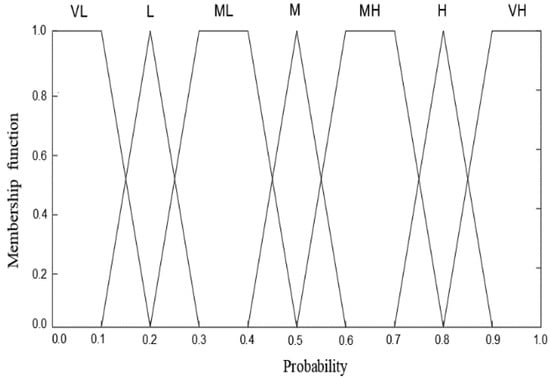
Figure 3.
Fuzzy number graph representing expert opinion variables.
2.5. Expert Weight
The Delphi method proposes forming a panel of several domain experts, who then express their opinions on a particular research objective or a problem [46]. During the evaluation process, the experts can communicate with the researchers only (i.e., they cannot consult each other), which ensures the independence of expert opinions. The expert opinions are statistically analyzed, enabling the researchers to make quantitative judgments [47,48]. It is widely used in both academia and projects and commonly serves for quantifying uncertainties.
Before determining the experts’ weights, it is necessary to develop the weight index. Within this work, four main aspects are considered: the degree of expert education (EE), information source (IS), expert professional position (PP), and relevant experience (RE). The expert weight calculation process is shown in Figure 4. The flow chart of the reliability analysis method is shown in Figure 5 and flow chart of the asphalt viscosity analysis is shown in Figure 6.
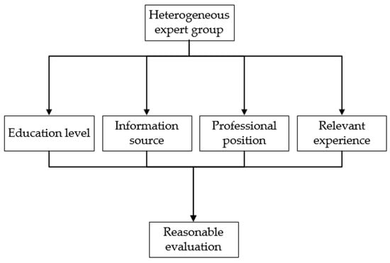
Figure 4.
Expert weight calculation process.
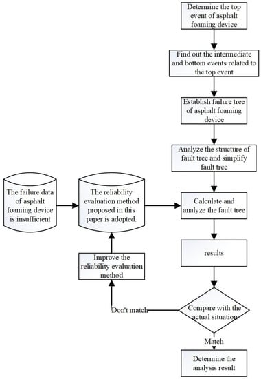
Figure 5.
Flow chart of the reliability analysis method.

Figure 6.
Flow chart of the asphalt viscosity analysis.
3. Case Study
3.1. Asphalt Foaming Device
This paper studies the asphalt foaming device developed by Chang’an University. This device is composed of six subsystems: an asphalt pipeline system, a water foaming system, a compressed air system, an asphalt heating and heat preservation system, a foam asphalt preparation device, and a programmable logic controller (PLC) automatic control device. The subsystems’ working states are independent of each other, but the subsystems are serially connected. Therefore, the failure of any subsystem leads to the failure of the whole device. The working principles of the asphalt foaming device are shown in Figure 7.
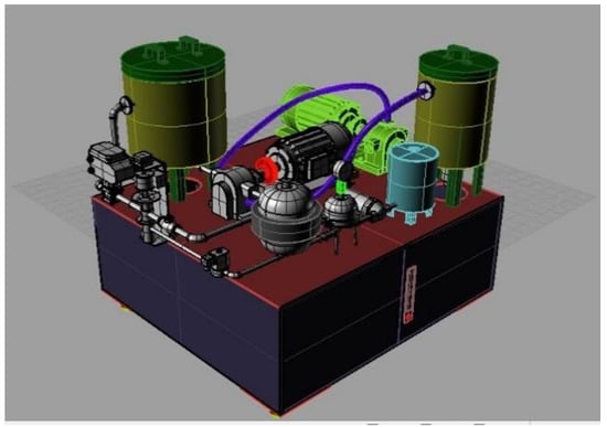
Figure 7.
Asphalt foaming device equipment platform.
3.2. Fault Tree of Asphalt Foaming Device
This section describes how the reliability evaluation method proposed in Section 2 is used to study the asphalt foaming device. This method enables checking the causes of the asphalt foaming device’s failures, thus assisting the decision-makers in preventing and reducing such accidents in the future. Let the asphalt foaming device failure denote the top event. This top event (i.e., asphalt foaming device failure) may be caused by six events: asphalt pipeline system failure, foaming water system failure, compressed air system failure, asphalt heating and heat preservation system failure, foamed asphalt preparation failure, and PLC automatic control device failure. Therefore, the six intermediate events must be associated with the top event through the logic gate. These events are placed in the second row in a parallel relationship. A successive analysis following the rules established by the fault tree describes the top-down study, finally yielding the top event’s root cause. Following this procedure, the asphalt foaming device’s fault tree is established, and the bottommost layer subdivided into 71 events is obtained. Next, the fault tree is qualitatively judged and quantitatively analyzed.
4. Results Analysis and Discussion
4.1. Bottommost Events’ Fuzzy Number Aggregation
The expert group’s weight factors are calculated using Equation (19), and the different opinions are summarized. The aggregation calculation followed Equation (8) with the relaxation factor set to 0.5 to ensure the evaluation objectivity. As an example, Table 1 details the calculations for event X20. These calculations include similarity , average consistency , relative agreement , weight factor, and total weight. A legend (Table 2) is provided for Table 1 to illustrate the meaning of the symbols.

Table 1.
Aggregate calculation table for the asphalt foaming device’s basic event X20.

Table 2.
Description of the symbols in Table 1.
4.2. Top Event’s Aggregate Fuzzy Number
The fuzzy fault tree’s logic gate relations and Boolean algebra, combined with the fuzzy number’s characteristics (see Equations (12)–(14)) and the basic events’ aggregated fuzzy numbers (Table 2), enable obtaining the aggregated fuzzy numbers for the middle events in the asphalt foamed device’s fault tree. Similarly, one can obtain the aggregated fuzzy number of the top event. The defuzzification of the top event’s aggregate fuzzy number and Equation (16) yield the fuzzy possibility score of the asphalt foaming plant fault tree’s top event, which equals . Now, Equation (17) enables calculating the top event’s probability, yielding .
4.3. Fuzzy Importance of the Bottommost Events
Fuzzy importance assessment identifies the bottommost event that significantly affects the top event. Thus, a quantitative evaluation of the bottommost events’ fuzzy importance provides a reference for decision-makers and designers, prioritizing the safety measures’ formulation from the reliability perspective. The fuzzy importance of the asphalt foaming device’s 71 bottommost events is calculated using Equation (18), and the results are shown in Table 3.

Table 3.
The fuzzy importance of the asphalt foaming device’s basic events.
The analysis highlighted several events critical to the asphalt foaming device’s performance, the most prominent being the asphalt pipeline blockage (X9), insufficient electric heating (X43), and foaming cavity deformation (X49). These results agree with the asphalt foaming device’s failure frequency and performance in engineering applications.
4.4. Analysis
At present, there are relatively few statistical data about the failure of asphalt foaming devices from around the world, so there is no other authoritative sample database to compare the calculation results of the model in this paper. However, the calculation results are of the same magnitude as the actual engineering application results of asphalt foaming devices. In conclusion, the results obtained by this model are consistent with the actual situation, which verifies the reliability and validity of the model.
5. Experimental Results and Analysis
5.1. CFD Analysis
In this paper, ANSYS FLUENT version 15 of CFD technology is used to simulate the foaming behavior of asphalt. FLUENT software has rich physical models, advanced numerical calculation methods and powerful post-processing functions, which can well simulate the multiphase flow model and is suitable for the simulation calculation of asphalt foaming behavior.
The asphalt foaming process comprises multiphysical field and multiflow field coupling processes, which involve the theory of direct contact heat transfer, mass transfer, phase transition, turbulence, and so on. Asphalt is a non-Newtonian fluid, water is a typical Newtonian fluid, air is a compressible fluid, and there is a gas–liquid three-phase flow in the preparator. The calculation model chooses the mixed-phase model. The temperature of asphalt is 160 °C and the temperature of water and air is room temperature. Water speed, asphalt speed, and air speed were set. Asphalt viscosity was selected as a single experimental variable with the following instances: 0.2, 0.3, 0.5, and 0.8 Pa·s.
FLUENT has a professional preprocessing software, “Gambit”, which has several functions such as geometric modeling, meshing of the model, and establishment of boundary conditions [49]. In addition, Gambit has super-Boolean operation abilities. However, in the establishment of the 3D solid model (especially for modeling of very complex entities), the use of Gambit software is more tedious and has a high error rate. Thus, it does not provide the easiness and robustness provided by the professional 3D tools, such as UG, Pro/E, and others. In this paper, considering the characteristics of the foaming cavity with multicurved surface and multiple entrances, UG software was used to establish a simplified 3D solid model of the foaming cavity. The resulting “.STP” file was exported and imported into the Gambit software. Gambit’s powerful Boolean computing capabilities and geometric correction functions ensure that a high-quality mesh is drawn for the 3D solid model. This, in turn, provides the appropriate conditions for the subsequent simulation analysis of FLUENT.
Therefore, the asphalt foaming cavity is meshed, as shown in Figure 8, and the boundary conditions are set as shown in Table 4.
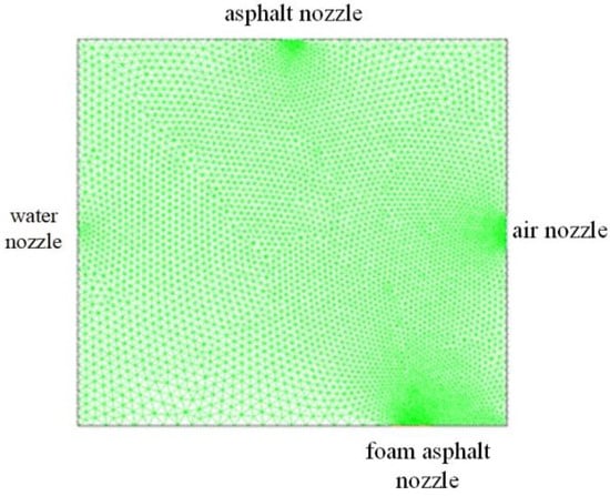
Figure 8.
Meshing.

Table 4.
Boundary conditions.
The three-dimensional solid model of the asphalt foaming cavity can be established based on the corresponding volume and shape, the inlet size of hot asphalt, the outlet size of foamed asphalt, and the outlet position of the foaming cavity (As shown in Figure 9). Because the flow field inside the foaming cavity is independent of the cavity outer wall analyzed by FLUENT software, the foaming cavity can be simplified and the model structure inside the cavity can be created directly. Thus, the established foaming cavity model is actually a region where a variety of physical fields are in contact with each other and are coupled with each other. In this paper, taking the capsule as an example, and considering the actual convenient equipment size, the water nozzle is 0.5 mm; the air nozzle is 4 mm; and the asphalt nozzle and the foam asphalt nozzle are all of a standard size.
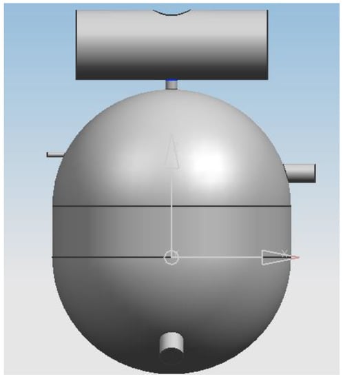
Figure 9.
The three-dimensional solid model of the asphalt foaming cavity.
Moreover, the quality of foaming cavity 3D solid meshing has a crucial impact on the calculation accuracy and robustness of the model in FLUENT. The STP file saved in the previous step is imported into the FLUENT grid tool Gambit. In order to achieve consistent contact between the meshes, the small-volume entities (four nozzle entities) are netted, and finally the foaming cavity is meshed. The grid type is a Tet/Hybrid (mainly a tetrahedral grid, including hexahedral, conical, and wedge-shaped grid units). In addition, the partition type is TGrid to facilitate the division of complex surfaces where geometries of different sizes intersect. In order to realize the relative uniformity of meshing, the meshing of small geometry is divided by local refinement to ensure the calculation accuracy. For geometries with large volumes, a mesh with a large size is used to reduce the computational time. The interval size of the water nozzle is 0.2 mm, the interval size of the asphalt nozzle is 1 mm, the interval size of the air nozzle is 1.2 mm, the interval size of the foamed asphalt outlet is 1.5 mm, and the foaming cavity cell grid interval size is 3 mm. The specific meshing is shown in Figure 10.
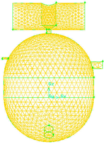
Figure 10.
Meshing of the foaming cavity.
In addition, asphalt foaming is a complex multiphase coupling process of hot asphalt, water, and air in a specific container. The flow field in the foaming chamber has strong fuzziness and coupling. Overall, there are two numerical methods to deal with multiphase flow: (1) the Euler–Lagrange method and (2) the Euler–Euler method. The Lagrangian discrete phase model in FLUENT follows the Euler–Lagrange method, where the discrete phase is obtained by processing the movement of a large number of particles, bubbles, or droplets in the flow field. On the other hand, the Euler–Euler method treats the different phases, which run through each other, as a continuous fluid. In terms of flow models, there are three Euler multiphase flow models in FLUENT: the Volume Of Fluid (VOF) model, the Mixture model, and the Eulerian model.
The mixture model can be used for two-phase flow or multiphase flow (fluid or particle) analysis. In the Euler model, the phases are treated as interconnected continuities. Thus, the mixture model solves the momentum equation of the mixture and describes the discrete phases by their relative velocities. Applications of the mixture model include low-load particle loads, bubble flows, sedimentation, and cyclone separators. The mixture model can also be used for homogeneous multiphase flows without discrete relative velocities.
Asphalt foaming belongs to the mixture of multiphase flow. The mixture model is used to simulate the flow field inside the cavity, which must meet the conservation of mass, momentum and energy. In the mixture multiphase flow model, the effects of sliding velocity should be considered. The continuity equation, energy conservation equation, momentum conservation equation, standard K -ε model equation, algebraic slip equation and volume fraction equation of the second phase were used to solve the model. The cloud images of all physical fields were obtained by FLUENT based on the boundary division and numerical analysis of the asphalt foaming principle.
An iterative calculation approach was employed after the model was developed, and the corresponding parameters were set. As the iterative calculation method attains convergence, cloud images of the pressure field, velocity field, and temperature field were intercepted by the FLUENT software for comparative analysis.
Physical field when asphalt viscosity is 0.2 Pa·s, 0.3 Pa·s, 0.5 Pa·s and 0.8 Pa·s:
- (1)
- Velocity field
It can be noted from the velocity field presented in Figure 11 that the asphalt is in direct contact and coupling with air and water vapor after entering the foaming cavity. In addition, it is shown that the speed of the asphalt drops sharply. The initial speed is relatively high. When the viscosity is 0.2 Pa·s, the speed change is relatively limited after the asphalt enters the foaming cavity. On the other hand, when the asphalt with a viscosity of 0.8 Pa·s enters the foaming cavity, the speed decreases sharply. Based on these results, it is demonstrated that the higher the viscosity of the asphalt, the worse its fluidity is, which is not conducive to the coupling of the flow field. This reduces the stability of the asphalt foaming recycling technology.
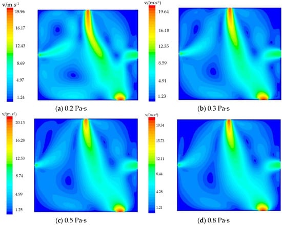
Figure 11.
Velocity field of asphalt with different viscosities.
- (2)
- Temperature field
As can be seen from the temperature field of asphalt with different viscosities in Figure 12, when the asphalt viscosity is 0.2 Pa·s, the track of high-temperature asphalt is relatively long, and the atomized water vapor is accompanied by slight reflux. As the viscosity of the asphalt increases, the asphalt’s high-temperature trajectory becomes shorter and the atomized water vapor reflux is weakened. In addition, the reflux is generally eliminated when the asphalt viscosity is greater than 0.5 Pa·s. This phenomenon appeared because at the entrances of the same size, temperature and speed increase the viscosity of asphalt, which is translated to an increase in the energy of asphalt into the foam chamber. The greater the energy of the liquid water evaporated into water vapor, the easier it is for the foaming cavity pressure to increase, leading to the water droplets being atomized rapidly to 100~150 microns, and ensuring that the phase change rate of water and steam rises quickly and efficiently. Overall, the coupling between asphalt and atomized water vapor is beneficial to the preparation of foamed asphalt.
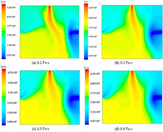
Figure 12.
Temperature field of asphalt with different viscosities.
- (3)
- Pressure field
Figure 13 highlights the pressure field of asphalt with different viscosities. The results show that there are obvious differences in pressure diagrams of asphalt with different viscosity levels. When the viscosity is 0.2 Pa·s, the overall pressure of the foam cavity is low, but the local pressure is high, and the pressure viscosity is obvious. When the viscosity is increased to 0.3 Pa·s, the overall pressure increases slightly, and individual temperature viscosity is reduced. Moreover, in the case of a viscosity of 0.5 Pa·s, the overall pressure distribution is uniform, and the phenomenon of pressure viscosity is generally eliminated. When the viscosity of asphalt is increased to 0.8 Pa·s, the overall resulting pressure is higher compared to the previous scenarios, and multiple local high-pressure positions appear again. Overall, when the asphalt viscosity is about 0.5 Pa·s, the pressure distribution is uniform and there is no local high pressure. Thus, the environment in the foam chamber is relatively stable, and the asphalt foam liquid film is often not easy to destroy. Currently, the stability of asphalt foaming recycling technology is considered to be the highest.
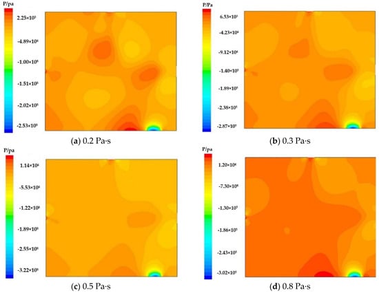
Figure 13.
Pressure field of asphalt with different viscosities.
5.2. Comparative Analysis with Experimental Data
The expansion rate and half-life data of used asphalt from Hohhot, China, were tested under the condition of adding 1% and 2% water (see Table 5). A contrast diagram of the asphalt foaming process can be seen in Figure 14.

Table 5.
Data comparison of different viscosities of the same asphalt in the experiment.
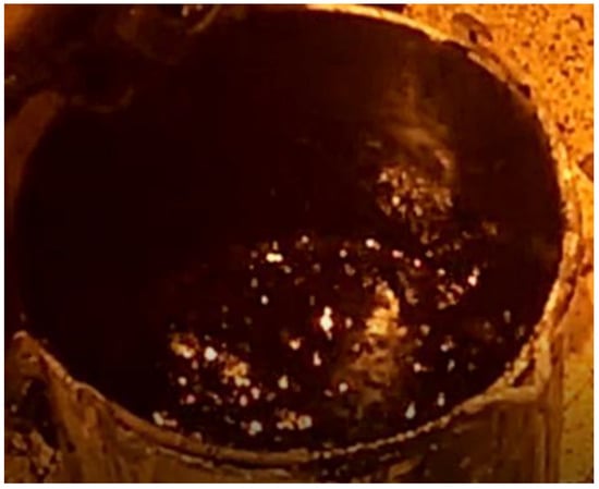
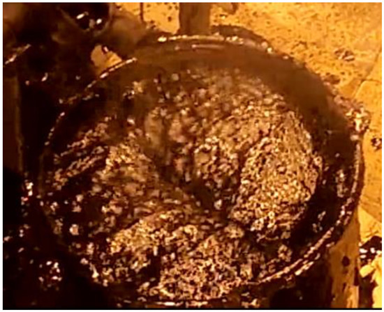
Figure 14.
Comparison diagram of asphalt foaming process.
6. Conclusions
The fault data on the bottommost events in the asphalt foaming device’s fault tree are scarce and uncertain. Thus, this work proposes a fuzzy FTA method based on the intuitionistic fuzzy set and the Delphi method. First, the asphalt foaming device fault tree was developed. The tree was fuzzified, and the bottommost events were judged by a group of experts. The Delphi method was utilized to determine the experts’ weights. Next, the experts’ opinions were aggregated, and the fuzzy numbers for each bottommost event were obtained. These results enabled calculating the top event’s fuzzy number, which was then transformed into the fuzzy possibility score. Furthermore, the top event’s probability was calculated as well as the fuzzy significance for 71 distinct bottommost events. The obtained asphalt foaming device’s failure probability was found to be 7.512 × 10⁻². Among the 71 bottommost events, asphalt pipeline blockage, insufficient electric heating, and foaming cavity deformation were highlighted as the events with the highest fuzzy importance for the asphalt foaming device. These results are in line with the asphalt foaming device’s fault performance and frequency in the engineering applications. At present, there are relatively few statistical data about the failure of asphalt foaming devices in the world, so there is no other authoritative sample database to compare the calculation results of the model in this paper. However, the calculation results are of the same magnitude as the actual engineering application results of the asphalt foaming device. In conclusion, the results obtained by the model were found to be consistent with the experimental actual data, verifying the reliability and validity of the model. The successful implementation of the proposed method provides new opportunities for the reliability evaluation of asphalt foaming recycling technology.
A theoretical analysis was carried out on the asphalt foaming mechanism, combined with engineering experience, in order to find the most suitable range of foamed asphalt viscosity for the production of high-quality foamed asphalt. Employing the developed model, the asphalt foaming process was simulated, employing a CFD analysis method. In addition, numerical simulations were conducted to assess the impact of different asphalt viscosities, and the simulations were compared and verified using experimental results. Finally, the optimal foamed asphalt viscosity range for the production of high-quality foamed asphalt was determined. By comparing the numerical values of the expansion rate and half-life with the experimental data, it is concluded that the lower the viscosity of asphalt, the better its fluidity and the easier it is to be coupled with water and air. The heat embedded in high-viscosity hot asphalt is beneficial to the vaporization of water, which provides the necessary conditions for asphalt foaming. When the asphalt viscosity is very large, the pressure distribution in the foaming cavity is uneven and there is a local high pressure. On the other hand, when the asphalt viscosity is about 0.5 Pa·s, the pressure distribution in the foaming cavity is more uniform and suitable for asphalt foaming. The heat contained in high-viscosity hot asphalt is mostly in contact with water, which is useful for the vaporization of water. This will provide the necessary conditions for asphalt foaming. When the asphalt viscosity is about 0.5 Pa·s, the pressure distribution in the foaming cavity is relatively uniform, which is suitable for asphalt foaming. Based on the reasons mentioned above, it is concluded that an asphalt viscosity in the range of 0.3–0.5 Pa·s provides the optimal conditions to improve the stability of asphalt foaming recycling technology.
Author Contributions
Conceptualization and methodology, H.C. and Z.L.; software, H.C. and Z.L.; validation, H.C., Z.L. and N.S.; formal analysis, H.C. and N.S.; investigation, H.C., Z.L. and N.S.; resources, H.C.; data curation, H.C.; writing—original draft preparation, H.C. and Z.L.; writing—review and editing, H.C. and N.S.; visualization, Z.L. and N.S.; supervision, N.S.; project administration, H.C.; funding acquisition, H.C. All authors have read and agreed to the published version of the manuscript.
Funding
This research was funded in part by the National Natural Science Foundation of China, under Grant 52065051 and Grant 51265033 and the International Cooperation and Exchange projects under Grant 52011530029.
Institutional Review Board Statement
Not applicable.
Informed Consent Statement
Not applicable.
Data Availability Statement
Data sharing is not applicable.
Conflicts of Interest
The authors declare no conflict of interest.
References
- Ramanujam, J.M.; Jones, J.D. Characterization of foamed-bitumen stabilisation. Int. J. Pavement Eng. 2007, 8, 111–122. [Google Scholar] [CrossRef]
- Kattan, H.M.; Mahmoud, I.A.; Baig, M.G.; Wahhab, H.I.A.A. Study of road bases construction in Saudi Arabia using foam asphalt. Constr. Build. Mater. 2012, 26, 113–121. [Google Scholar]
- Cheng, H.Y.; Hao, H.; Zhao, N.; Zhai, Z.P. Sectional lumped parameter model using bond graph and simulation for hot asphalt pipelines. J. Chin. Inst. Eng. 2019, 42, 573–582. [Google Scholar] [CrossRef]
- Wang, T.; Si, J.; Yin, L.; Li, N.; Li, J.; Dong, F.; Yu, X. Influence of base asphalt aging levels on the foaming characteristics and rheological properties of foamed asphalt. Constr. Build. Mater. 2018, 177, 43–50. [Google Scholar]
- Skotnicki, L.; Kuzniewski, J.; Szydlo, A. Stiffness Identification of Foamed Asphalt Mixtures with Cement, Evaluated in Laboratory and In Situ in Road Pavements. Materials 2020, 13, 1128. [Google Scholar] [CrossRef] [PubMed] [Green Version]
- Bairgi, B.K.; Mannan, U.A.; Tarefder, R.A. Influence of foaming on tribological and rheological characteristics of foamed asphalt. Constr. Build. Mater. 2019, 205, 186–195. [Google Scholar] [CrossRef]
- Wang, A.L.; Cheng, H.Y.; Wang, J.W. Theoretical Evaluation on Expansion Ratio and Half-time of Foamed Asphalt. J. Build. Mater. 2009, 12, 684–688. [Google Scholar]
- Ryan, J.; Braham, A. The characterisation of foamed asphalt cement using a rotational viscometer. Int. J. Pavement Eng. 2017, 18, 744–752. [Google Scholar] [CrossRef]
- Yin, F.; Arambula-Mercado, E.; Newcomb, D. Effect of laboratory foamer on asphalt foaming characteristics and foamed mixture properties. Int. J. Pavement Eng. 2017, 18, 358–366. [Google Scholar] [CrossRef]
- Hailesilassie, B.W.; Hugener, M.; Partl, M.N. Influence of foaming water content on foam asphalt mixtures. Constr. Build. Mater. 2015, 85, 65–77. [Google Scholar] [CrossRef]
- Liu, S.J.; Zhou, S.B.; Peng, A.H. Analysis of moisture susceptibility of foamed warm mix asphalt based on cohesion, adhesion, bond strength, and morphology. J. Clean Prod. 2020, 277, 12. [Google Scholar] [CrossRef]
- Wang, A.L.; Cheng, H.Y.; Wang, J.W. Research on Foamed Asphalt Technology and Equipment. In Proceedings of the 2009 International Conference on Energy and Environment Technology, Guilin, China, 16–18 October 2009; pp. 287–291. [Google Scholar]
- Li, K.; Jiao, S. Optimization of process parameters for preparation of different foamed asphalts using cold recycling equipment. J. Chang. Univ. Nat. Sci. Ed. 2014, 34, 13–17. [Google Scholar]
- Hsu, P.Y.; Aurisicchio, M.; Angeloudis, P.; Whyte, J. Understanding and visualizing schedule deviations in construction projects using fault tree analysis. Eng. Constr. Archit. Manag. 2020, 27, 2501–2522. [Google Scholar] [CrossRef]
- Wang, F.C.; Zheng, P.M.; Dai, J.L.; Wang, H.; Wang, R.Q. Fault tree analysis of the causes of urban smog events associated with vehicle exhaust emissions: A case study in Jinan, China. Sci. Total Environ. 2019, 668, 245–253. [Google Scholar] [CrossRef]
- Peeters, J.F.W.; Basten, R.J.I.; Tinga, T. Improving failure analysis efficiency by combining FTA and FMEA in a recursive manner. Reliab. Eng. Syst. Saf. 2018, 172, 36–44. [Google Scholar] [CrossRef] [Green Version]
- Salma, V.; Friedl, F.; Schmehl, R. Improving reliability and safety of airborne wind energy systems. Wind Energy 2020, 23, 340–356. [Google Scholar] [CrossRef] [Green Version]
- Kabir, S. An overview of fault tree analysis and its application in model based dependability analysis. Expert Syst. Appl. 2017, 77, 114–135. [Google Scholar] [CrossRef] [Green Version]
- Wang, Y.G.; Duan, X.D.; Liu, X.D.; Wang, C.R.; Li, Z.D. A spectral clustering method with semantic interpretation based on axiomatic fuzzy set theory. Appl. Soft. Comput. 2018, 64, 59–74. [Google Scholar] [CrossRef]
- Tanaka, H.; Fan, L.T.; Lai, F.S.; Toguchi, K. Fault-tree analysis by fuzzy probability. IEEE Trans. Reliab. 1983, 32, 453–457. [Google Scholar] [CrossRef]
- Onisawa, T. Fuzzy theory in reliability-analysis. Fuzzy Sets Syst. 1989, 30, 361–363. [Google Scholar] [CrossRef]
- Misra, K.B.; Weber, G.G. A new method for fuzzy fault tree analysis. Microelectron. Reliab. 1989, 29, 195–216. [Google Scholar] [CrossRef]
- Singer, D. A fuzzy set approach to fault tree and reliability analysis. Fuzzy Sets Syst. 1990, 34, 145–155. [Google Scholar] [CrossRef]
- Kabir, S.; Walker, M.; Papadopoulos, Y.; Rüde, E.; Securius, P. Fuzzy temporal fault tree analysis of dynamic systems. Int. J. Approx. Reason. 2016, 77, 20–27. [Google Scholar] [CrossRef] [Green Version]
- Kabir, S.; Geok, T.K.; Kumar, M.; Yazdi, M.; Hossain, F. A Method for Temporal Fault Tree Analysis Using Intuitionistic Fuzzy Set and Expert Elicitation. IEEE Access 2020, 8, 980–996. [Google Scholar] [CrossRef]
- Kumar, M.; Sharma, S. The alpha, beta-Cut Intervals and Weakest t-Norm Based Importance Measure for Criticality Analysis in Intuitionisitic Fuzzy Fault Tree Analysis of LNG-ESD System. Int. J. Uncertain. Fuzziness Knowl. Based Syst. 2021, 29, 119–143. [Google Scholar] [CrossRef]
- Lin, S.; Jia, L.M.; Wang, Y.H. Safety Assessment of Complex Electromechanical Systems Based on Hesitant Interval-Valued Intuitionistic Fuzzy Theory. Int. J. Fuzzy Syst. 2019, 21, 2405–2420. [Google Scholar] [CrossRef]
- Zarei, E.; Yazdi, M.; Abbassi, R.; Khan, F. A hybrid model for human factor analysis in process accidents: FBN-HFACS. J. Loss Prev. Process Ind. 2019, 57, 142–155. [Google Scholar] [CrossRef]
- Yazdi, M. Footprint of knowledge acquisition improvement in failure diagnosis analysis. Qual. Reliab. Eng. Int. 2019, 35, 405–422. [Google Scholar] [CrossRef]
- Hermansyah, H.; Kumaraningrum, A.R.; Purba, J.H.; Edison; Yohda, M. Safety Analysis Technique for System with Limited Data: Case Study of the Multipurpose Research Reactor in Indonesia. Energies 2020, 13, 29. [Google Scholar] [CrossRef] [Green Version]
- Liu, Z.; Song, W.; Cui, B.; Wang, X.; Yu, H. A Comprehensive Evaluation Model for Curtain Grouting Efficiency Assessment Based on Prospect Theory and Interval-Valued Intuitionistic Fuzzy Sets Extended by Improved D Numbers. Energies 2019, 12, 3674. [Google Scholar] [CrossRef] [Green Version]
- Qiao, W.; Liu, Y.; Ma, X.; Liu, Y. Human Factors Analysis for Maritime Accidents Based on a Dynamic Fuzzy Bayesian Network. Risk Anal. 2020, 40, 957–980. [Google Scholar] [CrossRef] [PubMed]
- Zhang, P.; Qin, G.J.; Wang, Y.H. Risk Assessment System for Oil and Gas Pipelines Laid in One Ditch Based on Quantitative Risk Analysis. Energies 2019, 12, 21. [Google Scholar] [CrossRef] [Green Version]
- Li, C.; Jiang, Y.; Chen, B. Fuzzy Fault Tree Analysis of the Cycloid Enveloping Reducer. J. Northeast. Univ. Nat. Sci. 2017, 38, 706–710 + 715. [Google Scholar]
- Meng, X.; Ma, Y.; Sun, J. Vehicle Accidents Bow-tie Model on Urban Arterial Road. J. Transp. Syst. Eng. Inf. Technol. 2020, 20, 178–186. [Google Scholar]
- Huang, S.J.; Duan, R.X.; He, J.J.; Feng, T.; Zeng, Y.N. Fault Diagnosis Strategy for Complex Systems Based on Multi-Source Heterogeneous Information Under Epistemic Uncertainty. IEEE Access 2020, 8, 50921–50933. [Google Scholar] [CrossRef]
- Wan, S.-P.; Lin, L.-L.; Dong, J.-Y. MAGDM based on triangular Atanassov’s intuitionistic fuzzy information aggregation. Neural Comput. Appl. 2017, 28, 2687–2702. [Google Scholar] [CrossRef]
- Lin, S.; Wang, Y.; Jia, L.; Zhang, H. Reliability assessment of complex electromechanical systems: A network perspective. Qual. Reliab. Eng. Int. 2018, 34, 772–790. [Google Scholar] [CrossRef]
- Kumar, M. An Area IF-Defuzzification Technique and Intuitionistic Fuzzy Reliability Assessment of Nuclear Basic Events of Fault Tree Analysis. In Harmony Search and Nature Inspired Optimization Algorithms; Yadav, N., Yadav, A., Bansal, J.C., Deep, K., Kim, J.H., Eds.; Springer: Singapore, 2019; Volume 741, pp. 845–856. [Google Scholar]
- Singh, S.K.; Yadav, S.P. Intuitionistic fuzzy multi-objective linear programming problem with various membership functions. Ann. Oper. Res. 2018, 269, 693–707. [Google Scholar] [CrossRef]
- Cheliyan, A.S.; Bhattacharyya, S.K. Fuzzy fault tree analysis of oil and gas leakage in subsea production systems. J. Ocean Eng. Sci. 2018, 3, 38–48. [Google Scholar] [CrossRef]
- Sen, S.; Roesler, J.; Ruddell, B.; Middel, A. Cool Pavement Strategies for Urban Heat Island Mitigation in Suburban Phoenix, Arizona. Sustainability 2019, 11, 4452. [Google Scholar] [CrossRef] [Green Version]
- Ballesteros-Coll, A.; Portal-Porras, K.; Fernandez-Gamiz, U.; Zulueta, E.; Lopez-Guede, J.M. Rotating Microtab Implementation on a DU91W250 Airfoil Based on the Cell-Set Model. Sustainability 2021, 13, 9114. [Google Scholar] [CrossRef]
- Zhou, G.; Zhang, Q.; Bai, R.N.; Fan, T.; Wang, G. The diffusion behavior law of respirable dust at fully mechanized caving face in coal mine: CFD numerical simulation and engineering application. Process Saf. Environ. Prot. 2017, 106, 117–128. [Google Scholar] [CrossRef]
- Al-quraishi, M.; Sarip, S.; Kaidi, H.M.; Ardila-Rey, J.A.; Muhammad-Sukki, F. A CFD Analysis for Novel Close-Ended Deflector for Vertical Water Turbines. Sustainability 2022, 14, 2790. [Google Scholar] [CrossRef]
- McPherson, S.; Reese, C.; Wendler, M.C. Methodology Update: Delphi Studies. Nurs. Res. 2018, 67, 404–410. [Google Scholar] [CrossRef] [PubMed]
- Zhao, H.; Li, N. Optimal Siting of Charging Stations for Electric Vehicles Based on Fuzzy Delphi and Hybrid Multi-Criteria Decision Making Approaches from an Extended Sustainability Perspective. Energies 2016, 9, 270. [Google Scholar] [CrossRef] [Green Version]
- De Liano, B.G.G.; Pascual-Ezama, D. The Delphi Method as a technique to study Validity of Content. An. Psicol. 2012, 28, 1011–1020. [Google Scholar]
- Wen, Z. FLUENT Fluid Computing Application Tutorial, 2nd ed.; Tsinghua University Press: Beijing, China, 2013; pp. 17–36. [Google Scholar]
Publisher’s Note: MDPI stays neutral with regard to jurisdictional claims in published maps and institutional affiliations. |
© 2022 by the authors. Licensee MDPI, Basel, Switzerland. This article is an open access article distributed under the terms and conditions of the Creative Commons Attribution (CC BY) license (https://creativecommons.org/licenses/by/4.0/).