Article

Multi-Objective Optimization of CNC Turning Process Parameters Considering Transient-Steady State Energy Consumption

1
Department of Industrial Engineering, Shandong University of Science and Technology, Qingdao 266590, China
2
Institute of Smart Manufacturing Systems, School of Construction Machinery, Chang’an University, Xi’an 710064, China
3
College of Engineering and Technology, Southwest University, Chongqing 400715, China
4
School of Mechanical and Electrical Engineering, Henan University of Technology, Zhengzhou 450001, China
5
School of Mechanical and Electrical Engineering, Qingdao University, Qingdao 266071, China
*
Authors to whom correspondence should be addressed.
Sustainability 2021, 13(24), 13803; https://doi.org/10.3390/su132413803
Submission received: 3 November 2021 / Revised: 9 December 2021 / Accepted: 10 December 2021 / Published: 14 December 2021
(This article belongs to the Special Issue Advanced Clean Energy Systems)

Abstract

:
Energy-saving and emission reduction are recognized as the primary measure to tackle the problems associated with climate change, which is one of the major challenges for humanity for the forthcoming decades. Energy modeling and process parameters optimization of machining are effective and powerful ways to realize energy saving in the manufacturing industry. In order to realize high quality and low energy consumption machining of computer numerical control (CNC) lathe, a multi-objective optimization of CNC turning process parameters considering transient-steady state energy consumption is proposed. By analyzing the energy consumption characteristics in the process of machining and introducing practical constraints, such as machine tool equipment performance and tool life, a multi-objective optimization model with turning process parameters as optimization variables and high quality and low energy consumption as optimization objectives is established. The model is solved by non-dominated sorting genetic algorithm-II (NSGA-II), and the pareto optimal solution set of the model is obtained. Finally, the machining process of shaft parts is studied by CK6153i CNC lathe. The results show that 38.3% energy consumption is saved, and the surface roughness of workpiece is reduced by 47.0%, which verifies the effectiveness of the optimization method.

1. Introduction

As the main equipment of (computer numerical control) CNC machining, the CNC machine tool is widely used in various fields of manufacturing. It has complex energy consumption characteristics, high energy consumption, low energy efficiency, and huge potential for energy saving and emission reduction [1,2]. Therefore, domestic and foreign scholars are increasingly active in the research on energy consumption modeling and energy-saving and emission reduction methods of CNC machine tools [3,4,5,6]. In the process of CNC machining, the reasonable selection of process parameters not only affects the indexes of machining cost [7], quality [8] and efficiency [9], but also is closely related to the energy consumption of machine tools [10]. How to optimize the process parameters in the machining process of CNC machine tools is an urgent basic scientific problem to be solved under the background of green manufacturing [11].
Traditional research on process parameters optimization mainly aims at optimizing the quality, cost and efficiency of the process. For example, Zhou et al. [12] took the minimum surface roughness value as an optimization objective, Addona et al. [13] took the comprehensive optimization of processing cost, quality and time as an optimization objective, and Pan et al. [14] took the reliability of milling accuracy as an optimization objective. In recent years, with the increasing severity of energy consumption and environmental problems in manufacturing industry, research considering the objectives of green and low carbon optimization has gradually appeared [15,16]. The existing optimization methods of CNC machining process parameters can be roughly divided into three categories: optimization based on experiment, optimization based on optimization algorithm and optimization based on expert knowledge system [17].
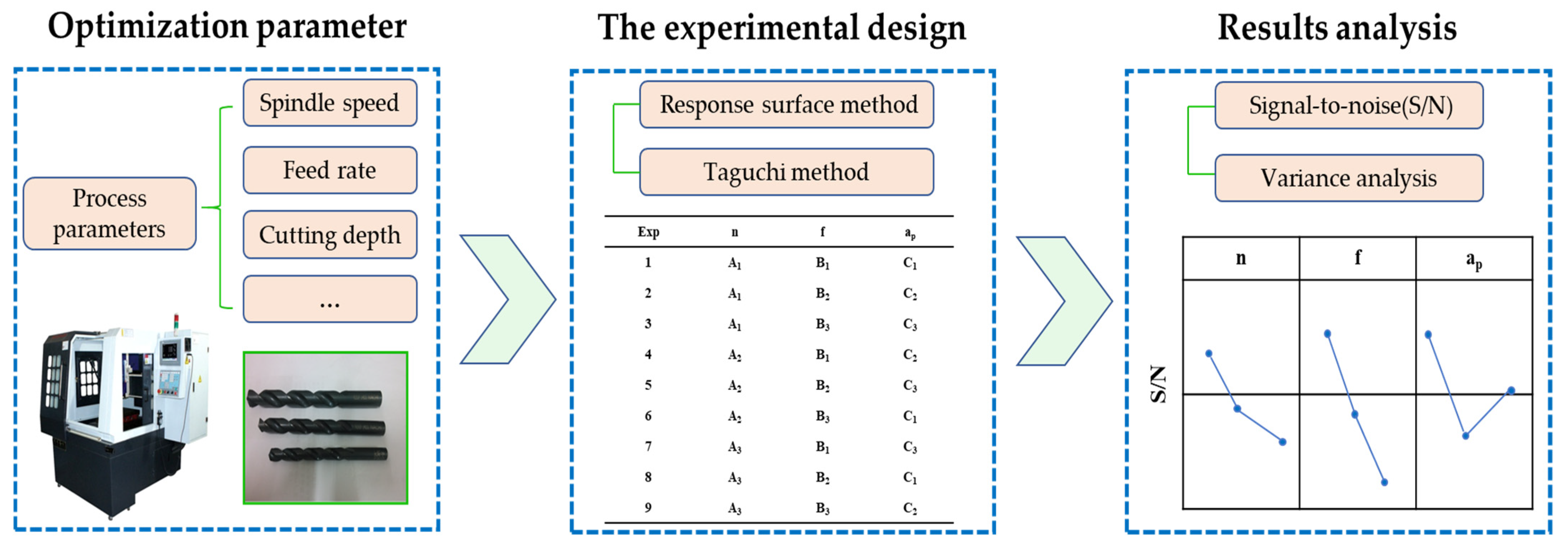
(1) Optimization method based on experiment. Many scholars use the Taguchi method [18] and response surface method [19] to analyze the impact of cutting parameters on energy consumption, efficiency and quality, as shown in Figure 1. For example, Yang et al. [20] studied the influence of CNC milling process parameters on the processing quality under dry cutting by means of experimental design. The Taguchi method was used to design experiments and fit the correlation model between process parameters and quality. The research pointed out that the feed rate has the greatest influence on the processing quality. Sukumar et al. [21] took roughness in CNC milling process as an optimization objective and solved different optimal combination of processing parameters by the Taguchi method and artificial neural network method; the optimization results showed that the optimization strength of the two optimization methods was almost the same. Li et al. [22] put forward an energy efficiency optimization method for CNC milling process parameters based on the Taguchi method and response surface method to study the complex mechanism of coupling energy efficiency and process parameters of machine tools. Liu et al. [23] optimized the high-speed milling process parameters by means of the orthogonal test. The research pointed out that the speed of the spindle should be properly increased, and the roughness of the workpiece surface can be reduced by reducing the feed speed and the feed per tooth. The above experimental-based optimization method is simple and feasible, avoiding the complicated mathematical modeling of energy consumption, and the influence rule of each parameter on the objective function can be analyzed by fewer tests.
(2) Optimization method based on optimization algorithm. For example, Wang et al. [24] took energy consumption, cost and quality of processing as optimization objectives and solved the optimal combination of cutting parameters by the NSGA-II algorithm. The research shows that optimization of cutting parameters is beneficial to energy saving in the process of machining but increases costs. Yan et al. [25] used cutting energy consumption, machining efficiency and surface quality as optimization models of milling process parameters and carried out optimization by gray correlation analysis and the surface response method. Li et al. [26,27] carried out energy efficiency optimization for multi-step CNC planar milling process parameters, established target functions, such as energy efficiency and processing cost, and solved the multi-objective optimization model by applying the multi-objective particle swarm algorithm based on adaptive grid and continuous taboo algorithm, and obtained the optimal configuration of cutting parameters and work steps. Most of the above research on the energy optimization model of the CNC machine tool consider the steady state process energy consumption but ignore the phenomenon of frequent transient process energy consumption and high-power peak in the machining process and lack the consideration of transient process energy consumption. Therefore, to accurately reflect the actual energy consumption and running time of CNC machine tools and guide energy saving of CNC machine tools, a transient-steady state energy consumption function model is established.
(3) Optimization method based on expert knowledge system. For example, the expert knowledge system designed by Arezoo is used to determine the cutting tool and cutting parameters (feed rate, cutting speed, cutting depth, etc.) in the cutting process to establish the expert knowledge base, and to establish the reasoning mechanism based on the expert experience so that the system finally outputs the optimal parameters by gradually adjusting the parameters [28]. Zhou et al. [29] developed a turning expert system with a self-learning function. The system uses the concentrated mathematical model derived from cutting experiments to store the cutting data and uses the self-learning function to modify the cutting mathematical model. It can recommend reasonable and optimized cutting parameters, such as tool, cutting speed and tool life, and predict the machining quality and metal removal rate. The optimization method based on an expert knowledge system depends on the knowledge level and experience of experts, and the optimization results are practical.
In the manufacturing industry, in addition to optimizing process parameters, there are many other methods to achieve energy saving and emission reduction. Liu et al. [30] focused on the classical job shop environment and proposed that energy saving can be achieved by turning off the machines when they lay idle for a comparatively long period. Ma et al. [31] studied how to reduce the energy consumption of holes machining through optimizing the tool path and cutting parameters simultaneously; the integrated optimization methodology can further reduce the energy consumption, compared with optimizing the tool path or cutting parameters separately. Petrovic et al. [32] carried out a series of research on the optimization of machining process route and achieved rich research results.
In view of this, this paper comprehensively considers the traditional optimization objectives and low-carbon optimization objectives to study the machining of shaft parts. Firstly, the energy consumption composition characteristics of the CNC lathe machining process are analyzed, the transient process energy consumption is introduced into the energy consumption model of a CNC lathe, and the transient-steady state energy consumption model of a CNC lathe is constructed, which further improves the accuracy of the model. Secondly, a multi-objective optimization model is established, which takes the spindle speed, feed rate and cutting depth as the optimization variables, and the high quality and low energy consumption machining of the CNC machine tool as the optimization objective. Then, considering the actual constraints, the model is optimized by a non-dominated sorting genetic algorithm with an elite strategy. Finally, the effectiveness and practicability of the optimization method are verified by a case study.

2. Energy Consumption Characteristics Analysis and Energy Consumption Modeling

The energy consumption characteristics of a CNC lathe are more complex than that of common machine tools. In this section, firstly, the energy consumption characteristics of CNC turning are analyzed in detail through actual machining cases. Secondly, the energy consumption of transient process is introduced into the energy consumption model of a CNC lathe, and a comprehensive energy consumption model of transient steady state, which is more consistent with the actual situation and has higher accuracy of the energy consumption prediction, is established.

2.1. Analysis of Energy Consumption Characteristics in CNC Turning Process

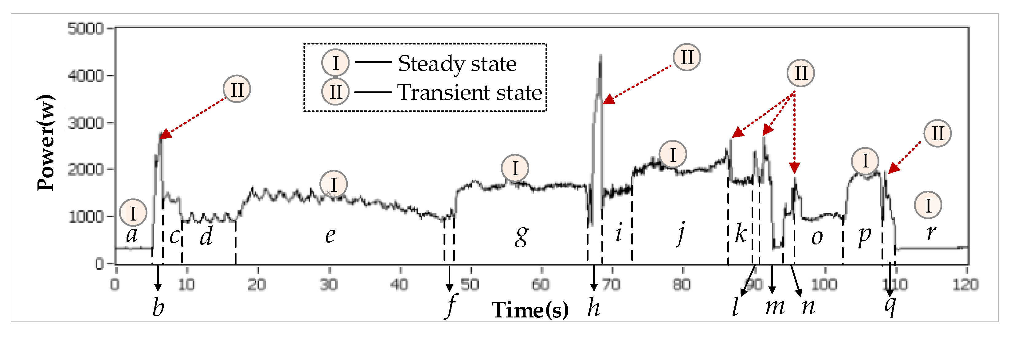
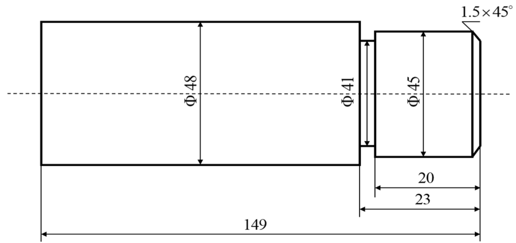
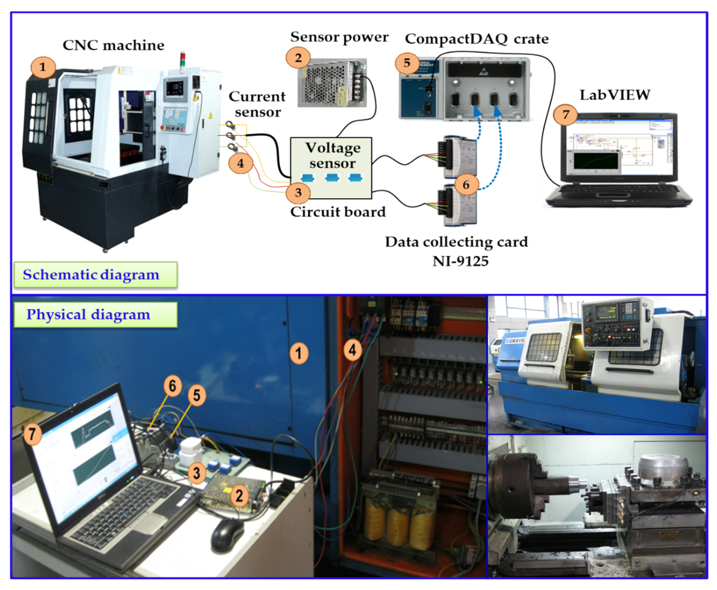
Taking the machining of shaft parts by the ck6153i CNC lathe as an example [33], the basic principle and energy consumption characteristics of CNC machining are analyzed. The machining process of this part mainly includes (a) standby; (b) spindle speedup to 500 r/min; (c) rapid positioning; (d) feeding; (e) end-face turning; (f) rapid positioning and feeding; (g) rough turning; (h) rapid positioning and spindle speedup to 1000 r/min; (i) feeding; (j) finish turning; (k) rapid positioning and feeding; (l) chamfer turning; (m) rapid positioning and spindle speed to 500 r/min; (n) tool changing; (o) rapid positioning and feeding; (p) grooving; (q) rapid positioning to origin; and (r) standby, machining finished. The power curve is shown in Figure 2.
According to Figure 2, the power of the basic module to maintain the standby operation of the machine tool is stable until the spindle of the machine tool accelerates, mainly including the operation of CNC systems, fans and other devices of the CNC machine tool to maintain the basic movement of the machine tool. The spindle starts and accelerates to the corresponding processing parameters. The duration of this process is short, but the peak value is large as shown in the power diagram. This process is called spindle acceleration. After the acceleration of the spindle, the processing activities are carried out at a constant speed. This power is the spindle rotating power, which is a stable value. The tool then moves quickly into the given position to the safe cutting position for a short duration. When positioned in a safe position, the tool approaches the workpiece at a constant feed speed in preparation for cutting. During the process of end-face turning, the power curve of the process changes smoothly without an instantaneous peak value due to the gradual change of the cutting depth and cutting speed. After the end-face turning, the tool rapid feed is positioned to the origin. This process also lasts a short time, but there is an obvious power peak.
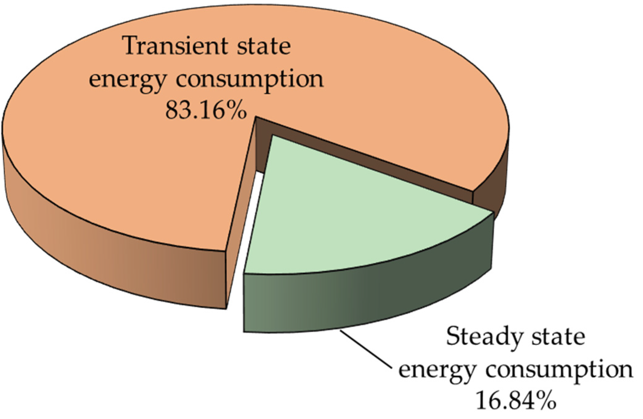
According to the above-mentioned shaft parts machining process, the energy consumption of the CNC machine tool machining processes can be decomposed into two parts: (A) energy consumption of the steady state, such as standby operating, spindle rotating, feeding, material cutting, etc.; (B) energy consumption of transient state, such as spindle speedup, rapid positioning, etc. The transient state is the transition process between the two steady states, which may lead to peak power. Transient states frequently occur during a machining process and their energy consumptions should not be ignored.
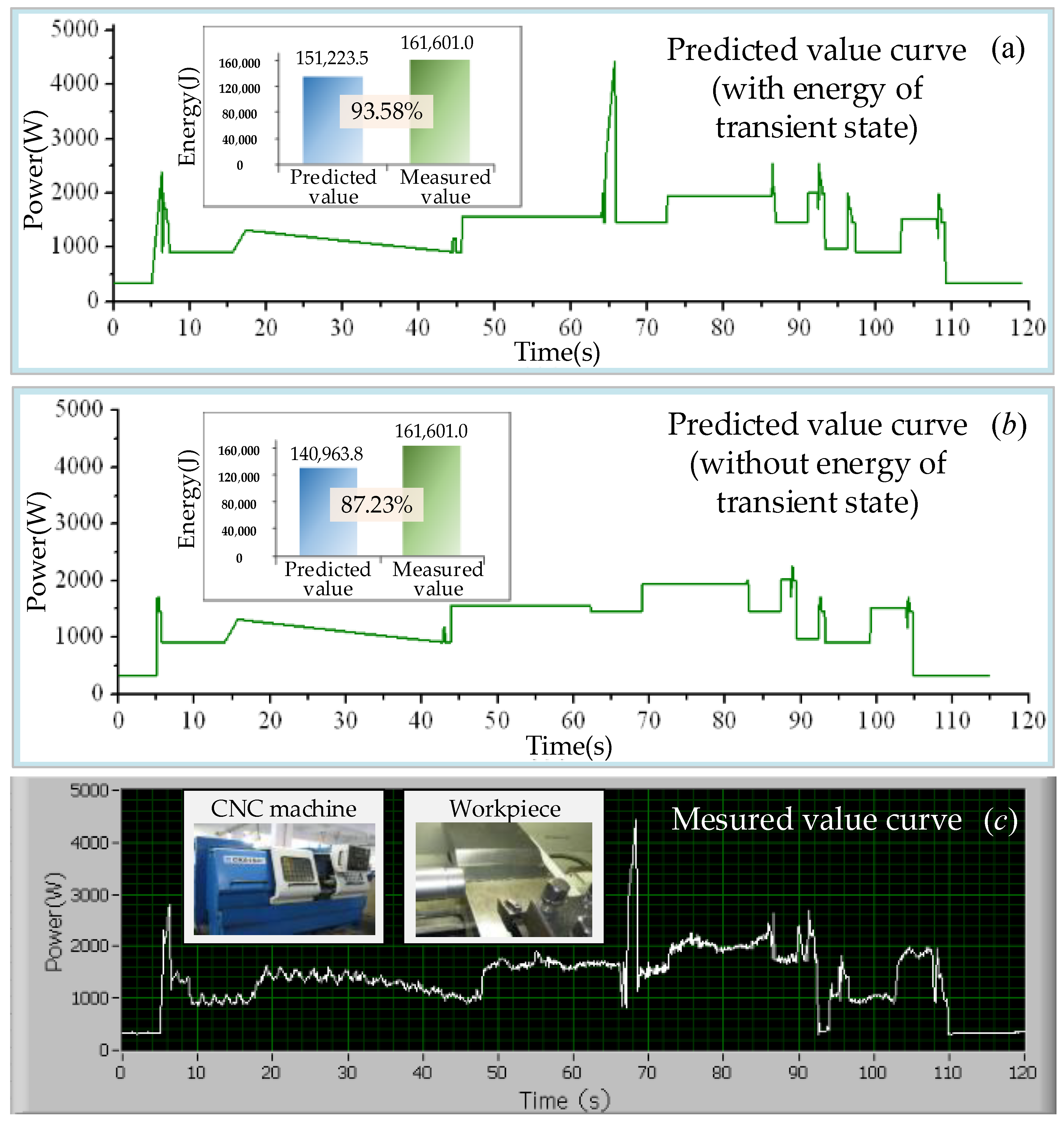
Among the existing research on energy consumption of CNC machine tools, the modeling and optimization of energy consumption in the steady state process during CNC machine tool machining are more in depth, but the research on the transient process is relatively little, and the change in power consumption caused by this process is not paid attention to. For example, the power consumption of transient process is not considered in the method given by He’s research, which results in the calculated value being 9.3% smaller than the measured value [34]. Therefore, it is very important to consider the energy consumption of the transient process in the study of energy consumption optimization of CNC machine tools. As can be seen in Ref. [35], when forecasting the demand for energy consumption of the whole machining process, the predicted value, taking into account the energy consumption of the transient process, is 6.35% higher than the previously predicted value.

2.2. Energy Consumption Modeling of CNC Turning

Based on the analysis of the energy consumption composition characteristics of CNC lathe machining process in the previous section, the CNC lathe machining process is divided into the steady state process and transient state process, and then the CNC lathe machining process energy consumption is divided into steady state process energy consumption and transient state process energy consumption.

2.2.1. Steady State Process Energy Consumption Model

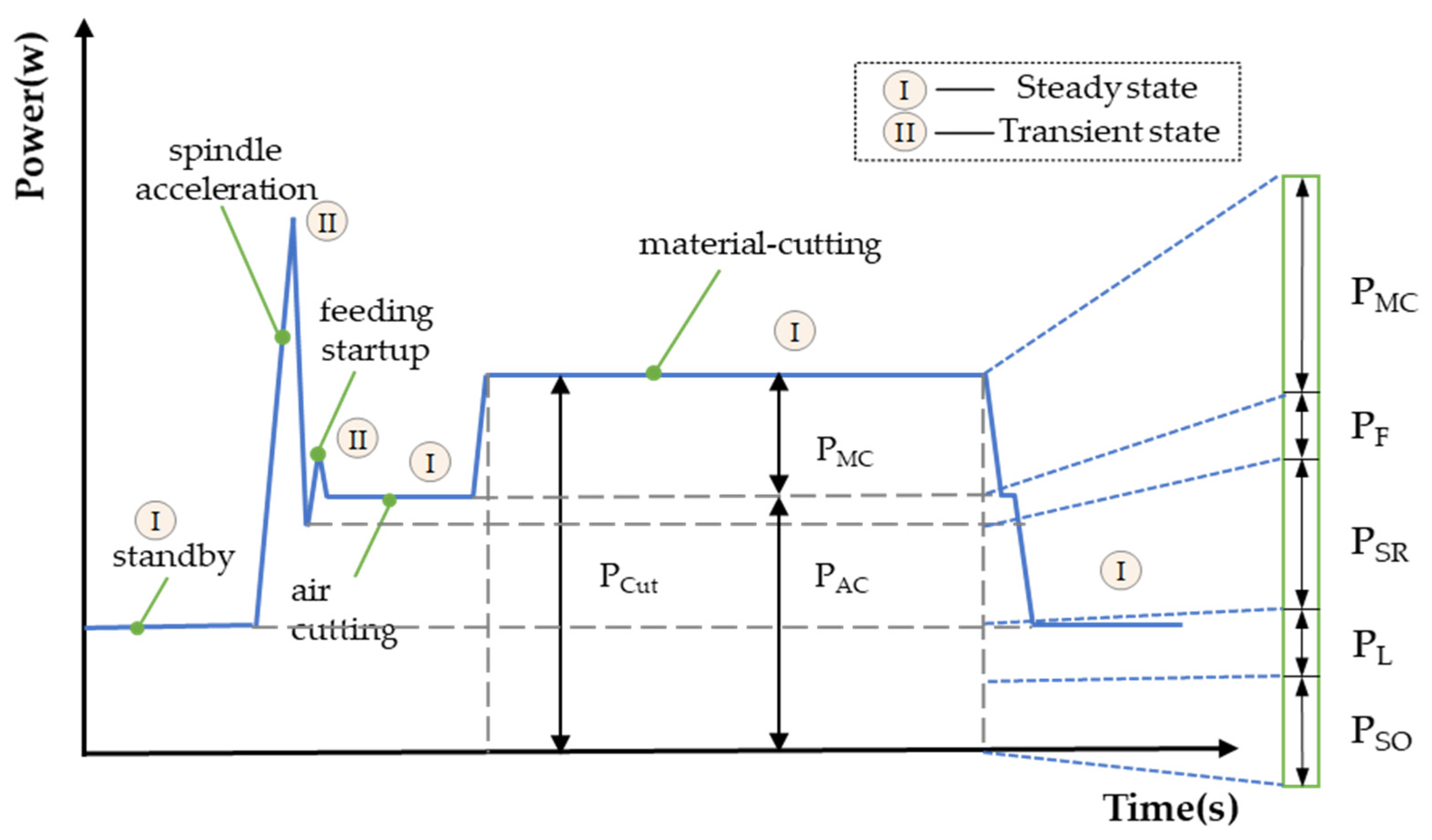
The CNC lathe machining process involves standby, no-load and a cutting state. When the lathe is in the cutting state, the total power at this time is called the cutting power ( P C u t ). The total cutting power is composed of the power of material cutting ( P M C ) and power of air cutting ( P A C ), as shown in Figure 3. The air cutting power refers to the power of the CNC lathe when it moves according to the specified cutter path (without touching the workpiece). The material cutting power refers to the power increased by cutting the workpiece material basis on the air cutter power (the difference between the total cutting power and the air cutting power) [36]. Therefore, the total cutting power can be expressed as:
P C u t = P A C + P M C
where P C u t is the cutting power, W ; P A C is the air cutting power, W ; and P M C is the material cutting power, W .
The power of the air cutting is further decomposed into standby operating power, machine tool lighting power, spindle rotating power and feeding power. Therefore, the power of the air cutting can be further expressed as:
P A C = P S O + P L + P S R + P F
where P S O is the standby operating power, W ; P L is the machine tool lighting power, W ; P S R is the spindle rotating power, W ; and P F is the feeding power, W .
According to Equations (1) and (2), the cutting power can be further expressed as:
P C u t = P S O + P L + P S R + P F + P M C
Next, the functional models of the standby operating power ( P S O ), machine tool lighting power ( P L ), spindle rotating power ( P S R ), feeding power ( P F ) and material cutting power ( P M C ) are introduced, one by one.
(1). Standby operating power
The standby power refers to the power required by the basic modules (including control panel, fan, etc.) to ensure the operation of the machine tool. For a given machine tool, this power is regarded as a fixed value. The standby power can be obtained by pre-measurement combined with the following formula [37]:
P S O = i = 1 N S O P S O , i / N S O
where P S O is the standby operating power, W ; P S O , i is the standby operation power value measured for the i-th time, W ; and N S O is the number of times to measure the standby operating power.
(2). Machine tool lighting power
The lighting power of the machine tool is the power required to maintain the lighting demand of the machine tool. When the model of the machine tool is determined, the lighting power of the machine tool is equal to the rated power of the lighting device of the machine tool, and the function expression is [37]:
P L = P L r
where P L is the lighting power of the machine tool, W ; and P L r is the rated power of the lighting device of the machine tool, W .
(3). Spindle rotating power
The spindle rotating power is the power required to ensure spindle rotation. Based on our previous research results, the spindle rotating power can be written as a linear piecewise function of speed [35]:
P S R = { A s p 1 × n + B s p 1   , 0 < n n 1 A s p 2 × n + B s p 2   , n 1 < n n 2 A s p 3 × n + B s p 3   , n 2 < n n 3
where P S R is the spindle rotation power, W ; n is the spindle speed, r / min ; and A s p 1 , A s p 2 , A s p 3 , B s p 1 , B s p 2 and B s p 3 are the coefficients of the function, which are obtained through experimental measurement and statistical analysis.
(4). Feeding power
The feed power refers to the power consumed by the feed device when feeding. The feed power is related to the performance parameters and operating parameters of the CNC machine tool itself. During feed execution, the power includes two parts: loss power of the feed motor itself and output power of the feed motor shaft. According to our previous research results, the feed power is expressed as a quadratic function of the feed speed [38]:
P X F = C x 0 + C x 1 v x f + C x 2 v x f 2 P Y F = C y 0 + C y 1 v y f + C y 2 v y f 2 P Z F = C z 0 + C z 1 v z f + C z 2 v z f 2
where P X F , P Y F and P Z F are the feed power of the X, Y and Z axes of the CNC lathe, W ; C x 0 , C y 0 and C z 0 are constant terms; and C x 1 , C x 2 , C y 1 , C y 2 , C z 1 and C z 2 are coefficients, which are obtained according to experimental measurement and statistical analysis.
(5). Material cutting power
The material cutting power is one of the most complex parts of the total cutting power of the CNC lathe. According to our previous research results, the function can be expressed as [35]:
P M C = C P · v c n P · f y P · a p x P
where P M C is the material cutting power, W ; C P is the coefficient of the material cutting power; v c is the cutting speed, m / min ; f is the feed rate, mm / r ; a p is the cutting depth, mm ; and n p , y p and x p are the indexes of cutting speed, feed rate and cutting depth, respectively.
According to the above power function models (1) to (8), the steady state process energy consumption function model in the CNC turning process can be calculated:
E s t e a d y = E S O + E L + E S R + E F + E M C = 0 t S O P S O d t + 0 t L P L r d t + 0 t S R ( A S P × n + B S P ) d t + 0 t F ( C 0 + C 1 v f + C 2 v f 2 ) d t + 0 t M C C P · v c n P · f y P · a p x P d t
where E s t e a d y is the energy consumption in the steady state process of CNC turning, J ; E S O is the standby energy consumption of the machine tool, J ; E L is the lighting energy consumption of the machine tool, J ; E S R is the rotation energy consumption of the machine tool spindle, J ; E F is the feed energy consumption of the machine tool, J ; and E M C is the material cutting energy consumption, J .

2.2.2. Transient State Process Energy Consumption Model

For the modeling of the transient process energy consumption, the energy demand generated by spindle acceleration and rapid positioning accounts for the majority of the energy demand generated by the transient process. Therefore, in this paper, the key transient process energy consumption is selected as the research object to establish the transient process energy consumption model.
(1). Spindle acceleration
Spindle acceleration refers to the transfer process of spindle acceleration from low speed to high speed under the condition of no cutting load. The energy demand of the process includes three parts: (1) the energy demand of the spindle system from the beginning of spindle acceleration to the peak power; (2) the energy demand of spindle system during the transition from power peak to power stability; and (3) the basic energy demand during spindle acceleration. According to our previous research, the energy demand for spindle acceleration can be expressed as [39]:
E S R A = E S R 1 + E S R 2 + E S R 3 = 0 t S R 1 P S R 1 d t + 0 t S R 2 P S R max + P S R ( n 2 ) 2 d t + 0 t S R 3 [ P S O + P L + ] d t = 0 t S R 1 [ P S R ( n 1 + 30 α t / π ) + T s ( π n 1 / 30 + α t ) ] d t + 0.5 [ P S R ( n 1 + 30 α t S R 1 / π ) + T s ( π n 1 / 30 + α t S R 1 ) + P S R ( n 2 ) ] t S R 2 + 0 t S R 3 [ P S o + P L + ] d t
where E S R A is the energy consumption during spindle acceleration, J ; P S R is the spindle rotation power, W ; α is the acceleration angle of the spindle, rad / s 2 ; T s is the acceleration torque equivalent to the spindle of the spindle system, N m ; t S R 1 is the time from the start of spindle acceleration to the power peak stage, s ; t S R 2 is the time of transition from the power peak to the stable power period, which is the time of this stage, s ; t S R 3 is the spindle acceleration process time, s ; n 1 is the initial speed of spindle acceleration, r / min ; and n 2 is the target speed, r / min .
(2). Rapid positioning
Rapid positioning refers to the transfer process of the feed system from low feed speed to maximum feed speed. For a given feed system, the maximum feed speed of each axis is determined. The energy demand of the process includes two parts: (1) the energy demand of the feed system in the process of rapid positioning, and (2) the basic energy demand in the rapid positioning process. According to our previous research, the energy demand of the rapid positioning process can be expressed as [39]:
E F A = E F 1 + E F 2 = 0 t F A [ P F + P S O + P L + P S R + ] d t
where E F A is the energy consumption in the rapid positioning process, J , and t F A is the rapid positioning process time, s .
According to the above function models (10) to (11), the energy consumption function model of transient process in CNC turning can be obtained:
E t r a n s i e n t = E S R A + E F A = 0 t S R 1 [ P S R ( n 1 + 30 α t / π ) + T s ( π n 1 / 30 + α t ) ] d t + 0.5 [ P S R ( n 1 + 30 α t S R 1 / π ) + T s ( π n 1 / 30 + α t S R 1 ) + P S R ( n 2 ) ] t S R 2 + 0 t S R 3 [ P S o + P L + ] d t + 0 t F A [ P F + P S O + P L + P S R + ] d t
where E t r a n s i e n t is the energy consumption in the transient process of CNC turning, J .
Therefore, based on the above discussion, the transient-steady state energy consumption function model of the CNC turning process is further obtained according to functional models (9) and (12):
E a = E s t e a d y + E t r a n s i e n t = E S O + E L + E S R + E F + E M C + E S R A + E F A = 0 t S O P S O d t + 0 t L P L r d t + 0 t S R ( A S P × n + B S P ) d t + 0 t F ( C 0 + C 1 v f + C 2 v f 2 ) d t + 0 t M C C P · v c n P · f y P · a p x P d t + 0 t S R 1 [ P S R ( n 1 + 30 α t / π ) + T s ( π n 1 / 30 + α t ) ] d t + 0.5 [ P S R ( n 1 + 30 α t S R 1 / π ) + T s ( π n 1 / 30 + α t S R 1 ) + P S R ( n 2 ) ] t S R 2 + 0 t S R 3 [ P S o + P L + ] d t + 0 t F A [ P F + P S O + P L + P S R + ] d t

3. Multi-Objective Optimization Model

3.1. Selection of Optimization Variables

There are many variable factors involved in the process of CNC lathe machining. In theory, when the manufacturing conditions are determined, the three main factors affecting the optimization goal are spindle speed, feed rate and cutting depth. The reasonable selection of cutting three elements has a great influence on the energy consumption and quality of machining and is the main optimization variable. Therefore, the optimization variables in this paper are spindle speed, feed rate and cutting depth.

3.2. Selection of Optimization Objectives

3.2.1. Optimization Objectives of Low Energy Consumption

This paper takes energy saving in the machining process of CNC lathe as one of the optimization objectives (low energy consumption). Compared with the previous energy consumption models, the energy consumption model in this paper not only takes into account the steady state energy consumption in the CNC machine tool machining process, but also takes into account the transient energy consumption, which is more consistent with the actual situation and has a higher accuracy in energy consumption prediction. According to the above analysis, the transient-steady state energy consumption function model of the CNC machine tool can be expressed as:
E a = E s t e a d y + E t r a n s i e n t = E S O + E L + E S R + E F + E M C T + E S R A + E F A
where E a , E s t e a d y and E t r a n s i e n t are transient-steady state energy consumption, steady state process energy consumption and transient state process energy consumption of the CNC lathe, J .

3.2.2. Optimization Objectives of High Quality

The machining quality of parts is directly related to the working performance and service life of mechanical products. High quality machining is another optimization objective of this paper. The quality of a part is usually expressed by its surface roughness. Surface roughness refers to the dimensional characteristics of microscopic geometry with small spacing and small valleys on the machined surface. These small geometric errors are called surface roughness. Commonly used mathematical models for surface roughness of workpiece are exponential and linear functions as follows [40]:
R a = C 1 v c α a ρ β f δ R a = C 2 + C 3 v c + C 4 a p + C 5 f + C 6 v c + C 7 v c a p + C 8 a p f
where C 1 , C 2 , C 3 , C 4 , C 5 , C 6 , C 7 , C 8 , α , β , and δ are coefficients; v c is the cutting speed, mm/s; f is the feed rate, mm/r; and a p is the cutting depth, mm.
Under the experimental data, the precision of the primary function form model is higher, so this paper uses the primary function form surface roughness model of the workpiece.

3.3. Constraint Condition

The selection of the processing parameters needs to consider the performance requirements of the processing system and the technical requirements of the workpiece, such as the performance range of CNC, the durability of the tool, etc., which should only be used within the limited conditions. Therefore, the constraints for the optimization of cutting parameters should be established according to the actual conditions so that the optimization results obtained by the algorithm can meet the actual production requirement.
(1) Spindle speed constraint: n min n n max , where n , n min and n max are the spindle speed of the CNC lathe, the minimum speed allowed by the CNC lathe and the maximum speed allowed by the CNC lathe, respectively.
(2) Feed speed constraint: v f min v f v f max , where v f , v f min and v f max are the feed speed, the minimum feed speed allowed by the lathe and the maximum feed speed allowed by the lathe, respectively.
(3) Cutting depth constraint: 0 < a p a p max , where a p and a p max are the cutting depth and the maximum allowable cutting depth, respectively.
(4) Tool durability constraint [41]: T = C T v c x f y a p z T B , where T is the tool durability and C T is the tool durability coefficient, which is related to tool, workpiece material and cutting conditions; x, y and z respectively represent the influence of processing parameters v c , f and a p on tool durability. T B is the reasonable durability of the tool.
(5) Maximum power constraint: P s p i n d l e P r a t e d , where P s p i n d l e and P r a t e d are the maximum power of the CNC lathe spindle and the rated power of the CNC lathe spindle motor, respectively.
Based on the above discussion, the multi-objective optimization model of the CNC lathe processing parameters for high quality and low energy consumption is as follows:
min F ( n , f , a p ) = ( min E a , min R a ) s . t . { n min n n max v f min v f v f max 0 < a p a p max T = C T v c x f y a p z T B P s p i n d l e P r a t e d

4. Model Solving Based on NSGA-II

When solving the multi-objective optimization model, the more popular and mature NSGA-II algorithm is used. NSGA-II is one of the most popular multi-objective genetic algorithms. It reduces the complexity of the non-inferior classification genetic algorithm and has the advantages of fast running speed and good convergence of the solution set [42].

4.1. The Flow of NSGA-II

The main process of the NSGA-II algorithm is as follows:
(1) The initial parent population P ( 0 ) with population size S is randomly generated, and the child population Q ( 0 ) is obtained after non-dominated sorting, and set up as g = 0 .
(2) The above two generations are combined to form a new population R ( g ) .
(3) At the same time of the non-dominated sorting of population R ( g ) , the crowding degree of each front-end individual is calculated, and the best individual is selected according to the order value and crowding degree of the individual to form a new parent group P ( g + 1 ) .
(4) P ( g + 1 ) is selected, hybridized and mutated to produce a new offspring population Q ( g + 1 ) .
(5) Judge whether the termination condition is true. Otherwise, g = g + 1 , go back to (2).

4.2. The Application and Parameter Setting of NSGA-II

4.2.1. The Application of NSGA-II

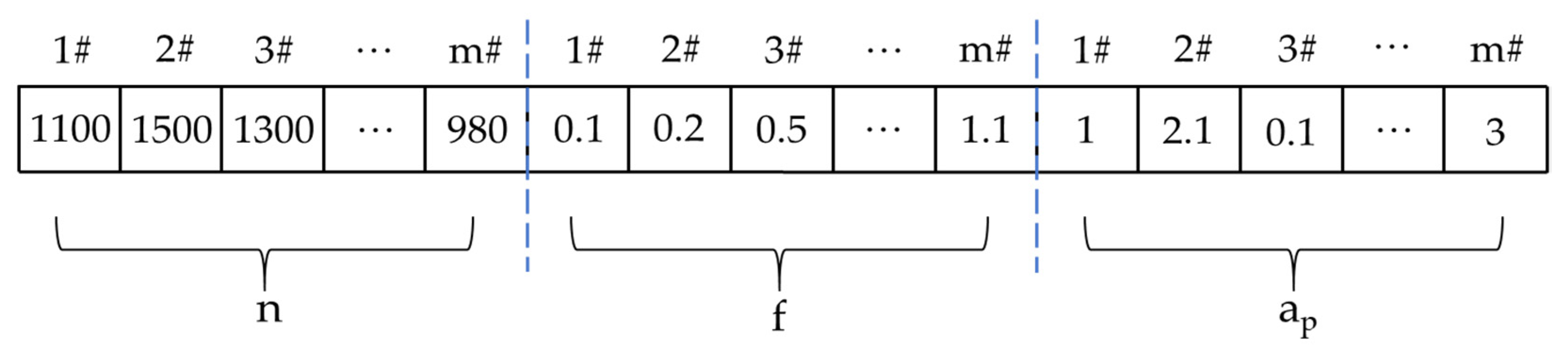
(1). Chromosome coding
In the optimization solution, the mathematical expression of the model should be coded according to the programming method. In this paper, the optimization variables are spindle speed n , feed rate f and cutting depth a p . So, this paper adopts real number coding. As shown in Figure 4, chromosomes with a length of 3 × m are generated by random generation. The first part is the spindle speed n , the second part is the feed rate f , and the third part is the cutting depth a p . According to the specific constraints, the value range of each variable is given.
(2). Initial population
Initial filling is the starting point of the algorithm, and good initial filling can improve the efficiency of the algorithm. In this algorithm, the initial population is generated randomly, but the range can be limited by constraints to obtain a better initial population.
The value range of population size M is generally between 20 and 500. The variable parameters mainly involved in this paper are three real values, and the chromosome length is general because the value of population size in this paper is 300.
(3). Fitness calculation
In the NSGA-II algorithm, individual fitness is calculated by the non-dominated level and congestion distance. Firstly, the double objective function value of each individual in the population is calculated, and then all individuals in the population are divided into different non-dominated grades by the non-dominated classification method. All non-dominated optimal solutions in the current population are regarded as the first non-dominated optimal solution level, and the non-dominated level of each individual is designated as level 1. Similarly, the remaining individuals in the population are classified and assigned values until all individuals are divided into different levels. It should be noted that the smaller the grade value, the better the individual.
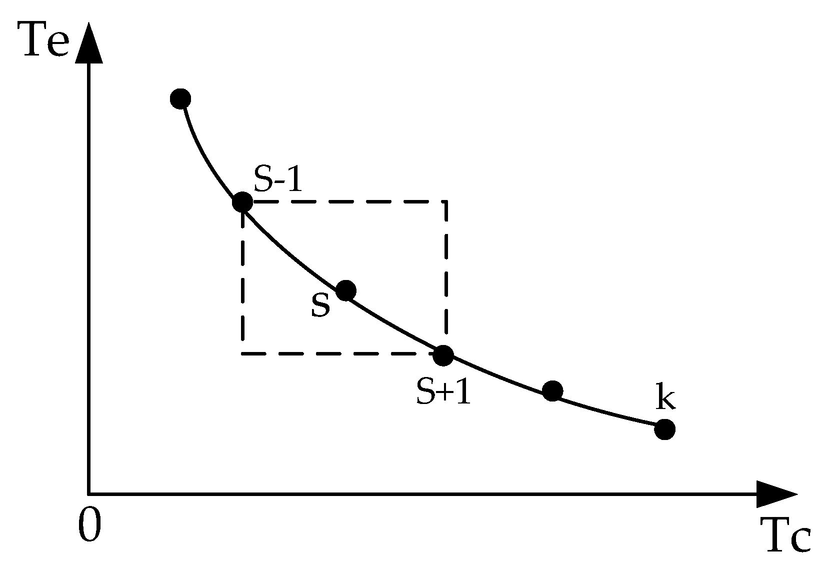
The crowding distance refers to the distance between individuals at the same level. As shown in Figure 5, it refers to the sum of the relative distances between an individual in the target space and two adjacent individuals at the same level in each objective function.
At the same level, there are several individuals. In order to ensure that marginal individuals have a choice advantage, the crowding distance is set to the maximum. For intermediate individuals, the formula of the crowding distance is as follows:
L r ( s ) = L r ( s ) + | L r ( s + 1 ) L r ( s 1 ) | L r ( k )
where L r ( s ) is the crowding degree of the s-th individual on the objective function of r.

4.2.2. The Parameter Setting of NSGA-II

This paper mainly uses the NSGA-II algorithm in the geatpy library with the help of the Python 3.8 platform. Geatpy is a high-performance and practical evolutionary algorithm toolbox. It provides many library functions of important operations in the implemented evolutionary algorithms and provides a highly modular and low coupling object-oriented evolutionary algorithm framework. It adopts the mode of "defining problem class + calling algorithm template" for evolutionary optimization, which can be used to solve constraint optimization, combinatorial optimization, hybrid coding evolutionary optimization and so on.

4.3. Weight of Multi-Objective Optimization

In this paper, when solving the corresponding multi-objective model through NSGA-II, we obtain a set of solutions, which cannot give the corresponding optimal solution. Different target weight settings will bring different solutions, and the setting of the weight is particularly important. This paper mainly determines the corresponding target weight through the correlation between optimization objectives and optimization variables. In this paper, the grey correlation degree analysis method is used to calculate the grey correlation coefficient of each target and obtain the target weight so as to optimize the target and obtain the corresponding processing parameters. Combined with the actual data and the value in the optimization, the grey correlation analysis is carried out. The main steps are as follows:
(1). Standardize the objective function to eliminate the influence of different orders of magnitude [43].
Z i j - max = y i j min ( y i j , i = 1 , 2 , , n ) max ( y i j , i = 1 , 2 , , n ) min ( y i j , i = 1 , 2 , , n ) Z i j - min = max ( y i j , i = 1 , 2 , , n ) y i j max ( y i j , i = 1 , 2 , , n ) min ( y i j , i = 1 , 2 , , n )
among them, the formula of Z i j - max is used when the objective function takes the maximum as the optimal, and the formula of Z i j - min is used when the objective function takes the minimum as the optimal. In this formula, n is the number of experimental data sets and m is the number of optimization objectives.
(2). Calculate the grey correlation coefficient of the standardization target.
γ ( Z o , Z i j ) = Δ min + β Δ max Δ o j ( k ) + β Δ max
where Z o ( k ) is the reference sequence and Δ o j ( k ) is the Z o ( k ) deviation sequence from the comparison sequence Z i j ( k ) . β is the resolution coefficient, and the value range is 0 < β < 1 .
(3). Multi-objective weight calculation.
In this paper, in the multi-objective weight determination, the influence of the optimization of processing parameters on the optimization target is used as the standard to determine the target weight. The weight coefficient is calculated as follows:
ω = j = 1 p R i j i = 1 m j = 1 p R i j
among them, R i j = max { K i j , 1 , K i j , 2 , , K i j , k } min { K i j , 1 , K i j , 2 , , K i j , k }
where m is the number of optimization objectives, R is the range of grey correlation coefficients, K is the average grey correlation number of each processing process parameter at each level, and ω is the weight of objectives. In the later optimization process, combined with the actual optimization objectives, different weights are given.

5. Case Study

To demonstrate the effectiveness and feasibility of the proposed approach, an actual machining case is conducted and analyzed in this case study. Firstly, taking a shaft part processed by the CK6153i CNC lathe as the test object, the importance of considering the transient state energy consumption is illustrated (the workpiece is shown in Figure 6). Secondly, taking the finish turning process in the machining process as an example, the optimization of the machining process parameters is studied. During the processing, the power and energy data were simultaneously measured by a power-energy collecting system established by our research group (Figure 7). For more information about the power-energy collecting system, refer to Ref. [44].

5.1. Experimental Conditions

The geometric parameters of VNMG160408MV tool and main technical parameters of CK6153i CNC lathe are shown in Table 1 and Table 2.

5.2. Experimental Study

In order to illustrate the importance of considering transient state energy consumption, our research group conducted many experiments before. Taking a shaft part processed by the CK6153i CNC lathe as the test object, the shaft part is machined through five main cutting processes (dry cutting): (a) end-face turning, (b) rough turning, (c) finish turning, (d) chamfer turning, and (e) grooving. The power and energy data are simultaneously measured by the power-energy collecting system mentioned earlier. The results are shown in Figure 8.
Figure 8 shows the predicted and measured power curve of the machining case. It can be seen that the predictive power curve with the energy of the transient state can display the power peaks during the machining case. The predicted power curve with energy of transient state can match the measured power curve better than the predicted power curve without the energy of the transient state. Considering the transient state energy consumption can improve the integrity of the energy consumption models of the entire machining process and improve the forecasting accuracy of the energy consumption of the entire machining process. Therefore, the optimization of the processing parameters based on the transient steady state energy consumption model is more effective.

5.3. Multi-Objective Optimization Model

As can be seen in Section 5.2, considering the transient state energy consumption can improve the forecasting accuracy of energy consumption. Therefore, this section considers transient steady state energy consumption to study the optimization of the CNC turning process parameters. At the same time, the main parameters of the machining process under experience are given, as shown in Table 3.

5.3.1. Energy Consumption Model

According to the relevant dimensions of machining shaft parts, the machining process flow of finishing turning excircle in this case can be divided into seven specific steps: (a) executing standby; (b) spindle acceleration from static to 1000 r/min; (c) rapid positioning; (d) feeding; (e) finishing turning; (f) rapid positioning to origin; and (g) executing standby. The energy consumption of the machining process mainly includes two transient processes’ energy consumption (spindle acceleration stage, rapid feed positioning stage) and four steady state processes’ energy consumption (machine tool standby operation stage, feed stage and finish turning excircle cutting stage). According to the construction of the energy consumption model in the previous paper, combined with the experiment of finishing cylindrical machining, the corresponding mathematical function is given.
(1). Executing standby:
In the case, the standby time of the CNC lathe includes two parts: the start part and the end part. That is, the t S O - s t a r t and t S O - f i n i s h processing parameters do not affect this part, so the corresponding time is no different from the traditional processing, namely, 5.0 s, and 5.0 s. After several measurements, the execution standby power of the CNC lathe CK6153i is N S O = 200 , and P S O = 312.1   w . Then, the execution standby energy consumption of the CNC lathe in the embodiment is:
E S O = 2 × 0 t S O P S O d t = 2 × 312.1 × 5 = 3121   J
(2). Spindle acceleration:
According to the previous analysis, the energy demand of the spindle process includes three parts. According to the equipment parameters of CNC lathe CK6153i and through experimental numerical fitting, the piecewise function model of spindle rotation power is obtained as follows:
P S R = { 1.09 n + 41.12   , 0 < n 1000   r / min 0.558 n + 605.05   , 1000 < n 1300   r / min 1.288 n 358.21   , 1300 < n 1500   r / min
At the same time, it can be seen that the time function of spindle acceleration stage is calculated as follows:
t S R 1 = 2 π ( n 1 n 2 ) / 60 α t S R 2 = 0.037 + 1.471 × 10 4 n 2 t S R 3 = t S R 1 + t S R 2
among them, the spindle acceleration angle of the CK61563i CNC lathe is α = 39.78   rad / s ; the acceleration torque of the spindle is T s = 28.42   N · m .
To sum up, according to Formulas (10), (22) and (23), the energy consumption function of the spindle acceleration part can be obtained as follows:
E S R A = E S R 1 + E S R 2 + E S R 3 = { 5.35 × 10 3 n 2 + 0.11 n , 0 < n 1000 4.65 × 10 3 n 2 + 1.59 n , 1000 < n 1300 5.61 × 10 3 n 2 0.94 n , 1300 < n 1500 + { ( 1.47 × 10 4 n + 0.037 ) × ( 2.58 n + 41.12 ) , 0 < n 1000 ( 1.47 × 10 4 n + 0.037 ) × ( 2.05 n + 605.05 ) , 1000 < n 1300 ( 1.47 × 10 4 n + 0.037 ) × ( 2.78 n 358.21 ) , 1300 < n 1500 + 0.92 n + 12.29 = { 5.73 × 10 3 n 2 + 1.13 n + 13.81 , 0 < n 1000 4.95 × 10 3 n 2 + 2.68 n + 34.67 , 1000 < n 1300 6.02 × 10 3 n 2 + 0.03 n 0.97 , 1300 < n 1500
(3). Rapid positioning:
In this case, there are two main processes of rapid positioning: rapid positioning from the origin to the safe processing position. After machining, the tool is quickly positioned to the origin. For a given feed system, the maximum feed speed of each axis is determined. The maximum feed speeds of the X-axis and Z-axis of the CK6153i CNC lathe are 6000   mm / min and 10,000   mm / min , respectively. In reference, the fast feed power in direction and Z direction can be obtained through experimental measurement and statistics, which can be expressed as P F A X = 781.33   w , and P F A Z = 874.35   w . In this experimental case study, two rapid positioning processes are included, and the distance corresponding to the process is shown in Table 4.
According to Formula (11), the energy consumption generated in the rapid positioning stage in this case design is as follows:
E F A = 0 t F A ( P X F + P S O + P S R ) d t = 0 0.25 ( 781.33 + 847.35 + 312.1 + P S R ( n ) ) d t + 0 0.32 ( 874.35 + 312.1 + P S R ( n ) ) d t + 0 0.2 ( 781.33 + 847.35 + 312.1 + P S R ( n ) ) d t + 0 0.544 ( 874.35 + 312.1 + P S R ( n ) ) d t = { 1.43 n + 1929.15 , 0 < n 1000   r / min 0.73 n + 2670.15 , 1000 < n 1300   r / min 1.69 n + 1404.43 , 1300 < n 1500   r / min
(4). Feeding:
This stage means that after the tool is quickly positioned to the safe cutting position, the tool is slowly close to the material at the cutting feed speed so as to prepare for the next finishing excircle cutting. In this case design, it mainly includes two parts: x-feed and z-feed. According to the power model of the CNC lathe mentioned above and combined with the experimental data, the feed power functions in X and Z directions of CK6153i can be obtained as follows:
P X F = 1.63 + 0.017 v z f + 4.24 × 10 6 v x f 2 P Z F = 0.49 + 0.030 v z f + 2.32 × 10 6 v z f 2
At the same time, the feed distance in the x-axis direction is l x = 2.5   mm and the feed time can be expressed as t x f = l x / v x f = 3   s . If the feed distance in the z-axis direction is l z = 5   mm , the feed time in this stage can be expressed as t z = l z / v z f = 5 / v z f .
Therefore, to sum up, the energy consumption in the feeding stage can be expressed as:
E F = 0 t x f P X F d t + 0 t z f P Z F d t = 1.93 × 10 7 n · f + 147 ( n · f ) 1 2.16
(5). Finish turning:
According to the power model of the lathe outer circle in the previous paper and combined with the actual experimental data of CK6153i, the power function model of the lathe outer circle in this process can be fitted as follows:
P M C = 44.57 · v c 0.909 · f 0.657 · a p 0.917
Accordingly, the cutting time at this stage is t = l / v f = 24 / v f . The energy consumption function model of the finish turning outer circle can be obtained as follows:
E c u t = 0 t P A C d t + 0 t P M C d t = 0 24 v f ( 312.1 + 1.09 n + 41.12 1.63 + 0.017 v f + 4.24 × 10 6 v f 2 ) + 0 24 v f ( 110.61 · a p 0.917 · n 0.252 · v f 0.657 ) d t = ( 2654.62 · a p 0.917 · n 0.252 · v f 0.657 + 26.16 n + 1.02 × 10 4 v f 2 + 8438.16 ) / v f
where E c u t is the energy consumption value of the CNC lathe finish turning excircle cutting, J ; P A C is the auxiliary power in the cutting process of the CNC lathe, W ; and P M C is the material cutting power of the CNC lathe, W .
Combining the above energy consumption mathematical functions, the mathematical function of the total energy consumption in the processing process in this case can be obtained.
E a = E S O + E S R A + E F A + E F + E c u t = { 10,812.07 n 0.091 f 0.343 a p 0.917 + 1.89 × 10 6 n f + 5.73 × 10 3 n 2 + 2.56 n + 1569.9 f 1 + 506,436.6 × ( n f ) 1 + 5062.21 , 0 < n 1000 10,812.07 n 0.091 f 0.343 a p 0.917 + 1.89 × 10 6 n f + 4.95 × 10 3 n 2 + 3.41 n + 1569.9 f 1 + 506,436.6 × ( n f ) 1 + 5824.08 , 1000 < n 1300 10,812.07 n 0.091 f 0.343 a p 0.917 + 1.89 × 10 6 n f + 6.02 × 10 3 n 2 + 1.72 n + 1569.9 f 1 + 506,436.6 × ( n f ) 1 + 4522.71 , 1300 < n 1500
It can be obtained that under the empirical processing process parameters, that is, the spindle speed is n = 1000   r / min , the feed rate f = 0.1   mm / min , and the cutting depth a p = 0.5   mm , the total energy consumption in the processing process is E a = 40,845   J .
At the same time, it can be obtained that the proportion of transient process energy consumption in the total energy consumption in this embodiment is 16.84%, as shown in Figure 9. Obviously, the energy consumption of transient process is relatively high, which cannot be ignored.

5.3.2. Surface Roughness Model

In this paper, the workpiece is 45# steel and the tool is VNMG160408MV. By inquiring the requirements of relevant process parameters, empirical values and the research on surface roughness in Ref. [40], the surface roughness in this paper is as follows:
R a = 4.12 × 10 4 n · a p + 2.78 × 10 2 f 1.01 × 10 3 n + 1.5985
It can be obtained that under the traditional processing parameters, the spindle speed n = 1000   r / min , feed rate f = 0.1   mm / min , and cutting depth a p = 0.5   mm , at which time the surface roughness is:
R a = ( 1000 , 0.1 , 0.5 ) = 0.7968   μ m

5.3.3. Constraint Condition

According to the constraints mentioned above, combined with the geometric parameters of VNMG160408MV tool in Table 1 and the technical specification parameters of the CK6153i CNC lathe in Table 2, and according to the actual cases in this paper, the specific range of constraints in this paper can be obtained, as shown in Table 5.

5.3.4. Optimization Model

In summary, the multi-objective optimization model can be expressed as:
{ min E a ( n , f , a p ) = { 10,812.07 n 0.091 f 0.343 a p 0.917 + 1.89 × 10 6 n f + 5.73 × 10 3 n 2 + 2.56 n + 1569.9 f 1 + 506,436.6 × ( n f ) 1 + 5062.21 , 0 < n 1000 10,812.07 n 0.091 f 0.343 a p 0.917 + 1.89 × 10 6 n f + 4.95 × 10 3 n 2 + 3.41 n + 1569.9 f 1 + 506,436.6 × ( n f ) 1 + 5824.08 , 1000 < n 1300 10,812.07 n 0.091 f 0.343 a p 0.917 + 1.89 × 10 6 n f + 6.02 × 10 3 n 2 + 1.72 n + 1569.9 f 1 + 506,436.6 × ( n f ) 1 + 4522.71 , 1300 < n 1000 min R a ( n , f , a p ) = min ( 4.12 × 10 4 n · a p + 2.78 × 10 2 f 1.01 × 10 3 n + 1.5985 ) s . t . { 100 n 1500   r / min 0.10 f 2   mm / r 0.10 a p 5   mm

5.4. Model Solving Based on NSGA-II

During the double objective optimization, the NSGA-II algorithm is used to solve the model. Referring to previous literature studies and cases, we preliminarily set the relevant operation parameters, and through multiple operations, we set the relevant parameters in the NSGA-II algorithm as shown in Table 6.
After the algorithm parameters are set, the algorithm is called several times to solve the objective function, and the Pareto curve is obtained as shown in Figure 10. It can be seen that in the optimization of processing parameters for high quality and energy saving, the value of the optimization objective function conforms to the Pareto curve, and the discontinuity of the curve is caused by the subsection function of the spindle power. The partial values display of the Pareto solution set are shown in Table 7.

5.5. Results and Discussions

In addition, to demonstrate the benefits of considering transient state energy consumption, we also solve the multi-objective optimization model without considering transient energy consumption. For multi-objective optimization, the final result is selected from the Pareto front with a preference of low energy consumption. The results of the empirical turning, multi-objective optimization (without energy of transient state), and multi-objective optimization (with energy of transient state) listed in Table 8 are summarized in Figure 11 for a comparison among different schemes.
As can be seen from Figure 11, comparing the objective function values of different schemes, the optimization results considering transient state energy consumption are significantly better than those without transient state energy consumption, especially for the energy-saving optimization objectives. For the optimization scheme considering transient state energy consumption, when the spindle speed n = 1500   r / min , feed rate f = 1.1   mm / r and cutting depth a p = 0.5   mm , the objective function value obtains the optimal value. Moreover, the energy consumption value is 38.3% lower than that under empirical process parameters, and the surface roughness is 47.0%. For the optimization scheme without considering transient state energy consumption, when the spindle speed n = 1500   r / min , feed rate f = 0.4   mm / r and cutting depth a p = 0.5   mm , the objective function value obtains the optimal value. Moreover, the energy consumption value is 28.7% lower than that under empirical process parameters, and the surface roughness is 49.3%.
In addition, it is worth noting that the surface roughness value under the optimization scheme considering transient state energy consumption is slightly worse than that without transient state energy consumption. The main reason is that the large feed speed leads to poor machining quality. However, the effect of energy consumption optimization is much higher than that without considering transient state energy consumption. It can be seen that parameter optimization based on the high-precision energy consumption model has more advantages.

6. Conclusions

In this paper, the energy consumption composition characteristics of the CNC lathe machining process are analyzed, and the energy consumption of the transient process is introduced into the energy consumption model of the CNC lathe, which further improves the accuracy of the model. A multi-objective optimization model is established, taking the spindle speed, feed rate and cutting depth as optimization variables, and high-quality and low-energy machining as optimization objectives. The above model is optimized by using the non-dominated sorting genetic algorithm with elite strategy. Through case analysis, the optimization results show that it can greatly reduce the machining energy consumption and workpiece surface roughness.
Energy modeling and parameter optimization of turning were the focuses of this research. The main limitation of this study is that the influence of the cutting tools was not considered. Hence, the integrated optimization of machining tools and process parameters will be the research object in our future work.

Author Contributions

Conceptualization, S.J. and J.L.; methodology, W.C.; software, S.W.; validation, S.J., S.W. and N.Z.; formal analysis, Z.Z.; investigation, S.B.; resources, S.J.; data curation, N.Z.; writing—original draft preparation, S.J. and S.W.; writing—review and editing, S.J.; visualization, J.L.; supervision, W.C.; project administration, Z.Z.; funding acquisition, S.B. All authors have read and agreed to the published version of the manuscript.

Funding

This research was funded by the National Natural Science Foundation of China (Grant No. 71971130; 71701113), the Project of Shandong Province Higher Educational Science and Technology Program (Grant No. J17KA167), the Key Science and Technology Program of Henan Province (Grant No. 212102210357). This research is also supported by SDUST Research Fund (Grant No. 2018YQJH103).

Institutional Review Board Statement

Not applicable.

Informed Consent Statement

Not applicable.

Data Availability Statement

Not applicable.

Acknowledgments

We deeply appreciate the valuable contribution of the reviewers and editors of sustainability. Their professional suggestions on the manuscript helped us greatly improve the quality of this article.

Conflicts of Interest

The authors declare no conflict of interest.

References

  1. Liu, F.; Liu, P.; Li, C.; Tuo, J.; Cai, W. The statue and difficult problems of research on energy efficiency of manufacturing systems. J. Mech. Eng. 2017, 53, 1–11. [Google Scholar] [CrossRef]
  2. Liu, F.; Wang, Q.; Liu, G. Content architecture and future trends of energy efficiency research on machining systems. J. Mech. Eng. 2013, 49, 87–94. [Google Scholar] [CrossRef]
  3. Jia, S.; Cai, W.; Liu, C.; Zhang, Z.; Hu, L. Energy modeling and visualization analysis method of drilling processes in the manufacturing industry. Energy 2021, 228, 120567. [Google Scholar] [CrossRef]
  4. Jia, S.; Yuan, Q.; Cai, W.; Li, M.; Li, Z. Energy modeling method of machine-operator system for sustainable machining. Energy Convers. Manag. 2018, 172, 265–276. [Google Scholar] [CrossRef]
  5. Kminiak, R.; Dzurenda, L. Impact of Sycamore Maple Thermal Treatment on a Granulometric Composition of Chips Obtained due to Processing on a CNC Machining Mentre. Sustainability 2019, 11, 718. [Google Scholar] [CrossRef] [Green Version]
  6. Zhang, C.; Jiang, P. Sustainability Evaluation of Process Planning for Single CNC Machine Tool under the Consideration of Energy-Efficient Control Strategies Using Random Forests. Sustainability 2019, 11, 3060. [Google Scholar] [CrossRef] [Green Version]
  7. Xiao, Y.; Jiang, Z.; Gu, Q.; Yan, W.; Wang, R. A novel approach to CNC machining center processing parameters optimization considering energy-saving and low-cost. J. Manuf. Syst. 2021, 59, 535–548. [Google Scholar] [CrossRef]
  8. Chen, W.; Huang, C.; Yang, Q.; Yang, Y. Optimal prediction and design of surface roughness for CNC turning of al7075-t6 by using the taguchi hybrid QPSO algorithm. T. Can. Soc. Mech. Eng. 2016, 40, 883–895. [Google Scholar] [CrossRef] [Green Version]
  9. Pangestu, P.; Pujiyanto, E.; Rosyidi, C. Multi-objective cutting parameter optimization model of multi-pass turning in CNC machines for sustainable manufacturing. Heliyon 2021, 7, e06043. [Google Scholar] [CrossRef] [PubMed]
  10. Li, L.; Liu, F.; Chen, B.; Li, C. Multi-objective optimization of cutting parameters in sculptured parts machining based on neural network. J. Intell. Manuf. 2015, 26, 891–898. [Google Scholar] [CrossRef]
  11. Moreira, L.; Li, W.; Lu, X.; Fitzpatrick, M. Energy-Efficient machining process analysis and optimisation based on BS EN24T alloy steel as case studies. Robot. Cim-Int. Manuf. 2019, 58, 1–12. [Google Scholar] [CrossRef]
  12. Zhou, J.; Ren, J.; Yao, C. Multi-objective optimization of multi-axis ball-end milling Inconel 718 via grey relational analysis coupled with RBF neural network and PSO algorithm. Measurement 2017, 102, 271–285. [Google Scholar] [CrossRef]
  13. Doriana, M.; D’Addona; Roberto, T. Genetic Algorithm-based Optimization of Cutting Parameters in Turning Processes. Procedia CIRP 2013, 7, 323–328. [Google Scholar]
  14. Pan, B.; Yu, M.; Xiang, Y.; Luo, L.; Ding, W. Accuracy reliability analysis and process optimization design of milling processing considering toll wear. Comput. Integra. Manuf. 2020, 26, 2982–2991. [Google Scholar]
  15. Feng, C.; Chen, X.; Zhang, J.; Huang, Y.; Qu, Z. Minimizing the Energy Consumption of Holes Machining Integrating the Optimization of Tool Path and Cutting Parameters on CNC Machines. Int. J. Adv. Manuf. Technol. 2021. [Google Scholar] [CrossRef]
  16. Jia, S.; Yuan, Q.; Lv, J.; Liu, Y.; Ren, D.; Zhang, Z. Therblig-embedded value stream mapping method for lean energy machining. Energy 2017, 138, 1081–1098. [Google Scholar] [CrossRef] [Green Version]
  17. LI, P. Research on Energy Efficiency Oriented CNC Milling Process Parameters Optimization Model and Method. Master’s Thesis, Chongqing University, Chongqing, China, 2014. [Google Scholar]
  18. Li, C.; Xiao, Q.; Tang, Y.; Li, L. A method integrating Taguchi, RSM and MOPSO to CNC machining parameters optimization for energy saving. J. Clean. Prod. 2016, 135, 263–275. [Google Scholar] [CrossRef]
  19. Tran, C.; Dang, M.; Le, H.; Chau, N.; Dao, T. Optimization of CNC Milling Parameters for Complex 3D Surfaces of SIMOLD 2083 Alloy Mold Core Utilizing Multiobjective Water Cycle Algorithm. Math. Probl. Eng. 2021, 2021, 9946404. [Google Scholar] [CrossRef]
  20. Yang, Y.; Shie, J.; Huang, C. Optimization of Dry Machining Parameters for High-Purity Graphite in End-Milling Process. Mater. Manuf. Process. 2006, 21, 832–837. [Google Scholar] [CrossRef]
  21. Sukumar, M.; Ramaiah, V.; Nagarjuna, A. Optimization and Prediction of Parameters in Face Milling of Al-6061 Using Taguchi and ANN Approach. Procedia Eng. 2014, 97, 365–371. [Google Scholar] [CrossRef] [Green Version]
  22. Li, C.; Xiao, Q.; Li, L.; Zhang, X. Optimization method of NC milling parameters for energy efficiency based on Taguchi and RSM. Comput. Integra. Manuf. 2015, 21, 3182–3191. [Google Scholar]
  23. Liu, Y.; Zhao, C.; Feng, M. Research of Cutting Parameters of High-Speed Milling Based on Orthogonal of Experimental. Modul. Mach. Tool Autom. Manuf. Tech. 2008, 39, 68–71. [Google Scholar]
  24. Wang, Q.; Liu, F.; Wang, X. Multi-objective optimization of machining parameters considering energy consumption. Int. J. Adv. Manuf. Technol. 2014, 71, 1133–1142. [Google Scholar] [CrossRef]
  25. Yan, J.; Li, L. Multi-objective optimization of milling parameters—The trade-offs between energy, production rate and cutting quality. J. Clean. Prod. 2013, 52, 462–471. [Google Scholar] [CrossRef]
  26. Chen, X.; Li, C.; Li, L.; Xiao, Q. Multi-objective parameter optimization model of multi-pass CNC milling for energy efficiency. Comput. Integra. Manuf. 2016, 22, 538–546. [Google Scholar]
  27. Li, C.; Zhu, Y.; Li, L.; Chen, X. Multi-objective optimization model for numerical control milling machining parameters for energy efficiency. J. Mech. Eng. 2016, 52, 130–137. [Google Scholar] [CrossRef]
  28. Arezoo, B.; Ridgway, K.; Al-Ahmari, A. Selection of cutting tools and conditions of machining operations using an expert system. Comput. Ind. 2000, 42, 43–58. [Google Scholar] [CrossRef]
  29. Zhou, Z.; Yang, F.; Huang, W.; Wang, Y.; Tang, A.; Xiao, S. Research on Turning Expert System with Self-learning. J. Hunan Univ: Nat. Sci. Ed. 2010, 37, 24–28. [Google Scholar]
  30. Liu, Y.; Dong, H.; Lohse, N.; Petrovic, S. A multi-objective genetic algorithm for optimisation of energy consumption and shop floor production performance. Int. J. Prod. Econ. 2016, 179, 259–272. [Google Scholar] [CrossRef] [Green Version]
  31. Ma, F.; Zhang, H.; Cao, H.; Hon, K. An energy consumption optimization strategy for CNC milling. Int. J. Adv. Manuf. Technol. 2017, 90, 1715–1726. [Google Scholar] [CrossRef]
  32. Petrovic, M.; Mitic, M.; Vukovic, N.; Miljkovic, Z. Chaotic particle swarm optimization algorithm for flexible process planning. Int. J. Adv. Manuf. Technol. 2016, 85, 2535–2555. [Google Scholar] [CrossRef]
  33. Jia, S.; Tang, R.; Lv, J.; Yuan, Q.; Peng, T. Energy consumption modeling of machining transient states based on finite state machine. Int. J. Adv. Manuf. Technol. 2017, 88, 2305–2320. [Google Scholar] [CrossRef]
  34. He, K.; Hong, H.; Tang, R.; Wei, J. Analysis of Multi-Objective Optimization of Machining Allowance Distribution and Parameters for Energy Saving Strategy. Sustainability 2020, 12, 638. [Google Scholar] [CrossRef] [Green Version]
  35. Jia, S. Research on Energy Demand Modeling and Intelligent Computing of Machining Process for Low Carbon Manufacturing. Master’s Thesis, Zhejiang University, Hangzhou, China, 2014. [Google Scholar]
  36. Li, W.; Kara, S. An empirical model for predicting energy consumption of manufacturing processes: A case of turning process. Proc. I. Mech. Eng. B-J. Eng. 2011, 225, 1636–1646. [Google Scholar] [CrossRef]
  37. Lv, J. Research on Energy Supply Modeling of Computer Numerical Control Machine Tools for Low Carbon Manufacturing. Master’s Thesis, Zhejiang University, Hangzhou, China, 2014. [Google Scholar]
  38. Jia, S.; Yuan, Q.; Cai, W.; Lv, J.; Hu, L. Establishing prediction models for feeding power and material drilling power to support sustainable machining. Int. J. Adv. Manuf. Technol. 2019, 100, 2243–2253. [Google Scholar] [CrossRef]
  39. Jia, S.; Yuan, Q.; Ren, D.; Lv, J. Energy Demand Modeling Methodology of Key State Transitions of Turning Processes. Energies 2017, 10, 462. [Google Scholar] [CrossRef] [Green Version]
  40. Cui, F. Research on NC Turning Parameter Optimization Method for Low Energy Consumption and High Surface Quality. Master’s Thesis, Yanbian University, Yanji, China, 2018. [Google Scholar]
  41. Chen, X.; Li, C.; Jin, Y.; Li, L. Optimization of cutting parameters with a sustainable consideration of electrical energy and embodied energy of materials. Int. J. Adv. Manuf. Technol. 2018, 96, 775–788. [Google Scholar] [CrossRef] [Green Version]
  42. Xu, G.; Chen, J.; Zhou, H.; Yang, J.; Hu, P.; Dai, W. Multi-objective feedrate optimization method of end milling using the internal data of the CNC system. Int. J. Adv. Manuf. Technol. 2019, 101, 715–731. [Google Scholar] [CrossRef]
  43. Fu, Y. Multi-Objective Optimization of Milling Process Parameters for Green High Manufacturing. Master’s Thesis, Hunan University of Science and Technology, Xiangtan, China, 2017. [Google Scholar]
  44. Jia, S.; Tang, R.; Lv, J. Therblig-based energy demand modeling methodology of machining process to support intelligent manufacturing. J. Intell. Manuf. 2014, 25, 913–931. [Google Scholar] [CrossRef]
Figure 1. Application of response surface method and Taguchi method in parameter optimization.
Sustainability 13 13803 g001
Figure 2. Measured power curve of machining process for a shaft part.
Sustainability 13 13803 g002
Figure 3. Power profile of CNC Turning.
Sustainability 13 13803 g003
Figure 4. Chromosome coding.
Sustainability 13 13803 g004
Figure 5. Schematic diagram of congestion distance.
Sustainability 13 13803 g005
Figure 6. Schematic diagram of machining shaft parts.
Sustainability 13 13803 g006
Figure 7. Experimental setup of the power-energy collecting system.
Sustainability 13 13803 g007
Figure 8. Predicted and measured power curve of machining case (CK6153i).
Sustainability 13 13803 g008
Figure 9. Energy consumption ratio of transient process in processing case.
Sustainability 13 13803 g009
Figure 10. Pareto curve of objective function for high quality and energy saving.
Sustainability 13 13803 g010
Figure 11. Comparison of (a) energy consumption and (b) surface roughness in different schemes.
Sustainability 13 13803 g011
Table 1. Geometric parameters of VNMG160408MV tool.
α 0 Posterior angle 7 °
κ r Principal deflection angle 93 °
κ r Secondary deflection angle 52 °
Table 2. Technical specification parameters of CK6153i CNC lathe.
ItemsTypesSpecificationsUnit
Processing rangeMaximum turning diameter of workpiece530mm
Maximum X-axis travel of worktable260mm
Maximum Z-axis travel of worktable400mm
SpindleSpindle head/bore taperA2-8/ASA350
Speed rangeBL:25~80
AL:80~250
BH:250~760
AH:760~200
r/min
Rated power of spindle motor7.5kw
FeedMaximum feed speed on X-axis of machine tool4m/min
Maximum feed speed on Z-axis of machine tool8m/min
Table 3. Empirical process parameters of finish turning outer circle.
ItemsValue
Spindle speed (r/min)1000
Feed rate (mm/r)0.10
Cutting depth (mm)0.5
Table 4. Fast feed motion decomposition.
ItemsProcessing ActivitiesDistance (mm)Time (s)
Rapid positioningRapid positioning-XZ l x = 25 , l y = 41.7 0.25
Rapid positioning-Z l y = 53.3 0.32
Rapid positioning to originRapid positioning-X l x = 7.5 0.075
Rapid positioning-XZ l x = 20 , l y = 33.3 0.2
Rapid positioning-Z l y = 90.67 0.544
Table 5. Constraint range of cutting parameters.
Cutting ParametersRange
Spindle speed n 100 n 1500   r / min
Feed rate f 0.10 f 2   mm / r
Cutting depth a p 0.10 a p 5   mm
Table 6. Parameter setting in NSGA-II algorithm.
Operating ParametersItemsValue
M Initial population size300
G Genetic probability0.9
R c Crossover probability0.7
R m Variation probability0.2
N Maximum evolutionary algebra100
Table 7. Partial values display of Pareto solution set.
No.Spindle Speed
(r/min)
Feed Rate
(mm/r)
Energy Consumption
(J)
Surface Roughness
(μm)
11500.000.1538,900.000.40
21500.000.1638,500.000.40
31500.000.1538,800.000.40
41500.001.3324,800.000.43
51360.002.0021,300.000.56
2961500.001.4624,500.000.43
2971400.001.9822,100.000.53
2981060.001.9918,500.000.80
2991440.002.0022,800.000.49
3001500.000.1539,200.000.40
Table 8. Optimal process parameters results.
ItemsSpindle Speed
(r/min)
Feed Rate
(mm/r)
Cutting Depth
(mm)
Energy Consumption
(J)
Surface Roughness
(μm)
Traditional parameters1000.000.10.540,8450.797
Optimal parameters (without energy of transient state)1500.000.40.529,1390.404
Optimal parameters (with energy of transient state)1500.001.10.525,2000.422
Publisher’s Note: MDPI stays neutral with regard to jurisdictional claims in published maps and institutional affiliations.

