Abstract
Carbon constraints, as well as the growing hazard of greenhouse gas emissions, have accelerated research into all possible renewable energy and fuel sources. Microbial electrolysis cells (MECs), a novel technology able to convert soluble organic matter into energy such as hydrogen gas, represent the most recent breakthrough. While research into energy recovery from wastewater using microbial electrolysis cells is fascinating and a carbon-neutral technology that is still mostly limited to lab-scale applications, much more work on improving the function of microbial electrolysis cells would be required to expand their use in many of these applications. The present limiting issues for effective scaling up of the manufacturing process include the high manufacturing costs of microbial electrolysis cells, their high internal resistance and methanogenesis, and membrane/cathode biofouling. This paper examines the evolution of microbial electrolysis cell technology in terms of hydrogen yield, operational aspects that impact total hydrogen output in optimization studies, and important information on the efficiency of the processes. Moreover, life-cycle assessment of MEC technology in comparison to other technologies has been discussed. According to the results, MEC is at technology readiness level (TRL) 5, which means that it is ready for industrial development, and, according to the techno-economics, it may be commercialized soon due to its carbon-neutral qualities.
1. Introduction
Water and energy are two inseparable commodities, which greatly influence the growth of human civilization. The worldwide population is estimated to reach 9.7 billion by 2050, while worldwide energy consumption is expected to exceed 736 quadrillion of British thermal units (BTUs) by 2040 [1]. Water is an important natural source for all life forms on Earth, and their quality of life is determined by its availability and quality [2,3]. The supply of clean water is essential for the establishment and maintenance of different human activities including households, agriculture, and industries. Freshwater is becoming one of the scarcest resources in recent years due to the increase in the world’s population and industrial activities [4]. The environment-related concerns due to the emission of greenhouse gases (GHGs) from fossil reserves has resulted in a paradigm shift in industrial business strategies to design new configuration systems for wastewater treatment along with the production of green biofuels [5]. Some of the major concerns for government bodies all around the world are the increasing global population, improving their living standards, environmental change, and enhancing water demand for energy generation [6].
Wastewater is a complex mixture of diverse categories of pollutants [7]. There are several forms of water contamination such as nutrient contamination, surface water contamination, oxygen depletion, groundwater contamination, microbiological contamination, suspended matter, chemical water contamination, and oil spillage, since water originates from many sources. Wastewater generated from various effluents needs to be treated before its recycling and reuse. Wastewater is rich in nutrients and its release in the open may cause eutrophication and pose a threat to flora and fauna. Wastewater also contains many unwanted chemicals and pathogens and is able to cause gastroenteritis, skin infections, and leptospirosis-like diseases [8]. Traditionally, the main purpose of wastewater treatment was to protect downstream users from health risks using various physical (grit and flotation) and chemical (neutralization, flocculation, oxidation, etc.) methods. These methods are all expensive and result in sludge production and secondary water pollution [9]. Water reservoirs are becoming more contaminated as a result of rising levels of micropollutants such as medicines, organic polymers, and suspended particles. Powdered activated carbon (PAC) has been shown to be a viable option for water filtration with little environmental effect [10]. H2 was formerly created using a variety of thermochemical, electrolytic, and photolytic techniques. Heat and pressure are used in thermochemical procedures to disrupt molecular bonds. Electrolysis is the process of breaking water into its parts using electricity. H2 is extracted from microorganisms via photolytic reactions. Furthermore, thermochemical processes need fossil fuels as raw material, whereas electrolytic and photolytic processes need a lot of energy and are, thus, quite costly [11,12]. Fossil fuel burning emits greenhouse gases (CO2, SO2, and NOx) and toxic pollutants such as polycyclic hydrocarbons, mercury, and volatile chemicals responsible for global warming, with a negative effect on human health [13].
Biological hydrogen generation is required to solve the thermodynamic and environmental issues by utilizing wastewater for hydrogen production with simultaneous wastewater treatment. When biomass is employed as a raw material, the organic compounds dissolved in the wastewater have a high energy state, making mechanical combustion difficult. The raw ingredients such as various types of wastewaters, lignocellulosic biomass, and organic compounds, utilized in biological hydrogen generation are readily accessible, cost-effective, and waste from other sectors.
Although different kinds of water electrolysis technologies have been established, further development is needed before they can be incorporated into large-scale, cost-effective electricity networks. For example, according to a recent techno-economic study, water electrolysis utilizing solar energy is still not economically viable when compared to hydrogen generation from fossil sources. Microbial electrolysis is considered to be a valuable, novel approach within this framework. Microbial electrolysis cells were originally suggested in 2005. Microbial electrolysis cell technology provides a dual advantage of gaseous energy production and organic waste treatment in these circumstances [14].
1.1. Sources of Wastewater
The properties of wastewater differ depending on its source. There are various sources of wastewater such as industrial wastewater, solid waste and sewage disposal, arsenic contamination of groundwater, underground storage, tube leakages, and inadequate sanitary facilities, which directly affect our environment.
1.1.1. Industrial Wastewater
Industries generate a huge amount of garbage, which is full of harmful chemicals and contaminants including antibiotics, polyphenolic compounds, and Azo dyes. It is one of the primary causes of contamination in the water environment. Over the past century, a significant volume of agricultural wastewater has been dumped into waterways, wetlands, and marine areas. Industries such as pharmaceuticals, food, pulp and paper, textiles, tannery, pesticides, dyeing, and painting are the most significant sectors for water contamination. Industries discharge a huge amount of unprocessed industrial waste into the rivers knowingly or unknowingly and trigger pollution all over the country [15].
1.1.2. Sugar-Based Wastewater
Comparatively, a significant concentration of carbohydrates (2300–3500 mg·L−1), sugars (0.65–1.18%), proteins (0.12–0.15%), and starch (65–75%) in starch processing wastewater (SPW) is discharged, which is an essential energy-rich source that can be transformed into a broad range of usable products [16]. SPW was used as a substrate to feed an energy-producing microbial consortium, achieving power generation of 0.044 mA·cm−2 in combination with a drop in chemical oxygen demand (COD) in 6 weeks from over 1700 mg·L−1 to 50 mg·L−1 [17]. Wastewater from breweries as a substrate in MFCs has become another favorite amongst investigators, largely due to its weak strength. While the composition of brewery wastewater differs, it is usually nearly 10-fold higher in concentration than domestic wastewater on the scale of 3000–5000 mg COD·L−1 [18].
1.1.3. Cellulose- and Chitin-Based Waste
Substrates such as cellulose and chitin are inexpensive biopolymeric resources that can be utilized for power generation and are easily accessible. In industrial and municipal wastewaters, these green materials also constitute a major portion of organic compounds [19]. Only a few reports on the usage of these particulate substrates in MFCs have been performed. The microorganism must be able to anaerobically hydrolyze cellulose and be electrochemically active, using an electrode as an electron acceptor, thus oxidizing cellulose hydrolysis metabolites for specific processing of cellulose to generate hydrogen in MECs.
1.1.4. Landfill Leachates
Landfill leachates are extremely contaminated landfill wastes comprising four main classes of contaminants with a diverse composition: dissolved organic and inorganic biocomponents, heavy metals, and organic xenobiotic compounds [20]. Habermann and Pommer initially documented the usage of landfill effluent in a biofuel cell for removal of COD, but no current output values were listed [21].
1.1.5. Protein-Based Wastewater
The diverse structure of fats, proteins, fibers, highly organic material, parasites, meat-processing effluents, and pharmaceuticals for veterinary purposes is known to be dangerous worldwide. Due to the vast spectrum of slaughterhouse wastewater (SWW) and pollutant levels, SWW is usually analyzed using bulk criteria. SWW comprises significant quantities of biochemical oxygen demand (BOD), chemical oxygen demand, total organic carbon (TOC), total nitrogen (TN), total phosphorus (TP), and total suspended solids (TSS) [22]. A major concern for the livestock sector is indeed the overall management of SWW to decrease its ecological consequences [23]. It includes organic matter usable for processing from microbial activity. For its purification, it is important to reduce the BOD value therein [24].
1.2. Need for Hydrogen as a Biofuel
When compared to conventional carbon-based fossil fuels, hydrogen as a biofuel is more efficient in supplying energy. Biohydrogen is what we term hydrogen that is generated using biological routes and biotechnological principles [25]. The current analysis focuses on the mechanisms that produce hydrogen, the biology that underpins them, and the use of wastewater to produce hydrogen. It is a viable option since it is easy to make from renewable resources and can be utilized in high-efficiency fuel cells. Hydrogen is now created using a variety of thermochemical, electrolytic, and photolytic techniques [13]. The traditional practices mentioned above, on the other hand, are harmful to the environment in terms of GHG emissions. Thermochemical processes use fossil fuels as a source of energy, while electrolytic and photolytic processes need a lot of energy and are, thus, quite costly [26].
The biological synthesis of hydrogen is required to solve these difficulties and reduce negative environmental repercussions. The organic elements dissolved in wastewater are in a high-energy condition when biomass is employed as a source material. As a result, they are difficult to combust mechanically. This is the point at which we must depend on biological techniques to generate H2. The most favored technique of dark fermentative biohydrogen generation is restricted by the thermodynamic barrier. In this case, MEC technology provides a dual advantage of gaseous energy production and organic waste treatment. However, many more technological advances and a better knowledge of the role and function of microbial communities in biohydrogen generation must be accomplished before this method can be commercialized [27].
2. Biological Hydrogen Production
With the ever-rising energy demand, hydrogen can potentially be an alternative efficient and clean fuel replacement of the conventional ones [28]. An innovative approach to solve the issue of waste generation would be to utilize commercial and residential wastewater for producing electricity [29]. Biohydrogen production can come into action via four processes: (a) bio-photolysis, (b) dark fermentation, (c) photo fermentation, and (d) microbial electrolysis, as described below.
2.1. Bio-Photolysis
Bio-photolysis in a biological system generally means the dissociation of the water molecule in the presence of light (photons). In such a lytic process, photosynthetic microorganisms such as microalgae and cyanobacteria are involved, whereby photosystems (PSI, PSII) absorb light energy and the excited electrons pass through a sequence of energy carriers, eventually receiving two protons when a water molecule splits [28], as depicted in Figure 1.
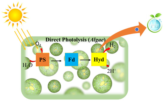
Figure 1.
Schematic representation of direct photolysis for hydrogen production.
In the direct process, the system follows the following reactions:
Although photoproduction of hydrogen in the biosystem is environmentally friendly and can be undertaken by partial activation of photosystem II in Chlamydomonas spp., it is not economically feasible because it is inefficient for development at the industrial level. When discussing the drawbacks of this mechanism, many physiological factors are taken into consideration, such as hydrogenase O2 sensitivity, competition with other metabolic pathways, downregulation of electron transport by non-dissipation of a proton gradient, and performance under non-saturating illumination [30].
2.2. Dark Fermentation
Dark fermentation (DF) is a process involving fermentation by dark-adapted microbes of carbohydrates under anoxic conditions to give H2 as a resulting product along with acids, as illustrated in Figure 2 [28]. Studies have shown that Clostridium spp. can use a wide variety of sugars, making it a possible candidate to form H2 from wastewater at a large scale [31]. The lowered pH due to acid output hampers the generation of H2.

Figure 2.
Diagrammatic representation of dark and photo fermentation (hybrid process).
A major economic emphasis is on biological H2 production from wastewater using dark fermentation. The H2 production system has many similarities with methanogenic anaerobic digestion, notably, the two gaseous compounds that can be separated from treated wastewater. The mixed microbial population present in both bioprocesses have the same properties but exhibit one major difference in biological H2 production: bacteria such as homo-acetogens and methanogens inhibit hydrogen formation. To destroy these microbes, heat treatment is required without affecting spore-forming fermenting bacteria. Other approaches include high dilution rates or low pH for higher activity of the reactor and optimized operating environmental conditions to maximize the output of hydrogen. Unfortunately, the production of bio-H2 depends on a comparatively limited volume of the overall equal H2 present in wastewater. We cannot estimate recovery efficiency in high-carbohydrate wastewater to surpass 15% of the electron equivalent, under optimized conditions. Therefore, various researchers have performed two-step processes that involve the development of bio-H2 via methanogenic anaerobic digestion to increase the overall energy output of the process. Methanogenic anaerobic digestion, as described later, is a useful and convenient process. Another promising technique is the conversion of methane to H2 via a catalytic method. Therefore, H2 production through the direct method is somewhat limited to the pretreatment step in large-scale energy production, while the discharge of H2 gas through plastic enclosures and thin metal sheets represents another limitation because of the high diffuse rate of H2 [32]. To increase the overall hydrogen yield, hybrid processes are also suggested, whereby organic acids produced in dark fermentation can be used as a feedstock in photo fermentation to produce hydrogen (Figure 2).
2.3. Photo Fermentation
The process of photo fermentation involves organic/inorganic substrate oxidation in the presence of O2 to release electrons that end up reducing ferredoxins. These reduced ferredoxins are related directly to the production of H2 and to the fixation of CO2. The following reaction takes place:
Although this process has advantages such as enhanced potential conversion yields and the ability to absorb a wide variety of substrates, there are drawbacks such as continuously regulated area/volume ratio maintenance in photobioreactors, temperature control, and controlled agitation. For the development of bio-H2 from wastewater, various types of reactor systems such as batch and continuous reactors are used, with each configuration providing its advantages and disadvantages [33].
3. Existing Wastewater Treatment Technologies and Their Bottlenecks
Traditional wastewater treatment usually takes place when wastewater is carried by a sewer to a centralized wastewater treatment plant, where the wastewater is then treated linearly by the end-of-pipe technology. It is time to make the switch to a closed-loop system [34], in which water is treated with simultaneous nutrient and energy recovery. Due to the superior positioning of decentralized wastewater treatment plants, centralized wastewater treatment plants can lead to a reduction in operational and capital expenditure (OPEX). Despite being in their infancy when it comes to deployment and optimization, decentralized solutions are lagging in the adoption phase when related to centralized ones. Clearly, the consequences of decentralization are visible, and developments in wastewater treatment plants are trying to make the transition from centralization to decentralization, where waste resources are reclaimed [35]. Because of a lack of effective methods for garbage disposal, management, and recycling, this problem will inevitably worsen [36]. Although centralized water systems are not relevant in many regions of the globe despite the drastic expansion in population and people favoring metropolitan areas, that trend is becoming even more prevalent as time progresses. For several reasons, from the changing demographics to building codes, rural people have to change their lifestyle, and this has placed wastewater setups under burden. Unfortunately, in several instances, this has led to efficient wastewater treatment systems not being put in place. In certain cases, it is difficult and expensive to build centralized wastewater treatment plants after the fact. With the increased use of distributed and non-networked technologies, it is more likely that we will develop a decentralized wastewater treatment infrastructure, which helps to encourage improved system robustness and lower economic and environmental costs [37].
Microbial Electrolysis Cell Mechanism for Wastewater Treatment with Simultaneous Hydrogen Production
The microbial electrolysis cell is a capable technique for removing organics while simultaneously producing hydrogen gas. When mixed with other elements, hydrogen is a plentiful element on Earth (water, hydrocarbons, etc.). To produce biohydrogen in a pure and regulated form, several industrial procedures are necessary. Among a variety of fuels (gasoline: 47.5 MJ·kg−1 higher heating value (HHV); 44.5 MJ·kg−1 lower heating value (LHV)), hydrogen has the greatest thermal efficiency (141.9 MJ·kg−1 HHV; 119.9 MJ·kg−1 LHV) and may be preserved for extended periods until being employed in fixed or mobile operations. The benefits of biohydrogen generation from waste matter, such as solid wastes and wastewater, are increased by making the process more sustainable [38]. Hydrogen is an excellent future fuel that can be used to meet the world’s energy demands due to its high energy density, ecologically benign combustion profile, and ability to be used at ambient temperature and pressure [39].
MECs provide a different approach for centralized wastewater treatment systems. According to this energy conversion estimate, the chemical energy potential of organic components constituting wastewater’s core is roughly 9.3-fold higher than the energy required to treat it [40]. There is a notable increase in employing biomass energy to get energy from biological anaerobic wastewater treatment because of the simplicity and resilience of this technique [41]. Anaerobic digestion (AD) is a technique that is increasingly being used to generate biogas from wastewater sludge. A process termed acetate digestion provides energy by breaking down acetate to produce CO2 and CH4 [42]. Alternatively, the process is quite sluggish and causes the biogas to produce a significant quantity of CO2, which reduces the energy density. Because biogas contains a high quantity of CO2, it must be stored, and substantial chemical treatment is performed, involving cryogenic separation, to eliminate CO2 until it can be utilized [43]. Compared to the use of biological techniques, MECs provide an alternate method for producing both CH4 and H2.
In MECs, microbes are utilized as biocatalysts to reduce the activation overpotential of a certain redox process, enhancing voltage efficiency and production rate [44]. On the surface of the anode, some microbes can develop a biofilm, which can convert the chemical energy contained in organic molecules into electrical energy. At the cathode, this electrical energy is subsequently used to produce additional useful products, such as H2 and CH4 [45]. To withstand cellular function and growth, certain microorganisms are electrochemically active, which means that they can transfer electrons along with the electrode to keep things running [46]. The chronological development of MEC technology is illustrated in Figure 3.
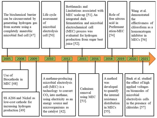
Figure 3.
Chronological development of microbial electrolysis cell (MEC) technology [42,47,48,49,50,51,52,53,54,55,56,57].
4. Thermodynamics and Electrochemistry for Hydrogen Production Using MEC
Because of the thermodynamic limitations, major organic compounds such as volatile acids (e.g., butyrate, acetate, and propionate) and solvents (e.g., ethanol and butanol) cannot be used for fermentative H2 production. However, additional energy is required for overcoming this limitation and for producing hydrogen [58]. In MEC, the required additional energy is provided by the voltage supplied through the power source. However, there is a necessity for higher applied potential than the equilibrium potential (Eeq) of the electrochemical cell (EC) for driving the MEC process. The equation is given as follows:
where Eeq is the equilibrium potential of the EC, Ecat is the cathodic half-life potential, and Ean is the anodic half-life potential.
Eeq = Ecat − Ean,
Therefore, to find the equilibrium voltage, determining the individual half-life potential using the Nernst equation is required.
Another well-researched electrochemical process is the hydrogen evolution reaction (HER). There are two reasons for this: (i) hydrogen evolution was originally regarded to be one of the simplest electrochemical processes, and (ii) it is a very significant process for society since hydrogen will one day replace fossil fuels as a transportation fuel, because of its simple reaction scheme.
The equilibrium potential of the hydrogen evolution process is significantly reliant on the pH at the cathode since protons (or hydroxyl ions) are involved, according to
It has been well established that HER proceeds via two successive steps. The initial adsorption of a proton to form adsorbed hydrogen, i.e., the Volmer reaction (H+ + e− + Had), is usually considered to be fast; however, there are two possibilities for the subsequent, slower hydrogen evolution process: one is the hemolytic Tafel reaction; the other is the heterolytic Heyrovsky reaction [59].
4.1. Anodic Potential for Hydrogen Production
In the MEC method, anode respiratory bacteria such as antibiotic-resistant bacteria (ARB) or exoelectrogens residing in anodic biofilms transform organic matter into bicarbonates, electrons, and protons; the electrons are then transported to the cathode via a limited energy supply (−0.300 V vs. standard hydrogen electrode (SHE) formed by ARB), where they interact with protons to produce hydrogen gas. For example, the sodium acetate reaction at the anode is presented below.
CH3COO− + 4H2O → 2HCO3− + 9H+ + 8e−.
In terms of the conceptual anode potential (Ean) for oxidation of acetates under typical biological conditions (pH = 7, T = 298.15 K, [CH3COO−] = 0.0169 mol·L−1 (1 g·L−1), and [HCO3−] = 0.005 mol·L−1), the Nernst equation can be approximated to
where Ean0 is the standard electrode potential for acetate oxidation (0.187 V), R is the universal gas constant (8.31 J·mol−1·K−1), T is the absolute temperature (K), and F is Faraday’s constant (9.65 × 10⁴ C·mol−1) [60].
4.2. Performance Calculation
4.2.1. Hydrogen Production Rate and Coulombic Efficiency
The system’s efficiency was measured in terms of the rate of hydrogen production, the rate of hydrogen recovery, the Coulombic efficiency, the volumetric density, and the energy recovered [61].
On the basis of COD elimination, the total potential number of moles generated, , is
where = 4 mol/mol denotes the maximum amount of hydrogen that can be stoichiometrically generated from the substrate, vL denotes the volume of liquid in the reactor, (g COD·L−1) denotes the change in concentration of the substrate during one batch cycle, and Ms denotes the molecular weight of the substrate. The COD concentration (g COD·L−1) was converted into moles of acetate using a conversion factor of 0.78 g COD·g−1 sodium acetate. According to the measured current, the moles of hydrogen recovered by can be calculated as follows:
where I = V/ is the current computed from the voltage across the resistor, and 2 is the conversion factor used to transform moles of electrons to hydrogen. = 96,485 C/mol e− is Faraday’s constant, and (s) is the interval over which data were collected. The Coulombic hydrogen recovery is expressed as
where is the Coulombic efficiency. The hydrogen recovery (in moles) at the cathode is calculated as
where is the number of moles of hydrogen recovered over a batch cycle. The maximum volumetric hydrogen production rate (Q) measured in m3 H2·m−3 of reactor per day (m3 H2·m−3·day−1) is calculated as
4.2.2. Energy Recovery
The amount of energy provided by the power source to the circuit (WE) is expressed as
where (V) denotes the voltage applied, is the external resistor, and (s) is the time increment for n data points measured during a batch cycle [61]. Energy balances based on combustion heats are usually used for electrolyzers and for predicting the amount of energy contained in organic matter. The amount of energy added by the substrate is expressed as
where = 870.28 kJ·mol−1 is the heat of combustion of the substrate, and denotes the total number of consumed moles of the substrate during a batch cycle based on COD removal. The ratio of the total energy of the hydrogen produced to the input of required electrical energy is the energy efficiency relative to the electrical input ().
where = 285.83 kJ·mol−1 is the energy content of hydrogen based on the heat of combustion (upper heating value), and = . The efficiency relative to the added substrate () is calculated as
The overall energy recovery based on both the electricity and the substrate inputs () is expressed as
The percentages of energy contributed by the power source () and substrate () are calculated as follows:
5. MEC Reactor Architecture
Similar to MFC, an elementary MEC architecture has two chambers that are connected employing an ion-exchange membrane. Over time, many different combinations of MECs, which are described below, have been developed for hydrogen yield improvement. The previous layouts comprised a basic H-type cell containing gas collection parts connected to a cathode chamber [62]. Eventually, various refinements were made to develop dual-chambered MECs for straightforward operation.
According to the findings of the research, based on a comparative analysis of various combinations, single-chambered MEC had higher hydrogen production rates and current densities than dual-chambered MEC. As a result, significant efforts have been made to further refine this combination for use in scale-up investigations. This surplus amount of MEC configurations indicates that the system setup for hydrogen generation in MEC is quite important. Substantial research was carried out to determine suitable MEC configurations. Several types of reactor modifications were assembled according to the results: cylindrical design, tubular reactor design, two-chamber MEC, up-flow single-chamber reactor, single-chamber membrane-less MEC, and many others. The hydrogen output and Coulombic efficiency of the MEC depend largely on the reactor configuration. Initially, researchers used dual-chambered MECs; the single-chambered MEC was introduced later for increasing the volumetric power density of the cathode and the hydrogen yield.
5.1. Single-Chambered MEC
A research group put together single-chambered MECs to synthesize hydrogen and assess the process efficiency. The main design used a glass bottle with a total capacity of 50 mL, while the secondary configuration used vials made of borosilicate glass with a total capacity of 10 mL; the cells usually used a mixed culture and pure culture of S. oneidensis, respectively. The anode and cathode, measuring 3.5 × 4 cm2 and 4 × 5 cm2, were kept 2 cm apart by plastic screws. The anode was type A carbon, and the cathode was type B carbon with platinum (0.5 mg·cm−2) as a catalyst separated by a J-cloth layer to prevent a short-circuit in both configurations [63,64]. Single-chambered MECs lack a membrane, as illustrated in Figure 4. When production rates are high, the microbial conversion of hydrogen to methane will be slow, with hydrogen being relatively insoluble in water. Energy losses of the membrane are lowered in membrane-less MECs, and the energy recovery process is high [65].
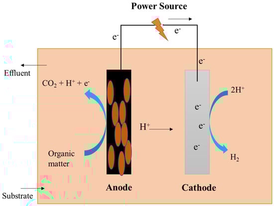
Figure 4.
Schematic representation of a single-chambered microbial electrolysis cell.
5.1.1. An Up-Flow Single-Chambered MEC
Lee HS constructed an up-flow single-chamber MEC by inserting a cathode on top of the MEC and implemented out a program to monitor hydrogen and electron equivalents in batch trials to enhance the output of hydrogen gas. In a batch evaluation experiment lasting 32 h with a starting acetate concentration of 10 mM, the CE was 60% ± 1%, the H2 yield was 59% ± 2%, and methane production was insignificant [66].
5.1.2. Smallest-Scale MEC
An MEC system with a single power source unit was designed. They used transparent glass serum vials with graphite plates functioning as anodes, which they found to be effective. It was soaked overnight, rinsed thrice in Milli-Q water, and further polished by sandpaper. Following the introduction of the unbent piece of wire through a hole drilled at the top center of the graphite plate, the bent end of the wire was inserted into a second hole and folded to form a tight connection between the wire and the plate. At 0.6 V of applied voltage, MECs having NiMo cathodes exhibited 33% better performance than NiW cathodes by accomplishing a hydrogen production rate (HPR) of 2.0 m3·day−1·m−3 at a current density of 270 A·m−3; however, this was slightly lower than MECs with a Pt catalyst which could accomplish 2.3 m3·day−1·m−3 [65].
5.1.3. A Cathode-on-Top Single-Chamber MEC
The reactor was made up of two parts: a top cover and the main chamber, both of which were constructed of glass and had a capacity of 0.4 L, as described in Figure 5 [62]. The substrate and electrolyte were pumped in via the bottom intake, and the produced gas was collected from the cathode with the use of a gasbag. HPR increased from 0.03 L·L−1·day−1 to 1.58 L·L−1·day−1 in a 24 h batch test when the applied voltage was expanded from 0.2 V to 1.0 V, and total hydrogen recoveries rose from 26.03% to 87.73% when the applied voltage was increased from 0.2 V to 1.0 V. The greatest total energy recovery was 86.78% at an applied voltage of 0.6 V [67].

Figure 5.
A cathode-on-top type of microbial dual-chambered reactor.
5.2. Dual-Chambered MEC
Dual-chambered MECs are often used in typical configurations and consist of an anodic and a cathodic chamber separated by the use of a membrane, as shown in Figure 6. The H-type MEC is a widely utilized dual-chambered MEC. Dual-chambered MECs are difficult to scale up because of their complex assemblies and large volumes with high internal resistance. The utilization of a membrane serves a dual purpose. It lowers the crossover from the anode to the cathode chamber and helps to prevent short-circuits at the cathode chamber, as well as aiding in the preservation of the purity of the product collected on the cathode side. The proton exchange membrane (PEM) is the most often used membrane since it is intended to only allow free protons to flow through while employing –SO3 functional groups [68,69]. Alternative membranes, including anion-exchange membranes (AEM), such as AMI7001, bipolar membranes, and charge-mosaic membranes (CMM) [70] have also been investigated in MECs, in addition to the conventional membranes [71]. Cheng and Logan created a reactor in which an anion-exchange membrane (AEM) was used between the electrodes to achieve their desired results. The anode chamber was filled with graphite granules that were heated with ammonia gas, which increased the current densities, resulting in a reduction in the amount of time required for reactor accommodation. A carbon cloth served as the cathode, and a platinum catalyst was maintained near the membrane, which was connected to the outside circuit via a titanium wire [72].
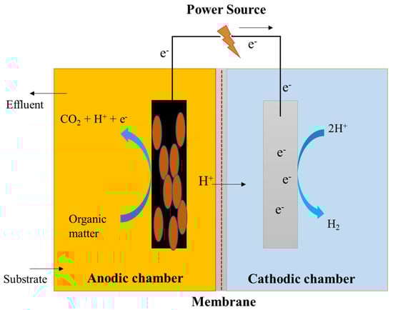
Figure 6.
Schematic representation of a dual-chambered microbial electrolysis cell.

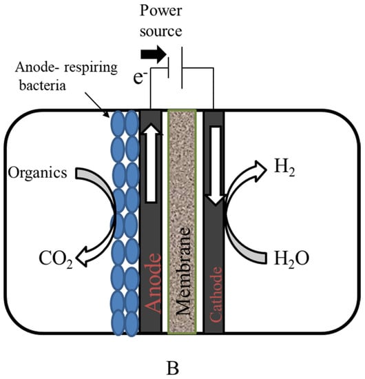
Figure 7.
(A) Top and front view of graphite brush anode used in the microbial electrolysis cell; (B) microbial electrolysis cell.

Table 1.
Patents associated with MEC reactor architecture.
Table 1.
Patents associated with MEC reactor architecture.
| Patent ID | Description | Reference |
|---|---|---|
| US8440438B2 | More competition for fossil fuels and the desire to avoid carbon dioxide release through burning necessitate the development of new and sustainable technologies for energy generation and carbon capture. In accordance with aspects of the present invention, methods are given that include providing an electromethanogenic reactor containing an anode, a cathode, and a plurality of methanogenic microorganisms positioned on the cathode. Methanogens are given electrons and carbon dioxide. Even in the absence of hydrogen and/or organic carbon sources, methanogenic microbes produce methane. | [73] |
| US20150233001A1 | Bioelectrochemical systems including a microbial fuel cell (MFC) and a microbial electrolysis cell (MEC) are provided. Both systems can ferment insoluble or soluble biomass, with the MFC capable of using a consolidated bioprocessing (CBP) organism to also hydrolyze an insoluble biomass and an electricigen to produce electricity. The MEC, on the other hand, relies on electricity input into the system, a fermentative organism, and an electricigen to produce fermentative products such as ethanol and 1,3-propanediol from a polyol biomass (e.g., containing glycerol). There are also approaches that are related. | [74] |
| EP2747181A1 | The present invention relates to a process for inhibiting methanogenesis in single-chamber microbial electrolysis cells, which includes the initial addition of at least one methanogenesis inhibitor and is characterized by the following: dissolved hydrogen is removed from said cells after said initial addition of at least one methanogenesis inhibitor. | [75] |
| US7922878B2 | The present invention provides a system for hydrogen gas generation that includes a hydrogen gas electrode assembly with a first anode in electrical communication with a first cathode, a microbial fuel cell electrode assembly with a second anode in electrical communication with a second cathode, a microbial fuel cell electrode assembly in electrical communication with a third cathode, and a hydrogen gas electrode assembly with a third anode in electrical communication with a third cathode. The hydrogen gas electrode assembly is at least partially contained in the interior space of a single-chamber housing. | [76] |
| US9216919B2 | A brush anode microbial electrolysis cell is shown. At the cathode of the microbial electrolysis cell, a method for manufacturing products such as hydrogen is also given. The microbial electrolysis cell has a cylindrical shape with a concentric brush anode spirally wrapped around the outside of a cylindrical MEC, as illustrated in Figure 7. In some situations, the procedure may require sparging the anode and/or cathode with air. In rare situations, CO2-containing gas can also be fed into a cathode chamber to lower the pH. | [77] |
| CN102408155A | The invention discloses a microbial electrolysis cell that combines CO2 conversion and sewage treatment functionalities. The invention relates to the intersection of biofuel cells and the environment, as well as carbon dioxide capture and usage, and it is specifically linked to a kind of CO2 conversion collection, with WWT in the microorganism electrolytic cell. | [78] |
6. Scale-Up Reactor Designing
Researchers have been trying to successfully construct large-scale reactors, so that wastewater treatment and value-added byproduct production become easier. These products can be hydrogen gas, methane, and so on. The theoretical conclusion for perfect up-scaling of the process through works of literature and data is difficult because of the differences in substrate type and other parameters such as operation mode [79]. Most of the reactors, as concluded from reviews, are operational in a continuously fed mode. The first scale-up of the MEC system was performed by Cusick et al. [80]. Based on the previous demonstration at laboratory scale, a single-chambered 1000 L MEC reactor was designed for H2 production from winery wastewater with high volatile fatty acid (VFA) content [81]. Along with hydrogen gas production, the production of methane was also observed at a gradually increasing level despite the MEC being functional for a short time. These observations, along with cases of cathode contamination, led to the development of a two-chamber system with a total capacity of 100 L by Heidrich [82,83]. In the tests conducted with wastewater produced domestically, methane production was inhibited successfully with the introduction of a polymeric membrane. This membrane separated the cathode from the rest of the reactor and helped in avoiding microbial crossover to the catholyte [79].
In batch mode, COD removal was high with higher H2 production. However, when the operational mode was switched to continuous mode, the COD level decreased along with the Coulombic efficiency. The probable reason behind the performance degradation may have been inefficient substrate flows into the reaction chamber and slow transportation of produced gas to the collection chamber. Hence, the usefulness of the transportation phenomenon in a functional scale-up reactor was highlighted [79]. Cotterill explained the cassette design module with Baeza using three different cassettes [84]. They observed material decay and degradation due to the applied voltage in a MEC. The development of a hermetic system is a challenge for reactors as the up-scaled reactors have shown leaking problems that might create balance errors. The existing systems are the perfect basis for up-scaled reactors; however, more work has to be done on the reactor design to make it fit for commercial and industrial applications [85,86,87]. More low-cost membranes and electrode materials need to be recognized. Attaining an optimum applied voltage and operational mode can also change the future of MECs [79]. Propylene has been the material chosen for building the body of a large-scale reactor [80,83], whereas polycarbonate is used for smaller systems [88]. Due to economic reasons, stainless-steel electrodes are used. Good electrolytic activity and proper H2 gas evolution add to its characteristics. However, nickel for the cathode and carbon materials for the anode [87] are also used.
7. Optimizing Features Affecting the MEC System Design for Hydrogen Production and Wastewater Treatment
Rapid commercialization of such a technique can result in a significant expansion in the industry, while also helping to enhance funds and boost research for continual advancements. The factors to be considered in the analysis and comparison of MECs for wastewater treatment and energy generation include several variables. This assessment highlights the main feedstock, anode and cathode materials, reactor volume, system architecture, outputs, and expenses as the most important aspects when it comes to the system design. These factors have an impact on system performance, as well as the commercialization of the technology’s economic feasibility. To be economically viable, MECs must strike a stability between overall system performance optimization and the economic proficiency of entirely basic components. MEC construction in the future should include ways to cut down on anode costs, enhance organic loading rates, and develop better knowledge about component requirements and electrode life expectancy [88]. For researchers to determine the next steps in the development of this technology, they must evaluate the parameters regarding industrial use and take into consideration the economic and manufacturing benefits, while simultaneously researching how to hasten the introduction of this method into the industry.
7.1. Feedstock
In general, wastewater strength is related to the degree of contamination of the water and determines the duration of treatment, reactor size, and quantity of energy needed and produced. This is because high-strength wastewater is rich in organic content; consequently, more energy may be recovered by treatment procedures. However, in the case of wastewater that has high strength, treating it will take a longer period, thereby increasing the amount of hydraulic retention time (HRT). An attempt should be made to enhance the HRT for a lower reactor size, thereby optimizing energy output or utilization. The loading levels and, hence, the organic loading rate (OLR) are substantially influenced by the source of wastewater.
With advancements in MEC cost, a system’s sustainable organic loading rate (OLR) varies within 800–1400 mg·L−1 [88]. As a result of the lower concentration of COD in urban wastewater (300–500 mg·L−1), it necessitates a smaller HRT (5–9 h); swine wastewater, on the other hand, requires a substantially longer HRT of 314 h due to the higher concentration of COD in the waste (18,300 mg·L−1). Longer HRTs provide a substantial obstacle to industrial adoption since they reduce the volume of waste which can be processed each day and necessitate the construction of larger reactors. High-strength wastewaters, on the other hand, offer more energy and, as a consequence, are more economically viable in terms of energy production, since larger organic loads have a higher energy potential. Moreover, wastewater of low strength has a low COD (total dissolved solidity (TDS) <250 mg·L−1), while the HRT is low; however, it is still difficult to economically justify treatment because of the extremely low energy output linked to its lower organic content. When wastewater strength (COD) increases even a little (by 360–400 mg·L−1), treatment is possible economically, since higher energy generation offsets the higher cost of treatment.
A hydrogen-producing MEC with an OLR ranging between 1000 and 2000 mg COD·L−1·day−1, according to Gil-Carrera et al., is a viable alternative when compared to activated sludge in terms of treatment efficacy. For wastewater treatments with OLRs more than 2000 mg COD·L−1·day−1, a possible HRT for diverse waste streams has been estimated [89]. The addition of electrodes, a wider bacterial adhesion surface, and the voltage delivered all contribute to enhanced performance. Based on the 1400 mg COD·L−1·day−1 OLR, both crude glycerol and cheese wheat, have extremely high HRT. In these circumstances, reactor design is critical to decreasing HRT while increasing solid retention to minimize reactor size. Traditional wastewater treatment requires a lot of energy, particularly activated sludge treatment, which accounts for approximately 60% of the total energy required. Compared to AD, MEC-ADs for the treatment of wastewater have led to a 1.7-fold increase in energy generation [90] and substrate removal, demonstrating the possibility for extremely effectual treatment for commercial waste streams previously employed. In addition, minimizing post-treatment needs would result in a significant reduction in the energy usage of the treatment procedure. The energy demands for full water treatment were estimated to be 0.057 kWh·m−3 (or 0.087 kWh·m−3 if ultraviolet treatment is chosen), which is about 85% less than the electrical energy consumption of a typical activated sludge process [91]. Utilizing MECs to reduce wastewater treatment energy consumption would have far-reaching global implications. There is an increase in the amount of research being done on the effectiveness of MECs in treating a variety of waste streams, which is aiding in the development of a better knowledge of how different microbial populations interact with different substrates. Because of its abundant availability and chemical composition, the waste feedstock is seen as an appealing and cost-effective substitute to pure chemicals in MECs.
7.1.1. Domestic or Residential Wastewater
The H2 produced by MECs is less expensive than the projected commercial value of hydrogen ($6·kg−1 H2), with a cost of $3.01·kg−1 H2 for domestic wastewater [92]. Heidrich et al. ran a 120 L MEC on site for the treatment of domestic wastewater. According to their findings, over more than 3 months, with a Coulombic efficiency of 55%, the MEC was capable of creating pure H2 (100% ± 6.4% purity). The reactor generated approximately 0.015 L H2·L−1·day−1 and retrieved around 70% of the electric power input [82,83]. According to Zhen et al. (2016), the utilization of the liquid portion of pressed municipal solid waste (LPW) for H2 production was investigated. The maximum H2 production (0.38 ± 0.09 m3·m−3·day−1 and 30.94 ± 7.03 mmol·g COD−1 added) was obtained at an applied voltage of 3.0 V and a pH of 5.5. Acetate, propionate, and butyrate, following their acetification, were used to achieve electrohydrogenesis, which resulted in an overall H2 recovery of 49.5% ± 11.3% of the COD provided in the experiment [93].
7.1.2. Industrial/Food Processing Wastewater
Montpart et al. investigated the usage of glycerol, milk, and starch in varied concentrations and levels of complexity in synthetic wastewater using a single-chamber MEC. It was discovered that only milk was capable of sustaining hydrogen synthesis for a prolonged period of time. The introduction of glycerol and starch in MEC did not inhibit the total multiplication of H2 scavengers, even under circumstances of short H2 retention time caused by frequent nitrogen sparging [94]. Shen et al. used a continuous up-flow fixed-bed MEC to treat recalcitrant wastewater generated from hydrothermal liquefaction of cornstalks while simultaneously producing hydrogen. At 1.0 V in the cathode, a hydrogen generation rate of 3.92 mL·L−1·day−1 was attained, although the highest power density (305.02 mW·m−3) was achieved at 0.6 V [95]. Guo et al. studied the effect of several cathode/anode ratios in membrane-less MECs using beer wastewater. With an improved cathode/anode ratio of 4 cm2·cm−3 and an applied voltage of 0.9 V, methane production of 0.14 m3·m−3·day−1 was achieved [95]. Furthermore, wastewater from a soybean edible oil refinery was used to generate bioelectricity and biomethane through the utilization of MFCs and MECs [89]. In comparison to conventional anaerobic digestion, the methane yield was 45.4 ± 1.1 L·kg−1 COD, and the generation rate of MECs was 0.133 ± 0.005 m3·m−3·day−1.
7.1.3. Fermentation Effluents
The fermentation effluents comprise various byproducts such as acetate, butyrate, ethanol, lactate, and formate. These byproducts can still undergo further reactions, resulting in the production of more hydrogen. The fermentation of sugars by bacteria is a common source of H2 production, although transformation of carbohydrates to hydrogen is insufficient. Additional hydrogen is frequently generated from the effluent of an ethanol dark fermentation reactor, according to the results of a single-chamber MEC test. At an applied voltage of E(ap) = 0.6 V, overall H2 recovery of 83% ± 4% was achieved using a pH-controlled effluent (pH = 6.7–7.0), with a hydrogen generation rate of 1.41 ± 0.08 m3 H2·m−3·day−1; furthermore, after combining the MEC and fermentation system, the overall H2 recovery increased to 96%, and the system was able to produce an average of 2.11 m3 H2·m−3·day−1, which corresponds to a voltage efficiency of 287%. At applied voltages ranging from 0.5 to 0.8 V, high cathodic hydrogen recoveries (ranging from 70% ± 5% to 94% ± 4%) were obtained [96].
When the MEC was integrated with the other fermentation system, 96% of the H2 was recovered at a production rate of 2.11 m3 H2·m−3·day−1, resulting in electrical energy productivity of 287%. Sosa-Hernández et al. investigated the potential of spent yeast (SY) for energy recovery in MEC. Tests were conducted on the concentrations of SY produced by bench alcoholic fermentation and ethanol, which ranged between 750 and 1500 mg COD·L−1 and between 0 and 2400 mg COD·L−1, respectively. The removal efficiency (RE), Coulombic recovery (CR), Coulombic efficiency (CE), H2 production, and current density of the COD removal system were all measured and analyzed. The combination of 1500 mg COD·L−1 SY + 1200 mg COD·L−1 ethanol produced an appealing current density (222.0 ± 31.3 A·m−3) and H2 generation (2.18 ± 0.66 LH2·d−1·LReactor−1) [97]. Cai et al. developed a bioelectrochemically assisted anaerobic reactor and compared it to an anaerobic digestion (AD) control reactor in order to generate methane. They achieved an average methane production rate of 0.070 mL CH4·mL−1 reactor·day−1, which was 2.59 times greater than the AD control reactor (0.027 m3 CH4·m−3·day−1), as well as an increase in COD removal of approximately 15% above the AD control. When the fermentation liquid is changed to sludge fermentation liquid, the rate of methane generation was raised even further, reaching 0.247 mL CH4·mL−1 reactor·day−1 [98].
7.1.4. Swine Wastewater
Employing a single-chamber MEC with a graphite-fiber brush anode, hydrogen gas was produced at a rate of 0.9–1.0 m3 H2·m−2·day−1 utilizing either pure or diluted swine wastewater (which may contain complex molecules that degrade at a slower rate than hydrogen). As a result, a greater allocation of carbon should be assured in order to meet the carbon demand that cannot be fulfilled by the organisms themselves. Undiluted swine waste matter would require a carbon-to-nitrogen ratio greater than 1.7 in order to degrade completely). COD removals ranged from 8–29% in 20 h tests and 69–75% in longer tests (184 h) that used full-strength effluent to achieve the highest levels of COD removal. The gas produced contained up to 77% ± 11% H2, with overall recoveries of up to 28% ± 6% of the COD contained within the waste matter being recovered as hydrogen [99].
7.1.5. Refinery Wastewater
Lijiao Ren was the first person to make use of refinery wastewaters [100]. The treatment of six different refinery wastewater samples was observed in mini-MECs. These waste matter samples were assessed separately and in combination with domestic waste matter as MFC feedstock to determine whether the treatability of the waste matter might be enhanced by introducing microbes and nutrients. In MEC testing, the various refinery wastewater collections differed in terms of current production and treatability. All the de-oiled wastewater samples from mixed sources performed well, with one sample providing values similar to DW. Other samples had low current densities as a result of high starting pH or a low BOD. The effectiveness of MECs was investigated using current generation throughout a number of batch-fed cycles. Refinery wastewater (RW) was treated in MECs that were previously acclimated utilizing domestic wastewater (DW) or a 50:50 mixture of RW and DW. The most effective results were obtained from de-oiled refinery wastewater collected from a single site (DOW1), which had a maximum current density of 2.1 ± 0.2 A·m−2 (maximum current density), 79% COD removal, and 82% BOD removal. The results observed were consistent with the results obtained from the domestic wastewater treatment study [100].
7.1.6. Winery Wastewater
Field site experiments were carried out at the Napa Wine Co. (NWC), which is located in Oakville, California, USA. NWC crushes and decants an annual total of 7000 tons of grapes and creates an annual total of 5.1 × 10⁴ m3 of wastewater. The treatment of on-site wastewater (through aerobic biological oxidation) consumes roughly 654,000 kWh of power per year. A continuous-flow MEC on a scale of 1000 L was built and analyzed for current production and COD removal using winery waste matter, with positive results. The reactor was divided into 24 modules, each containing 144 electrode pairs. The development of an exoelectrogenic biofilm took around 60 days, which is significantly lengthier than the time typically necessary for laboratory reactors. By the time the experiment was scheduled to be completed, current production attained a maximum of 7.4 A·m−3 (after 100 days). Despite the fact that the majority of the product gas was transformed to methane (86% ± 6%), the cathodic approach produced a peak of 0.19 ± 0.04 L·L−1·day−1. Higher techniques for isolating H2 gas generated at the cathode will be necessary in future testing in order to increase the amount of hydrogen recovered. The current generation was adjusted by guaranteeing a sufficient volatile fatty acid content (VFA/SCOD ≥ 0.5) and by increasing the temperature of the waste materials (to 31 ± 1 °C) in the waste stream. In addition, the usage of MECs remains a potential technology for the integration of energy recovery and wastewater treatment [101].
Various substrates have been utilized in MEC as illustrated in Table 2.
Table 2.
Performance of MEC configurations using different substrates.
7.2. Inoculation
Inoculating microorganisms into a MEC in which they would survive and grow, producing a microbial biofilm on the electrodes, is known as system inoculation. Because microorganisms are inoculated into the system, inoculum selection is essential for organic matter degradation [108]. Because the response of an MEC system is governed by the microorganisms involved, inoculation directly controls the start-up time of the system. The start-up period refers to the time it takes for a system to begin producing H2 or biogas. Long start-up durations diminish system proficiency because it takes longer for the system to begin generating energy; consequently, choosing the correct inoculum source is critical to maximizing system efficiency. Methods for reducing the time it takes for microbial electrochemical systems (MESs) to start up have been investigated. Selection of inoculum could be helpful to reduce start-up time while simultaneously improving efficiency. Biogas production was significantly increased by 18.5% when a mixture of inoculum sources containing a 1:4 ratio of activated sludge and municipal sewage was used as compared to a mono-inoculated treatment, implying that diversification is required for nutrient enrichment, which is essential for digestion [108]. In other words, the development of the methanogenic consortium in the system was also more rapid, which indicates that this mixed bacterial consortium helps enhance the hydrogenotrophic methanogen population. The amount of inoculum at the start of the experiment is equally critical. In the study conducted by Escapa et al., the authors discovered that the reactor failed to start when residential wastewater of low strength (230 mg COD·L−1) was used as the inoculum [51]. It is said that, with the addition of gas production, the start-up time for a large pilot system might be anywhere between 50 and 90 days. A simple technique to shorten the time it takes to set up a large-scale system is through “pre-acclimatization” of electrodes by applying a beneficial microbe to the electrodes before putting them into the system. Carbon electrodes that were inoculated with hydrogenotrophic bacteria extracted from natural bog sediment and pre-charged with hydrogen-rich water started up faster and produced more methane than those that were not [109].
A significant start-up time can also provide problems if repayment is not completed within a certain time frame. Pre-inoculation of electrodes can give a low-cost option for lowering start-up time, but this method comes with the added benefit of avoiding expensive modifications. Additional research into the best beginning circumstances will increase the technology’s appeal for industrial use, providing the basis for MECs to be commercialized for worldwide wastewater treatment.
7.3. Electrode Material
7.3.1. Anode Material
The anode’s performance is critical for bio-electrochemical systems that rely on bio-electrochemical reactions, which take place at the anode, and which can be replaced by MFCs, MECs, and MEC-ADs. It was established that anode activity is a restrictive component in the overall performance of the system [110]. As an electro-active bacterium (EAB) attaches itself to the bioanode surface, producing a biofilm, it provides the bioanode with energy. As a result of this oxidation by EAB, organic molecules are converted to CO2. Because of their remarkable ability to adhere to EAB, their huge surface area, and their abundance, carbon-based materials have become the most extensively used electrode material [111]. It has been shown that carbon compounds help to increase interfacial microbial colonization and, thus, the production of biofilms. Electrically conductive current collectors of metals are employed as electron acceptors, to overwhelm poor conductivity. Titanium wire is often utilized because of its corrosion resistance [40]. Additionally, the capability to simulate interfacial microbial colonies allows for improved current density by developing a beneficial microenvironment for electron transport that compensates for the decreased conductivity [112]. Graphite is affordable, plentiful, and conductive, and, because of this, it has become one of the most extensively used electrode materials [113]. Graphite electrodes have been implemented in many ways, including brush, granular, rods, felts, and foams [112]. Nevertheless, graphite’s molecular structure and morphology are both planar in comparison to other carbon materials due to its low surface porosity required for bacterial adhesion. Surface area-increasing porous 3D carbon materials, such as carbon brushes, felts, meshes, and foams, have been the focus of recent research [114]. Carbon fiber (CF) electrodes have previously proven to be effective and are currently being used to achieve good outcomes [115]. Carbon nanotubes (CNTs) have incredible electrical, mechanical, biological, and thermal properties, making them ideal for real-time applications. Despite extensive study and application possibilities of carbon nanotubes, many issues such as biodegradability, biotoxicity, and biosafety remain difficult to address and should be addressed with caution prior to design and manufacturing [116]. Anodes of a mesh-like design (i.e., porous, woven, or multilobed) tend to generate greater current densities (more current flows) than flat or plate-shaped anodes because of improved mass transfer, surface area, and biofilm growth. Carbon fiber brushes give excellent test results; however, because of their very expensive cost, they are seldom employed in large-scale BES. Based on an independent study, which used recycled carbon fiber anodes and found that, in comparison to graphite felt anodes, the use of recycled carbon fiber electrodes produced better results while also being cheaper, Carlotta-Janes et al. found that it was possible to improve performance while cutting costs if recycled carbon fiber anodes were used. As there is a considerable portion of the anode in the current model without a biofilm, increasing the surface area of the anode is more likely to result in a greater increase in biofilm density and adherence on the anode. Reduction in anode size will be advantageous for commercial viability since the anode material constitutes about 70% of the whole system, which will need a 90% drop in cost to make it profitable [88]. Additionally, molybdenum anodes showed excellent overall durability, neither corroding nor lowering in current production for over 350 days. Another important consideration is the endurance of the electrode materials. Unfortunately, there are no data on electrode materials’ long-term durability, and most experiments last about 1 year. Material dissipation in electrodes is often underestimated, which may lead to significant issues when determining which materials to utilize commercially. Stainless steel is also good since it has several characteristics which can be utilized [117]. In terms of conductivity and scale-up potential, stainless steel outperforms carbon anodes owing to lower capital expenditures, despite a relatively flat surface, which reduces its biocompatibility. Stainless steel has a high nickel concentration and may efficiently catalyze the HER. Stainless-steel brush cathodes, for example, produced hydrogen at a rate of 1.7 m3·m−3·day−1 and had a cathodic efficiency of 84%, comparable to Pt cathodes in single-chamber MECs. The high Ni content (8–11%) and the large specific surface area were also implicated for the rapid hydrogen generation (810 m2·m−3). Flame spray oxidation improves the biocompatibility of stainless steel by producing an iron oxide coating on the surface, which facilitates the adherence of iron-reducing bacteria and increases surface roughness without sacrificing corrosion resistance [118]. Because stainless steel has yet to be tested on pilot systems, more research into its durability is needed. Cotterill et al. compared a 30 L tank to a 175 L tank to examine how tank capacity influences H2 production. H2 generation was fourfold greater in the small MEC in comparison to the bigger MEC, when the anode surface area was reduced from 1 m2 to 0.06 m2. The larger MEC had a lesser performance, demonstrating a negative relationship between scale and gas output, implying that efficiency decreases as size increases [119]. As part of the commercialization process, a cost–benefit analysis of anode materials must be completed, which considers the material’s availability, corrosion resistance, and capacity to scale up.
7.3.2. Cathode Material
The necessity to create either CH4 or H2 dictates reactions at the cathode, and this is dependent on the need and potential to manufacture and utilize hydrogen or methane on-site. The rate at which H2 is consumed is determined by the amount of methanogenic activity present. The hydrogen will very probably be consumed throughout the reaction if the device is operated as a single chamber without a membrane, and the biogas generated will be in form of CH4 [80]. Temperature has a direct influence on methanogen activity, with temperatures exceeding 35 °C considerably boosting methanogenic activity [120]. Hydrogenotrophic methanogens are more prevalent in MECs where CH4 is produced, according to the study. Hydrogenotrophic methanogens produce CH4 through the intermediate synthesis of H2. The CH4 synthesis route reveals that the cathode material’s hydrogen evolution capacity is a critical design factor. As a result, the cathode serves as both a biocatalyst and an electrocatalyst, enhancing hydrogen evolution reactions (HER) by increasing electrode–microbe electron transfer [121]. The presence of hydrogen-scavenging bacteria in waste streams necessitates the use of membranes if pure hydrogen is required. Multiple investigations have shown that membrane systems can achieve hydrogen purity above 98% [122]. Corrosion resistance, good conductivity, high specific surface area, biocompatibility, and outstanding mechanical qualities are all required of successful cathode materials [123]. Furthermore, cathodic materials must minimize significant hydrogen evolution overpotentials. Cathode fabrication for industrial application must be low-cost, utilizing easily accessible materials and conventional production procedures, for the large-scale deployment to be practicable. Metals have been investigated because they conduct electricity more efficiently than carbon-based materials [124], and they have greater biocompatibility, as well as cathode potential, which prevents corrosion. Platinum has the strongest HER activity, which leads to improved H2 evolution [125]. Platinum, on the other hand, has some disadvantages, including being expensive and having substantial mining environmental effects; as a result, the invention of new metallic electrode materials is required [126]. Stainless steel and nickel have performed well as nonprecious metals [127].
Stainless steel is a typical material for electrode construction because it is a relatively inexpensive metal. When it comes to hydrogen production, stainless steel with a large specific surface area can be as effective as a platinum catalytic electrode containing carbon. Because of its high conductivity as a transient metal, stainless-steel mesh is thought to have outstanding ohmic resistance and electron transport resistance. Meshes and brushes made of stainless steel have a low cost and excellent performance, making them an ideal cathode made of a non-precious metal for further evaluation and scale-up operations. The findings are consistent with the use of meshes and wool in pilot-scale systems to produce a low-cost, high-surface-area cathode with a low cost and large surface area. Nickel, like other non-platinum metals, has high corrosion resistance, as well as high hermetic electron transfer activity. Nickel is also more corrosion-resistant than stainless steel, which is important for an electrode because it must be long-lasting in order to be commercially viable. Hydrogenotrophic methanogens play a role in the enhanced performance, implying that nickel’s high HER activity relative to other materials helps it perform better [128]. HER activity must be a key focus of study to maximize the efficiency of cathodes. Stainless steel is now commonly used. Due to its availability, a pilot study has shown it to be the ideal cathode material for scale-up. Cost and machinability are two factors to consider. On a pilot scale, a comparison was made between nickel and stainless steel. It would be wise to experiment with nickel cathodes to determine if the improved performance justifies the additional expense. Various cathode materials are described in Table 3.
7.4. Effect of Electrolyte pH
Because the HER at the cathode depends on electrolyte pH and has the most crucial impact on overall performance of MECs. High overpotentials can occur owing to a difference in redox potentials between anode and cathode chambers; it was observed that more cation instead of proton percolates through the cation-exchange membrane. Consequently, the cathode becomes alkaline while the anode becomes acidic. Theoretically, 59 mV of voltage loss is incurred due to a difference in pH level of 1 between the anode and cathode. Microbial activities are pH-dependent; microbes are highly sensitive to surrounding pH, and its variability may cause modifications in microbial respiration and, consequently, extracellular electron transfer. In fact, because microbes are mostly active at neutral pH, most MEC studies are conducted at pH 7. Moreover, many other parameters (ion transfer, conductivity, substrate oxidation, etc.) are directly or indirectly associated with pH. Researchers have reported that low cathode and high anode pH improved hydrogen production [129,130,131]. Protons accumulate under high pH, thereby increasing the electrogen proliferation due to conducive environment. Research suggests that periodic polarity reversal can be used to stabilize pH in two-chambered MECs [132]. An electrolyte, including a weak acid, operates as an electric charge at high pH, increasing MEC characteristics, and the deprotonation process may increase the conductivity of the electrolyte while lowering the impedance between the anode and cathode. However, we must evaluate the possible impacts of weak acid catalysis and solution resistance for a lower pH electrolyte to determine whether the reactor can function more effectively. However, certain experimental findings revealed that the presence of phosphate species and some weak electrolyte acids, as a charge carrier for improving conductivity, had a beneficial impact on a stainless-steel brush cathode and also reduced the Pt/C cathode’s overpotential. Merrill et al. [133] found that lowering the pH improves MEC performance by lowering solution resistance and cathode overpotential. Munoz et al. [134] found that using phosphate as an electrolyte may increase the rate of hydrogen generation and current density in MECs. Yossan et al. [135] investigated five kinds of catholytes in MECs, namely, deionized water, tap water, NaCl solution, acidified water, and a phosphate buffer. Due to its greater buffer capacity, a 100 mM phosphate catholyte in a MEC exhibited the best rate of hydrogen generation. As a result, phosphate is the most often utilized electrolyte in MECs.
7.5. Temperature
Temperature is a key element in MECs that affects their function because it improves exoelectrogen selectivity and production. Most microbes prefer an optimum temperature range of 35–40 °C for growth, enzyme activity, and the development of a durable biofilm, which increases substrate degradation, mass transfer, and power generation. According to the COD removal efficiency and microbe loading at the anode, Omidi et al. reported that 31 °C is the most efficient operating temperature for MECs [136]. As a result, the test temperature of an MEC is typically kept at about 30 °C. Lu et al., on the other hand, demonstrated that utilizing a single-chambered MEC produces hydrogen at low temperatures such as 4 °C, while simultaneously reducing the generation of methane [137]. Additionally, the anode biofilm and hydrodynamic force both impact hydrogen generation in MECs [138], with the hydrodynamic force having a larger effect on hydrogen production than the anode biofilm [139]. Furthermore, by placing two anodes on each side of the cathode, additional hydrogen may be generated.
7.6. Applied Potentials
As explained in the above sections, a minimum of 0.2 V is required to break the thermodynamic barrier for feasibly producing hydrogen at the MEC cathode. Large cathodic overpotentials reduce the efficiency of the overall process. Even though hydrogen evolution increases with increasing applied potential [140], optimum potential ranging from 0.2–0.8 V must be applied for achieving process scalability [141]. Researchers have reported that varying applied potential can decrease cell metabolism and increase cell lysis [142].
8. Bottlenecks in Commercialization of MECs for Biogas Production during Wastewater Treatment
It is essential to understand the functioning of MECs on a large scale for wastewater treatment. This also poses a barrier in adopting MECs owing to the little understanding of these systems. More modest frameworks produce high energy yield per volume when standardized. For metropolitan wastewater, the benchtop investigation produced standardized net energy of 25.96 kWh·m−3·day−1 [88]. On the other hand, a pilot-scale framework produced standardized net energy of 0.11 kWh·m−3·day−1. This demonstrates that energy creation cannot be accurately scaled, and that proficiency decreases as the size of the system increases. The net energy of a 1000 L pilot-scale framework with a cathodic surface area of 18.1 m2·m−3 was determined to be 2.11 kWh·m−3·day−1 for vineyard wastewater [80]. One obstruction is the trouble of precisely contrasting the various arrangements in the examination. The reactor size is just a single boundary and does not give a genuine portrayal of the framework’s versatility.
Table 3.
Different cathode materials along with catalysts used in MECs.
Table 3.
Different cathode materials along with catalysts used in MECs.
| Cathode Material | Catalyst | Id | Q (m3·m−3·day−1) | Eapp (v) | References |
|---|---|---|---|---|---|
| Activated carbon | Nitrogen | NA | 0.0060 (m3·m−2) | 0.8 kWh·m−3 | [143] |
| Stainless steel | Nickel oxide | NA | 0.76 | 0.6 kWh·m−3 | [49] |
| Molybdenum disulfide | 10.7 Am−2 | NA | NA | [144] | |
| Carbon cloth | Nickel/molybdenum | 2.1 Am−2 | 1.25 | 0.6 kWh·m−3 | [145] |
| Molybdenum disulfide/carbon nanotubes | NA | 0.01 | 0.8 kWh·m−3 | [146] | |
| Nickel powder | NA | 1.2 | 0.6 kWh·m−3 | [69] | |
| Nickel-tungsten | 200 Am−2 | 1.5 | [66] | ||
| Carbon paper | Nickel powder | NA | 2.6 (L·m−3·day) | 1.0 kWh·m−3 | [147] |
| Nano-Mg (OH)2/graphene | 18.3 Am−2 | 0.63 | 0.7 kWh·m−3 | [148] | |
| Palladium nanoparticles | NA | 2.6 | 0.6 kWh·m−3 | [149] | |
| Nickel foam | 22.8 Am−2 | 50 | 1.0 kWh·m−3 | [105] | |
| Nickel/phosphorous | NA | 2.29 | 0.9 kWh·m−3 | [150] | |
| Nickel/molybdenum | NA | 0.13 | 0.6 kWh·m−3 | [151] | |
| Nickel/tungsten | 0.14 | [152] | |||
| Graphene | NA | 1.31 | 0.8 kWh·m−3 | [153] | |
| Nickel/iron layered double hydroxide | 197 Am−2 | 2.12 | 0.8 kWh·m−3 | [154] | |
| Gas diffusion electrode | Nickel powder | 4.6 Am−2 | 5.4 | 1.0 kWh·m−3 | [155] |
8.1. Economic and Cost Analysis
The confirmation that innovation is financially viable for a large scope and has productivity that is virtually identical to or better than other arrangements accessible is critical to the passage of innovation from the lab to the field. Performing techno-economic and life-cycle assessments is important for progressing innovation used in the financial analysis of energy advancements to identify and evaluate operating and capital expenditures (OPEX and CAPEX) over their entire life cycle. The yield considers financial aid evaluators and levelized cost of energy objectives, such as investment return and net present value. To analyze the natural influence, the LCCA appraisal must be conducted similarly to the life-cycle assessment, with the same assumptions. MECs will benefit from using these projections since they will be better able to comprehend future costs, execution procedures, and risk factors [156]. When we say CAPEX, we are referring to the expenditure of performance; however, when we say OPEX, we are referring to the operational expense throughout the performance. Even though simple arrangements have a low CAPEX, they may be wasteful and require additional support, resulting in a higher OPEX than more complex arrangements. As a result, while evaluating the complete LCCA of innovations, it is necessary to consider both the CAPEX and the OPEX costs. Furthermore, when considering the profit from the venture from the energy produced, a high CAPEX might be acceptable in innovation such as MEC-AD for wastewater treatment, where energy is given [157].
In the ebb and flow UK market, 1 kWh of electrical expense is equivalent to £0.144, and, as a result, the price of treating 1 m3 of metropolitan wastewater is equivalent to £0.072 per kWh of electricity. As a result, for every 1 kg of COD neutralized, activated sludge treatment produces 0.4 kg of sludge, necessitating extra processing, which is often done using AD in order to recover a fraction of the energy [157]. MECs, on the other hand, can both reduce COD and generate energy. MECs currently require a significant amount of CAPEX to be implemented and are several times more costly (248-fold) than activated sludge frameworks [88].
According to the results of an analysis, the overall cost of the MEC framework was around £2344·m−3. In aspects of toxicity, MEC was evaluated by comparing to activated sludge. Although the MEC CAPEX was twice that of the active sludge, the consumption of energy was 10-fold lower [88]. Because of the potential for MECs to generate bioenergy, they can be either energy-neutral or energy-positive, whereas activated sludge is the most energy-concentrated of the currently available wastewater treatment techniques, according to the EPA [82,83]. Generally speaking, the expenses of MECs need to decrease by 84% to £375·m−3 [158].
The positive cash flows generated at 2020 pricing (£15,000·year−1) (Figure 8) had a small influence on the net present value (NPV) under scenario 1 (a doubling of current yields to 30 L·m−3) due to the cost of materials (assuming current performances). MEC capital expenses are projected to exceed their revenue from hydrogen production, as a result. For the baseline scenario (0) to be economically viable, either hydrogen prices must be raised to £5.09·kg−1 (higher than the EU’s target of £3.55 by 2020 and £2.66 by 2030) or yields must be increased from 15 L·m−3 to 21.5 L·m−3 by 2020 and 28.7 L·m−3 by 2030 (increases of 43% and 91%, respectively). Due to the relatively high cathodic efficiencies, it will be necessary to raise Coulombic efficiencies and the organic loading rate (OLR) in order to improve yields. Although hydrogen must be sold at a loss in order to be competitive with other sources of energy, power costs in MECs are negligible when compared to those of activated sludge (AS) [88].

Figure 8.
Cost–performance ratio curves for eight scenarios of a financially competitive MEC. Scenario 0: baseline MEC model; Scenario 1—double hydrogen yield; Scenario 2—applied voltage reduced to 0.6 V; Scenario 3—energy price changes; Scenario 4—anode and current collector value returned after 20 years; Scenario 5—membrane replaced annually; Scenario 6—membrane and cathode replaced annually; Scenario 7—additional staff member required; Limit 1—capital cost of reactor minus the anode; Limit 2—capital cost of reactor minus the anode and current collector (adapted from Aiken et al. [88]).
8.2. Scale-Up Strategies
An exploration was directed in which a pilot-scale MEC took care of winery wastewater utilizing different stacked modules and discovered that there was equivalent execution across every one of the 24 modules that were practically identical to the limited lab-scale test. It was tracked down that weak electric association among modules brought about considerable ohmic misfortunes, bringing about various flow densities among modules, featuring the need to utilize great arrangements among modules [80]. Although less expensive than utilizing large tanks, this methodology can be significantly more expensive than doing so because as many materials are needed to transport the numerous modules. This increases the CAPEX of the framework and serves as an obstacle to the commercialization of the product. Another examination distinguished that, while considering a piled strategy for the increase of hydrogen-generating MECs, the partition film between the anode and cathode poses a huge hindrance. The investigation tracked down that high internal resistance inside the cell is brought about by the sluggish development of electrons over the membrane layer. Moreover, because membranes are costly, using a large number of films could increase the cost of the framework, creating a significant barrier to commercialization. This shows that frameworks devoid of membranes might be effectively versatile.
The technique for arranging modest cells in series is equivalently less reported; numerous little vessels masterminded in series against one bigger tank implies that the framework can exploit improved blending, strong maintenance, diminished ohmic misfortunes, and enhanced microbial consortium separation over the treatment cycle. Large, permanent treatment vessels are frequently used in conventional wastewater treatment frameworks, and their treatment capacity is frequently restricted. Organizing reactor vessels in succession allows sediments to settle throughout the framework, reducing strong maintenance duration and developing microenvironments inside the framework based on the number of organics in each vessel [159]. A higher concentration of larger, undigested organics will typically be found in tanks toward the beginning of a series rather than tanks at the end of a series. Microbial colonies form in response to these specific conditions, just as they do in response to fluctuations in distributed oxygen, pH, volatile substances, and unsaturated fatty acids [160].
Pilot-Scale Limitations
MEC technology is at the technological readiness level (TRL) 5, which indicates that the system is being evaluated in a particular context. Instead of focusing solely on illustrating the result, future research should seek to standardize it. According to the literature study of the various pilot projects, there are two major areas where MECs must improve in order to become a viable wastewater treatment technology. It would be critical to achieve the target volumetric treatment rates at the beginning of this process in order to determine the feasibility of this strategy. Existing research suggests that increasing the rate at which organic materials are loaded into the system can improve this volumetric technique. This can be performed by either increasing the intensity of the wastewater or increasing the flow rate of the wastewater. Any of these modifications would increase the rate at which organics are distributed into the reactor within the wastewater, which in turn would increase the rate at which organics are removed from the wastewater. By fully appreciating and optimizing this mass transfer, it is able to design the optimal reactor length for the given flow rate while also accurately predicting the costs. Furthermore, the issue of scale is a significant concern [161]. The highest MEC recorded so far was 1000 L, achieved with a hydraulic retention time of 1 day. When it comes to wastewater treatment activities, it is far from the scale that is required. Therefore, several BESs have been built with compact electrodes, numerous units of which can be mounted in any established tank. This is crucial because it allows for treatment in urban environments with a small land footprint to be achieved with these current tanks because of their depth. The design of an electrode that can stretch to a depth of 3 m would have to take into account the influence of hydrostatic pressure on the development of the biofilm, the output, and the structural integrity of the electrode itself. It would, therefore, be necessary to cope with the advancements in the kinetic and thermodynamic features of biological and electrochemical mechanisms that have occurred throughout time. More research is required to investigate the most recent reactor designs that keep the same land footprint as existing properties, which is currently lacking [162].
8.3. Investigation of Methane and Hydrogen Generation and Its Implications for Industrial Application
Purified hydrogen can be utilized as an important asset for fuel and assembling different synthetic substances. Because hydrogen has a greater energy content than methane, it has the potential to improve the efficiency of hydrogen generation in comparison to methane. MECs for the evolution of hydrogen consist of a double-chamber reactor with a film placed at the cathode to prevent hydrogenotrophic methanogenesis from occurring, thereby improving the framework’s cost, and complications will only increase their expense and complexity [161]. In typical wastewaters, a rich source of microorganisms is present, rendering the cathode susceptible to biofouling, which could require replacement of the cathode, thus increasing the costs [88]. Hydrogen likewise requires modern storage spaces and handling hardware. On account of the on-site production of energy, the worth of methane and hydrogen will decrease to the levelized cost of energy (LCOE) and levelized cost of heat (LCOH) produced and used. There are broad foundations and equipment to preserve and change methane into electrical and nuclear power. A pilot-scale framework was developed to provide methane while also generating a significant amount of net energy [80]. In comparison, the standardized net energy announced for a hydrogen-delivery MEC was 76.2 kWh·m−3·day−1 at 98% purity, which is higher than the previous estimate [127].
The gas storage foundation additionally assumes a critical part in the business reasonability of utilizing MECs for energy production. It has been recommended that MECs can be combined with inexhaustible resources [162]. Renewable energy provides the MEC with the ability to generate gas, which can be used as a kind of energy storage. Compared to hydrogen, methane has a greater energy thickness when it comes to barometrical pressing factors. In addition to its increased energy thickness and greater atomic size, methane’s increased practicability makes it the most feasible candidate for non-compressed energy storage. Biogas generated by AD is of low quality and difficult to store, with storage energy accounting for only 10% of the total energy produced [163]. MEC-ADs generate biogas of good quality with CH4 content coming to 86% ± 6% [80], featuring the upside of MEC-ADs over AD frameworks with respect to energy storage capacity. MEC-ADs designed to generate methane can contend with AD innovation; however, this is generally neglected on a wide scale owing to expenses. In contrast to the generation of power from hydrogen, there are various innovations that can use biogas straightforwardly with responding motors, microturbines, energy units, gas turbines, steam turbines, and consolidated cycle frameworks. Moreover, biogas can be converted into biomethane, which can then be infused into the matrix [163]. Lastly, when compared to the development of methane storage and conversion innovation, the development of hydrogen storage and conversion innovation is less advanced.
Hydrogen Production Technology and Inventory
The production of hydrogen is primarily accomplished through two methods: steam methane reforming (SMR) of natural gas and electrolysis of water. Recently, there has been increased interest in hydrogen production from biomass resources. This is due to the large amount of biomass waste generated by various industrial and agricultural activities, which has the potential to be converted into useful energy in a very short period of time. A further interesting alternative for hydrogen production from renewable resources is high-temperature electrolysis (HTE) by solid oxide electrolysis cells (SOECs). These are the hydrogen production techniques that were investigated in this study, together with their inventories, which are summarized and provided in Table 4. In the literature, you can find a thorough overview of each of the different H2 technologies [164]. Although many key input parameters have been changed in this study, several of the underlying assumptions used in the analysis are still based on the default assumptions of the sub-models used for inventory data (the hydrogen production analysis models—H2A and the GREET model) and the Eco-invent. The emphasis of this study was on the unit-operational level, and, for the sake of simplicity, only the major unit (i.e., electrolyzer, industrial reformer, furnace) for each unit source was reconstructed utilizing generic data from the Eco-invent database for the manufacturing infrastructure. Because of the lack of data availability, several secondary systems were ruled out. It is widely acknowledged that such stages have minor consequences if they are spread out over the course of their operating lifespan [165]. Several different system configurations were simulated in order to test the sensitivity of the findings.
Table 4.
Resources required to produce 1 kg of H2 from different production technologies and pathways [166].
9. Integrated MEC Systems
MECs have been shown to be viable options for dealing with the issue of wastewater treatment while also producing hydrogen. However, there have been certain challenges in commercializing these MEC technologies. Thus, combining new technologies with traditional ones may be used to overcome the thermodynamic limits, as well as material prices, methanogens, substrate concentration, and other issues that MES faces on its own. The performance of several integrated systems is highlighted in Table 5. Various patents based on integrated MEC technology are described in Table 6.
Table 5.
Current integrated MEC configurations.
Table 6.
Various patents associated with integrated MEC technology.
10. Comparison between MEC Technology and Water Electrolysis
When compared to water electrolysis, the primary advantage of MECs is that they do not produce oxygen [181,182,183,184], which is regarded to be a part of the process safety; this process safety asset is essential when producing pressurized hydrogen, such as during water electrolysis, because, when producing pressurized hydrogen at high pressure, there is an increased risk of hydrogen crossover at the anode compartment [163]. A further advantage of MECs is that the anode produces chlorine at a very low potential, eliminating the need for the electrolyte to be dissociated from chlorine, which is required for water electrolysis. This is another advantage of MECs [185,186]. MECs have another operational parameter, which is pH. The pH of the electrolyte is neutral, although many microbial biofilms do not tolerate extremes in pH [183]. Furthermore, the neutral pH offers the additional process safety benefit of allowing electrolytes to be handled without the need for severe safeguards. When disposing of and replacing a phosphate buffer with neutral pH, it is much simpler than when disposing of and replacing pH 14 potassium hydroxide, which is used in water electrolysis [184,185,186].
Comparison in Terms of Theoretical Energy Yields
MECs are also more efficient than water electrolysis in terms of energy generation, and two different sources of energy must be considered, with electricity being the most prominent of the two. The reaction in MECs that produces hydrogen consumes a significantly lower amount of energy than water electrolysis, resulting in lower power consumption. It is an endothermic reaction that requires heat in order for the reaction to occur at equilibrium cell voltage. The energy yields from multichannel electrolysis cells (MECs) are up to 10–11.3 γG greater based on MEC configurations.
Chemical energy is the other source of energy, and it is obtained when the oxidation of various compounds present at the anode is completed. During the side production of methane, the energy yield for G, including hydrogen generation, decreased below 10; nevertheless, the thermal energy yield for both increased to 12 YH. This yield demonstrates that hydrogen produced by MECs can store up to 10 times the electrical energy in the form of Gibbs free energy [187]. Table 7 lists the characteristics of some of these pilot studies including electrical and thermal energy yields.
Table 7.
Characteristics of MEC pilot studies (volume, ionic conductivity, methane, and hydrogen production rates) with final electrical (γG) and thermal (γH) energy yields.
11. Conclusions
To summarize, the development of MEC technology has shown positive results, primarily by lowering the total cost of wastewater treatment and energy generation. Simultaneously, it delivers a significant advantage via the creation of value-added fuels such as hydrogen. Furthermore, MEC technology is still in its early stage, since it faces several obstacles such as mass transfer restrictions, energy loss, and other issues that must be thoroughly investigated on a pilot and industrial scale utilizing real-world wastewaters. However, when it comes to the actual applications of MEC technology, it should be noted that establishing unique configurations in both anode and cathode structural design, as well as membrane structural design, should be given top priority to maximize the technology’s cost-effectiveness. However, in recent years, reports have emerged that the technology’s prospects are promising, as seen by the successful construction of many pilot-scale MEC reactors, indicating that the first commercial encounter with the technology is on the way. There is a significant gap between the literature results and the reality of scalable research, and the real challenge today is now to study the credibility of pilot-scale studies. Moreover, there is no comparative analysis of the cost estimation with respect to conventional technologies and MEC, which could help in the commercialization. The obstacles to bringing this technology forward from TRL 5 are not only technological but are also connected to innovation policy incentives. The stringent regulatory efficiency restrictions and the profitability of water utilities do not support developments in systems that are unlikely to satisfy these standards immediately.
Biofuels and bioenergy are being developed using this approach, which has been proposed as a means of transforming electrical energy from renewable energy sources such as solar and wind into biofuels and bioenergy. As a result, the development of integrated MECs with hydrolysis has the potential to increase the rate of breakdown of nonbiodegradable complex organics and, as a result, improve the overall efficiency of production.
Author Contributions
Conceptualization, P.D. and P.S.; software, P.D.; validation, P.S., S.K., M.K., S.P., Y.-H.Y., and S.K.B.; writing—original draft preparation, P.D. and P.S.; writing—review and editing, P.S., D.J., and P.K.G.; supervision, P.S., S.K., S.P., and S.K.B. All authors read and agreed to the published version of the manuscript.
Funding
This study was supported by the Research Program to solve social issues of the National Research Foundation of Korea (NRF)s funded by the Ministry of Science and ICT (grant number 2021R1F1A1050325). This study was also performed with the support of the R&D Program of MOTIE/KEIT [grant number 20014350 and 20009508].
Institutional Review Board Statement
Not Applicable.
Informed Consent Statement
Not Applicable.
Acknowledgments
The authors would like to acknowledge the KU Research Professor Program of Konkuk University, Seoul, South Korea. The authors would like to acknowledge the Sharda University Seed grant for research, India.
Conflicts of Interest
The authors declare no conflict of interest.
References
- Baruah, J.; Nath, B.K.; Sharma, R.; Kumar, S.; Deka, R.C.; Baruah, D.C.; Kalita, E. Recent Trends in the Pretreatment of Lignocellulosic Biomass for Value-Added Products. Front. Energy Res 2018, 6, 141. [Google Scholar] [CrossRef]
- Savla, N.; Pandit, S.; Khanna, N.; Mathuriya, A.S.; Jung, S.P. Microbially Powered Electrochemical Systems Coupled with Membrane-Based Technology for Sustainable Desalination and Efficient Wastewater Treatment. J. Korean Soc. Environ. Eng. 2020, 42, 360–380. [Google Scholar] [CrossRef]
- Pandit, S.; Savla, N.; Jung, S.P. 16—Recent advancements in scaling up microbial fuel cells. In Integrated Microbial Fuel Cells for Wastewater Treatment; Abbassi, R., Yadav, A.K., Khan, F., Garaniya, V., Eds.; Butterworth-Heinemann: Oxford, UK, 2020; pp. 349–368. ISBN 978-0-12-817493-7. [Google Scholar]
- Singh Asiwal, R.; Kumar Sar, S.; Singh, S.; Sahu, M. Wastewater Treatment by Effluent Treatment Plants. IJCE 2016, 3, 19–24. [Google Scholar] [CrossRef] [Green Version]
- Dey, P.; Pal, P.; Kevin, J.D.; Das, D.B. Lignocellulosic Bioethanol Production: Prospects of Emerging Membrane Technologies to Improve the Process—A Critical Review. Rev. Chem. Eng. 2020, 36, 333–367. [Google Scholar] [CrossRef] [Green Version]
- Gude, V.G. Energy and Water Autarky of Wastewater Treatment and Power Generation Systems. Renew. Sustain. Energy Rev. 2015, 45, 52–68. [Google Scholar] [CrossRef]
- Bhatia, S.K.; Mehariya, S.; Bhatia, R.K.; Kumar, M.; Pugazhendhi, A.; Awasthi, M.K.; Atabani, A.E.; Kumar, G.; Kim, W.; Seo, S.-O.; et al. Wastewater Based Microalgal Biorefinery for Bioenergy Production: Progress and Challenges. Sci. Total Environ. 2021, 751, 141599. [Google Scholar] [CrossRef]
- Tiwari, R.R. Occupational Health Hazards in Sewage and Sanitary Workers. Indian J. Occup. Environ. Med. 2008, 12, 112–115. [Google Scholar] [CrossRef] [Green Version]
- Guimarães, N.R.; Filho, S.S.F.; Hespanhol, B.P.; Piveli, R.P. Evaluation of Chemical Sludge Production in Wastewater Treatment Processes. Desalin. Water Treat. 2016, 57, 16346–16352. [Google Scholar] [CrossRef]
- Sher, F.; Hanif, K.; Rafey, A.; Khalid, U.; Zafar, A.; Ameen, M.; Lima, E.C. Removal of Micropollutants from Municipal Wastewater Using Different Types of Activated Carbons. J. Environ. Manag. 2021, 278, 111302. [Google Scholar] [CrossRef]
- Agasam, T.; Savla, N.; Kalburge, S.J.; T.k., S.; Pandit, S.; Jadhav, D.A. Chapter 7—Microbial electrosynthesis: Carbon dioxide sequestration via bioelectrochemical system. In The Future of Effluent Treatment Plants; Shah, M., Rodriguez-Couto, S., Mehta, K., Eds.; Elsevier: Amsterdam, The Netherlands, 2021; pp. 113–132. ISBN 978-0-12-822956-9. [Google Scholar]
- Bhagchandanii, D.D.; Babu, R.P.; Sonawane, J.M.; Khanna, N.; Pandit, S.; Jadhav, D.A.; Khilari, S.; Prasad, R. A Comprehensive Understanding of Electro. Fermenta 2020, 6, 92. [Google Scholar] [CrossRef]
- Bhatia, S.K.; Jagtap, S.S.; Bedekar, A.A.; Bhatia, R.K.; Rajendran, K.; Pugazhendhi, A.; Rao, C.V.; Atabani, A.E.; Kumar, G.; Yang, Y.-H. Renewable Biohydrogen Production from Lignocellulosic Biomass Using Fermentation and Integration of Systems with Other Energy Generation Technologies. Sci. Total Environ. 2021, 765, 144429. [Google Scholar] [CrossRef]
- Rousseau, R.; Etcheverry, L.; Roubaud, E.; Basséguy, R.; Délia, M.-L.; Bergel, A. Microbial Electrolysis Cell (MEC): Strengths, Weaknesses and Research Needs from Electrochemical Engineering Standpoint. Appl. Energy 2020, 257, 113938. [Google Scholar] [CrossRef]
- Gaur, V.K.; Sharma, P.; Sirohi, R.; Awasthi, M.K.; Dussap, C.-G.; Pandey, A. Assessing the Impact of Industrial Waste on Environment and Mitigation Strategies: A Comprehensive Review. J. Hazard. Mater. 2020, 398, 123019. [Google Scholar] [CrossRef]
- Jin, B.; van Leeuwen, H.J.; Patel, B.; Yu, Q. Utilisation of Starch Processing Wastewater for Production of Microbial Biomass Protein and Fungal α-Amylase by Aspergillus Oryzae. Bioresour. Technol. 1998, 66, 201–206. [Google Scholar] [CrossRef]
- Kim, B.H.; Park, H.S.; Kim, H.J.; Kim, G.T.; Chang, I.S.; Lee, J.; Phung, N.T. Enrichment of Microbial Community Generating Electricity Using a Fuel-Cell-Type Electrochemical Cell. Appl. Microb. Biotechnol. 2004, 63, 672–681. [Google Scholar] [CrossRef]
- Vijayaraghavan, K.; Ahmad, D.; Lesa, R. Electrolytic Treatment of Beer Brewery Wastewater. Ind. Eng. Chem. Res. 2006, 45, 6854–6859. [Google Scholar] [CrossRef]
- Rezaei, F.; Richard, T.L.; Logan, B.E. Analysis of Chitin Particle Size on Maximum Power Generation, Power Longevity, and Coulombic Efficiency in Solid–Substrate Microbial Fuel Cells. J. Power Sources 2009, 192, 304–309. [Google Scholar] [CrossRef]
- Kjeldsen, P.; Barlaz, M.A.; Rooker, A.P.; Baun, A.; Ledin, A.; Christensen, T.H. Present and Long-Term Composition of MSW Landfill Leachate: A Review. Crit. Rev. Environ. Sci. Technol. 2002, 32, 297–336. [Google Scholar] [CrossRef]
- Habermann, W.; Pommer, E.H. Biological Fuel Cells with Sulphide Storage Capacity. Appl. Microbiol. Biotechnol. 1991, 35, 128–133. [Google Scholar] [CrossRef]
- Bustillo-Lecompte, C.F.; Mehrvar, M. Slaughterhouse Wastewater Characteristics, Treatment, and Management in the Meat Processing Industry: A Review on Trends and Advances. J. Environ. Manag. 2015, 161, 287–302. [Google Scholar] [CrossRef]
- Fornero, J.J.; Rosenbaum, M.; Angenent, L.T. Electric Power Generation from Municipal, Food, and Animal Wastewaters Using Microbial Fuel Cells. Electroanalysis 2010, 22, 832–843. [Google Scholar] [CrossRef]
- Venkata Mohan, S.; Saravanan, R.; Raghavulu, S.V.; Mohanakrishna, G.; Sarma, P.N. Bioelectricity Production from Wastewater Treatment in Dual Chambered Microbial Fuel Cell (MFC) Using Selectively Enriched Mixed Microflora: Effect of Catholyte. Bioresour. Technol. 2008, 99, 596–603. [Google Scholar] [CrossRef] [PubMed]
- Kumar, M.D.; Kavitha, S.; Tyagi, V.K.; Rajkumar, M.; Bhatia, S.K.; Kumar, G.; Banu, J.R. Macroalgae-Derived Biohydrogen Production: Biorefinery and Circular Bioeconomy. Biomass Conv. Bioref. 2021. [Google Scholar] [CrossRef]
- Staffell, I.; Scamman, D.; Abad, A.V.; Balcombe, P.; Dodds, P.E.; Ekins, P.; Shah, N.; Ward, K.R. The Role of Hydrogen and Fuel Cells in the Global Energy System. Energy Environ. Sci. 2019, 12, 463–491. [Google Scholar] [CrossRef] [Green Version]
- Cardeña, R.; Cercado, B.; Buitrón, G. Chapter 7—Microbial Electrolysis Cell for Biohydrogen Production. In Biohydrogen, 2nd ed.; Biomass, Biofuels, Biochemicals; Pandey, A., Mohan, S.V., Chang, J.-S., Hallenbeck, P.C., Larroche, C., Eds.; Elsevier: Amsterdam, The Netherlands, 2019; pp. 159–185. ISBN 978-0-444-64203-5. [Google Scholar]
- Nayak, B.K.; Pandit, S.; Das, D. Biohydrogen. In Air Pollution Prevention and Control; Kennes, C., Veiga, M.C., Eds.; John Wiley & Sons, Ltd: Chichester, UK, 2013; pp. 345–381. ISBN 978-1-118-52336-0. [Google Scholar]
- Rajesh Banu, J.; Ginni, G.; Kavitha, S.; Yukesh Kannah, R.; Adish Kumar, S.; Bhatia, S.K.; Kumar, G. Integrated Biorefinery Routes of Biohydrogen: Possible Utilization of Acidogenic Fermentative Effluent. Bioresour. Technol. 2021, 319, 124241. [Google Scholar] [CrossRef]
- Ghirardi, M.L.; King, P.W.; Mulder, D.W.; Eckert, C.; Dubini, A.; Maness, P.-C.; Yu, J. Hydrogen Production by Water Biophotolysis. In Microbial BioEnergy: Hydrogen Production; Advances in Photosynthesis and Respiration; Zannoni, D., De Philippis, R., Eds.; Springer: Dordrecht, The Netherlands, 2014; Volume 38, pp. 101–135. ISBN 978-94-017-8553-2. [Google Scholar]
- Savla, N.; Shinde, A.; Sonawane, K.; Mekuto, L.; Chowdhary, P.; Pandit, S. Microbial Hydrogen Production: Fundamentals to Application. In Microorganisms for Sustainable Environment and Health; Chowdhary, P., Raj, A., Verma, D., Akhter, Y., Eds.; Elsevier: Amsterdam, The Netherlands, 2020; pp. 343–365. ISBN 978-0-12-819001-2. [Google Scholar]
- Tang, J.H. A Review of Suitable Substrates for Hydrogen Production in Microbial Electrolysis Cells. IOP Conf. Ser. Earth Environ. Sci. 2021, 621, 012145. [Google Scholar] [CrossRef]
- Lin, C.-Y.; Lay, C.-H.; Sen, B.; Chu, C.-Y.; Kumar, G.; Chen, C.-C.; Chang, J.-S. Fermentative Hydrogen Production from Wastewaters: A Review and Prognosis. Int. J. Hydrog. Energy 2012, 37, 15632–15642. [Google Scholar] [CrossRef]
- Werner, C.M.; Katuri, K.P.; Hari, A.R.; Chen, W.; Lai, Z.; Logan, B.E.; Amy, G.L.; Saikaly, P.E. Graphene-Coated Hollow Fiber Membrane as the Cathode in Anaerobic Electrochemical Membrane Bioreactors—Effect of Configuration and Applied Voltage on Performance and Membrane Fouling. Environ. Sci. Technol. 2016, 50, 4439–4447. [Google Scholar] [CrossRef]
- Garrido-Baserba, M.; Vinardell, S.; Molinos-Senante, M.; Rosso, D.; Poch, M. The Economics of Wastewater Treatment Decentralization: A Techno-Economic Evaluation. Environ. Sci. Technol. 2018, 52, 8965–8976. [Google Scholar] [CrossRef]
- Rasheed, T.; Shafi, S.; Bilal, M.; Hussain, T.; Sher, F.; Rizwan, K. Surfactants-Based Remediation as an Effective Approach for Removal of Environmental Pollutants—A Review. J. Mol. Liq. 2020, 318, 113960. [Google Scholar] [CrossRef]
- Starkl, M.; Brunner, N.; Feil, M.; Hauser, A. Ensuring Sustainability of Non-Networked Sanitation Technologies: An Approach to Standardization. Environ. Sci. Technol. 2015, 49, 6411–6418. [Google Scholar] [CrossRef] [Green Version]
- Nikolaidis, P.; Poullikkas, A. A Comparative Overview of Hydrogen Production Processes. Renew. Sustain. Energy Rev. 2017, 67, 597–611. [Google Scholar] [CrossRef]
- Parkhey, P.; Gupta, P. Improvisations in Structural Features of Microbial Electrolytic Cell and Process Parameters of Electrohydrogenesis for Efficient Biohydrogen Production: A Review. Renew. Sustain. Energy Rev. 2017, 69, 1085–1099. [Google Scholar] [CrossRef]
- Kim, K.N.; Lee, S.H.; Kim, H.; Park, Y.H.; In, S.-I. Improved Microbial Electrolysis Cell Hydrogen Production by Hybridization with a TiO2 Nanotube Array Photoanode. Energies 2018, 11, 3184. [Google Scholar] [CrossRef] [Green Version]
- Escapa, A.; Mateos, R.; Martínez, E.J.; Blanes, J. Microbial Electrolysis Cells: An Emerging Technology for Wastewater Treatment and Energy Recovery. From Laboratory to Pilot Plant and Beyond. Renew. Sustain. Energy Rev. 2016, 55, 942–956. [Google Scholar] [CrossRef]
- Eerten-Jansen, M.C.A.A.V.; Heijne, A.T.; Buisman, C.J.N.; Hamelers, H.V.M. Microbial Electrolysis Cells for Production of Methane from CO2: Long-Term Performance and Perspectives. Int. J. Energy Res. 2012, 36, 809–819. [Google Scholar] [CrossRef] [Green Version]
- Awe, O.W.; Zhao, Y.; Nzihou, A.; Minh, D.P.; Lyczko, N. A Review of Biogas Utilisation, Purification and Upgrading Technologies. Waste Biomass Valor 2017, 8, 267–283. [Google Scholar] [CrossRef] [Green Version]
- Kitching, M.; Butler, R.; Marsili, E. Microbial Bioelectrosynthesis of Hydrogen: Current Challenges and Scale-Up. Enzyme Microb. Technol. 2017, 96, 1–13. [Google Scholar] [CrossRef]
- Pant, D.; Singh, A.; Bogaert, G.V.; Olsen, S.I.; Nigam, P.S.; Diels, L.; Vanbroekhoven, K. Bioelectrochemical Systems (BES) for Sustainable Energy Production and Product Recovery from Organic Wastes and Industrial Wastewaters. RSC Adv. 2012, 2, 1248–1263. [Google Scholar] [CrossRef]
- Sleutels, T.H.J.A.; Ter Heijne, A.; Buisman, C.J.N.; Hamelers, H.V.M. Bioelectrochemical Systems: An Outlook for Practical Applications. ChemSusChem 2012, 5, 1012–1019. [Google Scholar] [CrossRef]
- Liu, H.; Grot, S.; Logan, B.E. Electrochemically Assisted Microbial Production of Hydrogen from Acetate. Environ. Sci. Technol. 2005, 39, 4317–4320. [Google Scholar] [CrossRef] [PubMed]
- Rozendal, R.A.; Jeremiasse, A.W.; Hamelers, H.V.M.; Buisman, C.J.N. Hydrogen Production with a Microbial Biocathode. Environ. Sci. Technol. 2008, 42, 629–634. [Google Scholar] [CrossRef]
- Selembo, P.; Merrill, M.; Logan, B. The Use of Stainless Steel and Nickel Alloys as Low-Cost Cathodes in Microbial Electrolysis Cells. J. Power Sources 2009, 190, 271–278. [Google Scholar] [CrossRef]
- Foley, J.; Rozendal, R.; Hertle, C.; Lant, P.; Rabaey, K. Life Cycle Assessment of High-Rate Anaerobic Treatment, Microbial Fuel Cells, and Microbial Electrolysis Cells. Environ. Sci. Technol. 2010, 44, 3629–3637. [Google Scholar] [CrossRef]
- Escapa, A.; San-Martín, M.I.; Mateos, R.; Morán, A. Scaling-up of Membraneless Microbial Electrolysis Cells (MECs) for Domestic Wastewater Treatment: Bottlenecks and Limitations. Bioresour. Technol. 2015, 180, 72–78. [Google Scholar] [CrossRef]
- Dhar, B.R.; Elbeshbishy, E.; Hafez, H.; Lee, H.-S. Hydrogen Production from Sugar Beet Juice Using an Integrated Biohydrogen Process of Dark Fermentation and Microbial Electrolysis Cell. Bioresour. Technol. 2015, 198, 223–230. [Google Scholar] [CrossRef]
- Colantonio, N.; Kim, Y. Cadmium (II) Removal Mechanisms in Microbial Electrolysis Cells. J. Hazard. Mater. 2016, 311. [Google Scholar] [CrossRef]
- Liu, Z.; Zhou, A.; Zhang, J.; Wang, S.; Luan, Y.; Liu, W.; Wang, A.; Yue, X. Hydrogen Recovery from Waste Activated Sludge: Role of Free Nitrous Acid in a Prefermentation–Microbial Electrolysis Cells System. ACS Sustain. Chem. Eng. 2018, 6, 3870–3878. [Google Scholar] [CrossRef]
- Miller, A.; Singh, L.; Wang, L.; Liu, H. Linking Internal Resistance with Design and Operation Decisions in Microbial Electrolysis Cells. Environ. Int. 2019, 126, 611–618. [Google Scholar] [CrossRef]
- Wang, L.; Chen, Y.; Long, F.; Singh, L.; Trujillo, S.; Xiao, X.; Liu, H. Breaking the Loop: Tackling Homoacetogenesis by Chloroform to Halt Hydrogen Production-Consumption Loop in Single Chamber Microbial Electrolysis Cells. Chem. Eng. J. 2020, 389, 124436. [Google Scholar] [CrossRef]
- Baek, G.; Shi, L.; Rossi, R.; Logan, B.E. The Effect of High Applied Voltages on Bioanodes of Microbial Electrolysis Cells in the Presence of Chlorides. Chem. Eng. J. 2021, 405, 126742. [Google Scholar] [CrossRef]
- Guwy, A.J.; Dinsdale, R.M.; Kim, J.R.; Massanet-Nicolau, J.; Premier, G. Fermentative Biohydrogen Production Systems Integration. Bioresour. Technol. 2011, 102, 8534–8542. [Google Scholar] [CrossRef] [PubMed]
- Morales-Guio, C.G.; Stern, L.-A.; Hu, X. Nanostructured Hydrotreating Catalysts for Electrochemical Hydrogen Evolution. Chem. Soc. Rev. 2014, 43, 6555–6569. [Google Scholar] [CrossRef] [Green Version]
- Yasri, N.; Roberts, E.P.L.; Gunasekaran, S. The Electrochemical Perspective of Bioelectrocatalytic Activities in Microbial Electrolysis and Microbial Fuel Cells. Energy Rep. 2019, 5, 1116–1136. [Google Scholar] [CrossRef]
- Fetyan, A.; El-Nagar, G.A.; Lauermann, I.; Schnucklake, M.; Schneider, J.; Roth, C. Detrimental Role of Hydrogen Evolution and Its Temperature-Dependent Impact on the Performance of Vanadium Redox Flow Batteries. J. Energy Chem. 2019, 32, 57–62. [Google Scholar] [CrossRef] [Green Version]
- Kadier, A.; Simayi, Y.; Abdeshahian, P.; Azman, N.F.; Chandrasekhar, K.; Kalil, M.S. A Comprehensive Review of Microbial Electrolysis Cells (MEC) Reactor Designs and Configurations for Sustainable Hydrogen Gas Production. Alex. Eng. J. 2016, 55, 427–443. [Google Scholar] [CrossRef] [Green Version]
- Guo, K.; Tang, X.; Du, Z.; Li, H. Hydrogen Production from Acetate in a Cathode-on-Top Single-Chamber Microbial Electrolysis Cell with a Mipor Cathode. Biochem. Eng. J. 2010, 51, 48–52. [Google Scholar] [CrossRef]
- Hu, H.; Fan, Y.; Liu, H. Hydrogen Production Using Single-Chamber Membrane-Free Microbial Electrolysis Cells. Water Res. 2008, 42, 4172–4178. [Google Scholar] [CrossRef]
- Call, D.F.; Logan, B.E. A Method for High Throughput Bioelectrochemical Research Based on Small Scale Microbial Electrolysis Cells. Biosens. Bioelectron. 2011, 26, 4526–4531. [Google Scholar] [CrossRef] [PubMed]
- Hu, H.; Fan, Y.; Liu, H. Hydrogen Production in Single-Chamber Tubular Microbial Electrolysis Cells Using Non-Precious-Metal Catalysts. Int. J. Hydrog. Energy 2009, 34, 8535–8542. [Google Scholar] [CrossRef]
- Guo, X.; Liu, J.; Xiao, B. Bioelectrochemical Enhancement of Hydrogen and Methane Production from the Anaerobic Digestion of Sewage Sludge in Single-Chamber Membrane-Free Microbial Electrolysis Cells. Int. J. Hydrog. Energy 2013, 38, 1342–1347. [Google Scholar] [CrossRef]
- Rozendal, R.A.; Hamelers, H.V.M.; Buisman, C.J.N. Effects of Membrane Cation Transport on PH and Microbial Fuel Cell Performance. Environ. Sci. Technol. 2006, 40, 5206–5211. [Google Scholar] [CrossRef]
- Selembo, P.A.; Merrill, M.D.; Logan, B.E. Hydrogen Production with Nickel Powder Cathode Catalysts in Microbial Electrolysis Cells. Int. J. Hydrog. Energy 2010, 35, 428–437. [Google Scholar] [CrossRef]
- Rozendal, R.A.; Sleutels, T.H.J.A.; Hamelers, H.V.M.; Buisman, C.J.N. Effect of the Type of Ion Exchange Membrane on Performance, Ion Transport, and PH in Biocatalyzed Electrolysis of Wastewater. Water Sci. Technol. 2008, 57, 1757–1762. [Google Scholar] [CrossRef] [PubMed]
- Rozendal, R.A.; Hamelers, H.V.M.; Molenkamp, R.J.; Buisman, C.J.N. Performance of Single Chamber Biocatalyzed Electrolysis with Different Types of Ion Exchange Membranes. Water Res. 2007, 41, 1984–1994. [Google Scholar] [CrossRef]
- Kim, J.R.; Cheng, S.; Oh, S.-E.; Logan, B.E. Power Generation Using Different Cation, Anion, and Ultrafiltration Membranes in Microbial Fuel Cells. Environ. Sci. Technol. 2007, 41, 1004–1009. [Google Scholar] [CrossRef]
- Cheng, S.; Logan, B. Electromethanogenic Reactor and Processes for Methane Production 2013. Available online: https://patents.google.com/patent/US8440438/en?oq=microbial+electrolysis+cell (accessed on 28 June 2021).
- Reguera, G.; Speers, A.M.; Young, J.M.; Awate, B. Microbial Electrochemical Cells and Methods for Producing Electricity and Bioproducts Therein 2015. Available online: https://patents.google.com/patent/US20150233001/en?oq=microbial+electrolysis+cell (accessed on 28 June 2021).
- Baiget, S.G.; Fernández, M.L.V.; Cirucci, J.; Planell, N.M.; Sancho, F.J.L.; Labat, J.A.B.; Canudas, A.G. Process for the Methanogenesis Inhibition in Single Chamber Microbial Electrolysis Cells 2014. Available online: https://patents.google.com/patent/EP2747181A1/en?oq=EP2747181A1 (accessed on 29 June 2021).
- Logan, B. Electrohydrogenic Reactor for Hydrogen Gas Production 2011. Available online: https://patents.google.com/patent/US7922878B2/en?oq=US7922878B2 (accessed on 28 June 2021).
- Popat, S.; Parameswaran, P.; Torres, C.; Rittmann, B. Microbial Electrolysis Cells and Methods for the Production of Chemical Products 2015. Available online: https://patents.google.com/patent/US9216919B2/en?oq=US9216919B2 (accessed on 28 June 2021).
- 78. He, Y.; Wang, Y.; Xi, H.; Yao, S.; Wang, B. A Microbial Electrolytic Cell Integrating CO2 Conversion and Sewage Treatment 2012. Available online: https://patents.google.com/patent/CN102408155A/en?oq=CN102408155A (accessed on 28 June 2021).
- Rivera, I.; Schröder, U.; Patil, S.A. Chapter 5.8—Microbial Electrolysis for Biohydrogen Production: Technical Aspects and Scale-Up Experiences. In Microbial Electrochemical Technology; Biomass, Biofuels and Biochemicals; Mohan, S.V., Varjani, S., Pandey, A., Eds.; Elsevier: Amsterdam, The Netherlands, 2019; pp. 871–898. ISBN 978-0-444-64052-9. [Google Scholar]
- Cusick, R.D.; Bryan, B.; Parker, D.S.; Merrill, M.D.; Mehanna, M.; Kiely, P.D.; Liu, G.; Logan, B.E. Performance of a Pilot-Scale Continuous Flow Microbial Electrolysis Cell Fed Winery Wastewater. Appl. Microbiol. Biotechnol. 2011, 89, 2053–2063. [Google Scholar] [CrossRef] [PubMed]
- Call, D.; Logan, B.E. Hydrogen Production in a Single Chamber Microbial Electrolysis Cell Lacking a Membrane. Environ. Sci. Technol. 2008, 42, 3401–3406. [Google Scholar] [CrossRef] [PubMed]
- Heidrich, E.S.; Edwards, S.R.; Dolfing, J.; Cotterill, S.E.; Curtis, T.P. Performance of a Pilot Scale Microbial Electrolysis Cell Fed on Domestic Wastewater at Ambient Temperatures for a 12month Period. Bioresour. Technol. 2014, 173, 87–95. [Google Scholar] [CrossRef] [Green Version]
- Heidrich, E.S.; Dolfing, J.; Scott, K.; Edwards, S.R.; Jones, C.; Curtis, T.P. Production of Hydrogen from Domestic Wastewater in a Pilot-Scale Microbial Electrolysis Cell. Appl. Microbiol. Biotechnol. 2013, 97, 6979–6989. [Google Scholar] [CrossRef]
- Baeza, J.A.; Martínez-Miró, À.; Guerrero, J.; Ruiz, Y.; Guisasola, A. Bioelectrochemical Hydrogen Production from Urban Wastewater on a Pilot Scale. J. Power Sources 2017, 356, 500–509. [Google Scholar] [CrossRef]
- Carmona-Martínez, A.A.; Trably, E.; Milferstedt, K.; Lacroix, R.; Etcheverry, L.; Bernet, N. Long-Term Continuous Production of H2 in a Microbial Electrolysis Cell (MEC) Treating Saline Wastewater. Water Res. 2015, 81, 149–156. [Google Scholar] [CrossRef] [PubMed] [Green Version]
- Savla, N.; Khilari, S.; Pandit, S.; Jung, S.P. Effective Cathode Catalysts for Oxygen Reduction Reactions in Microbial Fuel Cell. In Bioelectrochemical Systems: Vol.1 Principles and Processes; Kumar, P., Kuppam, C., Eds.; Springer: Singapore, 2020; pp. 189–210. ISBN 9789811568725. [Google Scholar]
- Baudler, A.; Schmidt, I.; Langner, M.; Greiner, A.; Schröder, U. Does It Have to Be Carbon? Metal Anodes in Microbial Fuel Cells and Related Bioelectrochemical Systems. Energy Environ. Sci. 2015, 8, 2048–2055. [Google Scholar] [CrossRef] [Green Version]
- Aiken, D.C.; Curtis, T.P.; Heidrich, E.S. Avenues to the Financial Viability of Microbial Electrolysis Cells [MEC] for Domestic Wastewater Treatment and Hydrogen Production. Int. J. Hydrog. Energ. 2019, 44, 2426–2434. [Google Scholar] [CrossRef]
- Yu, Z.; Leng, X.; Zhao, S.; Ji, J.; Zhou, T.; Khan, A.; Kakde, A.; Liu, P.; Li, X. A Review on the Applications of Microbial Electrolysis Cells in Anaerobic Digestion. Bioresour. Technol. 2018, 255, 340–348. [Google Scholar] [CrossRef]
- Bo, T.; Zhu, X.; Zhang, L.; Tao, Y.; He, X.; Li, D.; Yan, Z. A New Upgraded Biogas Production Process: Coupling Microbial Electrolysis Cell and Anaerobic Digestion in Single-Chamber, Barrel-Shape Stainless Steel Reactor. Electrochem. Commun. 2014, 45, 67–70. [Google Scholar] [CrossRef]
- Gikas, P. Towards Energy Positive Wastewater Treatment Plants. J. Environ. Manag. 2017, 203, 621–629. [Google Scholar] [CrossRef]
- Cusick, R.D.; Kiely, P.D.; Logan, B.E. A Monetary Comparison of Energy Recovered from Microbial Fuel Cells and Microbial Electrolysis Cells Fed Winery or Domestic Wastewaters. Int. J. Hydrog. Energy 2010, 35, 8855–8861. [Google Scholar] [CrossRef]
- Zhen, G.; Kobayashi, T.; Lu, X.; Kumar, G.; Hu, Y.; Bakonyi, P.; Rózsenberszki, T.; Koók, L.; Nemestóthy, N.; Bélafi-Bakó, K.; et al. Recovery of Biohydrogen in a Single-Chamber Microbial Electrohydrogenesis Cell Using Liquid Fraction of Pressed Municipal Solid Waste (LPW) as Substrate. Int. J. Hydrog. Energy 2016, 41, 17896–17906. [Google Scholar] [CrossRef]
- Montpart, N.; Rago, L.; Baeza, J.A.; Guisasola, A. Hydrogen Production in Single Chamber Microbial Electrolysis Cells with Different Complex Substrates. Water Res. 2015, 68, 601–615. [Google Scholar] [CrossRef] [PubMed]
- Shen, R.; Liu, Z.; He, Y.; Zhang, Y.; Jianwen, L.; Zhu, Z.; Si, B.; Zhang, C.; Xing, X.-H. Microbial Electrolysis Cell to Treat Hydrothermal Liquefied Wastewater from Cornstalk and Recover Hydrogen: Degradation of Organic Compounds and Characterization of Microbial Community. Int. J. Hydrog. Energy 2016, 41, 4132–4142. [Google Scholar] [CrossRef]
- Bhatia, S.C. 23—Biohydrogen. In Advanced Renewable Energy Systems; Bhatia, S.C., Ed.; Woodhead Publishing India: New Delhi, India, 2014; pp. 627–644. ISBN 978-1-78242-269-3. [Google Scholar]
- Sosa-Hernández, O.; Popat, S.C.; Parameswaran, P.; Alemán-Nava, G.S.; Torres, C.I.; Buitrón, G.; Parra-Saldívar, R. Application of Microbial Electrolysis Cells to Treat Spent Yeast from an Alcoholic Fermentation. Bioresour. Technol. 2016, 200, 342–349. [Google Scholar] [CrossRef] [PubMed] [Green Version]
- Cai, W.; Han, T.; Guo, Z.; Varrone, C.; Wang, A.; Liu, W. Methane Production Enhancement by an Independent Cathode in Integrated Anaerobic Reactor with Microbial Electrolysis. Bioresour. Technol. 2016, 208, 13–18. [Google Scholar] [CrossRef] [PubMed] [Green Version]
- Lu, L.; Xing, D.; Xie, T.; Ren, N.-Q.; Logan, B. Hydrogen Production from Proteins via Electrohydrogenesis in Microbial Electrolysis Cells. Biosens. Bioelectron. 2010, 25, 2690–2695. [Google Scholar] [CrossRef]
- Ren, L.; Siegert, M.; Ivanov, I.; Pisciotta, J.M.; Logan, B.E. Treatability Studies on Different Refinery Wastewater Samples Using High-Throughput Microbial Electrolysis Cells (MECs). Bioresour. Technol. 2013, 136, 322–328. [Google Scholar] [CrossRef] [PubMed]
- Katuri, K.P.; Ali, M.; Saikaly, P.E. The Role of Microbial Electrolysis Cell in Urban Wastewater Treatment: Integration Options, Challenges, and Prospects. Curr. Opin. Biotechnol. 2019, 57, 101–110. [Google Scholar] [CrossRef]
- Rozendal, R.A.; Hamelers, H.V.M.; Euverink, G.J.W.; Metz, S.J.; Buisman, C.J.N. Principle and Perspectives of Hydrogen Production through Biocatalyzed Electrolysis. Int. J. Hydrog. Energy 2006, 31, 1632–1640. [Google Scholar] [CrossRef]
- Ditzig, J.; Liu, H.; Logan, B.E. Production of Hydrogen from Domestic Wastewater Using a Bioelectrochemically Assisted Microbial Reactor (BEAMR). Int. J. Hydrog. Energy 2007, 32, 2296–2304. [Google Scholar] [CrossRef]
- Cheng, S.; Logan, B.E. Ammonia Treatment of Carbon Cloth Anodes to Enhance Power Generation of Microbial Fuel Cells. Electrochem. Commun. 2007, 9, 492–496. [Google Scholar] [CrossRef]
- Jeremiasse, A.W.; Hamelers, H.V.M.; Saakes, M.; Buisman, C.J.N. Ni Foam Cathode Enables High Volumetric H2 Production in a Microbial Electrolysis Cell. Int. J. Hydrog. Energy 2010, 35, 12716–12723. [Google Scholar] [CrossRef]
- Zhen, G.; Lu, X.; Kobayashi, T.; Kumar, G.; Xu, K. Promoted Electromethanosynthesis in a Two-Chamber Microbial Electrolysis Cells (MECs) Containing a Hybrid Biocathode Covered with Graphite Felt (GF). Chem. Eng. J. 2016, 284, 1146–1155. [Google Scholar] [CrossRef]
- Krishnan, S.; Md Din, M.F.; Taib, S.M.; Nasrullah, M.; Sakinah, M.; Wahid, Z.A.; Kamyab, H.; Chelliapan, S.; Rezania, S.; Singh, L. Accelerated Two-Stage Bioprocess for Hydrogen and Methane Production from Palm Oil Mill Effluent Using Continuous Stirred Tank Reactor and Microbial Electrolysis Cell. J. Clean. Prod. 2019, 229, 84–93. [Google Scholar] [CrossRef]
- Achinas, S.; Euverink, G.J.W. Effect of Combined Inoculation on Biogas Production from Hardly Degradable Material. Energies 2019, 12, 217. [Google Scholar] [CrossRef] [Green Version]
- Xu, S.; Zhang, Y.; Luo, L.; Liu, H. Startup Performance of Microbial Electrolysis Cell Assisted Anaerobic Digester (MEC-AD) with Pre-Acclimated Activated Carbon. Bioresour. Technol. Rep. 2019, 5, 91–98. [Google Scholar] [CrossRef] [PubMed]
- Lim, S.S.; Yu, E.H.; Daud, W.R.W.; Kim, B.H.; Scott, K. Bioanode as a Limiting Factor to Biocathode Performance in Microbial Electrolysis Cells. Bioresour. Technol. 2017, 238, 313–324. [Google Scholar] [CrossRef]
- Savla, N.; Anand, R.; Pandit, S.; Prasad, R. Utilization of Nanomaterials as Anode Modifiers for Improving Microbial FuelCells Performance. J. Renew. Mater. 2020, 8, 1581–1605. [Google Scholar] [CrossRef]
- Li, S.; Cheng, C.; Thomas, A. Carbon-Based Microbial-Fuel-Cell Electrodes: From Conductive Supports to Active Catalysts. Adv. Mater. 2017, 29, 1602547. [Google Scholar] [CrossRef] [PubMed]
- Liu, D.; Roca-Puigros, M.; Geppert, F.; Caizán-Juanarena, L.; Na Ayudthaya, S.P.; Buisman, C.; ter Heijne, A. Granular Carbon-Based Electrodes as Cathodes in Methane-Producing Bioelectrochemical Systems. Front. Bioeng. Biotechnol. 2018, 6. [Google Scholar] [CrossRef] [Green Version]
- Guo, K.; Prévoteau, A.; Patil, S.A.; Rabaey, K. Engineering Electrodes for Microbial Electrocatalysis. Curr. Opin. Biotechnol. 2015, 33, 149–156. [Google Scholar] [CrossRef]
- Carlotta-Jones, D.I.; Purdy, K.; Kirwan, K.; Stratford, J.; Coles, S.R. Improved Hydrogen Gas Production in Microbial Electrolysis Cells Using Inexpensive Recycled Carbon Fibre Fabrics. Bioresour. Technol. 2020, 304, 122983. [Google Scholar] [CrossRef]
- Rasheed, T.; Hassan, A.A.; Kausar, F.; Sher, F.; Bilal, M.; Iqbal, H.M.N. Carbon Nanotubes Assisted Analytical Detection—Sensing/Delivery Cues for Environmental and Biomedical Monitoring. Trends Anal. Chem. 2020, 132, 116066. [Google Scholar] [CrossRef]
- Pocaznoi, D.; Calmet, A.; Etcheverry, L.; Erable, B.; Bergel, A. Stainless Steel Is a Promising Electrode Material for Anodes of Microbial Fuel Cells. Energy Environ. Sci. 2012, 5, 9645–9652. [Google Scholar] [CrossRef] [Green Version]
- Guo, K.; Donose, B.C.; Soeriyadi, A.H.; Prévoteau, A.; Patil, S.A.; Freguia, S.; Gooding, J.J.; Rabaey, K. Flame Oxidation of Stainless Steel Felt Enhances Anodic Biofilm Formation and Current Output in Bioelectrochemical Systems. Environ. Sci. Technol. 2014, 48, 7151–7156. [Google Scholar] [CrossRef] [PubMed]
- Cotterill, S.E.; Dolfing, J.; Jones, C.; Curtis, T.P.; Heidrich, E.S. Low Temperature Domestic Wastewater Treatment in a Microbial Electrolysis Cell with 1 M2 Anodes: Towards System Scale-Up. Fuel Cells 2017, 17, 584–592. [Google Scholar] [CrossRef] [Green Version]
- Ahn, Y.; Im, S.; Chung, J.-W. Optimizing the Operating Temperature for Microbial Electrolysis Cell Treating Sewage Sludge. Int. J. Hydrog. Energy 2017, 42, 27784–27791. [Google Scholar] [CrossRef]
- Zhang, T.; Nie, H.; Bain, T.S.; Lu, H.; Cui, M.; Snoeyenbos-West, O.L.; Franks, A.E.; Nevin, K.P.; Russell, T.P.; Lovley, D.R. Improved Cathode Materials for Microbial Electrosynthesis. Energy Environ. Sci. 2012, 6, 217–224. [Google Scholar] [CrossRef] [Green Version]
- Mohammed, A.J.; Ismail, Z.Z. Slaughterhouse Wastewater Biotreatment Associated with Bioelectricity Generation and Nitrogen Recovery in Hybrid System of Microbial Fuel Cell with Aerobic and Anoxic Bioreactors. Ecol. Eng. 2018, 125, 119–130. [Google Scholar] [CrossRef]
- Wang, L.; He, Z.; Guo, Z.; Sangeetha, T.; Yang, C.; Gao, L.; Wang, A.; Liu, W. Microbial Community Development on Different Cathode Metals in a Bioelectrolysis Enhanced Methane Production System. J. Power Sources 2019, 444, 227306. [Google Scholar] [CrossRef]
- Santoro, C.; Arbizzani, C.; Erable, B.; Ieropoulos, I. Microbial Fuel Cells: From Fundamentals to Applications. A Review. J. Power Sources 2017, 356, 225–244. [Google Scholar] [CrossRef]
- Sangeetha, T.; Guo, Z.; Liu, W.; Cui, M.; Yang, C.; Wang, L.; Wang, A. Cathode Material as an Influencing Factor on Beer Wastewater Treatment and Methane Production in a Novel Integrated Upflow Microbial Electrolysis Cell (Upflow-MEC). Int. J. Hydrog. Energy 2016, 41, 2189–2196. [Google Scholar] [CrossRef] [Green Version]
- Siegert, M.; Yates, M.D.; Spormann, A.M.; Logan, B.E. Methanobacterium Dominates Biocathodic Archaeal Communities in Methanogenic Microbial Electrolysis Cells. ACS Sustain. Chem. Eng. 2015, 3, 1668–1676. [Google Scholar] [CrossRef]
- San-Martín, M.I.; Sotres, A.; Alonso, R.M.; Díaz-Marcos, J.; Morán, A.; Escapa, A. Assessing Anodic Microbial Populations and Membrane Ageing in a Pilot Microbial Electrolysis Cell. Int. J. Hydrog. Energy 2019, 44, 17304–17315. [Google Scholar] [CrossRef]
- Siegert, M.; Yates, M.D.; Call, D.F.; Zhu, X.; Spormann, A.; Logan, B.E. Comparison of Nonprecious Metal Cathode Materials for Methane Production by Electromethanogenesis. ACS Sustain. Chem. Eng. 2014, 2, 910–917. [Google Scholar] [CrossRef] [PubMed] [Green Version]
- Ki, D.; Parameswaran, P.; Popat, S.C.; Rittmann, B.E.; Torres, C.I. Maximizing Coulombic Recovery and Solids Reduction from Primary Sludge by Controlling Retention Time and PH in a Flat-Plate Microbial Electrolysis Cell. Environ. Sci. Water Res. Technol. 2017, 3, 333–339. [Google Scholar] [CrossRef]
- Liu, W.; Huang, S.; Zhou, A.; Zhou, G.; Ren, N.; Wang, A.; Zhuang, G. Hydrogen Generation in Microbial Electrolysis Cell Feeding with Fermentation Liquid of Waste Activated Sludge. Int. J. Hydrog. Energy 2012, 37, 13859–13864. [Google Scholar] [CrossRef]
- Zhang, Y.; Angelidaki, I. Microbial Electrolysis Cells Turning to Be Versatile Technology: Recent Advances and Future Challenges. Water Res. 2014, 56, 11–25. [Google Scholar] [CrossRef]
- Borole, A.P.; Mielenz, J.R. Estimating Hydrogen Production Potential in Biorefineries Using Microbial Electrolysis Cell Technology. Int. J. Hydrog. Energy 2011, 36, 14787–14795. [Google Scholar] [CrossRef]
- Merrill, M.D.; Logan, B.E. Electrolyte Effects on Hydrogen Evolution and Solution Resistance in Microbial Electrolysis Cells. J. Power Sources 2009, 191, 203–208. [Google Scholar] [CrossRef]
- Munoz, L.D.; Erable, B.; Etcheverry, L.; Riess, J.; Basséguy, R.; Bergel, A. Combining Phosphate Species and Stainless Steel Cathode to Enhance Hydrogen Evolution in Microbial Electrolysis Cell (MEC). Electrochem. Commun. 2010, 12, 183–186. [Google Scholar] [CrossRef] [Green Version]
- Yossan, S.; Xiao, L.; Prasertsan, P.; He, Z. Hydrogen Production in Microbial Electrolysis Cells: Choice of Catholyte. Int. J. Hydrog. Energy 2013, 38, 9619–9624. [Google Scholar] [CrossRef]
- Omidi, H.; Sathasivan, A. Optimal Temperature for Microbes in an Acetate Fed Microbial Electrolysis Cell (MEC). Int. Biodeterior. Biodegrad. 2013, 85, 688–692. [Google Scholar] [CrossRef]
- Lu, L.; Ren, N.; Zhao, X.; Wang, H.; Wu, D.; Xing, D. Hydrogen Production, Methanogen Inhibition and Microbial Community Structures in Psychrophilic Single-Chamber Microbial Electrolysis Cells. Energy Environ. Sci. 2011, 4, 1329–1336. [Google Scholar] [CrossRef]
- Ajayi, F.F.; Kim, K.-Y.; Chae, K.-J.; Choi, M.-J.; Kim, I.S. Effect of Hydrodymamic Force and Prolonged Oxygen Exposure on the Performance of Anodic Biofilm in Microbial Electrolysis Cells. Int. J. Hydrog. Energy 2010, 35, 3206–3213. [Google Scholar] [CrossRef]
- Wang, A.; Liu, W.; Ren, N.; Cheng, H.; Lee, D.-J. Reduced Internal Resistance of Microbial Electrolysis Cell (MEC) as Factors of Configuration and Stuffing with Granular Activated Carbon. Int. J. Hydrog. Energy 2010, 35, 13488–13492. [Google Scholar] [CrossRef]
- Sun, M.; Sheng, G.-P.; Zhang, L.; Xia, C.-R.; Mu, Z.-X.; Liu, X.-W.; Wang, H.-L.; Yu, H.-Q.; Qi, R.; Yu, T.; et al. An MEC-MFC-Coupled System for Biohydrogen Production from Acetate. Environ. Sci. Technol. 2008, 42, 8095–8100. [Google Scholar] [CrossRef] [PubMed]
- Nam, J.-Y.; Tokash, J.C.; Logan, B.E. Comparison of Microbial Electrolysis Cells Operated with Added Voltage or by Setting the Anode Potential. Int. J. Hydrog. Energy 2011, 36, 10550–10556. [Google Scholar] [CrossRef]
- Chae, K.-J.; Choi, M.-J.; Kim, K.-Y.; Ajayi, F.F.; Chang, I.-S.; Kim, I.S. A Solar-Powered Microbial Electrolysis Cell with a Platinum Catalyst-Free Cathode To Produce Hydrogen. Environ. Sci. Technol. 2009, 43, 9525–9530. [Google Scholar] [CrossRef] [PubMed]
- Zhang, B.; Wen, Z.; Ci, S.; Chen, J.; He, Z. Nitrogen-Doped Activated Carbon as a Metal Free Catalyst for Hydrogen Production in Microbial Electrolysis Cells. RSC Adv. 2014, 4, 49161–49164. [Google Scholar] [CrossRef] [Green Version]
- Tokash, J.C.; Logan, B.E. Electrochemical Evaluation of Molybdenum Disulfide as a Catalyst for Hydrogen Evolution in Microbial Electrolysis Cells. Int. J. Hydrog. Energy 2011, 36, 9439–9445. [Google Scholar] [CrossRef]
- Hu, H.; Fan, Y.; Liu, H. Optimization of NiMo Catalyst for Hydrogen Production in Microbial Electrolysis Cells. Int. J. Hydrog. Energy 2010, 35, 3227–3233. [Google Scholar] [CrossRef]
- Yuan, H.; Li, J.; Yuan, C.; He, Z. Facile Synthesis of MoS2@CNT as an Effective Catalyst for Hydrogen Production in Microbial Electrolysis Cells. ChemElectroChem 2014, 1, 1828–1833. [Google Scholar] [CrossRef]
- Manuel, M.-F.; Neburchilov, V.; Wang, H.; Guiot, S.R.; Tartakovsky, B. Hydrogen Production in a Microbial Electrolysis Cell with Nickel-Based Gas Diffusion Cathodes. J. Power Sources 2010, 195, 5514–5519. [Google Scholar] [CrossRef] [Green Version]
- Dai, H.; Yang, H.; Liu, X.; Jian, X.; Liang, Z. Electrochemical Evaluation of Nano-Mg(OH)2/Graphene as a Catalyst for Hydrogen Evolution in Microbial Electrolysis Cell. Fuel 2016, 174, 251–256. [Google Scholar] [CrossRef]
- Huang, Y.-X.; Liu, X.-W.; Sun, X.-F.; Sheng, G.-P.; Zhang, Y.-Y.; Yan, G.-M.; Wang, S.-G.; Xu, A.-W.; Yu, H.-Q. A New Cathodic Electrode Deposit with Palladium Nanoparticles for Cost-Effective Hydrogen Production in a Microbial Electrolysis Cell. Int. J. Hydrog. Energy 2011, 36, 2773–2776. [Google Scholar] [CrossRef]
- Li, F.; Liu, W.; Sun, Y.; Ding, W.; Cheng, S. Enhancing Hydrogen Production with Ni–P Coated Nickel Foam as Cathode Catalyst in Single Chamber Microbial Electrolysis Cells. Int. J. Hydrog. Energy 2017, 42, 3641–3646. [Google Scholar] [CrossRef]
- Mitov, M.; Chorbadzhiyska, E.; Nalbandian, L.; Hubenova, Y. Nickel-Based Electrodeposits as Potential Cathode Catalysts for Hydrogen Production by Microbial Electrolysis. J. Power Sources 2017, 356, 467–472. [Google Scholar] [CrossRef]
- Wang, L.; Liu, W.; He, Z.; Guo, Z.; Zhou, A.; Wang, A. Cathodic Hydrogen Recovery and Methane Conversion Using Pt Coating 3D Nickel Foam Instead of Pt-Carbon Cloth in Microbial Electrolysis Cells. Int. J. Hydrog. Energy 2017, 42, 19604–19610. [Google Scholar] [CrossRef]
- Cai, W.; Liu, W.; Han, J.; Wang, A. Enhanced Hydrogen Production in Microbial Electrolysis Cell with 3D Self-Assembly Nickel Foam-Graphene Cathode. Biosens. Bioelectron. 2016, 80, 118–122. [Google Scholar] [CrossRef] [Green Version]
- Lu, L.; Hou, D.; Fang, Y.; Huang, Y.; Ren, Z.J. Nickel Based Catalysts for Highly Efficient H2 Evolution from Wastewater in Microbial Electrolysis Cells. Electrochim. Acta 2016, 206, 381–387. [Google Scholar] [CrossRef] [Green Version]
- Hrapovic, S.; Manuel, M.-F.; Luong, J.H.T.; Guiot, S.R.; Tartakovsky, B. Electrodeposition of Nickel Particles on a Gas Diffusion Cathode for Hydrogen Production in a Microbial Electrolysis Cell. Int. J. Hydrog. Energy 2010, 35, 7313–7320. [Google Scholar] [CrossRef] [Green Version]
- Savla, N.; Suman; Pandit, S.; Verma, J.P.; Awasthi, A.K.; Sana, S.S.; Prasad, R. Techno-Economical Evaluation and Life Cycle Assessment of Microbial Electrochemical Systems: A Review. Curr. Res. Green Sustain. Chem. 2021, 4, 100111. [Google Scholar] [CrossRef]
- Rabaey, K.; Verstraete, W. Bacterial Potential for Electricity Generation. Trends Biotechnol. 2005, 6, 291–298. [Google Scholar] [CrossRef]
- Escapa, A.; Gómez, X.; Tartakovsky, B.; Morán, A. Estimating Microbial Electrolysis Cell (MEC) Investment Costs in Wastewater Treatment Plants: Case Study. Int. J. Hydrog. Energy 2012, 37, 18641–18653. [Google Scholar] [CrossRef]
- Guo, H.; Kim, Y. Stacked Multi-Electrode Design of Microbial Electrolysis Cells for Rapid and Low-Sludge Treatment of Municipal Wastewater. Biotechnol. Biofuels 2019, 12, 23. [Google Scholar] [CrossRef]
- Wang, T.; Li, C.; Zhu, G. Performance, Process Kinetics and Functional Microbial Community of Biocatalyzed Electrolysis-Assisted Anaerobic Baffled Reactor Treating Carbohydrate-Containing Wastewater. RSC Adv. 2018, 8, 41150–41162. [Google Scholar] [CrossRef] [Green Version]
- Muoio, R.; Palli, L.; Ducci, I.; Coppini, E.; Bettazzi, E.; Daddi, D.; Fibbi, D.; Gori, R. Optimization of a Large Industrial Wastewater Treatment Plant Using a Modeling Approach: A Case Study. J. Environ. Manag. 2019, 249, 109436. [Google Scholar] [CrossRef]
- Wan, L.-L.; Li, X.-J.; Zang, G.-L.; Wang, X.; Zhang, Y.-Y.; Zhou, Q.-X. A Solar Assisted Microbial Electrolysis Cell for Hydrogen Production Driven by a Microbial Fuel Cell. RSC Adv. 2015, 5, 82276–82281. [Google Scholar] [CrossRef]
- Bastidas-Oyanedel, J.-R.; Schmidt, J.E. Increasing Profits in Food Waste Biorefinery—A Techno-Economic Analysis. Energies 2018, 11, 1551. [Google Scholar] [CrossRef] [Green Version]
- Lampert, D.J.; Cai, H.; Wang, Z.; Keisman, J.; Wu, M.; Han, J.; Dunn, J.; Sullivan, J.L.; Elgowainy, A.; Wang, M.; et al. Development of a Life Cycle Inventory of Water Consumption Associated with the Production of Transportation Fuels; Argonne National Lab. (ANL): Argonne, IL, USA, 2015. [Google Scholar]
- Bargigli, S.; Raugei, M.; Ulgiati, S. Comparison of Thermodynamic and Environmental Indexes of Natural Gas, Syngas and Hydrogen Production Processes. Energy 2004, 29, 2145–2159. [Google Scholar] [CrossRef]
- Mehmeti, A.; Angelis-Dimakis, A.; Arampatzis, G.; McPhail, S.J.; Ulgiati, S. Life Cycle Assessment and Water Footprint of Hydrogen Production Methods: From Conventional to Emerging Technologies. Environments 2018, 5, 24. [Google Scholar] [CrossRef] [Green Version]
- Beegle, J.R.; Borole, A.P. An Integrated Microbial Electrolysis-Anaerobic Digestion Process Combined with Pretreatment of Wastewater Solids to Improve Hydrogen Production. Environ. Sci. Water Res. Technol. 2017, 3, 1073–1085. [Google Scholar] [CrossRef]
- Hassanein, A.; Witarsa, F.; Lansing, S.; Qiu, L.; Liang, Y. Bio-Electrochemical Enhancement of Hydrogen and Methane Production in a Combined Anaerobic Digester (AD) and Microbial Electrolysis Cell (MEC) from Dairy Manure. Sustainability 2020, 12, 8491. [Google Scholar] [CrossRef]
- Huang, J.; Feng, H.; Huang, L.; Ying, X.; Shen, D.; Chen, T.; Shen, X.; Zhou, Y.; Xu, Y. Continuous Hydrogen Production from Food Waste by Anaerobic Digestion (AD) Coupled Single-Chamber Microbial Electrolysis Cell (MEC) under Negative Pressure. Waste Manag. 2020, 103, 61–66. [Google Scholar] [CrossRef]
- Lewis, A.J.; Ren, S.; Ye, X.; Kim, P.; Labbe, N.; Borole, A.P. Hydrogen Production from Switchgrass via an Integrated Pyrolysis–Microbial Electrolysis Process. Bioresour. Technol. 2015, 195, 231–241. [Google Scholar] [CrossRef] [Green Version]
- Li, X.-H.; Liang, D.-W.; Bai, Y.-X.; Fan, Y.-T.; Hou, H.-W. Enhanced H2 Production from Corn Stalk by Integrating Dark Fermentation and Single Chamber Microbial Electrolysis Cells with Double Anode Arrangement. Int. J. Hydrog. Energy 2014, 39, 8977–8982. [Google Scholar] [CrossRef]
- Marone, A.; Ayala-Campos, O.R.; Trably, E.; Carmona-Martínez, A.A.; Moscoviz, R.; Latrille, E.; Steyer, J.-P.; Alcaraz-Gonzalez, V.; Bernet, N. Coupling Dark Fermentation and Microbial Electrolysis to Enhance Bio-Hydrogen Production from Agro-Industrial Wastewaters and by-Products in a Bio-Refinery Framework. Int. J. Hydrog. Energy 2017, 42, 1609–1621. [Google Scholar] [CrossRef]
- Rivera, I.; Buitrón, G.; Bakonyi, P.; Nemestóthy, N.; Bélafi-Bakó, K. Hydrogen Production in a Microbial Electrolysis Cell Fed with a Dark Fermentation Effluent. J. Appl. Electrochem. 2015, 45, 1223–1229. [Google Scholar] [CrossRef]
- Khongkliang, P.; Kongjan, P.; Utarapichat, B.; Reungsang, A.; O-Thong, S. Continuous Hydrogen Production from Cassava Starch Processing Wastewater by Two-Stage Thermophilic Dark Fermentation and Microbial Electrolysis. Int. J. Hydrog. Energy 2017, 42, 27584–27592. [Google Scholar] [CrossRef]
- Wang, A.; Sun, D.; Cao, G.; Wang, H.; Ren, N.; Wu, W.-M.; Logan, B.E. Integrated Hydrogen Production Process from Cellulose by Combining Dark Fermentation, Microbial Fuel Cells, and a Microbial Electrolysis Cell. Bioresour. Technol. 2011, 102, 4137–4143. [Google Scholar] [CrossRef]
- Song, Y.-C.; Woo, W.-H. Anaerobic Digestion Apparatus Equipped with Landscape Bioelectrochemical Apparatus and Anaerobic Digestion Method of Organic Waste Using the Same 2015. Available online: https://patents.google.com/patent/KR101575790B1/en?oq=KR101575790B1 (accessed on 29 June 2021).
- Li, J.; Zhang, W. Experimental Device for Hydrogen Production by Electrolysis Assisted Fermentation 2010. Available online: https://patents.google.com/patent/CN201416000Y/en?oq=CN201416000Y (accessed on 29 June 2021).
- Jisheng, L.; Chao, S.; Li, X.; Haifeng, Z.; Bei, L.; Yu, G.; Shi, H.; Yichen, H.; Yang, L.; Haocheng, Y. Microbial Electrolytic Cell-Membrane Bioreactor Combined Treatment Device for Landfill Leachate 2020. Available online: https://patents.google.com/patent/CN211339214U/en?oq=CN211339214U (accessed on 29 June 2021).
- Krishnan, A. Power Management System for a Microbial Fuel Cell and Microbial Electrolysis Cell Coupled System 2014. Available online: https://patents.google.com/patent/US20140285007A1/en?oq=US20140285007A1 (accessed on 29 June 2021).
- Liang, Z.; Dai, H.; Zhao, Y.; Yang, H.; Liu, X. Microbial Fuel Cell Self-Driving Microbial Electrolytic Cell Hydrogen Production and Storage Method 2016. Available online: https://patents.google.com/patent/CN104141147B/en?q=MFC+%2b+MEC&oq=MFC+%2b+MEC (accessed on 29 June 2021).
- Chen, L.; Dong, X.; Wang, Y.; Xia, Y. Separating Hydrogen and Oxygen Evolution in Alkaline Water Electrolysis Using Nickel Hydroxide. Nat. Commun. 2016, 7, 11741. [Google Scholar] [CrossRef] [PubMed]
- Symes, M.D.; Cronin, L. Decoupling Hydrogen and Oxygen Evolution during Electrolytic Water Splitting Using an Electron-Coupled-Proton Buffer. Nat. Chem. 2013, 5, 403–409. [Google Scholar] [CrossRef]
- Dopson, M.; Ni, G.; Sleutels, T.H. Possibilities for Extremophilic Microorganisms in Microbial Electrochemical Systems. FEMS Microbiol. Rev. 2016, 40, 164–181. [Google Scholar] [CrossRef] [Green Version]
- Patil, S.A.; Harnisch, F.; Koch, C.; Hübschmann, T.; Fetzer, I.; Carmona-Martínez, A.A.; Müller, S.; Schröder, U. Electroactive Mixed Culture Derived Biofilms in Microbial Bioelectrochemical Systems: The Role of PH on Biofilm Formation, Performance and Composition. Bioresour. Technol. 2011, 102, 9683–9690. [Google Scholar] [CrossRef] [PubMed]
- Popat, S.C.; Torres, C.I. Critical Transport Rates That Limit the Performance of Microbial Electrochemistry Technologies. Bioresour. Technol. 2016, 215, 265–273. [Google Scholar] [CrossRef] [Green Version]
- Torres, C.I.; Marcus, A.K.; Rittmann, B.E. Proton Transport inside the Biofilm Limits Electrical Current Generation by Anode-Respiring Bacteria. Biotechnol. Bioeng. 2008, 100, 872–881. [Google Scholar] [CrossRef] [PubMed]
- Moscoviz, R.; Toledo-Alarcón, J.; Trably, E.; Bernet, N. Electro-Fermentation: How To Drive Fermentation Using Electrochemical Systems. Trends Biotechnol. 2016, 34, 856–865. [Google Scholar] [CrossRef]
- Sugnaux, M.; Happe, M.; Cachelin, C.P.; Gasperini, A.; Blatter, M.; Fischer, F. Cathode Deposits Favor Methane Generation in Microbial Electrolysis Cell. Chem. Eng. J. 2017, 324, 228–236. [Google Scholar] [CrossRef]
- Brown, R.K.; Harnisch, F.; Wirth, S.; Wahlandt, H.; Dockhorn, T.; Dichtl, N.; Schröder, U. Evaluating the Effects of Scaling up on the Performance of Bioelectrochemical Systems Using a Technical Scale Microbial Electrolysis Cell. Bioresour. Technol. 2014, 163, 206–213. [Google Scholar] [CrossRef]
- Luo, S.; Jain, A.; Aguilera, A.; He, Z. Effective Control of Biohythane Composition through Operational Strategies in an Innovative Microbial Electrolysis Cell. Appl. Energy 2017, 206, 879–886. [Google Scholar] [CrossRef]
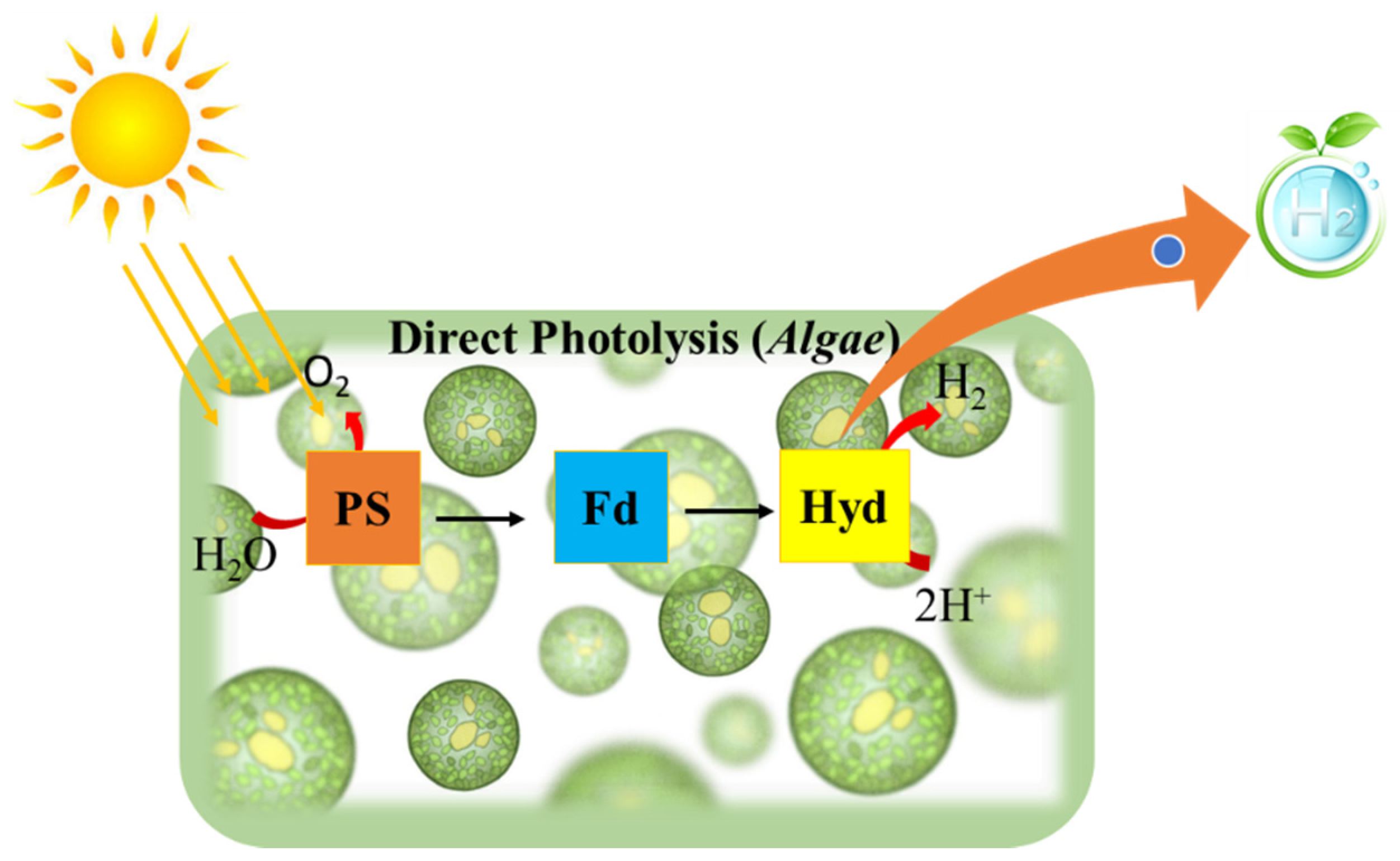
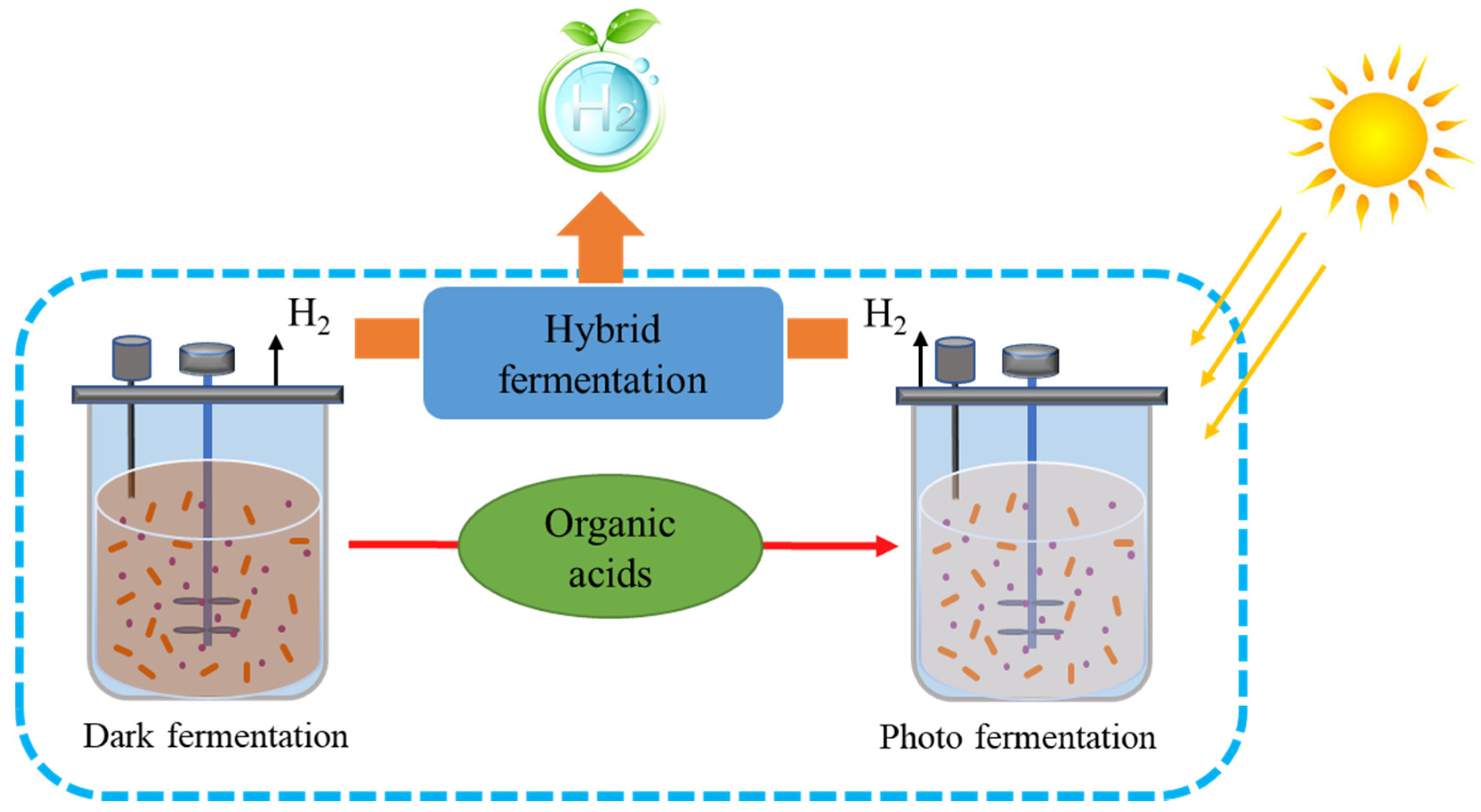
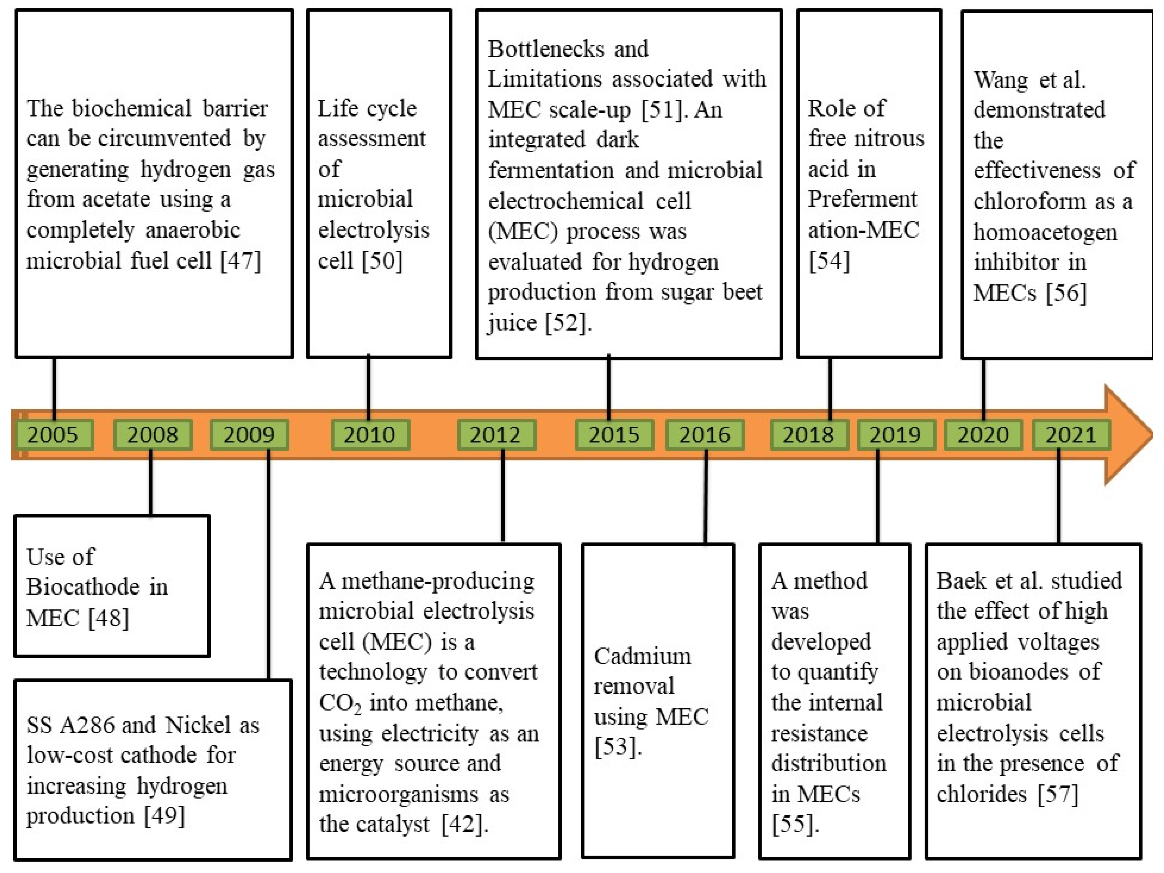

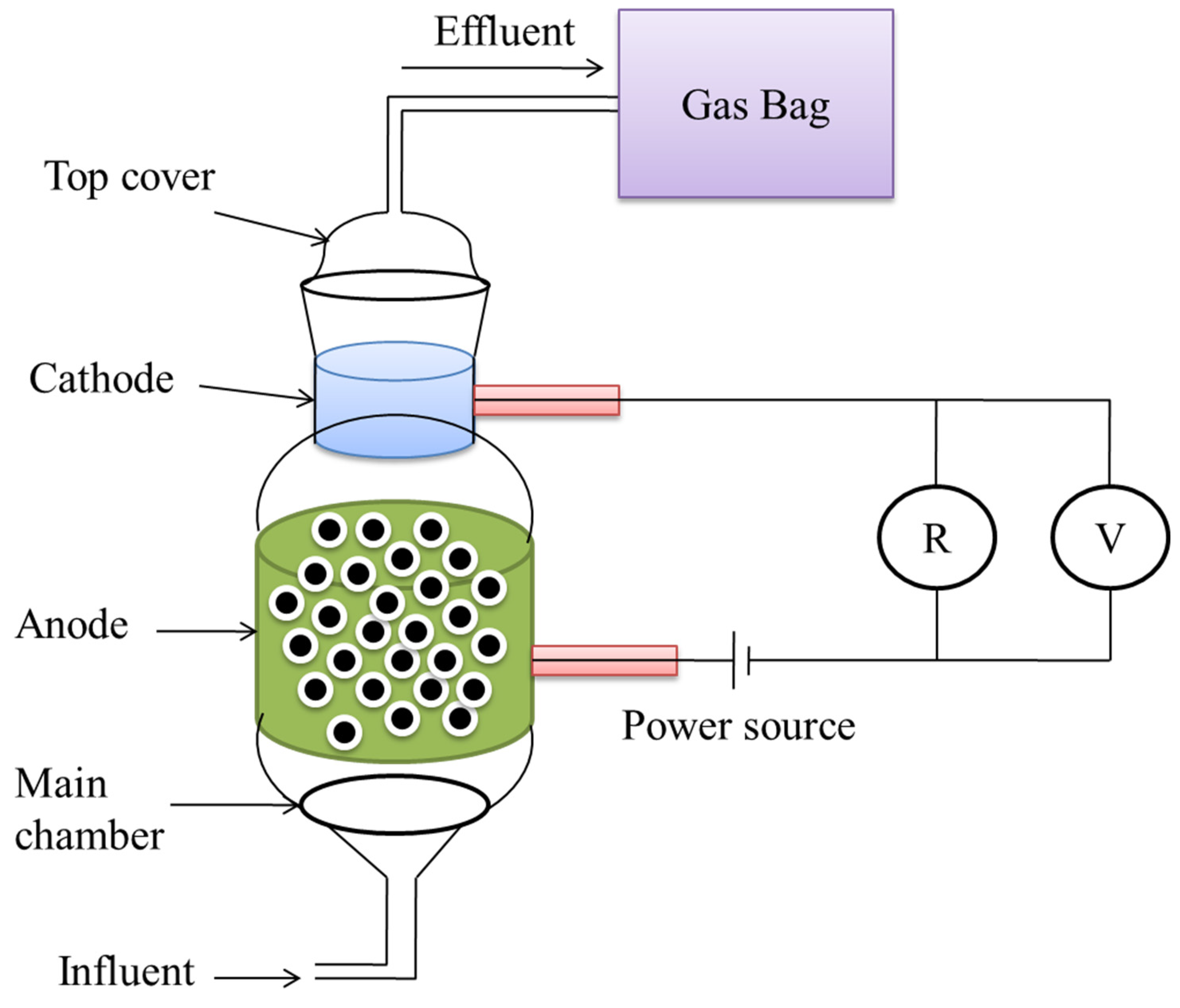

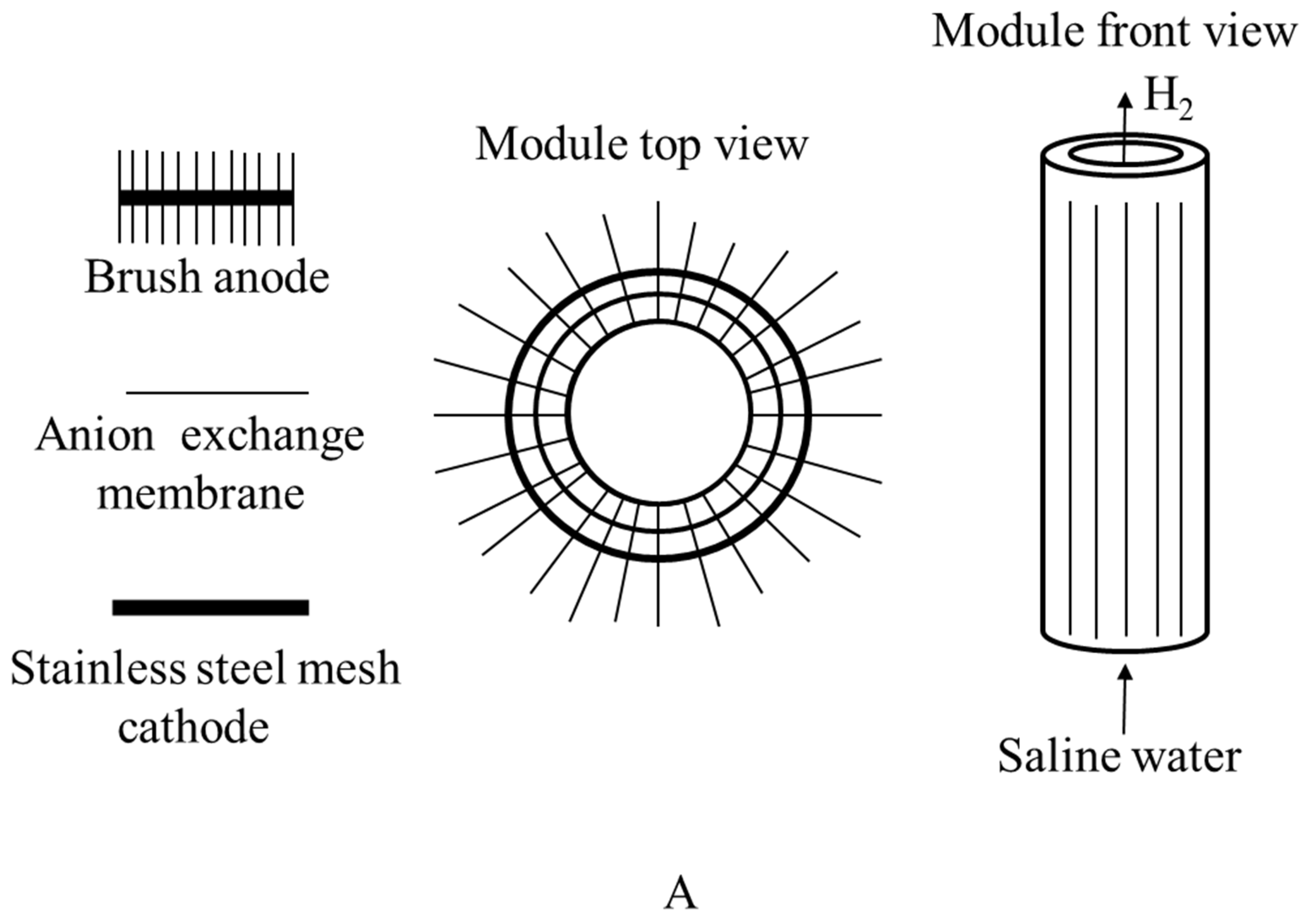

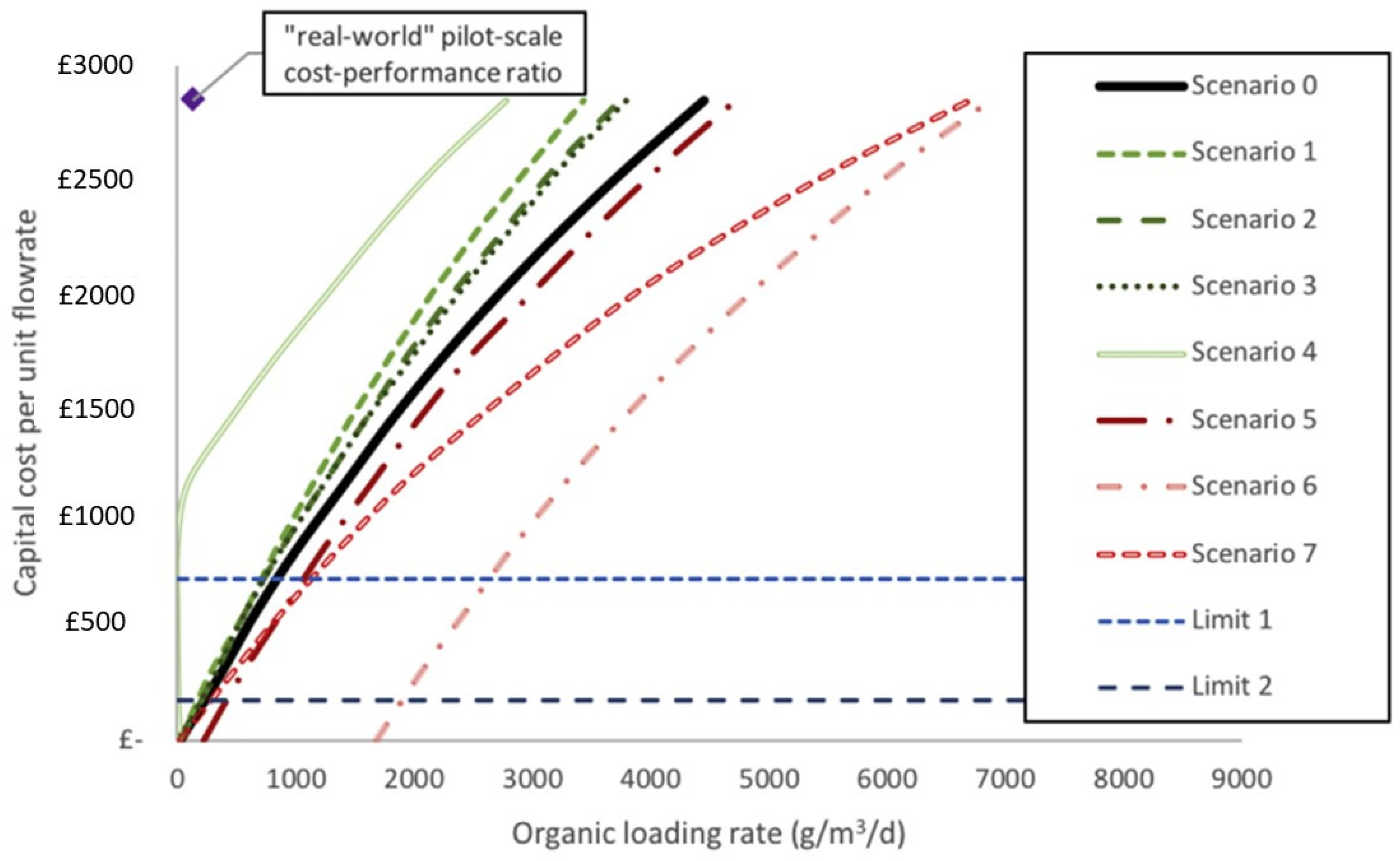
Publisher’s Note: MDPI stays neutral with regard to jurisdictional claims in published maps and institutional affiliations. |
© 2021 by the authors. Licensee MDPI, Basel, Switzerland. This article is an open access article distributed under the terms and conditions of the Creative Commons Attribution (CC BY) license (https://creativecommons.org/licenses/by/4.0/).