Review

Deployable Membrane-Based Energy Technologies: the Ethiopian Prospect

by
Abreham Tesfaye Besha
1,*,
Misgina Tilahun Tsehaye
2,
Girum Ayalneh Tiruye
3,
Abaynesh Yihdego Gebreyohannes
4,
Aymere Awoke
5 and
Ramato Ashu Tufa
6,*
1
Department of Chemistry, College of Natural and Computational Science, Jigjiga University, P.O. Box 1020 Jigjiga, Ethiopia
2
University Grenoble Alpes, University Savoie Mont Blanc, CNRS, Grenoble INP, LEPMI, 38 000 Grenoble, France
3
Materials Science Program/Department of Chemistry, Addis Ababa University, P. O. Box 1176 Addis Ababa, Ethiopia
4
Advanced Membranes and Porous Materials Center (AMPM), King Abdullah University of Science and Technology (KAUST), Thuwal 23955–6900, Saudi Arabia
5
Biological and Environmental Science and Engineering Division (BESE), Red Sea Research Center, King Abdullah University of Science and Technology (KAUST), Thuwal 23955–6900, Saudi Arabia
6
Department of Energy Conversion and Storage, Technical University of Denmark, Building 310,2800 Kgs. Lyngby, Denmark
*
Authors to whom correspondence should be addressed.
Sustainability 2020, 12(21), 8792; https://doi.org/10.3390/su12218792
Submission received: 4 October 2020 / Revised: 18 October 2020 / Accepted: 20 October 2020 / Published: 22 October 2020

Abstract

:
Membrane-based energy technologies are presently gaining huge interest due to the fundamental engineering and potentially broad range of applications, with economic advantages over some of the competing technologies. Herein, we assess the potential deployability of the existing and emerging membrane-based energy technologies (MEnT) in Ethiopia. First, the status of the current energy technologies is provided along with the active energy and environmental policies to shape the necessary research strategies for technology planning and implementation. Ethiopia is a landlocked country, which limits the effective extraction of energy, for instance, from seawater using alternative, clean technologies such as reverse electrodialysis and pressure retarded osmosis. However, there exists an excess off-grid solar power (up to 5 MW) and wind which can be used to drive water electrolyzers for hydrogen production. Hydrogen is a versatile energy carrier that, for instance, can be used in fuel cells providing zero-emission solutions for transport and mobility. Although Ethiopia is not among the largest CO2 emitters, with more than 90% energy supply obtained from waste and biomass, the economic and industrial growth still calls for alternative CO2 capture and use technologies, which are highlighted in this work. We believe that the present work provides (i) the status and potential for the implementation of MEnT in Ethiopia (ii) and basic guidance for researchers exploring new energy pathways toward sustainable development in developing countries.

1. Introduction

Energy is one of the most important needs of human beings and plays a vital role in the socioeconomic development in general. The energy demand is increasing from time to time mainly due to economic growth, increasing population as well as increasing living standards. The international energy administration (EIA) projected that the world energy consumption would grow by 50% between 2018 and 2050 [1]. Non-renewable energy sources (mainly fossil fuels—natural gas, coal and oil) make up more than 81% of the energy consumption, the most common form of energy being oil covers 31.6% [2]. The Ethiopian energy sources is mainly depending on biomass for household purposes. Its coverage is more than 90% of the total energy supply [2]. The remaining energy sources are provided by other modern sources. Fossil fuels have led a swift economic growth in industrialized countries. However, the use of fossil fuels increased the greenhouse gas emission in the earth’s atmosphere leading to global warming and changes in climate. Fossil fuels are not sustainable and not replenished at the speed they are currently produced and used. As a result, implementing new practices that use renewable energy sources and technologies has been tipped to replace fossil fuels.
Membrane technologies for the production of energy have long been sought as vital and their importance also increased substantially for the production of clean water and energy. Several research outputs were reported regarding the membrane sector focusing on the production of energy including salinity gradient power [3,4], battery [5], fuel cells [6,7,8], hydrogen production [9,10,11] and CO2 capture and use [12]. Besides addressing the issues related to energy demands, membrane technologies generally offer several advantages in terms of flexibility, adaptability, compactness, light weightiness, and high productivity, making these processes a perfect fit with the process intensification strategy. However, there are several challenges still associated which need to be improved such as costs and affordability, which is achieved by advancing membrane-based technologies. Herein, we introduce and assess the prospects of the emerging membrane-based energy technologies, and their deployability for energy production in Ethiopia. After providing the state-of-the-art development of selected membrane-based energy technologies, we discuss their recent developments in terms of capacity and applications in Ethiopia. Finally, a prospective research direction is given for successful implementation of these technologies which would provide guidance for the research community focused on renewable energy, as well as a benchmark to develop a more inclusive energy policy in Ethiopia.

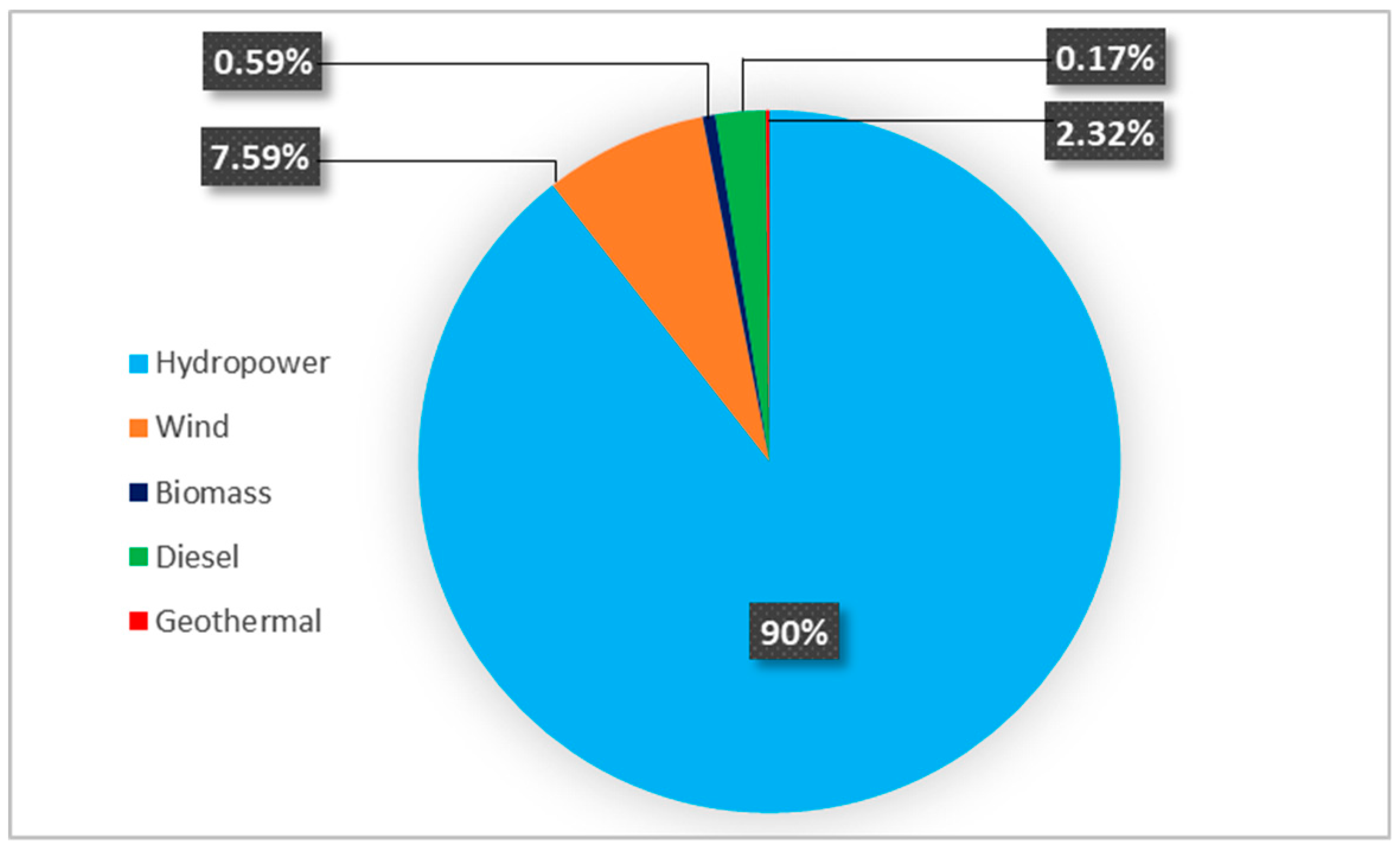
1.1. Overview of Currently Employed Energy Sources and Technologies in Ethiopia

The current access to electricity in Ethiopia is 45%. Access to electricity in an urban area is 92%. However, in rural areas this coverage is reduced to 32.7% [13]. Due to the low development level in the country, the average electricity demand per capita is 52 kWh [14]. Hydropower provides almost 90% of the electricity demand in the country (Figure 1). Solar, wind, geothermal, biomass and other non-renewable energy source contribute to the rest of the renewable energy supply. Diesel power plants contribute small portion (~2%). Energy from biomass, such as wood, crop waste and animal dung has been serving the majority of the population for household purposes [2].
Ethiopia is located in a relatively unique position for the production of renewable energy such as hydropower and wind energy. It has about 45 GW theoretical potential (Table 1) of hydropower capacity, but has only harnessed less than 10% of that potential to date [15]. In 2015, Ethiopia became the second largest power producer in Sub-Sahara Africa when Gilgel Gibe III dam project was inaugurated with a power producing potential of 1870 MW [15]. Currently, the country generates more than 4200 MW of energy mainly from hydropower and could reach up to 10,000 MW when an ongoing projects are finalized [15]. In line with the average increase in the electrical demand of Ethiopia by 30% annually, several cities have been electrified in the last 14–15 years [16]. Table 1 shows the potential of hydropower, solar, geothermal, wind, and biomass in the country.
The current installed electricity-producing capacity consists of eight wind farms, one geothermal power plant, 13 hydropower plants, one biomass power plant and some diesel power plants (Table 2). Additionally, it is evident from this table that Ethiopia is working on more renewable energy resources such as solar and wind which are going to be commissioned in a near future. Because of the emission of greenhouse gases and expensiveness, the use of diesel constitutes an enormous problem in the world [18]. However, the Ethiopian energy policy enhances the use of carbon-neutral technologies, i.e., renewable energy technologies.

1.2. Advances in Renewable Energy Technologies

There are several ongoing projects to increase the Ethiopia’s energy production. The country plans to generate 45,000 MW by the year 2065 from the four renewable energy sources, namely hydropower, geothermal, solar, and wind [15]. One example is the Grand Ethiopian Renaissance Dam (GERD) project. The dam is constructed on the Blue Nile River and will be the largest hydropower dam in Africa and the 10th largest in the world. The project was started in April 2011 with a running cost of 4.7 billion USD. On completion, it is expected to have a reservoir of 74 billion m3 of water and a power capacity of 6000 MW [21]. Therefore, the GERD project will provide cheap and clean electricity to the country and the neighboring countries. Another interesting project used for electricity production is the Reppie waste-to-energy plant. The principle is that rubbish is burned in a combustion reactor and the emitted heat is used to produce steam water that drives a turbine generator to generate electricity. It can generate electricity up to 50 MW [15].
Ethiopia also has high solar power potential, but this is very little exploited to date. The off-grid solar electricity system is mainly dominant in the short term. However, grid-connected photovoltaic (PV) will be dominant in the long term. One instance is, the building of one of the largest African solar power facilities in Ethiopia [20], in a project planned to develop a 100 MW solar PV power plant near the town of Metahara, which is 200 km east of the capital Addis Ababa [20]. The project location covers 250 hectares of unused land next to the main railroad between Addis Ababa and Djibouti. In 2019, the Ethiopian government and Saudi Arabia company Acwa Power signed an agreement to install a 250 MW solar power plant [19]. The power plant is installed in Gad and Dicheto in the Somali and Afar regions respectively. Very recently, Lotus Energy, an Australian company, signed an agreement in Ethiopia with the Tigray Rehabilitation Endowment Fund to install a 500 MW facility power plant in Tigray region [19]. The output of the power from this project will supply energy for 30 years. The cost of the project is estimated to be USD 4.3 billion.
Further to this, the Ethiopia energy sector holds great promise as a source of investment and generates hard currency from neighboring countries. The Ethio-Djibouti transmission line project with 283 km and 230 kV has been exporting 35 MW of electric power to Djibouti on a trial basis and is earning USD 1.3–1.5 million per month [15]. The country has also a transmission line with Sudan which is 230 kV and 296 km long and exporting 100 MW of hydropower. Recently, the Ethiopian and the Tanzanian governments signed an agreement for the selling of 200 MW of power annually [15]. The country was also selling 10 MW electric power to Kenya. Ethiopia could become an energy superpower in East Africa that can generate additional revenues in terms of hard currency. The government of Ethiopia aims to earn up to 600 million USD/yr from power selling to Sudan, Djibouti, Kenya, and Tanzania [21].

1.3. Energy Policy and Strategies in Ethiopia

The aim of the energy policy of Ethiopia is to enhance the reliability and affordability of energy supplies [22]. It also aims to ensure the rational and sustainable use of energy especially from renewable sources. Energy conservation and energy saving measures in all areas is the other energy policy. The policy also deliberates community participation, with an emphasis on women, and encourages legal and institutional frameworks to deal with energy issues [22].
The current Ethiopian electrification system comprises two programs [15]. The Rural Electrification Fund (REF): this is an off-grid program that primarily emphasizes renewable energy technologies through the private sector and electricity service cooperatives. The Universal Electricity Access Program (UEAP): this plan is aimed to deliver electricity for the country-side. The Eastern Africa Power Pool (EAPP) is a regional organization founded in 2005 by its member states including Ethiopia. The aim is to serve the member countries as an interconnector of electricity transmission. The Ministry of Water, Irrigation and Energy (MoWIE) is the federal institute responsible for developing energy policy programs and strategies in Ethiopia. The Ethiopian Electric Utility (EEU), the Ethiopian Electric Power (EEP) and the Ethiopian Energy Authority (EEA) work under the MoWIE, and are responsible for the different energy streams [15].
The national energy policy of Ethiopia aims to generate more power exclusively from renewable energy resources. By 2030, the current 97.6% renewable energy resources will reach 99.3% [22]. By 2025, Ethiopia aims to access universal electricity following the National Electrification Program (NEP) [21]. By that time, the on-grid access and the off-grid access rate would be 65% and 35%, respectively. However, there are limitations in the actual energy supply from these hydropower plants due to uncertainty in seasonal and rainfall patterns and climate change. The policy encourages energy conservation in industry, transport, and major-energy consuming sectors to secure economically and environmentally sustainable power. To provide the ever-increasing demand for electricity, and to deal with the uncertainty in climate change, complementary energy storage and conversion technologies must be established by integrating them with renewable energy resources to alleviate the risk of overreliance on and variability of hydropower. Potential complementary energy conversion and storage technologies include different membrane technologies such as fuel cell, microbial fuel cell (MFC), salinity gradient power (SGP), hydrogen technologies, and batteries.

2. Fuel Cell and Hydrogen Technologies
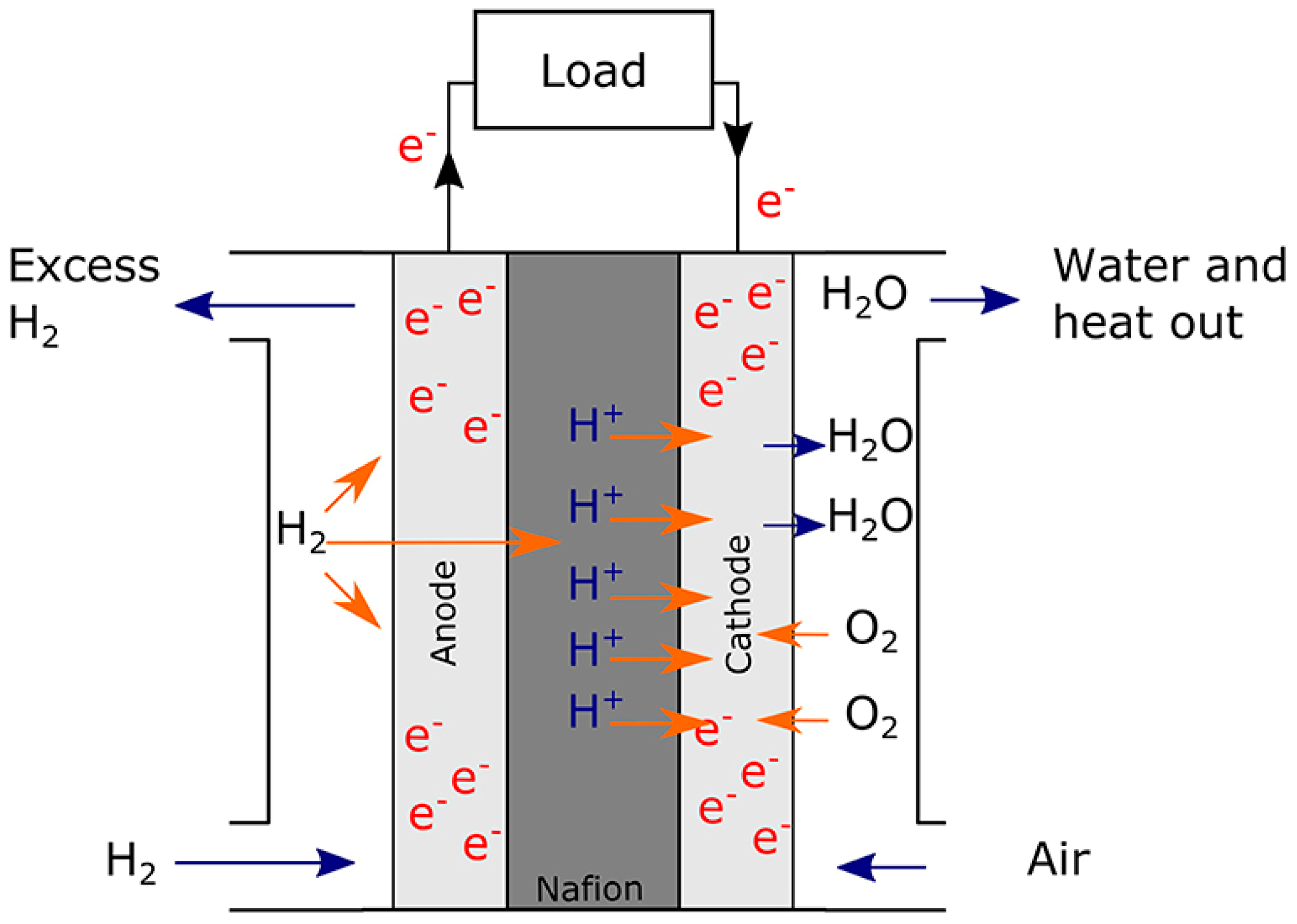
Considering the massive natural resources available for energy production in Ethiopia, for example, natural water bodies, geothermal and natural gas etc., (Table 1) there is a high potential for implementation of various energy conversion and storage technologies. Moreover, the availability of sunlight throughout the year, wind, and other potential energy sources call for suitable membrane technologies to exploit these resources.

2.1. Fuel Cells

A fuel cell allows for the conversion of the chemical energy from a fuel into electricity. Electricity is continuously produced so long as the fuel and oxygen are supplied [23]. The basics of fuel cell technology were first introduced by Swiss scientist Christian Friedrich Schönbein in 1838. The very first fuel cell was practically developed in 1839 by Sir William Robert Grove who accidentally reversed the electrolysis of water. Later on, the first pilot-scale 5 kW fuel cell was demonstrated by Francis Bacon at Cambridge University in 1950 [23]. The first developments were of alkaline type fuel cells which were implemented in NASA as compact power sources for space shuttle applications which later on extended to applications involving stationary powers and transportations.
In a fuel cell, air is fed to the cathodic electrode and hydrogen is fed to the anodic electrode. A general schematic presentation of proton exchange membrane fuel cell is shown in Figure 2. On the anode side, hydrogen diffuses to the anode where it dissociates into positive ions and electrons. Anode and cathode chambers are separated by a cation exchange membrane (CEM) soaked in a liquid electrolyte or separated by solid electrolytes, which permits the flow of positive ions from anode to cathode side while insulating electrons. The electrons are then forced to travel through an external circuit as an electric current. On the cathode side, oxygen molecules react with the electrons and positive ions to form water. The chemical reactions involved in the anode, cathode and overall reactions are:
Anodic side: H2 → 2H+ + 2e
Cathode side: 1/2O2 + 2H+ + 2e → H2O
Overall: H2 + 1/2O2 → H2O
Fuel cells can be of different types and are generally classified based on the electrolyte as this material determines the optimal operating temperature and the fuel used to generate electricity. This also allows for the determination of suitable applications, be it to transport, stationary power, and portable power supply. Table 3 presents a comparison of the different types of fuel cells. For instance, the low operating temperature falls in the range of (50–250 °C) for polymer electrolyte membrane fuel cell (PEMFC), alkaline fuel cell (AFC) and phospheric acid fuel cell (PAFC), and high operating temperature in the range of (650–1000 °C) such as the molten carbonate fuel cell (MCFC) and solid oxide fuel cell (SOFC).
PEMFC is well-commercialized for mobile applications although not efficient as SOFC, which is not yet on the market. However, SOFC is limited by a short life cycle, which makes it unsuitable for a system with long idle periods such as diesel locomotives than railroads. MCFC systems are commercialized in sizes of up to MW power ratings but these systems are limited by lower volumetric power density compared to PEMFC systems. Current versions of MCFC are too large to be packed in the locomotive but well suited for applications that need continuous base-load power such as hospitals and hotels [25]. PAFC is well established commercially with a noted advantage of stable, long term operation reaching up to 40,000 h. However, PAFC exhibits lower power density compared to PEMFC due to the interaction of liquid electrolyte (phosphoric acid) with the Pt catalysts. PAFC is suitable for stationary power generators with up 100–400 kW output capacity and also in large vehicles such as buses and trucks.
Despite the significant research advances in fuel cell technologies, there are still challenges to be addressed for full market penetration. Cost and efficiency are some of the important issues that need to be considered in developing next-generation fuel cells. Availability of Platinum-group metal (PGM)-free electrocatalysts is of high importance for reducing the cost of PEMFC. Currently, established electrocatalysts based on M-N-C (M: Fe, Co, or Mn) exhibit a promising performance but their stability under acidic conditions is an issue for the practical applications. In AFC, although PGM-free electrocatalysts can be used, the activity is not satisfactory which needs to be improved. Moreover, improving the durability of the electrocatalysts in hash alkaline media is of paramount importance. In both PEMFC and AFC, low-cost, and durable membranes with reduced gas cross over are highly important [7,8]

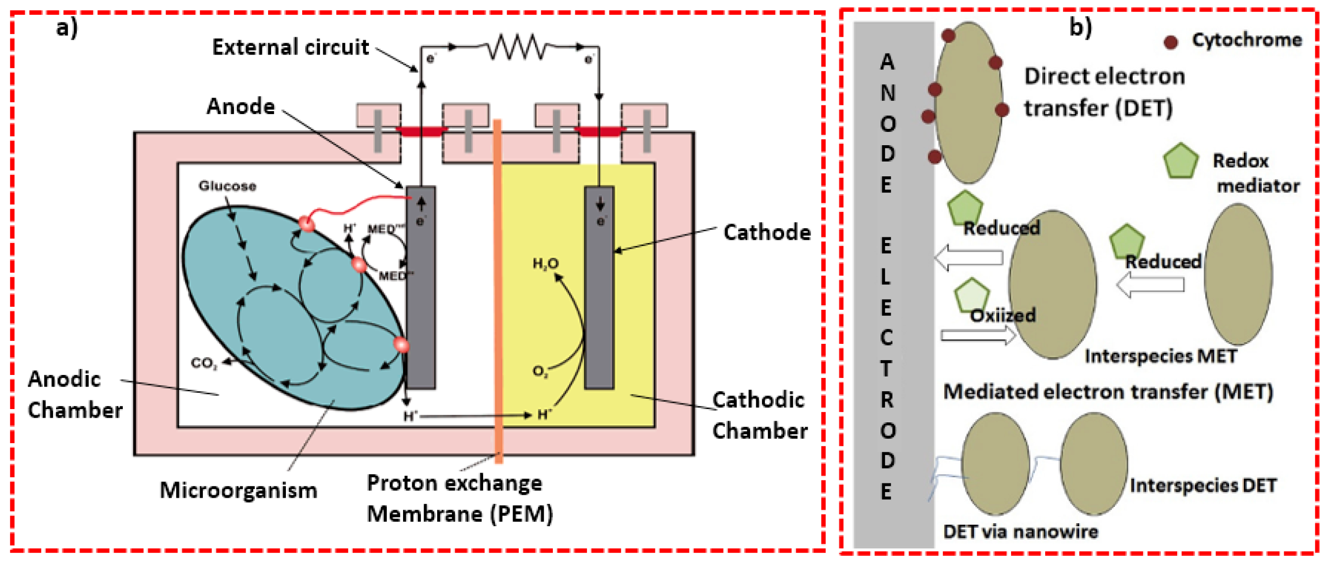
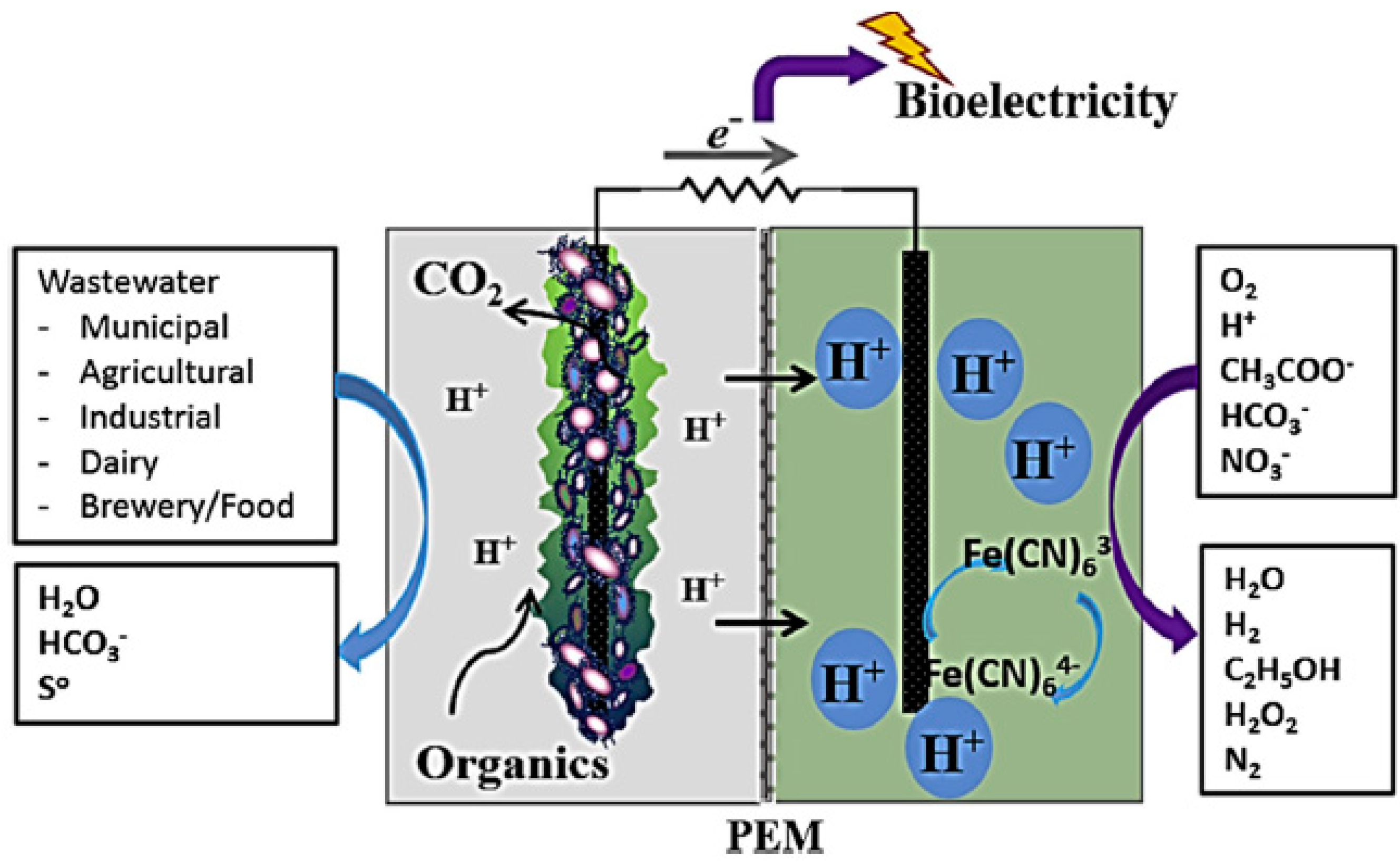
2.2. Microbial Fuel Cell

The microbial fuel cell (MFC) is an emerging bioelectrochemical system (BES) that uses microorganisms (bacteria) as biocatalysts to convert chemical energy in the chemical bond of organic and inorganic substrates directly into bioelectricity [26]. The concept of using MFC for electricity production started at the turn of the 19th century by Potter [27]. However, MFC has gained attention from the scientific community in the last 18 years for the possibility of converting organic resources into electricity. The organic and inorganic substrates used for MFC as the main feed to generate bioelectricity are low-grade biomasses such as lignocellulose, artificial, and real wastewater which is generated every day as a waste [28]. This makes MFC advantageous in terms of environmental sustainability and alternative green electricity generation despite major technical challenges that hinder its practical development [29].
MFC is a bioreactor and mostly comprises anodic and cathodic chambers, which is separated by proton exchange membrane (PEM) (Figure 3). In the anodic chamber, the microorganisms grow and create a biofilm on the solid surface of anode which then degrades (oxidizes) a substrate resulting in the production of protons and electrons. The produced electrons are transferred from the biofilm to the anode electrode (negative terminal) and then flow to cathode (positive terminal) via an external circuit containing a resistor operated under external load. Subsequently, the electrons are used to reduce electron acceptors in the cathodic chamber. The protons also migrate from anodic to cathodic chamber in the electrolyte through PEM and react with the reduced form of electron acceptors [30,31]. In MFC, anode is an electrode that is used for flowing electric current into a polarized electrical device, whereas cathode is an electrode through which electric current flows out of polarized electric device. Figure 3a illustrates the double chamber MFC in which the anodic chamber is inoculated with bacteria and the two electrodes are separated by PEM while connected by an external circuit.
Electron transfer mechanisms in MFC: the main mechanisms of electron transfer in MFC are direct electron transfer (DET) and mediated electron transfer (MET) [33,34]. In DET, electrons are transferred during direct connection of the membrane or membrane organelle of microorganisms with the solid surface of anode electrode without addition of any redox species that assist electron transfer process (Figure 3b). The electron transfer process between the microorganisms and solid electrode surface can be facilitated by c-type cytochromes and conductive wire or pili which links the cell walls of microorganisms to a solid electrode surface [35].
In MET, direct connection between the microorganisms in the biofilm and solid electrode surface is not necessary (Figure 3b). Electrons are transferred indirectly by non-electrogenic microorganisms with the help of redox-active chemical species (electron mediators). Some of the electron mediators excrete by non-electrogenic microorganisms include phenazine, 2–amino–3 carboxy–1, 4–naphthoquinone, 1,2–dihydroxynaphthalene and 2,6–di-tertbutyl-p-benzoquinone [30,36,37,38]
Wastewater treatment and energy generation using MFC: Wastewater is considered to be one of the sources of water, energy and value-added chemicals and nutrients for plant fertilizers. Therefore, direct conversion of wastewater into clean electricity, value-added products and minimize or eliminate the excess sludge by using MFC is of high importance and considered to be a better option compared with conventional wastewater treatment techniques [39,40]. The principles are that during wastewater treatment, electrochemical reactions are taking place inside MFC. These reactions contain Gibbs free energy (negative free reaction energy) and release energy (electric or electron release) spontaneously. The standard cell voltage or electromotive force (emf), ΔE0, can be calculated from the standard free energy as follow (Equation (1)) [39]:
Δ E 0 =   [   v i Δ G i ,   p r o d u c t s 0     v i Δ G i ,   r e a c t a n t s 0 ] / n F =   Δ G n F  
where Δ G 0 is the negative free energies of formation of the respective products and reactants (J/mol), n (moles) of stoichiometry factors of the redox reaction, and F- Faraday’s constant (96,485 C/mol).
The maximum useful work that can be obtained from a reaction of thermodynamic systems can be measured by Gibbs free energy of reaction. If the system of MFC is generating electricity from wastewater, the theoretical cell voltage of MFC (or emf) can be calculated from the difference between anode and cathode potentials as follow (Equation (2)):
Δ E c e l l 0 =   Δ E c a t h o d e 0   Δ E a n o d e 0
The cell voltage of MFC will be positive if the Gibbs free energy is negative, indicating that electrical energy generation from the reaction in MFC is spontaneous. For instance, if the wastewater with a high content of acetate is used as the organic substrate in MFC, and assume that the concentration of acetate ([CH3COO] = [HCO3] = 10 mM, pH = 7 at 298 K. pO2 = 0.2 bar), with oxygen reduction, the combined redox reaction will be as follow [41]:
Anode: CH3COO + 4H2O → 2HCO3 + 9H+ 8e ( E 0 =   0.289 V   vs . SHE )
Cathode: 2O2 + 8H+ + 8e → 4H2O ( E 0 =   0.805 V   v s . S H E )
Overall: CH3COO + 2O2 → 2HCO3 + H+ ( Δ G = 847.6 kJ mol ; emf = 1.094 V )
Different sources of real wastewater such as domestic or municipal wastewater [42,43], agricultural wastewater [44], and industrial wastewater [44,45,46] can be treated and generate electricity using MFC (Figure 4). At the same time, value-added chemicals can be produced in the cathode chamber of MFC or toxic pollutants can be removed from the environment [47].
Therefore, in Ethiopia, the potential sites to implement MFC technology include the municipal wastewater treatment plant, brewery wastewater treatment plant and industrial parks where enormous amounts of sludge and wastewater are generated every day from zero liquid discharge treatment plant and municipality treatment plants [48,49].
The main challenge of MFC technology is that the power output from an individual MFC is insufficient to drive practical applications. Therefore, one of the strategies to boost the power density is to design a series configuration of individual MFC into a stack. For instance, a large-scale MFC with 72 L volume stack made up of 5 membrane-based MFC was designed and 51 W/m3 power density was generated [50]. Another large-scale MFC can also be designed up to 1000 L size, which consists of 50 modules and generated 60 W/m3 while achieving up to 90% COD removal when operated with real municipal wastewater for a year [6].

3. Advantages of MFC

MFC has several advantages over other available technologies (Figure 5). MFC is a versatile technology and can be used for electric generation, wastewater treatment, recovery of pure materials, removal of organic matters, water softening, bioremediations, dye decolorization and biosensor applications [39,47,51,52].
It generates clean electricity direct from organic matter in wastewater without any pre-treatment of the wastewater such as separation, and purification. It can generate about 1.43 kWh/m3 from a primary sludge or 1.8 kWh/m3 from treated effluent wastewater [53]. MFC also saves energy by treating wastewater anaerobically and avoid the energy used for aeration in conventional wastewater treatment techniques. It consumes only 0.024 kW or 0.07 kWh/kg-COD for feeding and mixing in the reactor compared with the energy consumed by the activated sludge-based aerobic treatment method which consumes about 0.3 kW or 0.6 kWh/kg-COD [54,55]. However, for the production of methane and hydrogen using MFC in an anaerobic digestion process, the wastewater needs to be separated and purified before use. MFC is environmentally friendly as it can be operated under mild conditions at room temperature.
Moreover, MFC produces much less sludge during wastewater treatment (0.06–0.16 gVSS/gCOD) compared to the sludge produced by active aeration (0.35–0.45 gVSS/gCOD) [47]. This indicates that unlike other conventional wastewater treatment technologies, sludge management during wastewater treatment using MFC is not a major concern.

3.1. Hydrogen Production Technologies

Steam reforming of methane (hydrocarbons) has been commonly employed for the production of H2 gas. However, the CO2 emission is substantial. Hydrogen can be produced by electrolyzing water at low temperature (LT) and high temperatures (HT). The LT electrolyzer works at a temperature (<100 °C) and the HT electrolyzer works between (700–1000 °C) [56,57]. Alkaline electrolysis (AE) and PEM electrolysis used LT electrolysis system. LT electrolyzer has several advantages over natural gas reforming/coal gasification such as on-site, on-demand generation, high-quality hydrogen, and unit modularity. The HT electrolyzer is known by the name solid oxide electrolysis cell (SOEC).

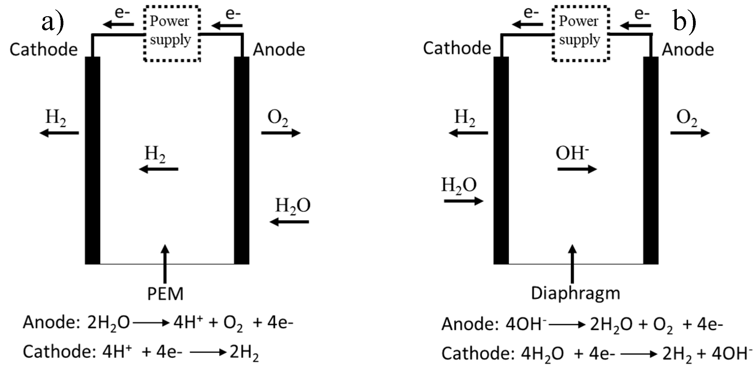
3.1.1. PEM Electrolyzers

The PEM, is a young technology and was developed by General Electric [58]. In certain areas of application, this technology already penetrated the market [56]. PEM has used an acidic solid polymer as an electrolyte instead of a liquid electrolyte and acquired its name as polymer electrolyte membrane PEM. The membrane is used both as an electrolyte (conducts H+ from anode to cathode) and to prevent mixing of the O2 and H2 gases. The half-cell reaction and the schematic of PEM are explained in Figure 6. The PEM has several advantages over the AE. These are: faster reaction kinetic for hydrogen production, safety related to the non-appearance of KOH as an electrolyte, high purity of H2 gas, little cross over, lower energy consumption, easy handling and maintenance, high-pressure operation in the cathode side and whereas anode can be operated at ambient temperature [56].
Perfluorosulfonic acid polymers (PFSA) membranes such as Nafion®, Flemion®, and Fumapem® have been used in PEM. The PFSA membranes have high oxidative stability, good strength, good proton conductivity. The lifetime of the membrane is about 10,000 h and proton conductivity as high as 0.1 S/cm [58]. The membrane thickness is about 100 µm to 200 µm. The typical electrode material for the cathode and the anode are Pt and IrO2 respectively. However, other materials such as Pt-Pd alloys at the cathode and RuO2 in the anode can also be used [56]. The use of these scarce metals especially Ir will significantly limit the production of hydrogen with PEM electrolyzer. To get higher current densities by PEM, easily available catalyst, and corrosion-resistant materials such as bi-polar plates containing high-quality titanium is needed. With regard to these advantages, an anion exchange membrane (AEM) that combines the advantages of both PEM and AE has been devised [56].

3.1.2. Alkaline Electrolyzers

Alkaline electrolysis (AE) is the most widely used electrolytic technology for H2 production. This is the oldest technology; on the other hand, it is one of the suitable technologies for hydrogen production from water. AE uses 20–30 % KOH by mass as an electrolyte in two electrodes (cathode and anode) system. The cathode and the anode are mostly Ni and Ni alloys [56]. The gaseous products (O2 and H2) are separated by as thin diaphragm. Water and the hydroxide ions (OH) are passed through the diaphragm. The schematic of the alkaline electrolysis is given in Figure 6b. One of the main limitations of AE is, the KOH is corrosive and it should be handled with care. Additionally, the mobilities of the OH is moderate and this results in limited current densities. Problems related to the incapability of the diaphragm to prevent the crossover of the hydrogen and the oxygen gases raises safety issue and reduces the efficiency of the process. Moreover, the relatively high energy consumption, installation and maintenance costs, safety and durability are the other limitations [56,58].

3.1.3. High-Temperature Water Electrolyzers

The high-temperature water electrolyzer is principally the solid oxide fuel cell (SOFC) run in ‘reverse’ mode. Surplus electricity generated by e.g., wind, geothermal and solar can be used for the production of hydrogen. The SOEC can also electrolyze CO2 to CO. When the CO2 and H2O are electrolyzed, a mixture of hydrogen and CO are produced. This mixture is known as syngas. It is the starting material to synthesize several hydrocarbons in the chemical industry. The thermodynamics of the process makes the high-temperature water electrolyzers favorable. Compared to the rise in the thermal demand, the electricity demand of the high-temperature water electrolyzer decreases considerably [58,59].

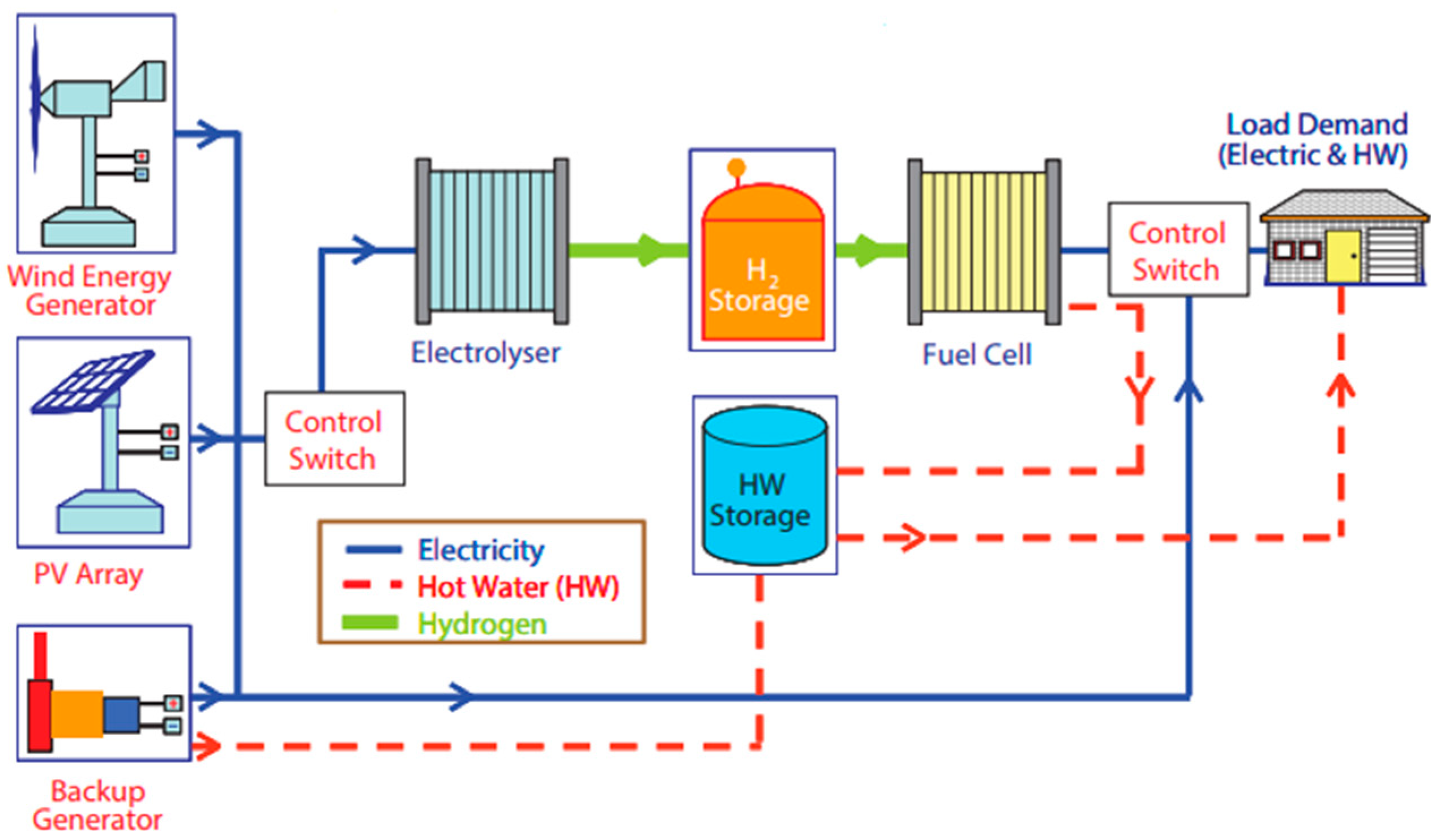
3.1.4. Hydrogen Production from Renewable Power Sources

Hydrogen is a prominent and important energy carrier and storage for the future. When hydrogen is produced from water and combined with renewable energy sources (solar, wind and ocean), it has a near-zero greenhouse gas emission. Hydrogen could be used for load leveling and peak load shaving for other renewable energy sources [9,57,60]. Based on the end user applications, hydrogen can be stored and converted to power and heat in a fuel cell and combustion engine as per the load demand.
The LT electrolyzer can be integrated with intermittent renewable energy sources such as solar PV, wind turbine, and non-intermittent ones such as reverse electro dialysis (RED) and PRO, as well as other renewable energy sources [9,10,57]. This renewable energy input for LT electrolyzer can increase the efficiency of the system by up to 75–80% [9,10,57]. Figure 7 shows renewable hydrogen production pathways and applications. In this system, hydrogen can be stored and operate PEMFC to provide energy during high load demand. The system can have a diesel generator and hot water storage tank. The thermal energy in HT can reduce the high electricity input required in the case of the LT electrolyzer.
In addition to photovoltaic array and wind turbine, it is also possible to use other renewable energy power sources for the electrolyzer. The concept of integrating reverse electro dialysis (RED) driven water electrolysis for hydrogen production was demonstrated recently by Tufa et al. [9,10]. Provided that the potential of wind and geothermal energy in Ethiopia, hydrogen can be produced from water by integrating it with these renewable power sources.

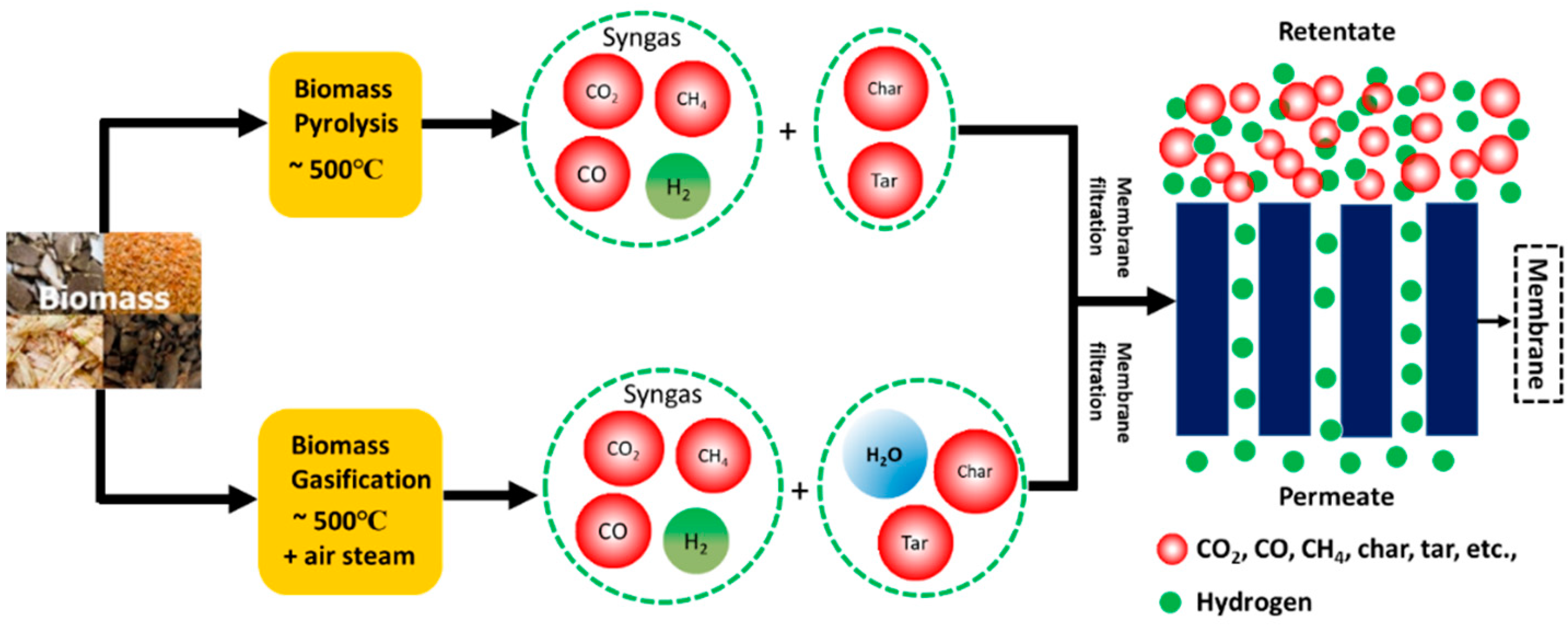
3.1.5. Hydrogen from Biomass

In addition to water electrolyzer, hydrogen can be produced from biomass. Biomass is one of the most important energy sources and estimating to contribute in the range of 9–15% on a global scale [11,61]. This biomass energy is the pillar for the total energy consumption especially in sub-Saharan African countries including Ethiopia [62]. In 2010, biomass energy has accounted for 91% of the total energy consumption in Ethiopia [17]. However, the biomass is used in direct burning of open fire and leading to indoor air pollution that pays for the suffering of millions of people [61].
The four biomass energy resources are woody biomass (logging residuals, sawmill wastes), agricultural waste (crop straw, animal wastes, etc.), energy crops (commercial crops, grass, etc.) and municipal and industrial waste (waste paper, sewage sludge, etc.) [11,63]. The rural community of Ethiopia is highly dependent on woody biomass and agricultural residues for its energy consumption [61]. Biomass is tipped as one of the potential raw materials for hydrogen production as clean and environmentally friendly energy carrier. Currently, most of the hydrogen produced industrially is prepared from fossil fuels (i.e., methane) via steam reforming and water gas shift reaction as shown below [64].
CH4 + H2O CO + 3H2 → (steam reforming)
CO + H2O CO2 + H2 → (water gas shift reaction)
Thermochemical and biological routes are the two processes used to produce hydrogen from biomass. Gasification, pyrolysis, combustion and liquefaction processes are included under the thermochemical route and dark fermentation, photo-fermentation, biogas (methane) production, bio-photolysis and biological water gas shift reactions are under biological route [11,60].
Biological hydrogen production has a stringent requirement in terms of feedstocks and reaction conditions and it is also time-consuming. On the other hand, the two thermochemical routes, namely pyrolysis and gasification (Figure 8) are practical for hydrogen production since they are less selective in the feedstock, have faster reaction kinetics, fairly lower cost and efficiency (>50%) [11].
Following the reaction explained in Figure 8, the hydrogen gas needs to be separated from the rest of the gases to ensure high-quality hydrogen product, recycle the unreacted gases and to capture the greenhouse gases to avoid their emission into the atmosphere [11,65]. Membrane separation and purification for hydrogen are one of the most important applications. The advantage of membrane filtration technologies overpressure swing adsorption (PSA) is the simplicity of operation, small footprint, reduced power consumption and continuous operation. The mechanism of the separation lies in hydrogen selectively passing through the membrane driven by the partial pressure of the hydrogen in the feed side. The selectivity of hydrogen also depends on the membrane type/material. Polymeric membranes, dense metal membranes and microporous (nano-porous) membranes have been employed for hydrogen production [11,65]. Each of the above membranes have their own distinctive features (Table 4). Extensive information on membranes for hydrogen serration is found in [11].
Ethiopia has a considerable amount of biomass residues and its potential to renewable energy [61,63]. These biomass residues are not being used and collected properly but can be used to produce renewable energy such as hydrogen gas without affecting the socio-economic aspect and compromising food security. The share of the various biomass resources as a fuel covers 69% wood, 13% residue (vegetable, cereals, coffee, grass and forest), 14% cattle dung and 4% charcoal in 2013 [61]. Agricultural residues are vital sources of biomass for fuel; however, its use rates account for only 30% [66]. Therefore, hydrogen gas production can increase the use rate of agricultural residue in the country. Up to 92% of Ethiopian households use biomass as energy sources for cooking and heating [66]. For instance, according to a report in 2018, wood for charcoal production and charcoal production in Ethiopia reached 109,389,000 m3 and 4,317,000 Mt respectively. For this reason, the dependence of biomass for cooking in the country leads to an increase in the emission of 1.4 million tons of CO2 between 2005 to 2010 [17]. In terms of per capita, this resulted in 0.06 tons of CO2 in 2005, 0.075 tons in 2010, and 0.19 tons in 2014.
Considering the increase in demand for fuel in the future and the potential of biomass for renewable energy production, hydrogen can be a useful and fine energy source in the country. The energy policy is mainly centralized in increasing the renewable energy program exclusively from hydropower. However, hydrogen is already proposed to substitute petroleum-based fuel and countries are backing hydrogen-powered vehicles and funding for its smooth production from biomass [11]. Therefore, we recommend that the Ethiopian government also follows a similar suite to increase the renewable energy reserve from biomass via hydrogen gas production.

4. Salinity Gradient Energy Technologies

Salinity gradient energy, also called “blue energy”, is a clean, renewable energy generated by mixing two salt solutions of different concentrations, for instance, seawater and river water. Reverse Electrodialysis (RED) and Pressure Retarded Osmosis (PRO) are the two most advanced technologies for salinity gradient power (SGP) generations.

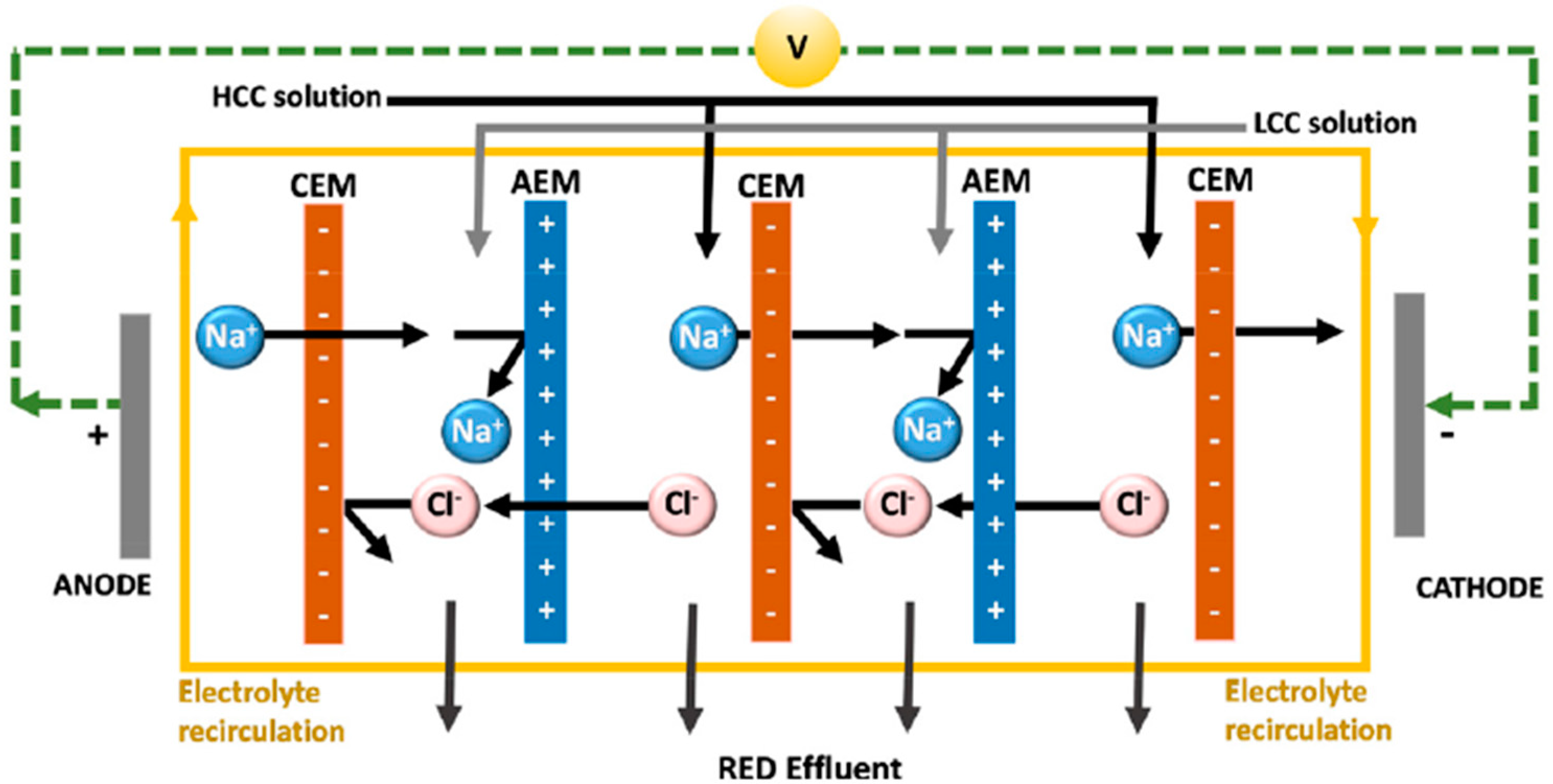
4.1. Reverse Electrodialysis (RED)

RED is one of the most promising membrane-based technologies for generation of electricity by mixing solutions of different salinity. The historical development of electrodialysis (ED) returns to the early days of 1954 when Pattle performed the first experiments on small-scale RED [67]. However, the topic was not given much attention at the time mainly due to the limited membrane availability. However, with the rise in global climate change issues as well as the expansion of membrane markets, research on RED started gaining much more attention with time. Despite several studies on RED so far, significant research findings were reported from the early periods of the 2000s. For instance, in 2011, Vermass et al. reported a maximum power density of 2.2 W/m2 (the maximum so far at ambient temperature) for RED equipped with a special ion-exchange membranes (Fumatech, Germany) prepared on demand, and operated with seawater (0.5 M NaCl) and river water (0.017 M NaCl) solutions [68].
Figure 9 illustrates the scheme of a RED system for salinity gradient power (SGP) generation. In RED, cation exchange membranes (CEMs) and anion exchange membranes (AEMs) are alternately aligned in a way to create two compartments: a high concentration compartment (HCC) and low concentration compartment (LCC). When the compartments are filled with the respective salt solutions of high concentration and low concentration, a salinity gradient is created that initiates the selective transport of ions through the ion-exchange membranes. Electrical energy is generated by redox reactions occurring over the electrodes [3,67]. Theoretically, the total electromotive force, or the open-circuit voltage (OCV), generated in RED is expressed by the Nernst equation:
OCV NRT F [ α CEM z cn ln γ c c c γ d c d + α AEM z an ln γ c c c γ d c d ]
where N is the number of membranes (cell) pairs, α is the permselectivity of the ion-exchange membrane, z is the valence of ions, γ is the activity coefficient of ions, c is the activity of ions in solutions, subscripts ‘cn’ and ‘an’ stand for ‘anion’ and ‘cation’, respectively. OCV is mainly dependent on the valence of the transported ions, the permselectivity membranes and the concentration gradient. By considering 100% permselectivity of the membrane, the theoretical OCV obtained by mixing seawater (0.5 M NaCl)/river water (0.017 M NaCl) is about 0.16 V whereas the theoretical OCV for brine (5 M NaCl)/seawater (0.5 M NaCl) is about 0.12 V [4].
The overall process performance and efficiency in RED are determined by IEMs. The key membrane requirements for RED are low resistance (< 1 Ω cm2) membrane with high permselectivity (>95%) [3,69]. Unlike fuel cell and electrolyzers, the membrane in RED is in contact with neutral pH so the stability or mechanical properties of membranes are not a big issue. The global RED system is supposed to be operated by NaCl salt solutions, with the majority of the ions transported across the membranes being Na+ and Cl. However, under natural conditions, other ions such as Mg2+ and SO42− could be present and proved to have a negative impact on the performance of RED requiring special membranes [69]. The presence of divalent ions in the feed solutions have been challenging to optimize the performance of RED, in particular, the presence of Mg2+, which was observed to reduce the power density of by more than 50% with respect to RED operations using divalent ion-free solutions [69,70]. The efficiency of RED under realistic natural conditions is enhanced by using monovalent selective membranes that are able to reduce the transport of divalent ions. In addition to natural (NaCl-based) SGP sources, other types of SGP sources can also be harnessed. For example, artificial salinity gradient power sources created by using thermolytic salt solutions such as NH4HCO3 allows for clean energy generation in RED with a special advantage being that the solutions at the outlet can be regenerated by using low-grade waste heat sources available from industries for free [71,72]. Thus, such design allows for the conversion of low-grade waste heat into electricity.
In stand-alone applications, RED can generate electricity as long as salt and freshwater are present irrespective of the weather conditions unlike wind and solar energies. The generated electricity can be directly connected to the grid or stored by other technologies. However, mass production of clean energy by RED requires an industrial scale-up which has still not yet been achieved. Nevertheless, several efforts have been made to advance RED toward large-scale implementation. The most notable one was a pilot-scale RED system demonstrated under the scheme of an EU-FP7 REAPower project [73]. The stack equipped with 125 cell pairs and IEM with an active area of 50 m2 was installed in the south of Italy (Sicily), was the first of its kind to operate with artificial brackish water (0.03 M NaCl) and saturated brine (4–5 M NaCl) reaching a maximum output power of 60 W.
Innovative applications of RED can also be implemented in hybrid systems. For instance, a RED coupled with desalination technologies such as reverse osmosis (RO) or membrane distillation (MD) allows for simultaneous potable water and electricity generation. Tufa et al. [74] demonstrated practically the application of RED for power generations using hyper-saline MD brine which allows for the implementation of a low-energy desalination system with near-zero liquid discharge [74]. Such an approach has an enormous advantage from energy and environmental point of view. When coupled with microbial fuel cells (MFCs), i.e., creating a system termed as Microbial RED Cell (MRCs), RED reduces the typical voltage reversal problems in MFCs. RED can also be coupled with microbial electrolysis cells or alkaline electrolysis cells for renewable hydrogen production [75,76]. RED can also function as a flow battery for large-scale energy storage. The approach follows the use of especially designed cells termed as ‘concentration gradient flow battery’ which are able to store energy in the form of the concentration difference between the two electrolyte solutions [77].
Potential of an advanced integrated system for the generation of clean water (e.g., by RO) and energy (e.g., by RED) in Ethiopia is clearly possible in some areas. The Afar depression is a vast desert expanse between Ethiopia, Eritrea, and Djibouti. This area is a source of large deposits of salts and brackish water as well as ground water which are used, among others, in some RO desalination plants in the area [19,73]. The power consumption for the such RO desalination plants and the intake pumps is mainly provided by a rechargeable battery and wind turbine. Moreover, its well known that RO rejects or RO brine produced after desalination have a major environmental issue. For instance, the discharge of RO brine into water bodies is associated with an adverse impact on aquatic organisms. Brine treatment and disposal itself is even an extra cost that otherwise can be exploited differently for other beneficial purposes. For instance, RO brine can be used as a feed to RED for electricity generation. Thus, the extra power supplied by RED presents a huge potential to compensate for the energy consumption by the RO unit through the implementation of an integrated RO-RED system. Such an approach has been recently investigated with the advantages demonstrated in terms of both energy and environment for different configurations [69,74,75,76]. In fact, the groundwater used as an RO feed is hot, as the region itself is known to have the daytime temperatures of more than 40 °C in the long hot season. Eventually, the use of such hot, saline groundwater directly in RED is another strategic approach for enhanced power generation at high operating temperatures maintained with no added cost.
A significant research effort is still required to realize reverse electrodialysis commercially. The availability of low resistance and highly permselective IEM is the key challenge. The current membrane price for low resistance commercial membranes is very high (˃50 €/m2). To meet the commercial threshold in power density (~5 W/m2) and membrane price (<2 €/m2), new aspects in the design of very thin ion-exchange membranes based on low-cost raw materials is very crucial. Moreover, when it comes to practical implementation RED under realistic natural conditions, design of special membranes able to selectively pass only monovalent while retaining multivalent ions or identification of suitable feed pre-treatment technologies is crucial.

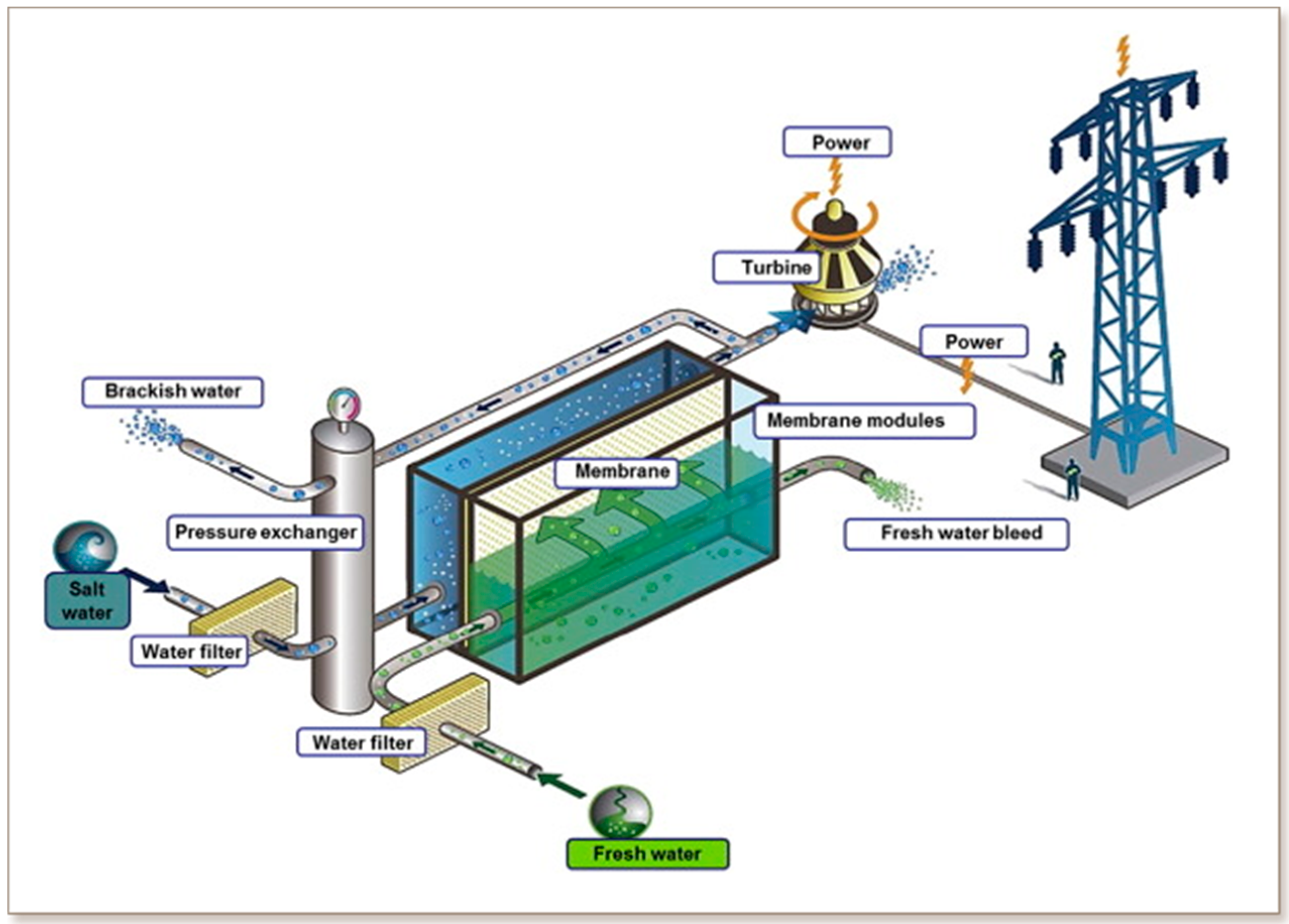
4.2. Pressure Retarded Osmosis (PRO)

PRO is one of the membrane-based technologies for SGP production. It uses a semipermeable membrane through which a low concentration solution (LCS) permeates into high concentration solution (HCS) (Figure 10). The PRO method was invented by Prof. Sidney Loeb in 1973 at the Ben-Gurion University of the Negev (Israel) who reported the first PRO results using a hollow-fiber seawater RO membranes [78]. Later on, Loeb himself patented another approach to PRO functioning in as a closed-loop osmotic heat engine able to convert the heat energy into mechanical work by engineered osmosis [79]. In the 1980s, up to 1.6 W/m2 power density was achieved from experimental studies on PRO [80]. Later, other researchers further developed the technology through model development to depict the performance of PRO [81], studies on the effect of concentration polarization [81], membrane development and testing [80]. From the 2000s onwards, several studies were conducted on the development of PRO. Statkraft and the Foundation for Scientific and Industrial Research at the Norwegian Institute of Technology (SINTEF) reported a study on the regional and global potential of PRO [82,83]. In 2009, the world’s first osmotic power plant based on PRO was demonstrated by Statkraft in Norway [84]. The other prototype is hybrid RO-PRO prototype which was built in 2010 by the ‘Mega-ton water system’ project in Fukuoka, Japan. It was designed to operate with seawater reverse osmosis (SWRO) and wastewater reclamation systems for power generation [84].
The resultant brackish water is obtained when the LCS is diluted by the water flowing through the semipermeable membrane, and the freshwater at the outlet are both returned to its source [86]. River, brackish and wastewater can be used as LCS and seawater and brine can be employed as an HCS (draw solution). Before feeding to the PRO, any contaminants and impurities can be removed by pretreatment to reduce membranes fouling. When water permeates into HCS, the solution is pressurized and the stretched volume drives the external turbine to produce electricity [3]. A pressure exchanger is used to recover part of the pressurized HCS thereby reducing the cost of the technology. Osmotic water flux Jw in PRO can be obtained from the membrane water permeability A and the driving force which is related to the osmotic pressure difference (Δπ) and the hydrostatic pressure difference (ΔP) as [87]:
J w = A ( Δ π Δ P )
Thus, the power density Pd produced in a PRO process is the product of the augmented flow rate and pressure drop through a hydro-turbine:
P d = J w Δ P = A ( Δ π Δ P ) Δ P
The main research on PRO in recent years is mainly focused on the improvement of power density by optimizing the various parameters in the system including optimization of the feed type and concentration of the draw solution, membrane development and fouling reduction, hybrid applications (e.g., integration of PRO with another system such as RO). Similar to RED, membranes are the key component in PRO system. To achieve acceptable power density, a PRO membrane should possess high water flux, high rejections of salts and low reverse flux and minimized internal concentration polarization. Flat sheet and hollow fiber membrane are the most common ones used in PRO experiments. For instance, cellulose triacetate (CTA) membrane, is one of the most widely used flat sheet membranes. Flat sheet thin film composite (TFC) membranes also have a huge potential in PRO applications. The hollow fiber membrane is attractive option in PRO application because of its self-mechanical support, spacer free module, high packing density, flow dynamics, small footprint and easy in scale-up [88]. However, an improvement in water permeability and mechanical robustness are still the challenges in the development of PRO membrane. Table 5 shows the power density obtained from PRO system for different membranes at varying salt concentration. Generally, the TFC membrane provides higher power density than TCA membranes mainly due to higher water flux and lower concentration polarization effects.
Most laboratory-scale PRO tests employ seawater (~0.5 M NaCl) and SWRO brine (~1.0 M NaCl) as a draw solution [88]. The most common feed solutions used in PRO is river and wastewater or a mixture of the two [3]. River water/seawater was already tested in PRO but such scenarios result in low energy density. The use of brine from MD or RO allows for the development of a hybrid process such as PRO-MD and PRO-RO. Such designs have a huge advantage in terms of high output power and environmental protection. To boost the PRO process for commercialization, further research is expected focusing on the design and development of optimal membranes and the development of pressure exchanger devices to reduce energy consumption. A membrane with high anti-fouling characteristics and a long lifetime could reduce the operational and capital costs of PRO. For instance, new inorganic and polymeric membrane materials for higher power density has been proposed recently [88].
Ethiopia is a landlocked country with no access to the sea; however, with about 7000 km2 of inland water bodies with high potential of serving as LCS, Ethiopia is called the waterfall of Africa. It has 11 freshwater lakes such as Lake Zeway, Lake Tana, Lake Abaya, Lake Chamo, Lake Abbe, Lake Langano, Lake Zengena, Koka reservoir, Lake Hyqe, Lake Gummare, Lake Hwassa and 9 saline lakes such as Lake Afrera, Lake Karum, Lake Abbe, Lake Abijatta, Lake Ashenge, Lake Basaka, Lake Chew Bahir, Lake Shala and Lake Turkana.
The presence of such freshwater and saline water resources implies the existing potential of SGP in Ethiopia. For instance, the hypersaline Lake Afrera and Karum, which are located in the northern part of the country (Afar region) in the geological depression termed “Denakil Depression” (Figure 11), can be considered to be a promising source of salty water. Lake Afrera exhibits huge mounds of salt built on the lake shores due to extreme salt concentrations, and this area is also used for salt extraction by the Afar people. There are also local companies producing salt from the lake by pumping the brine into artificial ponds for evaporation and subsequent precipitation [89,90]. Lake Karum (also called Lake Asale) is also another hypersaline lake exhibiting a lake-bed forming a jet white salt crust arranged in irregular contours that smoothly submerges in the clear water lake. At the north of this lake is also a mining settlement called “Dallol”. The brackish water or brine existing around such salty lakes and mining sites can be a promising potential location where SGP can be implemented. In principle, the availability of fresh water is crucial to harness the SGP by mixing with the salty water. One potential source can be Awash river with the largest part of its Basin located in the arid lowlands of the Afar Region. There are also other saline lakes in different regions such as Lake Shala, Lake Ashenge, Lake Turkana, which can be potentially harnessed for SGP. Other potential sources of SGP include brine contained in the waste stream of geothermal power production sites, for example, at the Aluto-Langano geothermal power station with a net power generation capacity of 7.3 MW. Groundwater, providing more than 90% of the water used for domestic and industrial supply in Ethiopia, can also be used as a potential source of SGP. In addition to these, municipal and hospital effluents can serve as the HCS in PRO leaving PRO in the heart of energy-producing technologies at a small scale. Nevertheless, all these potential SGP sources require the accurate study of the salinity levels in the various parts of the country. Studies are also required to evaluate the existence of saline wastewater from industrial or domestic sources.
Cross-border developments in cooperation with neighboring countries such as Eritrea and Djibouti is also another aspect that can be considered when it comes to the exploitation of SGP. The SGP technologies can be implemented in different designs: (i) as standalone systems using the Red Sea as saline water sources or (ii) in hybrid applications with modern, largescale desalination facilities such as RO, which is still required to boost the clean water supply of these countries. This is one way to enhance the strategic relationships of such countries in exploiting the electrochemical potential of their freshwater and salt resources.

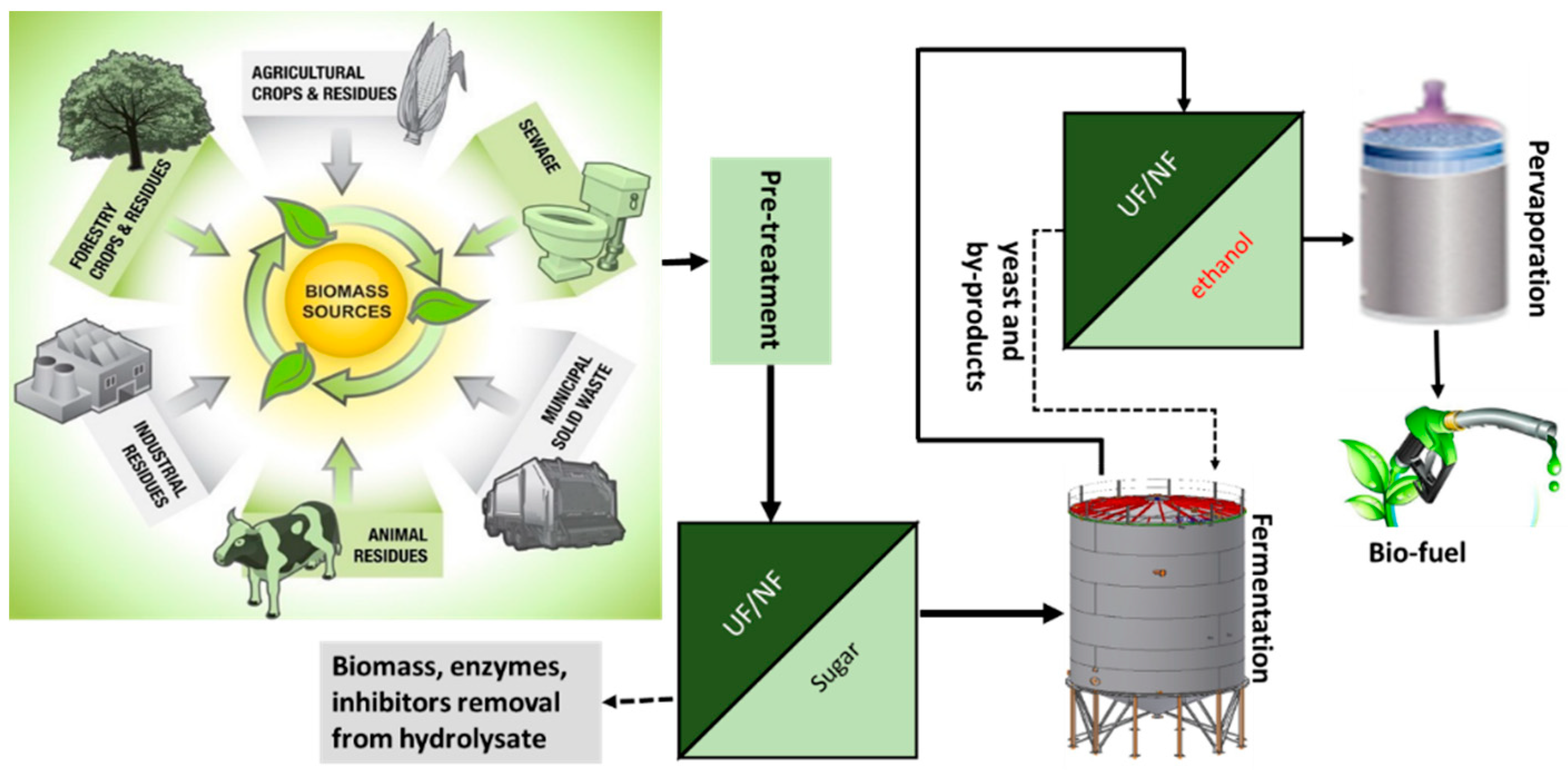
5. Membrane Technology for Advanced Biofuels Production (Bioethanol and Biodiesel)

Biofuels are among the alternatives to tackle the challenge of fossil fuels [92]. As shown in Figure 12, the production of biofuels follows three fundamental steps: Pretreatment and milling/grinding, enzymatic hydrolysis, and fermentation. Membrane separation technologies in biofuel production generally play a great role, particularly in fermentation feed separation and enzyme recirculation. This has a huge benefit in terms of reducing production costs, removing fermentation inhibitors and balance hydrolysis with fermentation [93].
Food crops and oils seeds are known to be the primary sources for first-generation biofuels production. However, the desired targets in achieving biofuel production are limited by some factors such as cost and limited greenhouse gas (GHG) reduction or environmental benefits. Therefore, the development of second-generation biofuels production based on non-food crop feedstocks is envisaged to overcome some of the drawbacks of first-generation biofuel production.
The two most common liquid biofuels produced from biomass are bioethanol and biodiesel [66]. Ethiopia has a high potential for biofuel production. The availability of biomass for bioenergy production was estimated to be 750 PJ/year [61]. Of which forest residue contributes the highest (i.e., 47%). The share of the other biomass is; 34% crop residue, 19% livestock waste and 0.05% municipal solid waste. Currently, the countries’ strategic plan is to produce bioethanol from sugar beet, sugar cane, sweet sorghum and others and biodiesel from jatropha and castor [66]. Additionally, the country’s potential of producing bioethanol from other raw materials such as molasses and eucalyptus trees remains high. Ethiopia currently produces 28 million liters/yr ethanol from two plants using molasses in the sugar factory [66]. There are 13 sugar factories, of which eight are completed and five are under construction. When the new factories start production and the expansion to the other factories is complete, the ethanol production from molasses will be significantly increased.
Biodiesel is among the biofuels which are gaining greater attention pertaining to its ability to substitute fossil fuels. Owing to the disadvantages in the enzymatic transesterification process for the production of biodiesel, research in modeling, designing and controlling efficient bioreactors with immobilized enzymatic transesterification are underway for industrial-scale production [94].
Hydrogen gas can be produced from bio-oil by catalytic membrane reactors through auto-thermal reforming with high conversion efficiency. A study in the immobilization of biological catalysts such as enzymes or whole cells on synthetic membranes under mild conditions has been well-assessed. The synthetic membrane can replicate the cell membrane function of protecting the enzymes from contaminants and inhibitors [95].
In a membrane bioreactor (MBR), the selective membrane is used to confine the biocatalyst in a well-defined space. In a biocatalytic membrane reactor (BMR), the enzyme is immobilized on the membrane, by absorption or entrapment within the polymeric structure of the membrane, in which only the product is allowed to pass through the membrane [96]. The different types of MBR for the production of biofuels include enzyme membrane reactors (EMR), enzyme gel-layer membrane reactors, membrane segregated enzyme reactors, membrane-bound enzymes in continuous flow reactors, and whole cells or enzymes immobilized in capillary membranes reactors [97]. For possible use of MBR in second-generation biofuel production at pilot-scale and industrial-scale, certain aspect of the system such as separation and recycling of the biocatalyst, immobilization of the biocatalyst on the surface of the membrane by covalent bond and entrapment of the biocatalyst has to be clearly defined [98]. Although direct immobilization of enzymes on the membrane has several advantages, it does not allow for the regeneration of neither the membrane nor the enzyme when the BMR is either over fouled or the enzyme is denaturated. Gebreyohannes et al. showed a new and innovative strategy to reverse immobilize enzyme over the surface of the membrane [99]. This new class of stimuli-responsive BMR was able to reduce the major issues faced when using BMRs for large scaler production of bioethanol from biomass including easy enzyme recyclability, prevent enzyme-product inhibition, in situ membrane foulant degradation, continuous operation at high solid loading and solid loading rate and high bioethanol productivity per mg of enzyme. It also allowed process intensification through the possibility of co-immobilizing various types of synergistically performing enzymes in a single stage reactor [100].
Currently, Ethiopia blends bioethanol in vehicle fuel to save hard currency. By 2030, the Ethiopian government envisages blending further 5% in transport fuel. Since 2008, the country has saved USD 30.9 million on oil imports by mixing 38 million liters of bioethanol with fuel [66]. Considering, the high potential of biofuel production and the country’s policy to blend more biofuel to transport fuel, high-quality biofuel is needed. To achieve these, we recommend using membrane technologies such as MBR for biofuel production. The main advantages of using MBR for biofuel production are, simplicity in product recovery, excellent separation efficiency, reduced energy demand, operation in continuous mode, excellent product and biological conversion rate, and others [101,102]. The conventional techniques to remove concentrated ethanol is through distillation and has several disadvantages [92,102]. High energy consumption at low alcohol feed concentration (< 5 wt/%.), not appropriate to obtain high concentration of ethanol and the distillation temperature can deactivate the proteins and enzymes and blocks the use of microorganisms. These limitations can be compensated by membrane technologies such as RO, ultrafiltration and nanofiltration, pervaporation, hybrid technologies including pervaporation-distillation techniques. Therefore, clean biofuel can help to increase the octane number, thereby increasing the anti-knocking properties of the engine to keep healthy vehicles, decreases GHG emission and promoting renewable energy technologies.

6. Membranes for Energy Storage Electrochemical Devices

Energy storage is the key to efficient use and clean generation of energy. Thus, low-cost, energy-efficient, safe and large-scale energy storage systems are essential to match the energy supply and demand [103,104]. This avoids energy wastage, thus enhancing the system flexibility, and improving energy management efficiency. Overall, it plays a positive role in creating a low-carbon world economy. There are several criteria used in selecting a specific energy storage technique. The main factors considered are (i) availability of energy resource, (ii) energy requirement and application, (iii) storage efficiency, (iv) cost and (v) infrastructure and life cycle [105]. Depending on the form of converted energy, energy storage technologies can be divided into five categories, such as chemical, electrochemical, mechanical, electrical, and thermal energy storage. Table 6 presents the classification and main remarks of the different energy storage systems.
Generally speaking, electrochemical battery consists of four components, namely anode, cathode, membrane (separator) and electrolyte. Membrane plays a crucial role in these batteries since it separates the two electrode chambers, thus preventing mixing of electrolytes and short-circuit of the battery. Additionally, it conducts the charge carrier ions. Therefore, the membrane should possess good mechanical, chemical, thermal stabilities, and electrolyte uptake. An ideal membrane should have low internal resistance and low or no active species crossover. In this section, the most common electrochemical batteries, such as Li-ion, lead acid, metal-air batteries, vanadium, and organic redox flow batteries (RFBs) are discussed.
Lithium-ion batteries are by far one of the most popular type of batteries commonly used in various portable electronics. In these batteries, five major types of membranes, such as microporous membranes, modified microporous membranes, electrospun non-woven mats, composite membranes and electrolyte membranes are used [5]. Mircroporous polyolefin membrane separators are used in commercial lithium-ion batteries. The other membranes are used to solve problems associated with these membranes. Other commonly used batteries are lead acid batteries. Energy storage market is now dominated by lead acid batteries. In this battery, On discharge HSO4 ions transports to the negative electrode and produce H+ ions and PbSO4. Whereas, at the positive electrode, the PbO2 reacts with the electrolyte to form PbSO4 crystals and water. AGM Separator (Absorbed Glass Mat), a glass fiber mat soaked in sulfuric acid, commonly used separator in lead-acid batteries [109,110].
Rechargeable metal-air batteries are promising energy storage systems because of their high energy densities and environmental friendliness. Lithium-air batteries are one of the most promising rechargeable energy storage devices to date [111]. Among the alkali metal-air batteries, zinc-air batteries received the greatest consideration. In these batteries, because of their wide availability, chemical stability and acceptable ion conductivity porous membranes are commonly used separators. On the other hand, crossover of active species remains to be a challenge associated with such separators. To solve the issue, composite, C/AEMs have been tested and employed. We reviewed the prospects of AEM for alkali metal-air batteries recently [112]. In this work, the state-of the-art of AEM in Zn-air batteries and the remaining issues have been addressed. Moreover, battery performance has been associated with the properties of the membranes.
Concerns regarding the irreversible aging and fire hazards associated with lithium-on batteries are the main reasons for searching other energy storage systems. Redox flow-batteries (RFBs) have great potential to overcome these drawbacks. The Skyllas-Kazacos group reported the first vanadium in 1984-based batteries (Figure 11) [113]. Ion-exchange membranes are of the key constituents in VRBs, in which VO2+/VO2+ and V3+/V2+ serve as positive and negative redox couples, respectively. The membrane prevents cross mixing of the electrolytes and allows the conduction of ions [114]. The electrical neutrality is reached by the transport of protons (or sulfate ions when AEM is employed) [115]. The performance of the battery is greatly affected by the properties of the membranes used [116]. Various types of membranes, including pore-filled composite membrane, perfluorinated membranes (like Nafion), modified perfluorinated membranes, and non-fluorinated membranes are commonly used [115]. To date, Nafion remains the most widely used. However, it is extremely expensive and crossover of active species remains to be the main issue for large-scale applications [117]. various membrane synthesis and modifications, including Nafion composite [118] and hydrocarbon-based nanocomposite membranes [119] are employed to address these issues. These research threads are (i) physical and chemical modification of Nafion membranes and (ii) preparation of new less-expensive membrane materials to replace Nafion membranes [120].
Another propitious stationary energy storage RFBs are aqueous organic redox flow batteries (AORFBs), in which the active materials are dissolved in liquid electrolytes stored in external reservoirs. A typical all organic redox flow battery is shown in Figure 13. Limited membrane options, such as Nafion, Selemion AMV and DSV are available on the market [121]. Moreover, the cost of these membranes is too high for widespread commercialization of low-cost AORFBs [122]. Low-cost dialysis (porous) membranes are one option [123]. Crossover-free membranes should be used in order to prepare an AORFBs with a good cyclability [124]. On the other hand, the ionic conductivity of the membrane affects the power density of the battery. Thus, a tailored made low-cost ion-exchange membranes dedicated to these batteries is required in order to commercialize these types of rechargeable batteries [125].

7. CO2 Capture and Use

Gas separation has become commercially competitive with respect to existing separations technologies in recent decades due to the significant innovations and improvement in membranes. Membrane for CO2 separation and capture has shown a greater potential alternative to the conventional techniques. These advantages are easy applicability, efficiency, flexibility, simple design, single step separation, ability to maintain high CO2 pressure, and performance of separations at low energy penalties [93]. Additionally, membranes allow selective capture of CO2 from different gas stream such as flue gas (post-combustion system), natural gas (natural gas processing), hydrogen (pre-combustion systems) or oxygen from nitrogen (in an oxyfuel combustion system) [93]. Figure 14 illustrates the basics of CO2 capture process using membrane separation.
Membranes for gas separation can be classified as polymeric (organic), inorganic (metallic and porous), mixed-matrix (hybrid) and supported-liquid/facilitated transport. Polymeric membranes are mainly employed to capture the production of clean fuel from a gas mixture (coal gasification and steam reforming). A typical membrane for CO2 capture should possess high permeability, high CO2/N2 selectivity, thermal and chemical resistance, plasticization resistance, high resistance to aging, cost-effectiveness and ability to be cheaply manufactured into different membrane modules [93]. However, permeability and selectivity are the two key properties [12]. Besides the membrane, the configuration of membrane module is an important factor for CO2 capture. Spiral wound, hollow fiber and envelope configurations are adopted to polymeric membrane. Packing density is the main indicator to evaluate membrane module. It is related to the surface area of the membrane per volume inside the module.
Although the membrane-based separation technology has great potential for controlling CO2 emission, it still has problems in the energy consumption of the compressor/vacuum pump because of the low partial pressure of CO2 [127]. Low partial pressure of CO2 requires high permeance, and very large membrane area to deal with typical flue gas. Therefore, the focus of research involving membrane is to increase the permeability by keeping the selectivity balanced. Most membrane gas separation is based on lab-scale experiments and as compared to chemical absorption technology, it is still young and immature technology. It is further needed to upgrade this technology to pilot and full-scale plants.

8. Conclusions and Outlook

With the rise of the global population and the growth of industrialization in developing nations, the energy demand has reached unprecedented levels. Ethiopia, as one of the nations in the brink of socio-economic development, also faces major challenges in limited access to modern energy supply with a huge dependence on traditional biomass energy sources, and the power generation for the electric grid mainly depending on hydropower. As the second-most populous country in Africa, Ethiopia faces the second biggest electricity deficit in the continent with more than 65% of the population lacking a connection to the grid. However, it has a huge potential for renewable energy production in general (hydropower, wind, solar and geothermal sources). An example is the giant Grand Renaissance dam on the Blue Nile River which is expected to produce about 6,000 MW being the largest hydroelectric power plant in Africa. However, the installed capacity at the current state is not sufficient to address the future energy demand requiring a dramatic expansion of various energy sources. Further assessment and development of alternative renewable energy resources are essential to maintain sustainable development in the country. Thus, membrane-based energy technologies play a crucial role in advancing the share of energy from renewables in Ethiopia. Prospective strategies to advance the use of renewable energy and integrated membrane technologies shall include:
(i) Fuel cells and hydrogen technologies which are among the key innovations that help establish a low-carbon economy. The most important applications involve:
  • Off-grid power supply: As a clean and versatile energy carrier of electricity, hydrogen has the advantage of being storable and transportable in various ways. When coupled with a fuel cell, hydrogen provides a carbon-free energy pathway, thereby allowing for a flexible and decentralized energy system for various applications. For instance, there is a possibility of converting the largely available biomass directly into hydrogen which can be converted (transported if required) to electricity to fuel cells. Thus, the implementation of such technologies enhances the potential of powering the large majority of the Ethiopian population residing in off-grid remote areas. It is, therefore, essential to consider the fuel cell and hydrogen technologies in the strategic plan of the Ethiopian energy policy.
  • Transportation: Given its high energy density of approximately 120 MJ/kg that is about three times that of diesel or gasoline, hydrogen can also play an important role in the transport sector, for instance in fueling railway and Automotive including heavy load vehicles, trucks, buses, etc and even ships and aircraft. This would largely reduce the import expense and use of fossil fuels.
  • Chemical production: Other secondary application of hydrogen includes the chemical industry, for example in making fertilizer, with a huge advantage for a country such as Ethiopia heavily relying on agriculture.
(ii) MFC is a versatile technology and can be used for wastewater treatment and bioelectricity generation simultaneously. In Ethiopia, MFC technology is in the infancy stage otherwise not started yet despite the existence of possible sites including municipal treatment plants, industrial parks and brewery wastewater treatment plants to deploy this technology.
(iii) Membrane-based salinity gradient power (SGP) technologies such as reverse electrodialysis and pressure retarded osmosis which enable the generation of clean electricity from mixing aqueous solutions of different salinity e.g., freshwater and seawater. Although Ethiopia is a landlocked country with no access to the sea, there are some possibilities for implementation of SGP technologies.
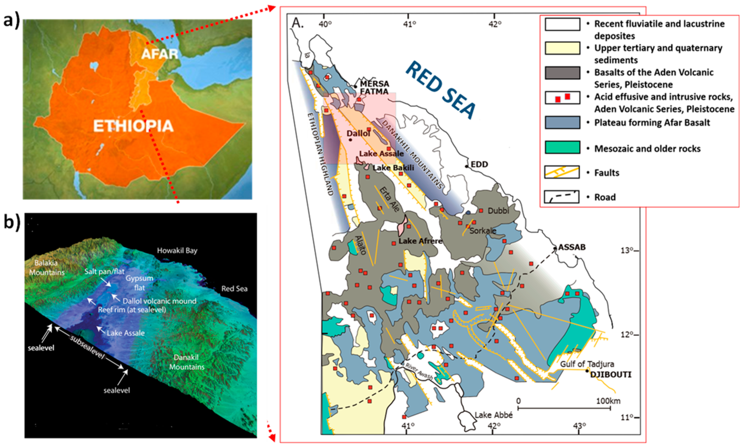
  • Natural salt lakes: Lake Karum, which is located in the northern part of the country (Afar region) in the geological depression termed “Denakil Depression”. Also, a mining settlement called “Dallol” is located in the north of Lake Karum. These kinds of salty sites can be a potential source of brine and hence SGP considering the huge availability of freshwater such as rivers and lakes in different parts of Ethiopia.
  • Brine solutions: Brine can be found in the waste stream of geothermal power production sites. There exist established geothermal sites in Ethiopia, for example, the Aluto-Langano geothermal power station which is the oldest one with a net power generation capacity of 7.3 MW, and prospective areas, for example, in the Afar depression. Coupling the SGP from hypersaline water from geothermal wells enables a unique synergy that increases the overall economic viability of geothermal power plants.
  • Saline groundwater and industrial wastewater: Such types of feed resources can also be exploited for SGP; however, they require exhaustive assessment to determine the SGP potential of such sources in the country.
(iv) Technologies for CO2 use which at the same time allow for storage of renewables. Although Ethiopia is not an industrialized country with little considerable emission of CO2, the country still relies heavily on waste and biomass which are the largest primary energy sources of the country (92.4% of total energy supply). Up to 80% of Ethiopians have no access to electricity for household purposes, hence they entirely depend on wood stoves, which is largely associated with CO2 emission. This along with its ambition to reach a carbon-neutral status by 2025, the country could also benefit from advancing various CO2 capture and use technologies. For instance, considering the country’s huge solar energy potential, the implementation of direct CO2 electroreduction technologies driven by solar energy is among the alternative contributing to strategies of transforming the country into a carbon-neutral economy.

Author Contributions

Conceptualization, A.T.B., R.A.T., M.T.T. and A.Y.G.; writing—original draft preparation, A.T.B., R.A.T., M.T.T. and G.A.T.; writing—review and editing, A.T.B., R.A.T., A.A. and A.Y.G.; All authors have read and agreed to the published version of the manuscript.

Funding

No funding is provided for this work.

Acknowledgments

The authors are grateful to the work facilities provided by Jigjiga University (Ethiopia) and Technical University of Denmark (Denmark). G.A.Tiruye acknowledges the financial support from the Addis Ababa University through the thematic project (Refe. No_ VPRTT/PY-026/2018/10).

Conflicts of Interest

The authors declare no conflict of interest.

References

  1. EIA. Today in Energy. Available online: https://www.eia.gov/todayinenergy/detail.php?id=41433 (accessed on 14 October 2020).
  2. IEA. Key World Energy Statistics. 2020. Available online: https://www.iea.org/reports/key-world-energy-statistics-2020 (accessed on 14 October 2020).
  3. Tufa, R.A.; Curcio, E.; Fontananova, E.; Di Profio, G. 3.8 Membrane-Based Processes for Sustainable Power Generation Using Water: Pressure-Retarded Osmosis (PRO), Reverse Electrodialysis (RED), and Capacitive Mixing (CAPMIX). Compr. Membr. Sci. Eng. 2017, 2, 206–248. [Google Scholar]
  4. Tufa, R.A.; Pawlowski, S.; Veerman, J.; Bouzek, K.; Fontananova, E.; di Profio, G.; Velizarov, S.; Crespo, J.G.; Nijmeijer, K.; Curcio, E. Progress and prospects in reverse electrodialysis for salinity gradient energy conversion and storage. Appl. Energy 2018, 225, 290–331. [Google Scholar] [CrossRef]
  5. Lee, H.; Yanilmaz, M.; Toprakci, O.; Fu, K.; Zhang, X. A review of recent developments in membrane separators for rechargeable lithium-ion batteries. Energy Environ. Sci. 2014, 7, 3857–3886. [Google Scholar] [CrossRef]
  6. Liang, P.; Duan, R.; Jiang, Y.; Zhang, X.; Qiu, Y.; Huang, X. One-year operation of 1000-L modularized microbial fuel cell for municipal wastewater treatment. Water Res. 2018, 141, 1–8. [Google Scholar] [CrossRef] [PubMed]
  7. Chen, Z.; Higgins, D.; Yu, A.; Zhang, L.; Zhang, J. A review on non-precious metal electrocatalysts for PEM fuel cells. Energy Environ. Sci. 2011, 4, 3167–3192. [Google Scholar] [CrossRef]
  8. Pan, Z.; An, L.; Zhao, T.; Tang, Z. Advances and challenges in alkaline anion exchange membrane fuel cells. Prog. Energy Combust. Sci. 2018, 66, 141–175. [Google Scholar] [CrossRef]
  9. Tufa, R.A.; Chandac, D.; Tundisa, L.; Hnátb, J.; Bouzekb, K.; Veermand, J.; Fontananovae, E.; Di Profioe, G.; Curcioa, E. Salinity gradient power driven water electrolysis for hydrogen production. Chem. Eng. 2017, 60. Available online: https://www.google.com.hk/url?sa=t&rct=j&q=&esrc=s&source=web&cd=&ved=2ahUKEwiUiM-lhtTsAhVSBKYKHS8HCPAQFjAAegQIAhAC&url=https%3A%2F%2Fwww.aidic.it%2Fcet%2F17%2F60%2F048.pdf&usg=AOvVaw17Y5SPXwcteB66mGQc44wS (accessed on 3 October 2020).
  10. Tufa, R.A.; Hnát, J.; Němeček, M.; Kodým, R.; Curcio, E.; Bouzek, K. Hydrogen production from industrial wastewaters: An integrated reverse electrodialysis-Water electrolysis energy system. J. Clean. Prod. 2018, 203, 418–426. [Google Scholar] [CrossRef]
  11. Yin, H.; Yip, A.C. A review on the production and purification of biomass-derived hydrogen using emerging membrane technologies. Catalysts 2017, 7, 297. [Google Scholar] [CrossRef] [Green Version]
  12. Wang, Y.; Zhao, L.; Otto, A.; Robinius, M.; Stolten, D. A Review of Post-combustion CO2 Capture Technologies from Coal-fired Power Plants. Energy Procedia 2017, 114, 650–665. [Google Scholar] [CrossRef]
  13. Bank, W. Access to Electricity, Urban (% of Urban Population)—Ethiopia. 2018. Available online: https://data.worldbank.org/indicator/EG.ELC.RNWX.KH?locations=ET (accessed on 10 September 2020).
  14. Gabaldon Moreno, A. Renewables-Driven Membrane Distillation for Drinking Water Purification: Main Ethiopian Rift Valley Case Study. Master’s Thesis, School of Industrial Engineering and Management, Stockholm, Sweden, 2018. [Google Scholar]
  15. Issa, M. Energy Report—Ethiopia; Embassy of Sweden: Addis Abeba, Ethiopia, 2016. [Google Scholar]
  16. Beyene, G.; Kumie, A.; Edwards, R.; Troncoso, K. Opportunities for Transition To Clean Household Energy in Ethiopia: Application of the Household Energy Assessment Rapid Tool (HEART); World Health Organization: Geneva, Switzerland, 2018. [Google Scholar]
  17. Mondal, M.A.H.; Bryan, E.; Ringler, C.; Mekonnen, D.; Rosegrant, M.J.E. Ethiopian energy status and demand scenarios: Prospects to improve energy efficiency and mitigate GHG emissions. Energy 2018, 149, 161–172. [Google Scholar] [CrossRef]
  18. Cassia, R.; Nocioni, M.; Correa-Aragunde, N.; Lamattina, L. Climate change and the impact of greenhouse gasses: CO2 and NO, friends and foes of plant oxidative stress. Front. Plant Sci. 2018, 9, 273. [Google Scholar] [CrossRef] [PubMed]
  19. AEP. Ethiopia: Lotus Energy to Install Power Plant (500 MW) for Effort Group. Available online: https://africa-energy-portal.org/news/ethiopia-lotus-energy-install-power-plant-500-mw-effort-group (accessed on 25 September 2020).
  20. Multiconsult. Metahara 100 MW Solar PV Power Plant in Ethiopia. Available online: https://www.multiconsultgroup.com/projects/metahara-solar-pv-plant-ethiopia/ (accessed on 21 August 2020).
  21. Bank, W. Federal Democratic Republic of Ethiopia Ethiopia Electrification Program; 119032-ET; Government of Ethiopia: Addis Abeba, Ethiopia, 2018. Available online: www.documents.worldbank.org (accessed on 10 September 2020).
  22. Federal Democratic Republic of Ethiopia Ministry of Water and Energy. Scaling-Up Renewable Energy Program Ethiopia Investment Plan (Draft Final); Federal Democratic Republic of Ethiopia Ministry of Water and Energy: Addis Ababa, Ethiopia, 2012.
  23. Kirubakaran, A.; Jain, S.; Nema, R.K. A review on fuel cell technologies and power electronic interface. Renew. Sustain. Energy Rev. 2009, 13, 2430–2440. [Google Scholar] [CrossRef]
  24. Stephen, A.J.; Rees, N.V.; Mikheenko, I.; Macaskie, L.E. Platinum and Palladium Bio-Synthesized Nanoparticles as Sustainable Fuel Cell Catalysts. Front. Energy Res. 2019, 7. [Google Scholar] [CrossRef] [Green Version]
  25. Samimi, F.; Rahimpour, M.R. Chapter 14—Direct Methanol Fuel Cell. In Methanol; Basile, A., Dalena, F., Eds.; Elsevier: Amsterdam, The Netherlands, 2018; pp. 381–397. [Google Scholar] [CrossRef]
  26. Logan, B.E.; Hamelers, B.; Rozendal, R.; Schröder, U.; Keller, J.; Freguia, S.; Aelterman, P.; Verstraete, W.; Rabaey, K. Microbial Fuel Cells: Methodology and Technology. Environ. Sci. Technol. 2006, 40, 5181–5192. [Google Scholar] [CrossRef]
  27. Potter, M.C. Electrical effects accompanying the decomposition of organic compounds. Proc. R. Soc. London. Ser. Bcontaining Pap. A Biol. Character 1911, 84, 260–276. [Google Scholar]
  28. Pant, D.; Van Bogaert, G.; Diels, L.; Vanbroekhoven, K. A review of the substrates used in microbial fuel cells (MFCs) for sustainable energy production. Bioresour. Technol. 2010, 101, 1533–1543. [Google Scholar] [CrossRef]
  29. Zhou, M.; Wang, H.; Hassett, D.J.; Gu, T. Recent advances in microbial fuel cells (MFCs) and microbial electrolysis cells (MECs) for wastewater treatment, bioenergy and bioproducts. J. Chem. Technol. Biotechnol. 2013, 88, 508–518. [Google Scholar] [CrossRef]
  30. Rabaey, K.; Boon, N.; Höfte, M.; Verstraete, W. Microbial Phenazine Production Enhances Electron Transfer in Biofuel Cells. Environ. Sci. Technol. 2005, 39, 3401–3408. [Google Scholar] [CrossRef]
  31. Logan, B.E.; Regan, J.M. Microbial Fuel Cells—Challenges and Applications. Environ. Sci. Technol. 2006, 40, 5172–5180. [Google Scholar] [CrossRef] [Green Version]
  32. Mekuto, L.; Olowolafe, A.V.; Pandit, S.; Dyantyi, N.; Nomngongo, P.; Huberts, R. Microalgae as a biocathode and feedstock in anode chamber for a self-sustainable microbial fuel cell technology: A review. South Afr. J. Chem. Eng. 2020, 31, 7–16. [Google Scholar] [CrossRef]
  33. Schröder, U. Anodic electron transfer mechanisms in microbial fuel cells and their energy efficiency. Phys. Chem. Chem. Phys. 2007, 9, 2619–2629. [Google Scholar] [CrossRef] [PubMed]
  34. Santoro, C.; Arbizzani, C.; Erable, B.; Ieropoulos, I. Microbial fuel cells: From fundamentals to applications. A review. J. Power Sources 2017, 356, 225–244. [Google Scholar] [CrossRef]
  35. Peng, L.; You, S.-J.; Wang, J.-Y. Carbon nanotubes as electrode modifier promoting direct electron transfer from Shewanella oneidensis. Biosens. Bioelectron. 2010, 25, 1248–1251. [Google Scholar] [CrossRef] [PubMed]
  36. Freguia, S.; Masuda, M.; Tsujimura, S.; Kano, K. Lactococcus lactis catalyses electricity generation at microbial fuel cell anodes via excretion of a soluble quinone. Bioelectrochemistry 2009, 76, 14–18. [Google Scholar] [CrossRef]
  37. Keck, A.; Conradt, D.; Mahler, A.; Stolz, A.; Mattes, R.; Klein, J. Identification and functional analysis of the genes for naphthalenesulfonate catabolism by Sphingomonas xenophaga BN6. Microbiology 2006, 152, 1929–1940. [Google Scholar] [CrossRef] [PubMed] [Green Version]
  38. Deng, L.; Li, F.; Zhou, S.; Huang, D.; Ni, J. A study of electron-shuttle mechanism in Klebsiella pneumoniae based-microbial fuel cells. Chin. Sci. Bull. 2010, 55, 99–104. [Google Scholar] [CrossRef]
  39. Gude, V.G. Wastewater treatment in microbial fuel cells—An overview. J. Clean. Prod. 2016, 122, 287–307. [Google Scholar] [CrossRef]
  40. Logan, B.E.; Rabaey, K. Conversion of Wastes into Bioelectricity and Chemicals by Using Microbial Electrochemical Technologies. Science 2012, 337, 686–690. [Google Scholar] [CrossRef] [PubMed] [Green Version]
  41. Rozendal, R.A.; Hamelers, H.V.M.; Rabaey, K.; Keller, J.; Buisman, C.J.N. Towards practical implementation of bioelectrochemical wastewater treatment. Trends Biotechnol. 2008, 26, 450–459. [Google Scholar] [CrossRef] [PubMed]
  42. Choi, J.; Ahn, Y. Continuous electricity generation in stacked air cathode microbial fuel cell treating domestic wastewater. J. Environ. Manag. 2013, 130, 146–152. [Google Scholar] [CrossRef] [PubMed]
  43. Puig, S.; Serra, M.; Coma, M.; Balaguer, M.D.; Colprim, J. Simultaneous domestic wastewater treatment and renewable energy production using microbial fuel cells (MFCs). Water Sci. Technol. 2011, 64, 904–909. [Google Scholar] [CrossRef] [PubMed]
  44. Yokoyama, H.; Ohmori, H.; Ishida, M.; Waki, M.; Tanaka, Y. Treatment of cow-waste slurry by a microbial fuel cell and the properties of the treated slurry as a liquid manure. Anim. Sci. J. 2006, 77, 634–638. [Google Scholar] [CrossRef]
  45. Sathian, S.; Rajasimman, M.; Radha, G.; Shanmugapriya, V.; Karthikeyan, C. Performance of SBR for the treatment of textile dye wastewater: Optimization and kinetic studies. Alex. Eng. J. 2014, 53, 417–426. [Google Scholar] [CrossRef] [Green Version]
  46. Zhong, C.; Zhang, B.; Kong, L.; Xue, A.; Ni, J. Electricity generation from molasses wastewater by an anaerobic baffled stacking microbial fuel cell. J. Chem. Technol. Biotechnol. 2011, 86, 406–413. [Google Scholar] [CrossRef]
  47. Habermann, W.; Pommer, E.H. Biological fuel cells with sulphide storage capacity. Appl. Microbiol. Biotechnol. 1991, 35, 128–133. [Google Scholar] [CrossRef]
  48. Water, A.A.; Authority, S. Environmental and Social Impact Assessment of the Wastewater Treatment Plant and Sewer Lines Expansion and Rehabilitation in The Kaliti Catchment; Addis Ababa Water and Sewerage Authority (AAWSA)Water, Sanitation Rehabilitation and Development Project Office: Addis Ababa, Ethiopia, 2014.
  49. Fikreyesus, D.; Turpeinen, M.; Gebre, G.; Nebsu, B.; Ermias, M. Ethiopia Solid Waste & Landfill, Country Profile and Action Plan Report; Global Methane Initiative: Washington, DC, USA, 2011. [Google Scholar]
  50. Wu, S.; Li, H.; Zhou, X.; Liang, P.; Zhang, X.; Jiang, Y.; Huang, X. A novel pilot-scale stacked microbial fuel cell for efficient electricity generation and wastewater treatment. Water Res. 2016, 98, 396–403. [Google Scholar] [CrossRef]
  51. Kuntke, P.; Śmiech, K.M.; Bruning, H.; Zeeman, G.; Saakes, M.; Sleutels, T.H.J.A.; Hamelers, H.V.M.; Buisman, C.J.N. Ammonium recovery and energy production from urine by a microbial fuel cell. Water Res. 2012, 46, 2627–2636. [Google Scholar] [CrossRef]
  52. Jiang, Y.; Yang, X.; Liang, P.; Liu, P.; Huang, X. Microbial fuel cell sensors for water quality early warning systems: Fundamentals, signal resolution, optimization and future challenges. Renew. Sustain. Energy Rev. 2018, 81, 292–305. [Google Scholar] [CrossRef]
  53. Ge, Z.; Zhang, F.; Grimaud, J.; Hurst, J.; He, Z. Long-term investigation of microbial fuel cells treating primary sludge or digested sludge. Bioresour. Technol. 2013, 136, 509–514. [Google Scholar] [CrossRef]
  54. Zhang, F.; Ge, Z.; Grimaud, J.; Hurst, J.; He, Z. In situ investigation of tubular microbial fuel cells deployed in an aeration tank at a municipal wastewater treatment plant. Bioresour. Technol. 2013, 136, 316–321. [Google Scholar] [CrossRef]
  55. Zhang, F.; Ge, Z.; Grimaud, J.; Hurst, J.; He, Z. Long-Term Performance of Liter-Scale Microbial Fuel Cells Treating Primary Effluent Installed in a Municipal Wastewater Treatment Facility. Environ. Sci. Technol. 2013, 47, 4941–4948. [Google Scholar] [CrossRef] [PubMed]
  56. Miller, H.A.; Bouzek, K.; Hnat, J.; Loos, S.; Bernäcker, C.I.; Weißgärber, T.; Röntzsch, L.; Meier-Haack, J. Green hydrogen from anion exchange membrane water electrolysis: A review of recent developments in critical materials and operating conditions. Sustain. Energy Fuels 2020, 4, 2114–2133. [Google Scholar] [CrossRef]
  57. Badwal, S.P.; Giddey, S.S.; Munnings, C.; Bhatt, A.I.; Hollenkamp, A.F. Emerging electrochemical energy conversion and storage technologies. Front. Chem. 2014, 2, 79. [Google Scholar] [CrossRef] [PubMed] [Green Version]
  58. Rashid, M.M.; Al Mesfer, M.K.; Naseem, H.; Danish, M. Hydrogen production by water electrolysis: A review of alkaline water electrolysis, PEM water electrolysis and high temperature water electrolysis. Int. J. Eng. Adv. Technol 2015, 4, 2249–8958. [Google Scholar]
  59. Wang, M.; Wang, Z.; Gong, X.; Guo, Z. The intensification technologies to water electrolysis for hydrogen production–A review. Renew. Sustain. Energy Rev. 2014, 29, 573–588. [Google Scholar] [CrossRef]
  60. Holladay, J.D.; Hu, J.; King, D.L.; Wang, Y. An overview of hydrogen production technologies. Catal. Today 2009, 139, 244–260. [Google Scholar] [CrossRef]
  61. Gabisa, E.W.; Gheewala, S.H. Potential of bio-energy production in Ethiopia based on available biomass residues. Biomass Bioenergy 2018, 111, 77–87. [Google Scholar] [CrossRef]
  62. Kaygusuz, K. Energy for sustainable development: A case of developing countries. Renew. Sustain. Energy Rev. 2012, 16, 1116–1126. [Google Scholar] [CrossRef]
  63. Guta, D.D. Assessment of biomass fuel resource potential and utilization in Ethiopia: Sourcing strategies for renewable energies. Int. J. Renew. Energy Res. 2012, 2, 131–139. [Google Scholar]
  64. Brackish Water Desalination System; Afar Region, Ethiopia, Unpublished; 2008.
  65. Sołowski, G.; Shalaby, M.S.; Abdallah, H.; Shaban, A.M.; Cenian, A. Production of hydrogen from biomass and its separation using membrane technology. Renew. Sustain. Energy Rev. 2018, 82, 3152–3167. [Google Scholar] [CrossRef]
  66. UNEP. In Sustainability of Biogas and Solid Biomass Value Chains in Ethiopia; Technical Report; UNEP: Nairobi, Kenya, 2018.
  67. Mei, Y.; Tang, C.Y. Recent developments and future perspectives of reverse electrodialysis technology: A review. Desalination 2018, 425, 156–174. [Google Scholar] [CrossRef]
  68. Vermaas, D.A.; Saakes, M.; Nijmeijer, K. Doubled Power Density from Salinity Gradients at Reduced Intermembrane Distance. Environ. Sci. Technol. 2011, 45, 7089–7095. [Google Scholar] [CrossRef]
  69. Besha, A.T.; Tsehaye, M.T.; Aili, D.; Zhang, W.; Tufa, R.A. Design of Monovalent Ion Selective Membranes for Reducing the Impacts of Multivalent Ions in Reverse Electrodialysis. Membranes 2020, 10, 7. [Google Scholar] [CrossRef] [Green Version]
  70. Avci, A.H.; Sarkar, P.; Tufa, R.A.; Messana, D.; Argurio, P.; Fontananova, E.; Di Profio, G.; Curcio, E. Effect of Mg2+ ions on energy generation by Reverse Electrodialysis. J. Membr. Sci. 2016, 520, 499–506. [Google Scholar] [CrossRef]
  71. Tufa, R.A.; Chanda, D.; Tundis, L.; Hnát, J.; Bouzek, K.; Veerman, J.; Fontananova, E.; Di Profio, G.; Curcio, E. Salinity gradient power driven water electrolysis for hydrogen production. Chem. Eng. Trans. 2017, 60, 283–288. [Google Scholar] [CrossRef]
  72. Hatzell, M.C.; Ivanov, I.; Cusick, R.D.; Zhu, X.; Logan, B.E. Comparison of hydrogen production and electrical power generation for energy capture in closed-loop ammonium bicarbonate reverse electrodialysis systems. Phys. Chem. Chem. Phys. 2014, 16, 1632–1638. [Google Scholar] [CrossRef]
  73. Tedesco, M.; Scalici, C.; Vaccari, D.; Cipollina, A.; Tamburini, A.; Micale, G. Performance of the first reverse electrodialysis pilot plant for power production from saline waters and concentrated brines. J. Membr. Sci. 2016, 500, 33–45. [Google Scholar] [CrossRef] [Green Version]
  74. Tufa, R.A.; Curcio, E.; Brauns, E.; van Baak, W.; Fontananova, E.; Di Profio, G. Membrane distillation and reverse electrodialysis for near-zero liquid discharge and low energy seawater desalination. J. Membr. Sci. 2015, 496, 325–333. [Google Scholar] [CrossRef]
  75. Kim, Y.; Logan, B.E. Hydrogen production from inexhaustible supplies of fresh and salt water using microbial reverse-electrodialysis electrolysis cells. Proc. Natl. Acad. Sci. USA 2011, 108, 16176–16181. [Google Scholar] [CrossRef] [Green Version]
  76. Tufa, R.A.; Rugiero, E.; Chanda, D.; Hnàt, J.; van Baak, W.; Veerman, J.; Fontananova, E.; Di Profio, G.; Drioli, E.; Bouzek, K.; et al. Salinity gradient power-reverse electrodialysis and alkaline polymer electrolyte water electrolysis for hydrogen production. J. Membr. Sci. 2016, 514, 155–164. [Google Scholar] [CrossRef]
  77. Kingsbury, R.S.; Chu, K.; Coronell, O. Energy storage by reversible electrodialysis: The concentration battery. J. Membr. Sci. 2015, 495, 502–516. [Google Scholar] [CrossRef]
  78. Loeb, S.; Van Hessen, F.; Shahaf, D. Production of energy from concentrated brines by pressure-retarded osmosis: II. Experimental results and projected energy costs. J. Membr. Sci. 1976, 1, 249–269. [Google Scholar] [CrossRef]
  79. Loeb, S. Method and Apparatus for Generating Power Utilizing Pressure-Retarded-Osmosis. U.S. Patent 3,9062,50A, 16 September 1975. [Google Scholar]
  80. Mehta, G.D. Further results on the performance of present-day osmotic membranes in various osmotic regions. J. Membr. Sci. 1982, 10, 3–19. [Google Scholar] [CrossRef]
  81. Lee, K.L.; Baker, R.W.; Lonsdale, H.K. Membranes for power generation by pressure-retarded osmosis. J. Membr. Sci. 1981, 8, 141–171. [Google Scholar] [CrossRef]
  82. Aaberg, R.J. Osmotic power: A new and powerful renewable energy source? Refocus 2003, 4, 48–50. [Google Scholar] [CrossRef]
  83. Thorsen, T.; Holt, T. Finding hidden energy in membrane processes. Filtr. Sep. 2005, 42, 28–30. [Google Scholar] [CrossRef]
  84. Achilli, A.; Childress, A.E. Pressure retarded osmosis: From the vision of Sidney Loeb to the first prototype installation—Review. Desalination 2010, 261, 205–211. [Google Scholar] [CrossRef]
  85. ForwardOsmosisTech. Inquiry about Commercially Available PRO Membranes. Available online: https://www.forwardosmosistech.com/inquiry-about-commercially-available-pro-membranes/ (accessed on 21 October 2020).
  86. Logan, B.E.; Elimelech, M. Membrane-based processes for sustainable power generation using water. Nature 2012, 488, 313–319. [Google Scholar] [CrossRef]
  87. Gebreyohannes, A.Y.; Curcio, E.; Poerio, T.; Mazzei, R.; Di Profio, G.; Drioli, E.; Giorno, L. Treatment of Olive Mill Wastewater by Forward Osmosis. Sep. Purif. Technol. 2015, 147, 292–302. [Google Scholar] [CrossRef]
  88. Sarp, S.; Li, Z.; Saththasivam, J. Pressure Retarded Osmosis (PRO): Past experiences, current developments, and future prospects. Desalination 2016, 389, 2–14. [Google Scholar] [CrossRef]
  89. Cavalazzi, B.; Barbieri, R.; Gómez, F.; Capaccioni, B.; Olsson-Francis, K.; Pondrelli, M.; Rossi, A.; Hickman-Lewis, K.; Agangi, A.; Gasparotto, G.J.A. The Dallol geothermal area, Northern Afar (Ethiopia)—An exceptional planetary field analog on Earth. Astrobiology 2019, 19, 553–578. [Google Scholar] [CrossRef]
  90. Feyissa, D. The political economy of salt in the Afar Regional State in northeast Ethiopia. Rev. Afr. Political Econ. 2011, 38, 7–21. [Google Scholar] [CrossRef]
  91. Warren, J.K. Danakhil Potash, Ethiopia: Is the Present Geology the Key? SaltWork Consultants: Seacliff Park, Australia, 2015. [Google Scholar]
  92. Wei, P.; Cheng, L.-H.; Zhang, L.; Xu, X.-H.; Chen, H.-L.; Gao, C.-J. A review of membrane technology for bioethanol production. Renew. Sustain. Energy Rev. 2014, 30, 388–400. [Google Scholar] [CrossRef]
  93. Basile, A.; Gugliuzza, A.; Iulianelli, A.; Morrone, P. Membrane technology for carbon dioxide (CO2) capture in power plants. In Advanced Membrane Science and Technology for Sustainable Energy and Environmental Applications; Elsevier: Amsterdam, The Netherlands, 2011; pp. 113–159. [Google Scholar]
  94. Curcio, S. Membranes for advanced biofuels production. In Advanced Membrane Science and Technology for Sustainable Energy and Environmental Applications; Elsevier: Amsterdam, The Netherlands, 2011; pp. 361–410. [Google Scholar]
  95. Mazzei, R.; Piacentini, E.; Yihdego Gebreyohannes, A.; Giorno, L. Membrane bioreactors in food, pharmaceutical and biofuel applications: State of the art, progresses and perspectives. Curr. Org. Chem. 2017, 21, 1671–1701. [Google Scholar] [CrossRef]
  96. Gebreyohannes, A.Y.; Mazzei, R.; Curcio, E.; Poerio, T.; Drioli, E.; Giorno, L. Study on the in situ enzymatic self-cleansing of microfiltration membrane for valorization of olive mill wastewater. Ind. Eng. Chem. Res. 2013, 52, 10396–10405. [Google Scholar] [CrossRef]
  97. Giorno, L.; Drioli, E. Biocatalytic membrane reactors: Applications and perspectives. Trends Biotechnol. 2000, 18, 339–349. [Google Scholar] [CrossRef]
  98. Naik, S.N.; Goud, V.V.; Rout, P.K.; Dalai, A.K. Production of first and second generation biofuels: A comprehensive review. Renew. Sustain. Energy Rev. 2010, 14, 578–597. [Google Scholar] [CrossRef]
  99. Gebreyohannes, A.Y.; Bilad, M.R.; Verbiest, T.; Courtin, C.M.; Dornez, E.; Giorno, L.; Curcio, E.; Vankelecom, I.F.J. Nanoscale tuning of enzyme localization for enhanced reactor performance in a novel magnetic-responsive biocatalytic membrane reactor. J. Membr. Sci. 2015, 487, 209–220. [Google Scholar] [CrossRef]
  100. Gebreyohannes, A.Y.; Dharmjeet, M.; Swusten, T.; Mertens, M.; Verspreet, J.; Verbiest, T.; Courtin, C.M.; Vankelecom, I.F.J. Simultaneous glucose production from cellulose and fouling reduction using a magnetic responsive membrane reactor with superparamagnetic nanoparticles carrying cellulolytic enzymes. Bioresour. Technol. 2018, 263, 532–540. [Google Scholar] [CrossRef]
  101. Mahboubi, A.; Ylitervo, P.; Doyen, W.; De Wever, H.; Taherzadeh, M.J. Reverse membrane bioreactor: Introduction to a new technology for biofuel production. Biotechnol. Adv. 2016, 34, 954–975. [Google Scholar] [CrossRef] [Green Version]
  102. Le, N.L.; Nunes, S.P. Materials and membrane technologies for water and energy sustainability. Sustain. Mater. Technol. 2016, 7, 1–28. [Google Scholar] [CrossRef] [Green Version]
  103. Wang, W.; Luo, Q.; Li, B.; Wei, X.; Li, L.; Yang, Z. Recent progress in redox flow battery research and development. Adv. Funct. Mater. 2013, 23, 970–986. [Google Scholar] [CrossRef]
  104. Soloveichik, G.L. Flow batteries: Current status and trends. Chem. Rev. 2015, 115, 11533–11558. [Google Scholar] [CrossRef] [PubMed]
  105. Olabi, A.G. Renewable energy and energy storage systems. Energy 2017, 136, 1–6. [Google Scholar] [CrossRef]
  106. Guney, M.S.; Tepe, Y. Classification and assessment of energy storage systems. Renew. Sustain. Energy Rev. 2017, 75, 1187–1197. [Google Scholar] [CrossRef]
  107. Amrouche, S.O.; Rekioua, D.; Rekioua, T.; Bacha, S. Overview of energy storage in renewable energy systems. Int. J. Hydrogen Energy 2016, 41, 20914–20927. [Google Scholar] [CrossRef]
  108. Associates, M. Overview of Energy Storage Methods; Mora Associates Ltd.: Aéroport Strasbourg, France, 2007. [Google Scholar]
  109. May, G.J.; Davidson, A.; Monahov, B. Lead batteries for utility energy storage: A review. J. Energy Storage 2018, 15, 145–157. [Google Scholar] [CrossRef]
  110. Battery Separators—Types and Importance in the Performance of Battery. Available online: https://components101.com/articles/battery-seperators-types-and-importance (accessed on 25 June 2020).
  111. Roy, P.; Srivastava, S.K. Nanomaterials for Electrochemical Energy Storage Devices; Wiley Online Library: Hoboken, NJ, USA, 2019. [Google Scholar]
  112. Tsehaye, M.T.; Alloin, F.; Iojoiu, C. Prospects for Anion-Exchange Membranes in Alkali Metal–Air Batteries. Energies 2019, 12, 4702. [Google Scholar] [CrossRef] [Green Version]
  113. Sum, E.; Rychcik, M.; Skyllas-kazacos, M. Investigation of the V(V)/V(IV) system for use in the positive half-cell of a redox battery. J. Power Sources 1985, 16, 85–95. [Google Scholar] [CrossRef]
  114. Cha, S.-H. Recent development of nanocomposite membranes for vanadium redox flow batteries. J. Nanomater. 2015, 2015, 207525. [Google Scholar] [CrossRef] [Green Version]
  115. Li, X.; Zhang, H.; Mai, Z.; Zhang, H.; Vankelecom, I. Ion exchange membranes for vanadium redox flow battery (VRB) applications. Energy Environ. Sci. 2011, 4, 1147–1160. [Google Scholar] [CrossRef]
  116. Gierke, T.D.; Munn, G.; Wilson, F. The morphology in nafion perfluorinated membrane products, as determined by wide-and small-angle X-ray studies. J. Polym. Sci. Polym. Phys. Ed. 1981, 19, 1687–1704. [Google Scholar] [CrossRef]
  117. Xi, J.; Wu, Z.; Qiu, X.; Chen, L. Nafion/SiO2 hybrid membrane for vanadium redox flow battery. J. Power Sources 2007, 166, 531–536. [Google Scholar] [CrossRef]
  118. Schulte, D.; Drillkens, J.; Schulte, B.; Sauer, D. Nafion hybrid membranes for use in redox flow batteries. J. Electrochem. Soc. 2010, 157, A989. [Google Scholar] [CrossRef]
  119. Dai, W.; Yu, L.; Li, Z.; Yan, J.; Liu, L.; Xi, J.; Qiu, X. Sulfonated poly (ether ether ketone)/graphene composite membrane for vanadium redox flow battery. Electrochim. Acta 2014, 132, 200–207. [Google Scholar] [CrossRef]
  120. Schwenzer, B.; Zhang, J.; Kim, S.; Li, L.; Liu, J.; Yang, Z. Membrane development for vanadium redox flow batteries. ChemSusChem 2011, 4, 1388–1406. [Google Scholar] [CrossRef]
  121. Hu, B.; Seefeldt, C.; DeBruler, C.; Liu, T.L. Boosting the energy efficiency and power performance of neutral aqueous organic redox flow batteries. J. Mater. Chem. A 2017, 5, 22137–22145. [Google Scholar] [CrossRef]
  122. Li, Y.; Liu, Y.; Xu, Z.; Yang, Z. Poly (phenylene oxide)-Based Ion-Exchange Membranes for Aqueous Organic Redox Flow Battery. Ind. Eng. Chem. Res. 2019, 58, 10707–10712. [Google Scholar] [CrossRef]
  123. Janoschka, T.; Martin, N.; Martin, U.; Friebe, C.; Morgenstern, S.; Hiller, H.; Hager, M.D.; Schubert, U.S. An aqueous, polymer-based redox-flow battery using non-corrosive, safe, and low-cost materials. Nature 2015, 527, 78–81. [Google Scholar] [CrossRef]
  124. Wei, X.; Pan, W.; Duan, W.; Hollas, A.; Yang, Z.; Li, B.; Nie, Z.; Liu, J.; Reed, D.; Wang, W. Materials and systems for organic redox flow batteries: Status and challenges. Acs Energy Lett. 2017, 2, 2187–2204. [Google Scholar] [CrossRef]
  125. Chen, H.; Cong, G.; Lu, Y.-C. Recent progress in organic redox flow batteries: Active materials, electrolytes and membranes. J. Energy Chem. 2018, 27, 1304–1325. [Google Scholar] [CrossRef] [Green Version]
  126. Wong, S. Building Capacity for CO2 Capture and Storage in the APEC Region; Asia-Pacific Economic Cooperation: Singapore, 2009. [Google Scholar]
  127. Bui, M.; Adjiman, C.S.; Bardow, A.; Anthony, E.J.; Boston, A.; Brown, S.; Fennell, P.S.; Fuss, S.; Galindo, A.; Hackett, L.A.; et al. Carbon capture and storage (CCS): The way forward. Energy Environ. Sci. 2018, 11, 1062–1176. [Google Scholar] [CrossRef] [Green Version]
Figure 1. The share of electricity production in Ethiopia.
Sustainability 12 08792 g001
Figure 2. Schematic representation of fuel cell using hydrogen as a fuel [24].
Sustainability 12 08792 g002
Figure 3. (a) A bacterium in the anode chamber transfers electrons produced from an electron donor (glucose) to the anode electrode [26], (b) electron transfer mechanisms in MFC [32].
Sustainability 12 08792 g003
Figure 4. MFC for different sources of wastewater treatment: anode chamber can be fed with various wastewater sources while the cathode chamber can be used to produce useful chemicals or remove environmental pollutants [39].
Sustainability 12 08792 g004
Figure 5. Energy production from wastewater using MFC through different options [39].
Sustainability 12 08792 g005
Figure 6. (a) Water electrolysis cells, proton exchange membrane and (b) alkaline electrolysis.
Sustainability 12 08792 g006
Figure 7. The concept of hydrogen production from renewable energy power sources for distributed power generation [57].
Sustainability 12 08792 g007
Figure 8. Hydrogen production from biomass by pyrolysis and gasification and subsequent membrane filtration.
Sustainability 12 08792 g008
Figure 9. Schematic illustration of RED stack. Three alternative ion-exchange membrane (IEM) contribute a single “cell”; however, a large number of cells are required to produce large-scale power [3].
Sustainability 12 08792 g009
Figure 10. Illustration of the PRO system for SGP production [85].
Sustainability 12 08792 g010
Figure 11. (a) Afar region in Ethiopia: Dallol depression, its location and geological features of the Dallol saline pan; (b) 3D Digital Elevation Model (DEM) overlay image of Danakil Depression: the color transition from green to blue shading indicates above and below sea level [91].
Sustainability 12 08792 g011
Figure 12. Process steps in biofuel production from biomass using membrane technology.
Sustainability 12 08792 g012
Figure 13. Schematic view of a redox flow battery system [124].
Sustainability 12 08792 g013
Figure 14. A spiral wound module for separating CO2 from other gases [126]. Pressurized feed gas pumped into the membrane module. A stream of higher CO2 concentration is gained from the permeate side. The other gases are called retentate. Vacuum pump or compressors (not shown in this figure) are used to increase the partial pressure of the CO2 gas.
Sustainability 12 08792 g014
Table 1. Potential and exploited energy sources in Ethiopia [16,17].
SourcesUnitPotentialExploitedExploited (%)
HydropowerMW45,0003180~7
Solar (day)kWh/m25.2<1
Wind (power speed)GW m/s1350 > 7 a0.324<1
Geothermal MW70007.3<1
Wood Million T112056050
Agricultural wasteMillion T15–20~630
Natural gasTrillion m3 (2013)<0.100
CoalMillion T>3000
Oil ShaleMillion T2530
Bio-gasHouseholds1–3 million17 896<1
a Potential wind GW energy > 7 m/s, a measure of usable wind energy.
Table 2. Installed capacity of existing power plants in Ethiopia [15,19,20].
Power PlantsCapacity (MW)Operational SinceType
Aba Samuel 6.61932Hydropower
Koka43.21960Hydropower
Tis Abay I 11.41964Hydropower
Awash II321966Hydropower
Awash III321971Hydropower
Fincha 1341973/2003Hydropower
Melka Wakena1531998Hydropower
Alutto Langano7.31999Geothermal
Tis Abay II732001Hydropower
Gilgel Gibe I1842004Hydropower
Kaliti142004Diesel
Dire Dawa382004Diesel
Awash 7 kilo352004Diesel
Tekeze3002009Hydropower
Gilgel Gibe II4202010Hydropower
Beles4602010Hydropower
Adama I512010Wind
Fincha Amerti Neshi972011Hydropower
Ashegoda1202012Wind
Adama II1532015Wind
Gilgel Gibe III18702015Hydropower
Ayisha300Wind
Debre Birhan100Wind
Asela100Wind
Mesebo Harena42Wind
Galema I250Wind
Metahara100Solar
Gad and Dicheto250Solar
Tigray 500Solar
Table 3. Comparison of the different types of fuel cells.
Type of Fuel Cell (FC)ElectrolyteOperating Temperature (°C)Power OutputElectrical Efficiency (%)Applications AdvantagesDisadvantages
Polymer electrolyte membrane (PEMFC) * Solid organic polymer-Perfluoro sulfonic acid50–100<1 kW–250 kW53–58 (transportation)
25–35 (stationary)
Backup power
Portable power
Small distributed generation
Transportation
Reduced corrosion and electrolyte management problems
Low temperature
Quick start-up
Expensive catalyst
High sensitivity to fuel impurities
Waste heat temperature for combined heat and power (CHP)
Alkaline fuel cell (AFC)Aqueous solution of potassium hydroxide soaked in matrix90–10010 kW–100 kW60
Military
Space
Faster cathode reaction in alkaline electrolyte
Expensive removal of CO2 from fuel and air steams required (CO2 degrades the electrolytes)
Phosphoric acid fuel cell (PAFC)Liquid phosphoric acid soaked in a matrix150–20050 kW–1 MW (250 kW typical module)> 40
Distributed grid
High overall efficiency with CHP
High tolerance to impurities
Requires expensive Pt catalysts
Low current and power
Large size/weight
Molten carbonate fuel cell (MCFC)Liquid solution of Li2 CO3, Na2 CO3 and/or K2 CO3150–200<1 kW–1 MW (250 kW typical module)45–47
Electric utility
Low distributed generation
High efficiency
Fuel flexibility
Use of different catalysts
Suitable for CHP
High temperature speeds corrosion and breakdown of cell components
Complex electrolyte management
Slow start-up
Solid oxide fuel cell (SOFC)Yttria stabilized zirconia600–700<1 kW–3 MW35–40
Auxiliary power
Electric utility
Large distributed generation
High efficiency
Fuel flexibility
Utility of different catalysts
Low electrolyte management problems
Suitable for CHP
Hybrid/GT cycle
High temperature enhances corrosion and breakdown of cell components
Slow start-up
Brittleness of ceramic electrolytes with thermal cycling
* Includes direct methanol FC (DMFC) typically used for small portable power applications up to 100 W and operating at 60–90 °C.
Table 4. The main characteristics of hydrogen separation membranes [11].
Parameters *PolymericMicroporousDense *
Typical compositionPolyimide; Cellulose acetateSilica; Zeolites; Metal-organic frameworksPalladium;Palladium alloys
Separation mechanismSolution-diffusionMolecular-sievingSolution-diffusion
Driving force *Partial pressure differencePartial pressure differencePartial pressure difference
Operation temperature≤110 °C≤1000 °C150–700 °C
Relative permeabilityLow-moderateModerate- highLow
Typical selectivityModerateLow-moderateVery- high
Relative costLowLow-moderateModerate- high
* assumed ideal gas conditions.
Table 5. Experimental performance for laboratory size flat sheet and hollow fiber PRO membranes [88].
Draw Solution Concentration (M NaCl)Draw Solution Pressure (bar)MembranePower Density (W/m2)
0.609.7CTA flat sheet2.7
0.5913.0TFC flat sheet9.0
1.039.7CTA flat sheet4.0
1.0020.7TFC flat sheet14.1
1.0015.0TFC flat sheet12.0
1.06TFC flat sheet11.4
2.0712.6CTA falt sheet3.2
3.0048.0TFC flat sheet60.0
1.0015.0Dual layer hollow fiber5.1
1.0020.0TFC hollow fiber7.6
1.0015.0TFC hollow fiber16.5
1.0015.0TFC hollow fiber20.9
1.0020.0TFC hollow fiber24.0
Table 6. Classification of energy storage technologies [106,107,108].
Energy StorageWorking PrincipleTypical Examples
ChemicalEnergy is stored in the chemical bonds of atoms and molecules.Hydrogen, synthetic natural gas, biofuels and thermochemical energy storage.
ElectrochemicalConvert chemical energy into electrical energy. Energy available as electric current at a defined voltage and timeElectrochemical batteries (primary and secondary cell or battery) and electrochemical capacitors.
MechanicalConvert mechanical energy into electrical energy.Flywheel system, pumped hydro storage system and compressed air energy storage system.
Electrical Realized by applying supercapacitor and magnetic storage.Capacitor, supercapacitor and superconducting magnet.
ThermalStore thermal energy by heating/cooling different media in enclosures.Sensible heat system, latent heat system, absorption and adsorption system
Publisher’s Note: MDPI stays neutral with regard to jurisdictional claims in published maps and institutional affiliations.

