1. Introduction
The global shift toward sustainable transportation has driven a rapid increase in the adoption of electric vehicles (EVs) [
1,
2], motivated by their significant environmental benefits [
3,
4], including the reduction in greenhouse gas emissions and urban air pollution. As governments implement stricter emission regulations and consumers become more environmentally conscious, EVs are expected to play a central role in the decarbonization of the mobility sector. However, to support this transition on a large scale, the charging infrastructure must evolve accordingly. In particular, ultrafast charging is essential to reduce charging times and enhance user convenience, addressing one of the main barriers to EV adoption [
5].
Ultrafast charging is advancing rapidly, yet practical deployment is constrained by battery-side electrothermal limits that drive rapid temperature rise and accelerated degradation. These challenges make intelligent, health-aware, fast-charging strategies particularly relevant [
6].
Fast EV charging stations inherently demand high power, prompting a shift toward DC-based power distribution architectures optimized for the specific needs of fast-charging infrastructure. Meeting these demands requires technological innovation not only at the system level but also in critical components such as circuit breakers, which must be capable of interrupting high-power DC currents with very high speed and reliability.
Conventional AC circuit breakers depend on the natural zero-crossing of the current waveform to interrupt the circuit safely and reliably [
7]. However, in DC systems, where no such zero-crossing occurs, interruption becomes significantly more challenging. Consequently, the development of advanced DC interruption technologies is a foundational enabler of safe and efficient operation across fast battery-charging applications, including but not limited to EV [
8,
9,
10,
11].
DC circuit breakers can be broadly classified into three categories [
12]: mechanical breakers (MBs), solid-state breakers (SSBs), and hybrid breakers (HBs). In mechanical DC breakers, two main approaches exist. The first uses current injection to create an artificial current zero, typically via an LC oscillation circuit parallel to the main switch. Once the switch opens, the fault current is redirected to an energy absorption branch, often a metal-oxide varistor (MOV). The second approach interrupts the current without zero-crossing, allowing arcing, with interruption time determined by the arc voltage. To increase arc voltage and accelerate interruption, splitter plates can be added to lengthen the arc path and improve cooling. A common method to further increase arc voltage is to connect multiple AC breakers in series [
13], which improves performance but increases system size and cost. Despite their slower operation, mechanical breakers are valued for their simplicity, reliability, and negligible conduction losses during normal operation.
In solid-state DC circuit breakers, the switching devices can be classified as semi-controlled or fully controlled. Semi-controlled devices, such as SCRs, cannot turn off the current directly and require a zero current crossing, which is again generated by an LC circuit. Once the current is forced to zero, the device commutates off and the fault current is diverted to the MOV. In contrast, fully-controlled devices, such as GTOs, IGCTs, or IGBTs, can turn off the current independently, eliminating the need for artificial zero generation. While solid-state breakers can interrupt the current extremely fast (typically in less than 10 µs), they suffer from significant conduction losses during normal operation, requiring active cooling systems that increase both the size and cost of the device.
Hybrid circuit breakers aim to combine the benefits of mechanical and solid-state designs [
14]. They typically consist of three branches: the main current-carrying branch (mechanical switch), the current transfer branch (solid-state switch), and the energy absorption branch (MOV). Upon fault detection, the mechanical switch opens, and the current is commutated to the solid-state branch. The solid-state switch then turns off, transferring the current to the MOV. Hybrid breakers offer fast interruption with low losses, eliminating the need for cooling systems. However, their topology is more complex, and reliable commutation from the mechanical to the solid-state branch remains a key design challenge.
In mechanical circuit breakers without current injection, it is crucial to employ ultrafast actuators to rapidly separate the contacts and limit the fault current as early as possible. By minimizing the time during which the current flows, the total energy that must be dissipated in the circuit breaker is significantly reduced. Two of the most prominent ultrafast actuation technologies are piezoelectric and electromagnetic actuators [
15]. Piezoelectric actuators offer high energy efficiency and precise displacement control [
16]. However, their maximum displacement is typically less than 2
, which limits the voltage withstand capability of the open contacts. Among electromagnetic solutions, the Thomson coil actuator is the most widely adopted. It can achieve displacements up to 30
and contact velocities around 30
/
[
17,
18,
19], making it suitable for high-speed switching and high-voltage isolation in DC circuit breakers.
In this paper, a mechanical DC circuit breaker based on a railgun actuator is presented. The proposed solution demonstrates the capability to interrupt a current of 1200 within 150 , while effectively limiting the peak fault current to 2200 . The paper is structured as follows: First, the overall system architecture is described, followed by a detailed explanation of the breaker design and its operating principles. Subsequently, a finite element method (FEM) model of the railgun actuator is developed to analyze its dynamic behavior during interruption. Finally, the performance of the proposed breaker is compared with that of a conventional fast mechanical circuit breaker, highlighting its advantages in terms of speed and current limitation.
2. Materials and Methods
This section outlines the methodology employed to develop and evaluate the proposed railgun-based mechanical DC circuit breaker. First, the overall system configuration and key electrical parameters are described to provide context for the interruption scenario. Next, the working principle of the circuit breaker is presented. To analyze the dynamic performance of the actuator during the interruption process, a finite element model of the railgun is developed.
2.1. System Description
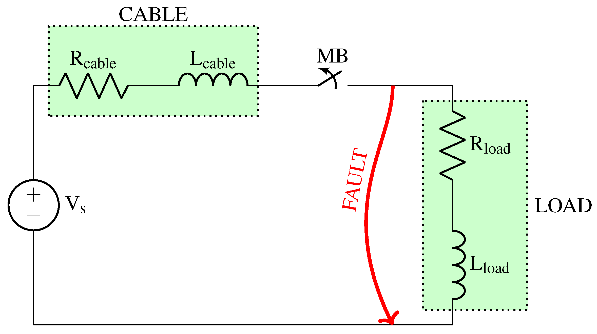
Figure 1 shows the overall system configuration, and
Table 1 lists the corresponding parameters. The fast charger is modeled as an ideal voltage source
, while the cable and load are represented by series combinations of resistors (
,
) and inductors (
,
). The nominal voltage and current are 800
and 800
, respectively, yielding a nominal charging power of 640
. The breaker trips at 1200
, 1.5 times the nominal current, in the event of a fault.
The system is simulated in the Simulink environment. The mechanical circuit breaker is modeled as a programmable voltage source connected in series with an ideal circuit breaker. The programmable voltage source emulates the arc voltage that develops across the contacts during interruption. This voltage is calculated according to the following expression:
where
is the arc voltage,
is the average speed of the contact system,
t is the time since the arc is initiated, and
is a constant relating the arc voltage to its length. According to the experimental results reported in [
20], arc voltages of up to 85
/
can be achieved. However, to ensure a conservative estimation, a value of 50
/
is assumed in this work. With a maximum stroke of 15
, this results in a maximum arc voltage of 1500
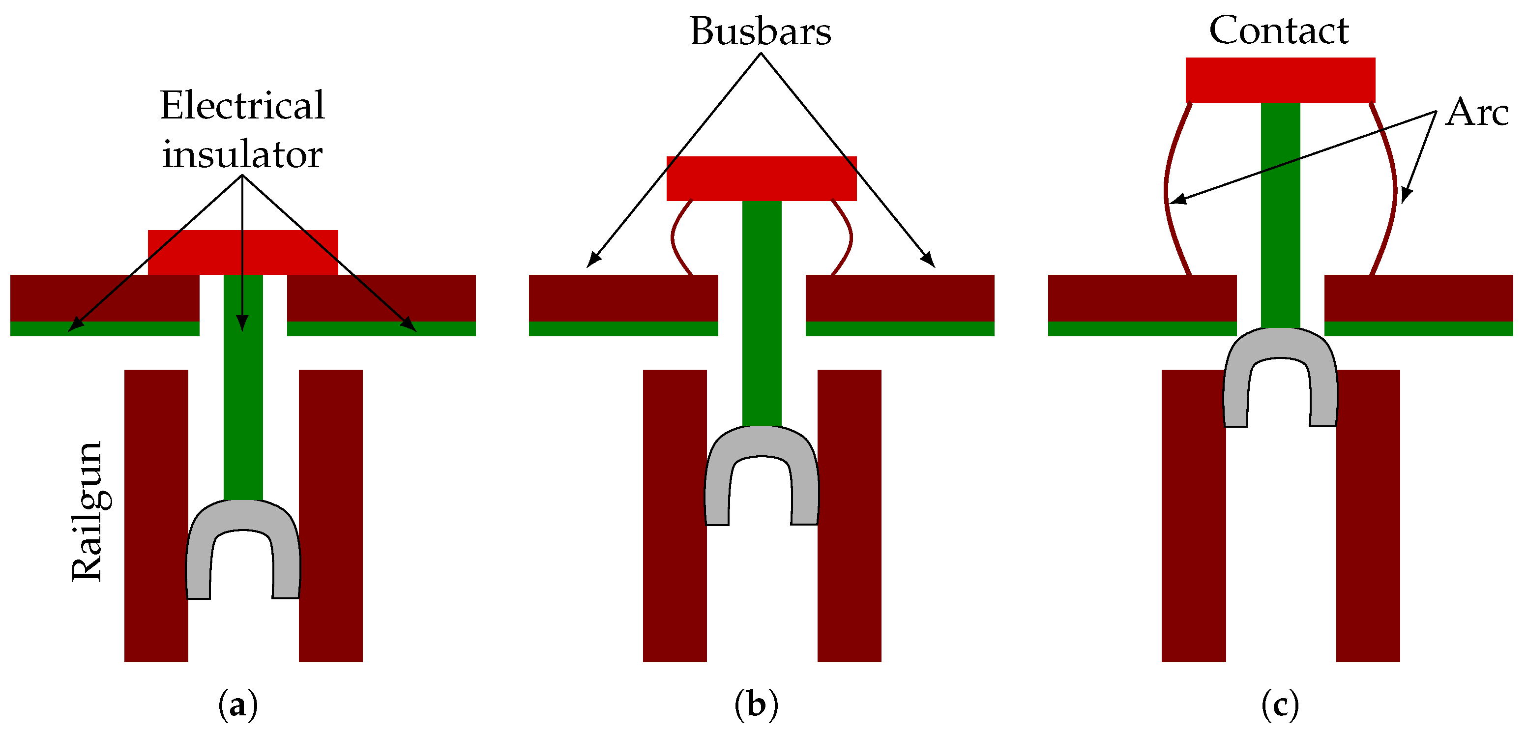
. The factor of 2 accounts for the simultaneous arcing on both sides of the contact, as depicted in
Figure 2. Once the current crosses zero, the ideal circuit breaker opens, completing the current interruption process.
Figure 2 illustrates the operation of the railgun-based mechanical circuit breaker. During normal operation, current flows through the busbars and the closed contact. When a fault occurs, the railgun is fired, the armature starts moving, pushing the contact system and initiating an arc. The armature is mechanically connected to the contact through an electrical insulator, ensuring galvanic isolation between the main current path and the railgun system. As the armature progresses, the contact continues to open until it reaches the end of its stroke. Additional electrical insulators are placed beneath the busbars to prevent an unintended short circuit across the contact gap when the armature reaches its final position.
2.2. Railgun FEM Model
A FEM model has been developed in COMSOL Multiphysics 6.2 to verify the capability of the railgun actuator to achieve the required mechanical performance. Specifically, the model aims to demonstrate that the armature can complete a stroke of 15 within 150 , as required for the successful operation of the circuit breaker.
In electromagnetic modeling, moving domains are typically handled using a moving mesh approach, where dynamic regions slide over stationary ones. However, this method presents significant challenges when solving the magnetic vector potential using curl-conforming elements, as is commonly required in 3D electromagnetic simulations.
The modeling strategy adopted in this work follows the approach described in [
21], which is based on the deformed geometry technique.
In this method, the mesh is continuously deformed to follow the motion of the armature, allowing for accurate representation of the moving domains. To maintain mesh quality and ensure both numerical precision and model convergence, the mesh is periodically remeshed according to the level of deformation. This approach offers a robust framework for simulating systems with significant mechanical displacement while preserving the fidelity of the electromagnetic solution.
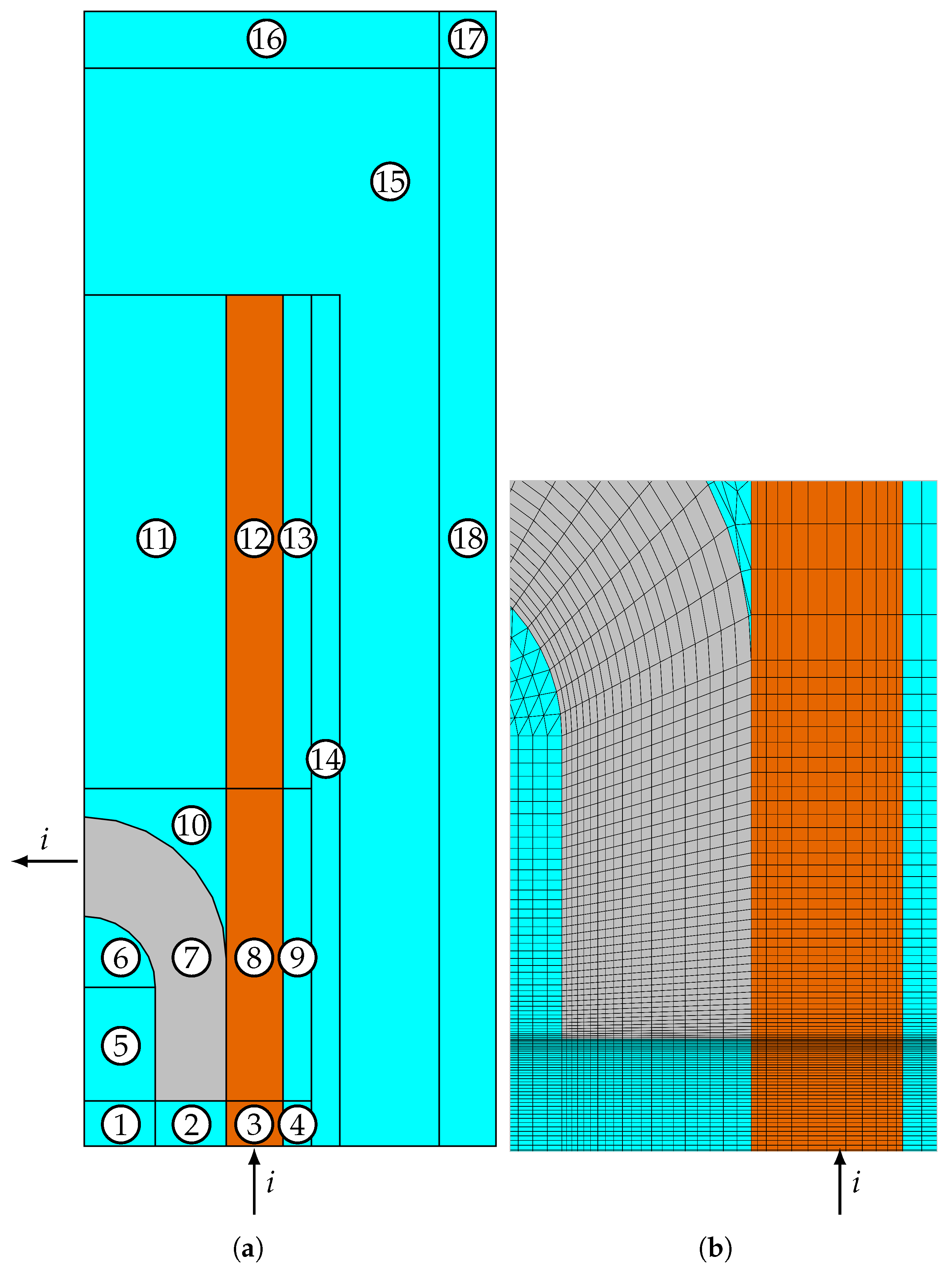
Figure 3 shows the bottom view of the geometry used in the FEM model. Symmetry in the
- and
-planes is exploited to reduce the computational time. The figure also indicates the current input and output of the model
i. Domains 3, 8, and 12 correspond to the rails, while domain 7 represents the armature. The remaining domains represent the surrounding air.
Domains 1–13 represent the deformed geometry. As the armature moves, the mesh elements within these domains will deform or displace accordingly. In contrast, domains 15–18 will remain static and will not undergo any deformation. Domains 1–4 will expand, domains 5–10 will displace, domains 11–13 will contract, and domain 14 will be sticked to the adjacent domains.
It has been verified that, in the deformed geometry domains, the mapped mesh provides greater stability after remeshing compared to a free triangular mesh. In addition, the mesh is refined along the edges and corners to accurately capture the skin effect and the current density concentration in these regions, as illustrated in
Figure 3b.
The rails are modeled using copper, while the armature is made of aluminum to reflect typical material choices in railgun-based actuation systems. The corresponding geometrical parameters of the railgun, including rail and armature dimensions, are summarized in
Table 2.
The problem is formulated under quasi-magnetostatic conditions, with motional effects incorporated into the electric constitutive equation:
where
denotes the current density vector,
denotes the electric field intensity vector,
denotes the electrical conductivity,
denotes the medium’s velocity vector,
denotes the magnetic flux density vector, and
denotes the externally applied current density.
Along the
-symmetry plane, the magnetic field lines are perpendicular to that boundary; therefore, a perfect magnetic conductor boundary condition is applied.
where
denotes the magnetic field strength, and
is the unit normal vector to the boundary surface.
For the remaining outer boundaries, a magnetic insualation boundary condition is applied:
where
is the magnetic vector potential.
To represent the unbounded surrounding air and avoid artificial field reflections, the model is in infinite domains enclosed by infinite domains (see domains 16–18 in
Figure 3. The physical width of the domain is given by the following expression:
where
denotes the actual physical distance, and
denotes the corresponding distance in the model geometry.
The armature is allowed to move along the
y-direction, and its position is determined by solving the second-order kinematic equations derived from Newton’s second law. The driving force
is calculated using Lorentz’s law:
The electromagnetic problem is coupled with an external electric circuit that models the pulse power drive supplying energy to the railgun.
Figure 4 illustrates the equivalent circuit diagram of the electric pulse power drive used in this study:
,
, and
denote the capacitor bank’s capacitance, resistance, and inductance, respectively.
is the inductance of the connection between the capacitor bank and the railgun, while
is the corresponding resistance of that connection.
Table 3 lists the circuit parameters.
3. Results
This section presents the performance of the proposed circuit breaker and compares it with that of existing fast circuit breakers. Subsequently, the results of the FEM model are presented to demonstrate that the breaker can attain an average speed of 100 /.
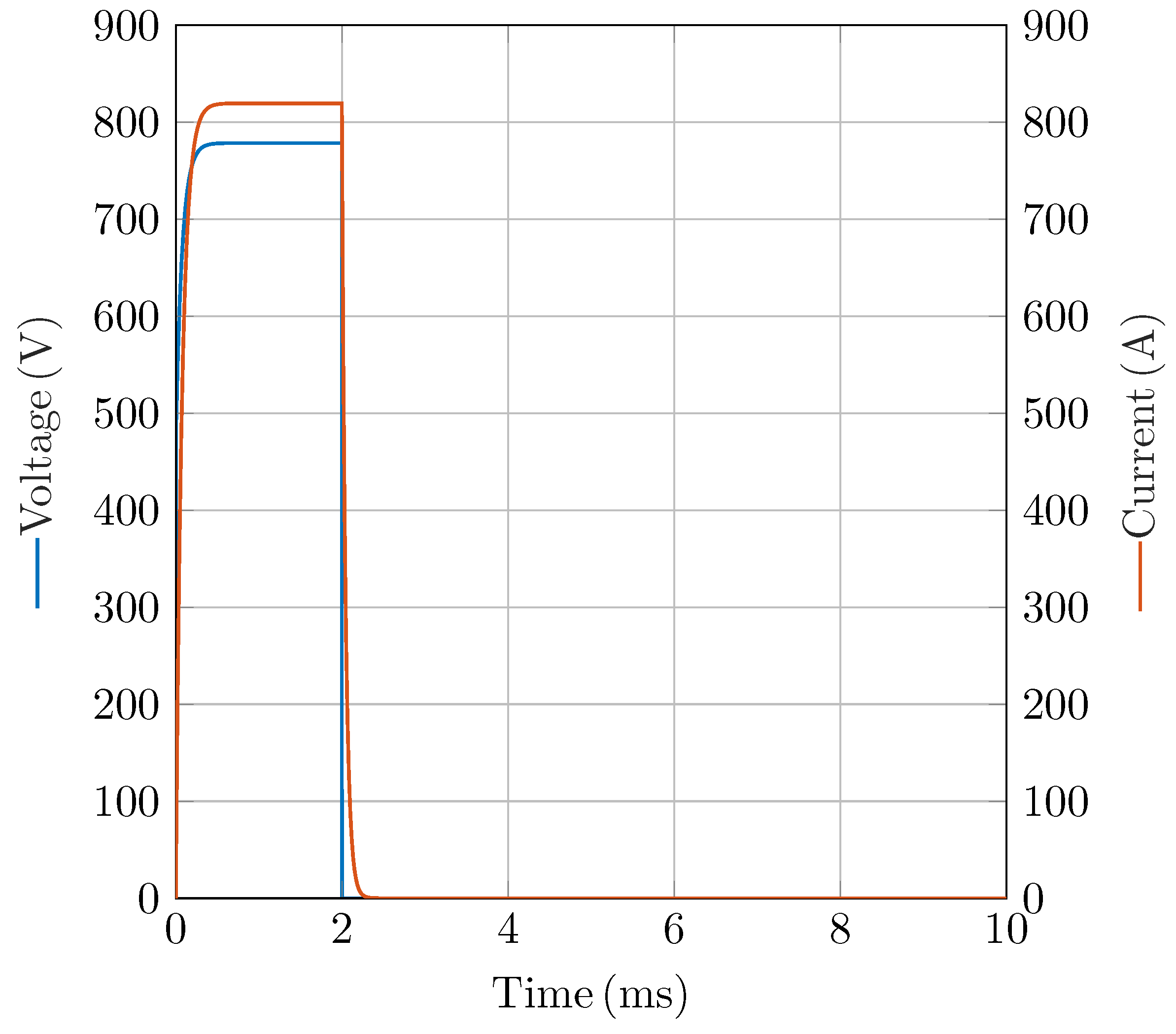
Figure 5 shows the load-side waveforms. The voltage is ramped to 800
and the current to 800
within
. A hard short circuit is imposed at 2
; thereafter, both voltage and current collapse to zero within 250
.
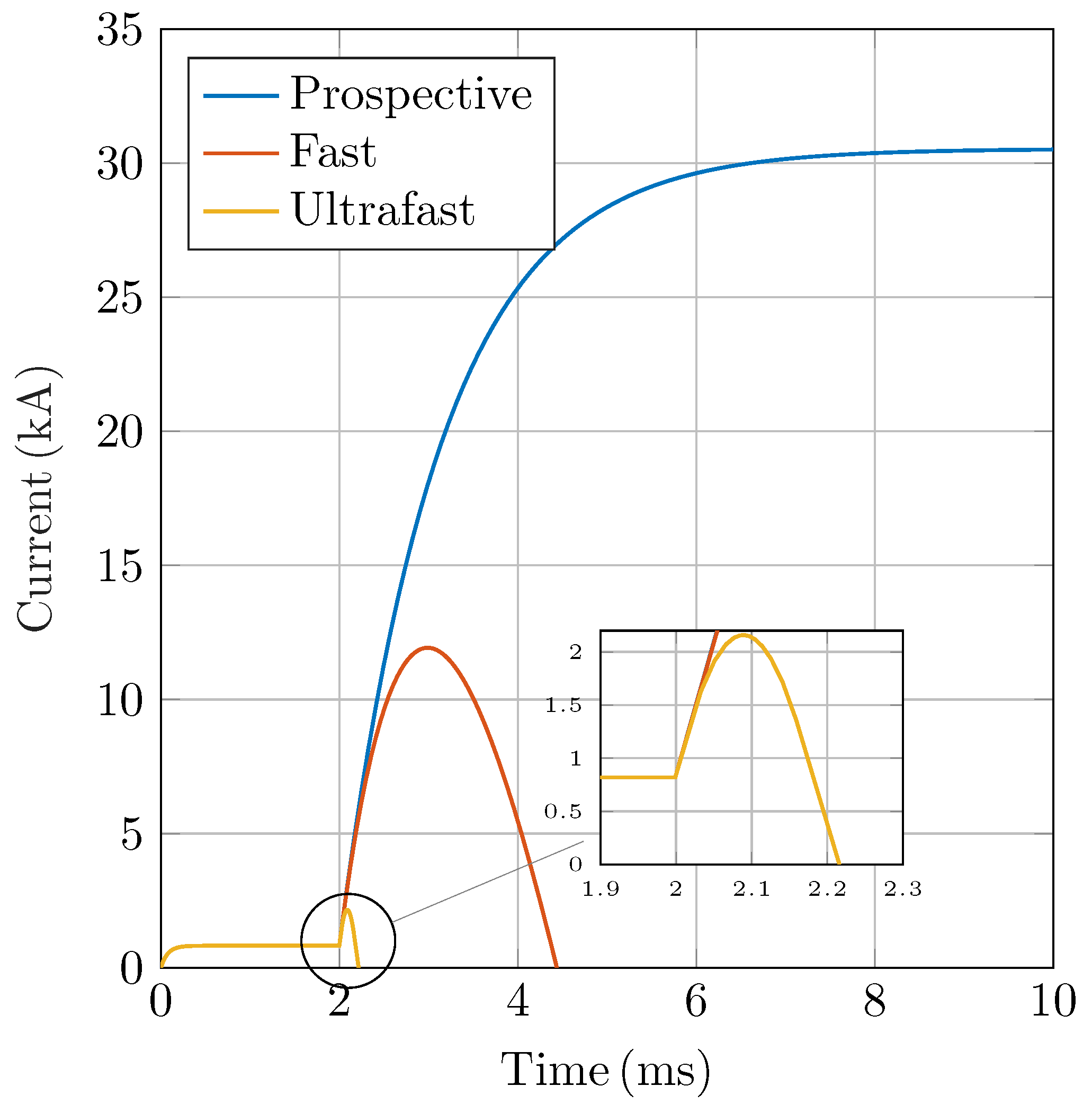
Figure 6 shows that a short circuit in the proposed system can reach a prospective current of 32
. A conventional fast breaker opening at 5
/
limits the peak to 12
and interrupts in
, whereas the proposed 100
/
breaker limits it to 2200
and interrupts in just 200
, demonstrating the benefits of faster contact separation.
Figure 7 shows that, when a conventional fast breaker is used, a peak arc voltage of approximately 1200
develops over an interruption time of
. In contrast, using the proposed breaker with a contact opening average velocity of 100
/
results in a higher peak arc voltage of 1500
, reached within just 150
. This demonstrates how faster contact separation not only shortens the interruption time but also increases the arc voltage, aiding in quicker current extinction.
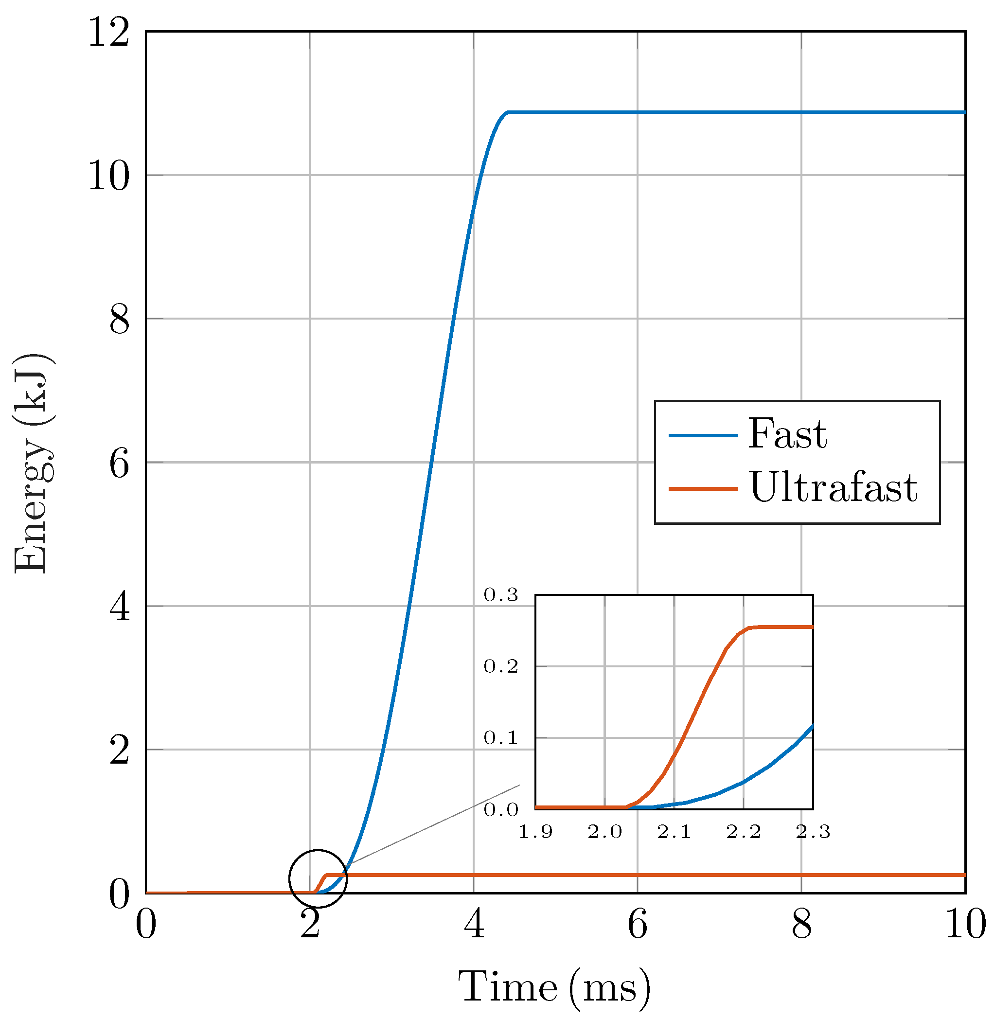
The proposed concept not only interrupts fault currents rapidly but also effectively limits them. By acting as a fault current limiter, it interrupts the current before it reaches damaging levels. A useful analogy is that of a snowball: stopping it at the top of the hill is far easier than after it has gained mass and speed rolling downhill. Similarly, the earlier the interruption, the less energy must be dissipated in the circuit breaker. It can be observed in
Figure 8 that the ultrafast breaker absorbs only 250
, compared to 11
in the case of a fast breaker. As a result, the mechanical and thermal stress on the ultrafast breaker is significantly reduced. This not only minimizes damage to the contacts but also enhances the overall durability, reliability, and operational lifetime of the device.
The results presented in this section are based on the assumption that the actuator can achieve an average velocity of 100 /, corresponding to a total displacement of 15 within 150 . To validate this assumption, the results of the railgun FEM model are presented.
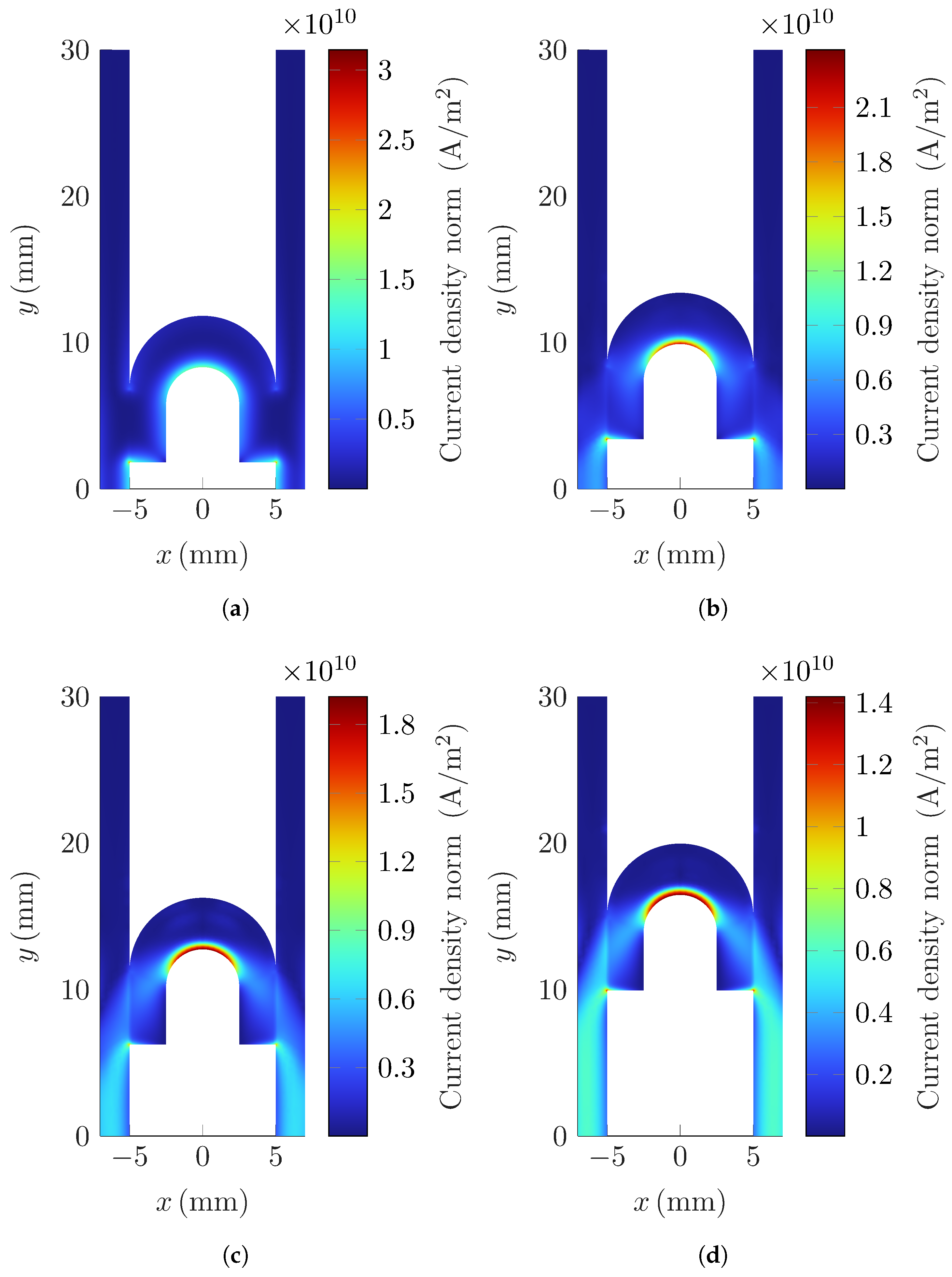
Figure 9 illustrates the current distribution at various time instants. Initially, as shown in
Figure 9a, the velocity of the armature is low, but the system experiences a high rate of current rise (
). Under these conditions, the skin effect dominates, causing the current to concentrate along the inner edges of both the rails and the armature. As time progresses, the
decreases, leading to a more uniform current distribution in the rails, as observed in
Figure 9d. However, the current distribution within the armature remains highly influenced by the velocity skin effect. Due to the high speed of the armature at later stages, the induced electromagnetic fields continue to push the current towards the rear surface, resulting in a non-uniform and velocity-dependent distribution. This behavior highlights the critical role of both transient and motional effects in determining the current path within the system.
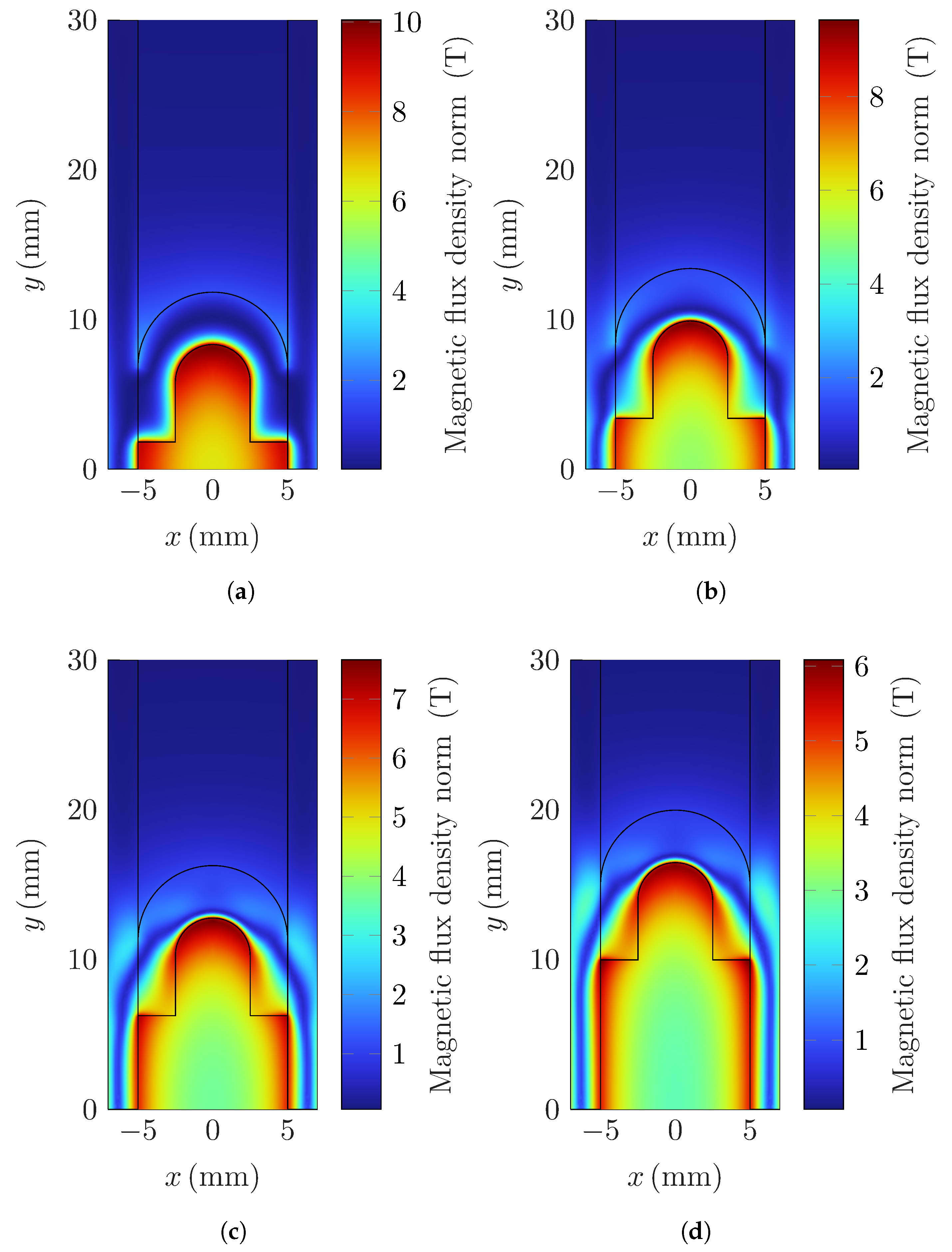
Figure 10 shows the spatial distribution of the magnetic flux density within the railgun system. Magnetic field intensities as high as 10
are reached during peak operation, indicating the presence of strong electromagnetic interactions. It is particularly noteworthy that the magnetic flux density exhibits significant concentration along the inner edges of the rails and the rear section of the armature. This phenomenon is largely attributed to the combined effects of the skin effect and the geometry of the current path, which channel the current—and thus the associated magnetic field—toward these regions.
The resulting electromagnetic interaction between the magnetic field and the current density, described by the Lorentz force law, gives rise to two critical forces: a driving force that accelerates the armature forward and a lateral repulsive force that acts on the rails. While the former is essential for the rapid contact separation in the railgun-based breaker, the latter imposes mechanical stress on the rail structure and must be considered in the mechanical design.
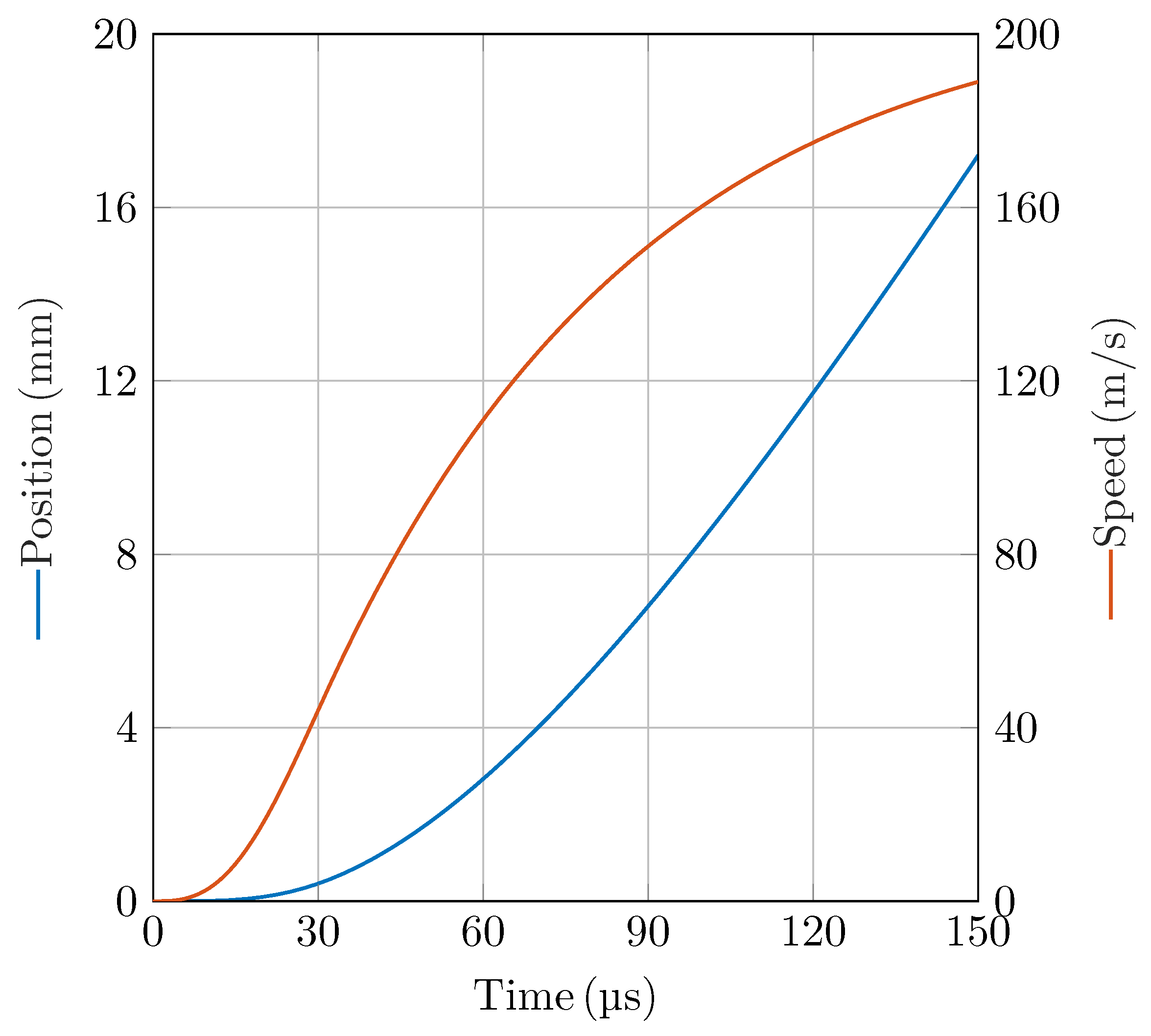
Figure 11 illustrates the simulated position and speed profiles of the armature over time. The results reveal that the armature rapidly accelerates, reaching a terminal speed of approximately 190
/
and achieving a maximum displacement of 17
. This figure is of critical importance, as they validate the assumptions made in the system-level simulation, where an average speed of 100
/
and a total displacement of 15
within 150
were used as boundary conditions for the operation of the proposed circuit breaker. The close agreement between the FEM model and the system-level parameters supports the physical feasibility of the railgun-based actuator concept. Furthermore, the rapid acceleration and significant displacement of the armature within such a short time window demonstrate that the electromagnetic forces generated are sufficient to drive the contact system with the required performance. This confirms that the railgun actuator is capable not only of achieving the mechanical response needed for ultrafast interruption, but it is also capable of doing so within the spatial and temporal constraints necessary for effective fault current limitation.
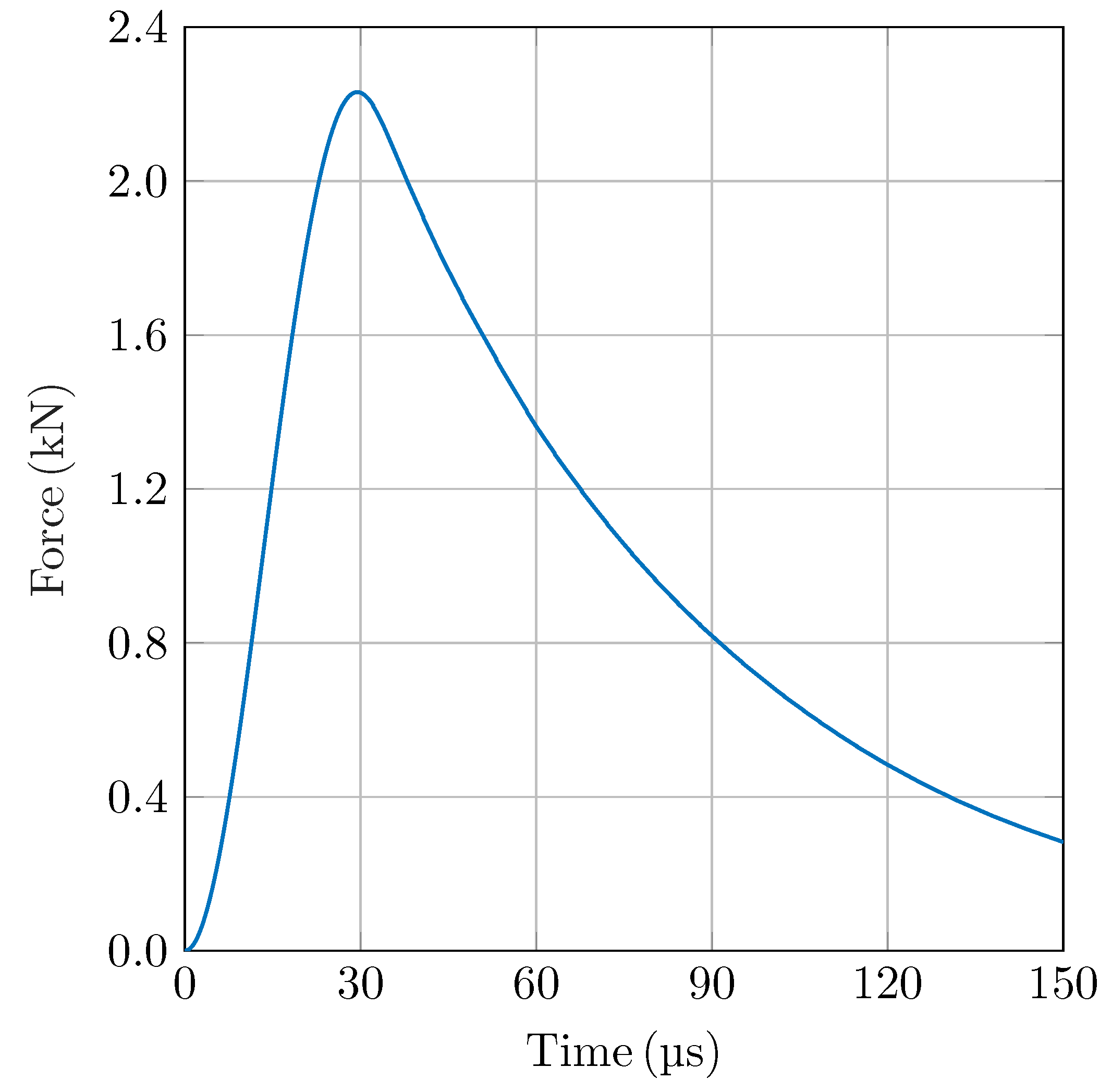
Figure 12 shows the time evolution of the electromagnetic force acting on the armature during the acceleration phase. The results indicate a sharp rise in force shortly after current injection, with a peak value of approximately
reached within the first 30
. This high initial force is critical for rapidly accelerating the armature and achieving the required displacement within the desired time frame. The steep force rise is a direct consequence of the strong interaction between the high current density and the magnetic field concentrated near the rail and armature edges, as discussed previously.
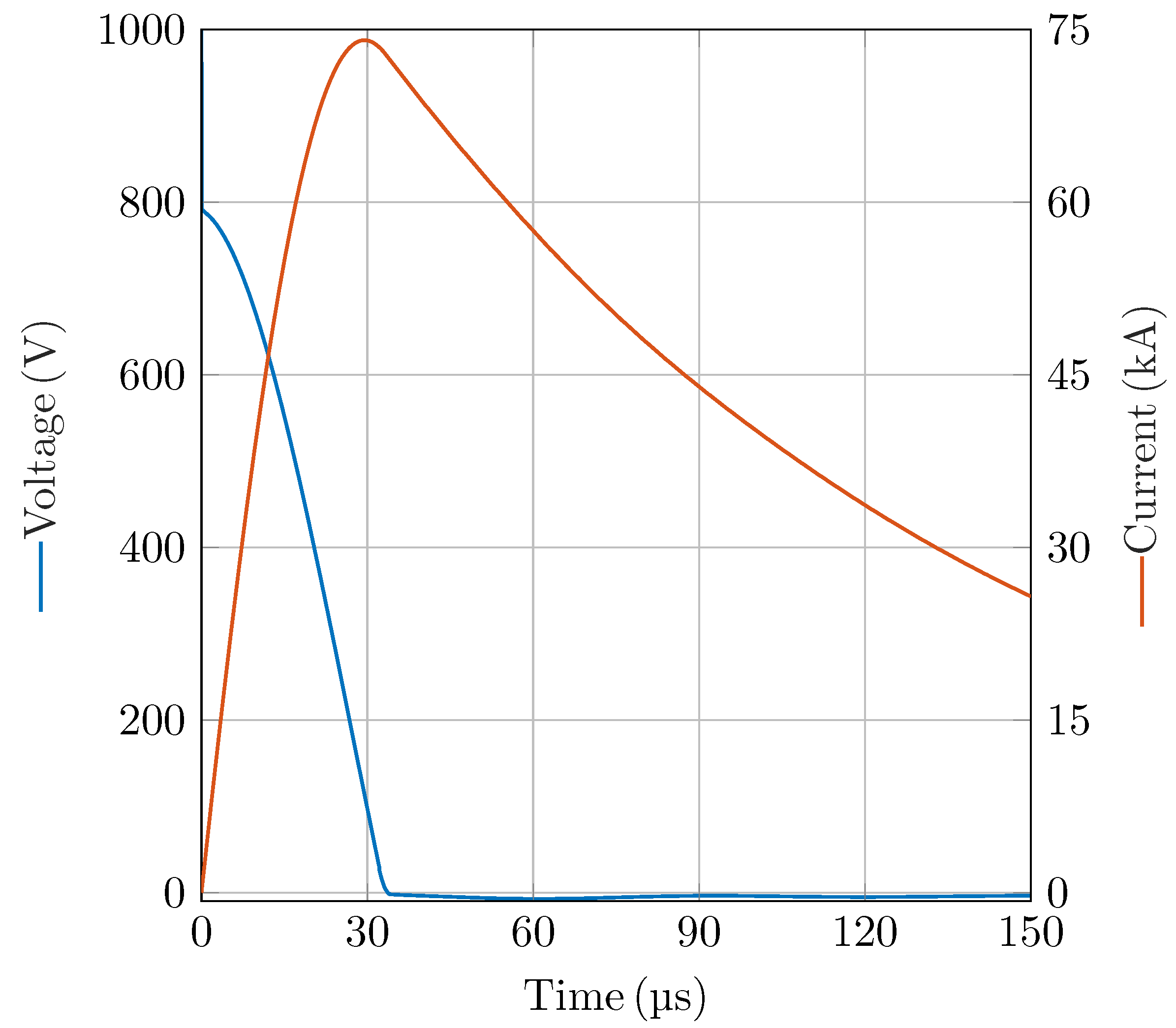
Figure 13 presents the capacitor bank voltage current during the railgun operation. It can be observed that the current rapidly rises to a peak value of approximately 75
within just 30
. Additionally, the initial voltage drop across the capacitor bank is not solely due to charge depletion, but is significantly influenced by the high rate of change of current (
di/
dt) and the parasitic inductance of the capacitor bank
:
where
and
denote the voltage and current of the capacitor bank, respectively, and
represents its initial voltage.
The current profile plays a critical role in the design of the power stage, as it directly influences the selection and dimensioning of the switching devices, such as thyristors and diodes.
4. Discussion
The results presented in this work demonstrate the feasibility and benefits of employing a railgun-based actuator for ultrafast mechanical DC circuit breakers in high-power applications such as fast-charging stations. Compared to fast mechanical circuit breakers with opening speeds around 5 /, the proposed solution provides significant improvements in both current limiting and interruption speed.
The system-level simulation shows that the proposed breaker limits the fault current to 2200 and interrupts it within 200 , in contrast to a fast mechanical breaker which allows peak currents of up to 12 and takes to interrupt. This fast interruption greatly reduces the energy dissipated during fault events— 250 compared to 11,000 J—leading to lower thermal stress and mechanical wear. As a result, the durability and reliability of the breaker are substantially improved.
The railgun actuator is key to achieving this performance. Finite element simulations confirm that the actuator accelerates the armature to speeds exceeding 190 /, reaching a displacement of 15 in under 150 . Electromagnetic analysis shows that this rapid actuation produces a peak force of and magnetic field densities up to 10 , validating the concept’s effectiveness under extreme conditions.
The skin effect and velocity skin effect also play a significant role in current distribution. At early time instants, when the armature velocity is low but the system exhibits high , current concentrates along the inner edges of the rails and armature. As time progresses and decreases, the current in the rails distributes more uniformly, while the current in the armature remains influenced by high velocity, confirming the dominance of the velocity skin effect.
To further validate the long-term reliability of the proposed actuator, future work will include endurance experimental tests aimed at assessing the thermal and mechanical effects of repeated fault interruptions on both the railgun actuator and the breaker components. These tests will provide essential insights into wear mechanisms, material fatigue, and overall durability under realistic operating conditions.
Moreover, the optimization of the railgun topology represents a promising research direction. In particular, configurations such as multiturn and multipole railguns will be investigated, as they are expected to deliver higher performance while reducing the required size of the capacitor bank. Such topologies may enable more compact and energy-efficient designs, further enhancing the practical feasibility of railgun-based ultrafast DC circuit breakers.
In addition, it is worth comparing the proposed concept with solid-state circuit breakers, since the achieved interruption speed is close to that of semiconductor-based solutions. While a solid-state breaker could, in principle, be employed for this application, several limitations must be considered. First, solid-state devices do not provide galvanic isolation and tend to fail in a short circuit state, which could compromise the interruption capability under certain fault scenarios. Second, their on-state resistance is typically in the range of 1 –5 , significantly higher than the 50 –100 characteristic of mechanical breakers. As a result, solid-state breakers require dedicated cooling systems to handle conduction losses, which increases system cost and volume. By contrast, the proposed railgun-based breaker is more cost-effective, with the main cost drivers being the capacitor bank and the thyristor. The capacitor bank, however, is conservatively oversized in the present design and can be reduced by a factor of four, while the thyristor could be substituted by a simpler and cheaper triggered spark gap.
It is also important to mention, that the formation of post-arc current, caused by residual plasma conduction after arc extinction, has not been directly measured in this study. However, given the very short contact opening time and the strong elongation of the arc in the railgun geometry, the post-arc conduction interval is expected to be negligible compared to the overall interruption time. Future work will include experimental studies to quantify post-arc current and its potential impact on contact erosion and dielectric recovery.
5. Conclusions
This work presents a novel concept for ultrafast DC circuit interruption using a railgun-based mechanical actuator. The proposed system achieves fault current interruption in less than 200 and limits the peak current to only 2200 , compared to 12 in conventional fast mechanical breakers. By interrupting the current at such an early stage, the energy dissipated in the breaker is drastically reduced, leading to less thermal stress, reduced contact erosion, and increased reliability and lifespan.
The railgun actuator enables contact opening speeds exceeding 190 /, which are significantly higher than those of state-of-the-art mechanical actuators. Finite element simulations confirm the feasibility of reaching a displacement of 15 in under 150 , validating the key assumption behind the system-level model.
Additionally, the electromagnetic analysis highlights critical physical phenomena, such as the skin effect and the velocity skin effect, which influence current distribution in the rails and armature during switching transients. The ability to model and control these effects is essential for ensuring effective and reliable operation.
Overall, the results demonstrate that ultrafast mechanical circuit breakers based on railgun actuators are a promising technology for future high-power DC applications, offering enhanced performance in terms of speed, current limiting capability, and energy dissipation.
