Article

Assessment of Ejector-Expansion Heat Pump Systems with Low GWP Refrigerants for Electric Vehicles

College of Architecture and Civil Engineering, North China University of Science and Technology, Tangshan 063210, China
*
Authors to whom correspondence should be addressed.
World Electr. Veh. J. 2025, 16(9), 505; https://doi.org/10.3390/wevj16090505
Submission received: 27 June 2025 / Revised: 19 August 2025 / Accepted: 3 September 2025 / Published: 8 September 2025

Abstract

This study addresses the critical challenge of developing efficient thermal management systems for electric vehicles by proposing and evaluating two novel ejector-expansion heat pump configurations: single-evaporator (SEEHP) and dual-evaporator (DEEHP) systems. Through comprehensive thermodynamic analysis across six representative Chinese cities using four refrigerants (R134a, R32, R152a, R290), system performance via coefficient of performance (COP) and lifecycle CO2 emissions were assessed. The results demonstrate significant advantages over conventional (CBHP) and vapor injection (VIHP) systems, particularly in extreme cold conditions. The SEEHP configuration achieves 10–30% COP improvements versus CBHP, while DEEHP shows 7–15% enhancement. The corresponding lifecycle emission reductions reach 9–14% for SEEHP and 2–11% for DEEHP relative to conventional systems. Among the refrigerants, R290 systems achieve the lowest equivalent CO2 emissions due to superior COP in Beijing, Shanghai, Chongqing, Kunming and Guangzhou, whereas R32 systems yield minimal emissions owing to its exceptional heating capacity in Harbin. These findings highlight ejector technology’s potential for substantially improving electric vehicle energy efficiency while reducing environmental impact.

1. Introduction

Electric vehicles (EVs), recognized as a promising alternative to address fossil energy scarcity and environmental concerns, have garnered significant research interest in recent years [1]. Transitioning from internal combustion engine vehicles to EVs represents a critical pathway toward achieving carbon neutrality in the transportation sector through zero-emission mobility. The cabin cooling and heating system is essential to meet the requirements of the thermal environments inside the vehicle and to ensure safe visibility. Among the auxiliary components of EVs, the heat pump system exhibits the highest energy consumption [2]. In general, cabin cooling and heating systems can reduce the driving mileage of EVs by an average of 30–40% according to the size of the system and driving cycle [3,4].
The heat pump system is more energy-saving than the traditional single refrigeration system with individual heaters [5,6] and is considered a practical and promising solution for the cabin cooling and heating systems in EVs [7,8]. However, most of the heat pumps being studied in EVs are used R410A or R134a as refrigerants, which belong to high global warming potential (GWP) refrigerants and will be phased out under the Kigali Amendment to the Montreal Protocol [9,10]. Currently, the potential low-GWP refrigerants for EVs principally include R32, R290, R152a, R1234yf and R744, among others. Direk et al. [11] found that R134a could be directly replaced by R152a in a system without any operation troubles. Yu et al. [12] demonstrated that R32 refrigerant outperforms R410A in both capacity and coefficient of performance (COP). Yu et al. [13] experimentally evaluated three R32-based mixture refrigerants in the EV heat pump systems and reported that the system using the mixtures performs similarly to the R410A system in both heating and cooling mode. Ning et al. [14] developed a multifunctional dual-stage compression heat pump for EVs, revealing marginally superior COP with R290 compared to R410A and R32. Song et al. [15] found that the R744 heat pump possesses satisfactory heating performance for an electric bus with a COP of 1.78 at an ambient temperature of −20 °C. Dong et al. [16] experimentally found that the heating capacity of the R744 system was sufficient to satisfy the heating demand of EVs in winter without additional electric heating elements. Under −20 °C ambient conditions, the R744 system achieved a maximum COP of 2.16. Wang et al. [17] indicated that there was a pseudo-optimal heat rejection pressure at both subcritical and transcritical conditions under constant heating capacity operation conditions for the R744 heat pumps of EVs. Experimental data from Huang et al. [18] indicated approximately 5.8% higher cooling capacity in R290 heat pumps versus R744 systems for EVs. In 2024, Khalid et al. [19] validated R456A as a non-flammable R134a alternative with about 5% COP reduction in heating mode, while Kwon et al. [20] revealed that indirect R290 systems achieve 4.9% higher heating COP than direct R1234yf configurations at −20 °C despite flammability constraints. In 2025, Zhao et al. [21] developed an R290-based thermal management system achieving COP > 1 at −20 °C with 6.43% COP improvement through waste heat recovery.
Heat pump efficiency markedly decreases under low ambient temperatures, contradicting EV thermal demands. Consequently, enhancing energy efficiency remains a key research focus. Vapor injection heat pump (VIHP) technology is widely adopted for performance augmentation [22,23]. Lai et al. [24] proposed a VIHP using a flash tank, and 5~15% performance improvement was reported. Luo et al. [25] reported a 20% heating COP improvement via precise injection pressure regulation, while Li et al. [26] established the superior efficacy of downstream versus upstream vapor injection configurations in R134a EV heat pumps. Experimental studies by Xu et al. [27] demonstrated 5.7% and 4.7% enhancements in heating capacity and COP, respectively, when implementing VIHP technology in EVs, with effective operation maintained above −15 °C ambient temperatures. Comparative analyses reveal significant performance advantages over conventional systems: Li et al. [28] identified superior heating capacity in R1234yf VIHP configurations relative to R134a CBHP systems, while Peng et al. [29] numerically verified simultaneous improvements in both COP and heating capacity for R744-based VIHP systems. Lee et al. [30] developed a multi-stage waste heat recovery VIHP configuration capable of 72.5% heating capacity augmentation under extreme −20 °C conditions.
Ejector-based expansion devices, which recover expansion work, constitute another effective performance enhancement approach [31,32]. In the subcritical and transcritical systems, the COP improvement due to ejector-expansion is usually in the range of 5–20% and 7–40%, respectively [33]. Peris Pérez et al. [34] reported elevated annual average COP with reduced costs in R744 cycles. Ameur and Aidoun [35] observed 14% heating capacity and 9% COP improvements over conventional basic heat pump (CBHP) systems. Elbarghthi et al. [36] noted 2% higher cooling COP versus parallel compression systems. Gao et al. [37] developed an R290-based dual-evaporator configuration, yielding 43% COP enhancement relative to CBHP systems. Cao et al. [38] quantified 12% and 22% COP improvements in dual-evaporator configuration versus single-evaporator and CBHP configurations, respectively. Qin et al. [39] engineered a transcritical R744 ejector heat pump for concurrent heating/cooling applications, demonstrating 12% exergy efficiency gains over traditional ejector systems with a one-year payback period. However, there is much less literature on the applicability of ejector-expansion heat pumps in the cabin cooling and heating system of EVs. In 2007, Oshitani et al. [40] pioneered a dual-evaporator concept for automotive cabin thermal management. It was found that this system has better operational stability and adaptability to low-pressure refrigerants than the single-temperature evaporation ejector-expansion system. This technique was also used in the cabin cooling and heating system of Toyota Prius to enhance the system performance [41,42]. The two evaporators and the ejector were integrated together to decrease the device volume. The compressor energy consumption was decreased by 11% and 18% at the ambient temperatures of 25 °C and 35 °C, respectively, owing to the ejector utilization. In 2014, Boumaraf et al. [43] made a theoretical analysis of DEEHP system using R134a/R1234yf and found that the COP increase in DEEHP system can reach 17% when the condensation temperature is lower than 40 °C. In 2015, Unal et al. [44] analyzed DEEHP system theoretically using the equal area mixing ejector model and 15% COP superiority over conventional systems was found. In 2017, Ünal et al. [45] achieved 55% evaporator size reduction for DEEHP system, lowering initial investment and total weight. In 2022, Zou et al. [46] developed a parallel dual-ejector transcritical R744 configuration for EVs with 17–23% (cooling) and 18–20% (heating) COP enhancements over CBHP system. In 2024, Yang et al. [47] conducted experimental characterization of a CO2 ejector-expansion heat pump for EVs across typical cooling/heating modes (−30 °C to 50 °C). The system achieved maximum a COP enhancement of 31.0% (vs. VIHP) at the 45 °C design point. However, heating capability substantially diminished under subzero conditions due to thermal operating point mismatch. In 2025, Ren et al. [48] quantified 15.2% COP improvement and 5.3% range extension at 45 °C using ejectors.
Our research team has methodically advanced ejector-expansion technology through a structured program spanning fundamental thermodynamics to applied system optimization. In 2015, Zhang et al. [49] quantified R32 ejector-expansion cycle enhancements, demonstrating 8.84–15.84% exergy destruction reduction and 5.22–13.77% COP improvement through optimizing suction nozzle pressure drop. In 2018, Zhang et al. [2] reviewed EV air conditioning-specific challenges, identifying 30–40% range reduction from HVAC loads and positioning ejector-expansion heat pumps as a promising solution. In 2020, Zhang et al. [33] cataloged global ejector advancements, establishing design principles for ejector-expansion systems and advanced configurations. Most recently, Wang et al. [50] employed 3D CFD parameterization to achieve 23.6% entrainment ratio enhancement in R410A ejectors through geometric sensitivity analysis.
Owing to the above, ejector-expansion technology significantly enhances EV heat pump performance. But most of the previous studies only focused on the performance of a single mode (heating or cooling). Little attention has been focused on its annual thermodynamic performance and lifetime equivalent CO2 emissions considering the influences of climate conditions in China. Thus, two ejector-expansion heat pump configurations for cabin cooling and heating of EVs, namely SEEHP and DEEHP, are proposed in this paper. This study establishes thermodynamic models for ejector-expansion heat pumps, evaluating COP and lifetime CO2 emissions against CBHP and VIHP benchmarks. Using the Total Equivalent Warming Impact (TEWI) methodology, this study assesses four refrigerants (R134a, R32, R152a, R290) across six Chinese climatic regions to identify optimal working fluids and system configurations. The work aims to provide theoretical foundations for enhancing EV heat pump efficiency and guide practical implementations throughout China’s diverse climate zones.

2. System Description

2.1. Conventional Basic Heat Pump System (CBHP)

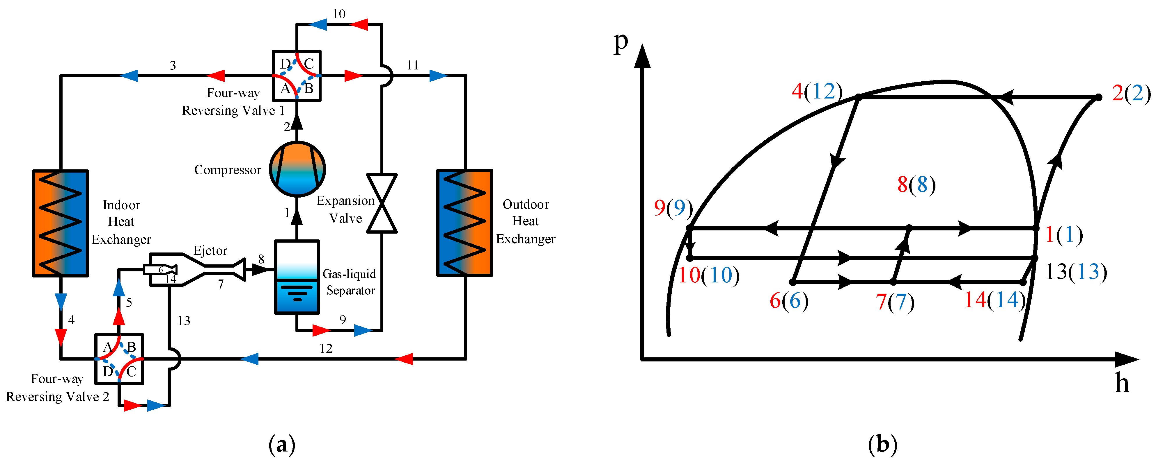
As illustrated in Figure 1, the CBHP system comprises a compressor, indoor/outdoor heat exchangers (IHE/OHE), a four-way reversing valve (FwRV), an expansion valve (ExV) and a gas–liquid separator (GLS). During cooling operation, FwRVs are configured with passages B and D open while passages A and C remain closed. During heating operation, FwRVs are configured with passages A and C open while passages B and D remain closed.

2.2. Vapor Injection Heat Pump System (VIHP)

Figure 2 illustrates the VIHP system configuration, comprising a quasi-two-stage compressor, an IHE, an OHE, two FwRVs, a flash tank (FLT) and two ExVs. During cooling operation. FwRVs are configured with passages B and D open while passages A and C remain closed. The working fluid exiting the compressor enters the OHE through passage B of the FwRV1 and releases heat to the external environment of the vehicle (2-3-4). Afterward, the working fluid enters the FLT through the FwRV2 and the auxiliary throttle valve (4-18-19-7-8-9). The vapor from the FLT is injected into the compressor intermediate admission port. The liquid at the bottom of the FLT flows into IHE through the FwRV2 and ExV2 for cabin cooling (10-12-13-14-15-16). The working fluid is returned to the compressor through passage D of the FwRV1 (16-17-1). Thus, the refrigeration cycle is realized. During heating operation, FwRVs are configured with passages A and C open while passages B and D remain closed. The working fluid exiting the compressor enters the IHE through passage A of the FwRV1 for cabin heating (2-16-15). Afterward, the working fluid enters the FLT through the FwRV2 and the auxiliary throttle valve (15-20-21-12-8-9). The saturated vapor phase from the FLT upper section is introduced into the compressor’s intermediate admission port. The liquid at the bottom of FLT flows into OHE through the FwRV2 and ExV1 to absorb heat from the vehicle’s external environment (10-7-6-5-4-3), then returns to the compressor through the passage C of the FwRV1 (3-17-1). Thus, the heating cycle is realized.

2.3. Single-Evaporator Ejector-Expansion Heat Pump System (SEEHP)

Figure 3 illustrates the SEEHP system configuration, comprising a compressor, an IHE, an OHE, dual FwRVs, an ExV and a GLS. During cooling operation, FwRVs are configured with passages B and D open while passages A and C remain closed. GLS vapor is drawn into the compressor where it undergoes compression to the high-pressure state (1-2) and then enters the OHE through passage B of the FwRV1 for releasing heat to the vehicle’s external environment (2-11-12). Afterward, the working fluid flows through FwRV2 passage B into the ejector’s primary nozzle (12-5-6). The liquid exiting the GLS undergoes throttling in the ExV before progressing to the IHE via FwRV1 passage D (9-10-3-4), where it provides cabin cooling. Subsequently, the working fluid exiting the IHE is entrained by the high-speed two-phase fluid from the primary nozzle through passage D of the FwRV2 (4-13). The two streams combine in the mixing channel before undergoing diffuser-induced deceleration and compression (7-8), with the resulting two-phase mixture discharging into the GLS. Thus, the refrigeration cycle is realized. During heating operation, FwRVs are configured with passages A and C open while passages B and D remain closed. The IHE facilitates cabin heating while the OHE absorbs heat from the vehicle’s external environment.

2.4. Dual-Evaporator Ejector-Expansion Heat Pump System (DEEHP)

Figure 4 illustrates the DEEHP system configuration, comprising a compressor, an IHE, an OHE, a high-temperature evaporator (HTE), two FwRVs, three TwVs and an ExV. During cooling operation, FwRVs are configured with passages B and D open while passages A and C remain closed. Passages A and B of TwV1 and TwV2 are opened, and passages C of TwV1 and TwV2 are closed. TwV3 is fully opened. The working fluid exiting the compressor enters the OHE through passage B of FwRV1 to release heat to the external environment of the vehicle (2-12-11). The working fluid enters TwV3 and then splits into two streams: one stream traverses passage C of TwV3 and then enters the ejector’s primary nozzle through passage B of FwRV2 (11-10-6). The other stream traverses TwV3 passage B, undergoes ExV throttling (11-15-14), then passes through TwV1 passage B, TwV1 passage A and FwRV1 passage D (13-3-4) before entering the IHE for cabin cooling. Then, the working fluid exiting the IHE is entrained by the high-speed two-phase fluid from the primary nozzle after consecutively through passage A of the TwV1, passage C of the TwV2 and passage D of the FwRV2 (4-5-7). The two streams undergo mixing in the chamber followed by deceleration and compression in the diffuser (8-9), with the resulting two-phase flow directed to the HTE for cabin cooling (9-1). Thus, the refrigeration cycle is realized.
During heating operation, FwRVs are configured with passages A and C open while passages B and D remain closed. Passages A and C between TwV1 and TwV3 are opened, and passages B of TwV1 and TwV3 are closed. TwV2 is fully opened. The working fluid exiting the compressor enters the IHE through passage A of FwRV1 to heat the passenger cabin (2-3-4). The working fluid enters TwV2 and is then divided into two streams: one stream traverses passage B of the TwV2 and then enters the ejector’s primary nozzle through passage A of the FwRV2 (4-5-6). The other stream passes through passage C of TwV2 and then is throttled by the ExV (17-16) and then enters the OHE to extract external environmental heat after consecutively going through the passage C of TwV1, passage A of TwV1 and passage C of FwRV1 (16-13-12-11). Then, the working fluid exiting the OHE is entrained by the high-speed two-phase fluid from the primary nozzle after consecutively through passage A of the TwV3, passage C of TwV3 and passage C of FwRV2 (11-10-7). The two streams undergo mixing in the chamber followed by deceleration and compression in the diffuser (8-9), with the resulting two-phase flow directed to the HTE for cabin cooling (9-1). Thus, the heating cycle is realized.

3. Assessment Methodology

3.1. The Investigated Refrigerants

Table 1 lists key properties of four refrigerants for EV heat pumps. The GWP values and the safety data of the refrigerants are gained based on the Intergovernmental Panel on Climate Change (IPCC) and the standard ISO 187 [51], respectively. All the four refrigerants have zero ozone depletion potential (ODP). R134a has the highest GWP value and will be eliminated in the future. The GWP values of R152a and R290 are very low. In terms of safety, these four refrigerants are categorized as “A”, which indicates that if the working fluid is released, it will not cause acute toxic harm to the human body. R134a is nonflammable. R32 and R152a are categorized as “A2L” and “A2” refrigerants, respectively, signifying mild flammability. Meanwhile, R290 is categorized as an “A3” refrigerant, meaning it is highly flammable. R1234yf is not considered here due to its high cost and the production of trifluoroacetic acid (TFA) during degradation.

3.2. Thermodynamic Model

The thermodynamic performances of the four systems are investigated based on the following assumptions:
(1)
The flow is one-dimensional and steady.
(2)
Heat exchanger and piping operate without appreciable pressure losses.
(3)
Fixed 20 kPa evaporator-mixing chamber pressure difference [52,53].
(4)
All compression and expansion processes occur under adiabatic conditions.
For the investigated refrigerants, the compressor isentropic efficiency is as follows [54]:
η com , s = 0.874 0.0135 p com , out p com , in ,
  • where p com , in and p com , out are the compressor inlet and outlet pressure, respectively.
  • For CBHP system,
COP values for both heating and cooling modes of CBHP are as follows:
C O P CBHP , Heating = h IHE , in h IHE , out h com , out h com , in ,
C O P CBHP , Cooling = h IHE , out h IHE , in h com , out h com , in ,
where h com , out is determined as follows:
h com , out = h com , in + h com , out , s h com , in η com , s .
For VIHP system,
COP values for both heating and cooling modes of VIHP are as follows:
C O P VIHP , Heating = h IHE , in h IHE , out 1 x ft , Heating h com , im , out h com , in + h com , out h com , im , out ,
C O P VIHP , Cooling = 1 x ft h IHE , out h IHE , in 1 x ft , Cooling h com , im , out h com , in + h com , out h com , im , out ,
where h com , im , out and h com , out are determined as follows:
h com , im , out = h com , in + h com , im , out , s h com , in η com , s ,
h com , out = h com , im , out + h com , out , s h com , im , out η com , s
For the two ejector-expansion heat pump systems,
The entrainment ratio of the ejector, μ, is the ratio between the suction flow mass flow rate, msuc, and the motive flow mass flow rate, mmot. It is as follows [33]:
μ = m suc m mot .
COP values for both heating and cooling modes of SEEHP are as follows:
C O P SEES , Heating = h IHE , in h IHE , out h com , out h com , in ,
C O P SEEHP , Cooling = μ SEEHP h IHE , out h IHE , in h com , out h com , in .
COP values for both heating and cooling modes of DEEHP are as follows:
C O P DEEHP , Heating = h IHE , out h IHE , in h com , out h com , in ,
C O P DEEHP , Cooling = μ DEEHP h IHE , out h IHE , in + 1 + μ DEEHP h HTE , out h HTE , in 1 + μ DEEHP h com , out h com , in ,
where h com , out is determined as follows:
h com , out = h com , in + h com , out , s h com , in η com , s .

3.3. Energy Consumption Model

3.3.1. Selection of Working Conditions

Six representative Chinese cities were evaluated using China Meteorological Data. Table 2 shows the annual average temperature, runtime and population of each city. The annual runtime data of the six cities were obtained from Zhang et al. [6]. Since most EVs are equipped with autonomous climate control systems, the operational duration of heat pump systems was considered equivalent to vehicle runtime in this analysis.
Figure 5 shows the percentage of different temperature ranges for each city. Harbin belongs to bitter-cold areas, Beijing belongs to cold zones, Shanghai and Chongqing belong to hot-summer/cold-winter zones, Kunming belongs to warm zones and Guangzhou belongs to hot-summer/warm-winter zones. Notably, the temperature ranges between −25 °C~−15 °C and −15 °C~−5 °C only occur in Harbin. Therefore, Positive Temperature Coefficient (PTC) heating is not required in other areas except for using low-pressure refrigerants in Harbin. The temperature range between 15 °C and 25 °C in Kunming, a warm area, accounts for the most significant proportion. In Guangzhou and Chongqing, there are only three temperature ranges, namely 5 °C~35 °C.

3.3.2. Driving Conditions

Driving conditions are an important basis for each region or country in vehicle energy consumption, emission testing and product development. It includes urban driving conditions and high-speed driving conditions. These driving conditions are input into the calculation model as percentages. The four main driving conditions in the world include FTP operating conditions suitable for North America, New European Driving Cycle (NEDC) operating conditions suitable for China, Europe and Australia and JC08 operating conditions suitable for Japan. At present, the assessment of the climate performance of automobile air conditioners in the Chinese entire life cycle is usually based on NEDC conditions. However, the NEDC test conditions are far from the complex and changeable actual road conditions in China. The characteristic parameters of the vehicle under different operating conditions cannot be tested in detail. Only the driver’s habits and traffic conditions are considered, and the influence of operating the air conditioner under high- and low-temperature conditions is not considered. But the air conditioning system has a significant influence on the vehicle’s energy consumption. Therefore, the driving conditions of the vehicles in this paper are based on China’s light-duty vehicle test cycle for passenger cars (CLTC-P), which is standardized by the national standard GB/T38146.1-2019, China Automotive Test Cycle Part 1: Light Vehicles [55]. The statistical characteristics of the working condition curve are shown in Table 3.

3.3.3. Thermal Load Calculation

The passenger compartment is modeled as a transient heat balance system accounting for multiple heat transfer mechanisms and internal heat generation. External thermal loads include solar radiation transmitted through glazing surfaces and forced convection due to aerodynamic airflow over the vehicle exterior during operation. Internally, metabolic heat from occupants and convective heat transfer via the climate-control system’s forced-air distribution constitute the primary heat sources. As specified in Table 4, the cabin geometry comprises roof, sidewalls, flooring, front/rear windshields and window panels, configured for 5-passenger occupancy. Consistent with occupant comfort standards, the thermal management system maintains a stabilized interior temperature of 27 °C during normal operation.
The cooling/heating loads of EVs are determined as follows [56]:
Q tot = Q ht + Q sr + Q in + Q ven ,
where Qht represents the heat transfer load by conduction through the exterior walls, ceiling, floor, doors and windows owing to the temperature difference between the cabin and the surroundings. Qsr represents the load due to solar radiation through the glass of windows. Qin represents the internal loads consisting of sensible and latent heat transfers caused by occupants and lighting. Qven represents the heat gain or loss to be conditioned due to ventilation or infiltration. Table 5 presents the computed thermal load results.

3.3.4. Operation Energy Consumption of Automobile Heat Pump System

The power consumption of compressors, PTCs, and fans is a major source of indirect emissions from heat pump systems. For this evaluation, the blower power of the IHE was set at 150 W and the fan power of the OHE was assumed to be 200 W.
Under the cooling mode, the heat pump system demonstrates adequate cooling capacity to maintain optimal cabin temperatures. Compressor power consumption derives from the cabin cooling load divided by the system’s cooling COP. Under heating mode, inadequate thermal capacity may manifest at severely low ambient temperatures. Therefore, two operational scenarios are established:
(1)
At elevated ambient temperatures where the heat pump meets requirements, compressor power consumption is governed by the ratio of heating load to heating COP.
(2)
At depressed ambient temperatures with insufficient thermal output, supplemental heating via PTC devices becomes necessary. PTC heater operation reduces EV driving range by 30–65%, concurrently increasing production costs [57].
Among the four refrigerants, the heating capacity from high to low is R32, R290, R152a and R134a. In addition, the heating capacity of R32 is about three times R134a, and the heating capacity of R152a is similar to R134a. Therefore, in cold-weather conditions, whether to use PTC for auxiliary heating is also related to the working fluid. In this paper, when R290, R152a and R134a are used as the working fluid, PTC is used for auxiliary heating under the ambient conditions C1 and C2. When R32 is used as the working fluid, PTC is used for auxiliary heating under the ambient condition C1.
The energy consumption of the heat pump can be determined by
E tot = E com + E PTC + E fans .
When the cooling or heating capacity of the heat pump is sufficient, the energy consumption of the compressor and PTC can be obtained as follows:
E com = Q load C O P ,
E PTC = 0 .
When the heating capacity of the heat pump is insufficient, the energy consumption of the compressor and the PTC can be obtained as follows:
E com = Q capacity C O P ,
E PTC = Q load Q capacity η PTC .
In this paper, the COP values of the heat pump were obtained through the thermodynamic analysis of Section 3.2. The required supply air temperatures of the cabin are obtained from Neveu and Claeys [58] and Wu et al. [59], which depend on ambient temperatures. The evaporating temperature and the condensing temperature are determined based on the ambient temperature and the supply-air temperature requested for cabin cooling or heating. In cooling mode, the evaporation temperature is determined by reducing the cabin air supply temperature by 10 °C, and the condensation temperature is determined by increasing the ambient temperature by 15 °C. In heating mode, the evaporation temperature is determined by reducing the ambient temperature by 10 °C, and the condensation temperature is determined by adding 15 °C to the cabin air supply temperature. The evaporation and condensation temperatures are normalized by rounding to the nearest multiple of 5. Using the above method, the cabin air supply temperature, the evaporation and condensation temperatures under different environmental conditions are determined, as shown in Table 6.

3.4. Assessment Model of CO2 Emission

To assess the CO2 emissions of vehicle heat pump systems, two methods are usually applied: the TEWI method and the LCCP method [60]. Both methods assess lifecycle CO2 emissions (direct and indirect) from vehicle heat pumps. The results published by the LCCP show that for vehicle heat pumps, the equivalent CO2 emissions from production and transportation are ignorable compared with the operation and leakage of the heat pump system [61]. Additionally, the literature has shown that the results of the TEWI method are consistent with the LCCP method [62]. The TEWI method is simple to use and identifies the major influencing factors [63].
The TEWI method is used to evaluate the equivalent CO2 emissions of the heat pump systems. It considers not only the equivalent CO2 emissions caused by working fluid leakage (direct emission) but also the equivalent CO2 emission caused by the operating power consumption and the weight of heat pump (indirect emission). The equivalent CO2 emissions assessment of the systems is the sum of the direct emission and the indirect emission. It is as follows [64]:
T E W I total = T E W I direct + T E W I indirect .

3.4.1. Direct Emission

Direct emission is caused by the direct leakage of working fluid into the atmosphere. Compared with fuel vehicles and pure EVs, the pipeline joints of the heat pump systems of the two vehicles are the same in the direct emission part, so there is no significant difference in the direct emission part, mainly including the following four aspects: annual routine leakage caused by heat pump system; accidental leakage owing to the accident or the product defect; maintenance leakage during operating maintenance; and end-of-life leakage when vehicles are retirement. Thus, the direct emission is calculated as follows [59]:
T E W I direct = G W P × ( m rt + m ad + m mt ) × n + G W P × m EL ,
where mrt is annual routine leakage, g/year; mad is annual accidental leakage, g/year; mmt is annual maintenance leakage, g/year; n represents a lifetime in years; and mEL represents the end-of-life leakage of vehicles.
The routine leakage rates of vehicles correlate with regional mean annual temperatures. It is calculated as follows [62]:
m rt = 2.84 × e 0.063 T ma .
Accidental leakage is caused by traffic accidents or defects in internal components of the heat pump system, such as vehicle collisions, stone hitting vehicle air conditioning components, etc. The annual accidental leakage mad of a vehicle is assumed to be 17 g/year [62].
The maintenance leakage depends on the maintenance times in the service life of the vehicle. It is assumed that the maintenance is carried out when the working fluid leakage reaches 200 g from its initial charge, and each maintenance leads to 50 g working fluid leakage [62]. Thus, the annual maintenance leakage mmt is calculated as follows:
m mt = 50 × ( m rt + m ad ) / 200 .
The end-of-life leakage of vehicles is determined by the remaining working fluid in the system minus the recovered and recycled refrigerants when the vehicle is retired, with 240 g adopted for this analysis [62].

3.4.2. Indirect Emission

For indirect emissions, only the emissions owing to electricity consumption are considered [59]:
T E W I indirect = E a × β × n ,
where Ea represents the annual energy consumption, which is obtained by Equation (18); n is a lifetime in years; and β represents the emission factor for converting electric energy consumption into equivalent CO2 emission, which is adopted from China’s 2019 regional power grid baseline coefficients as documented in Table 7.
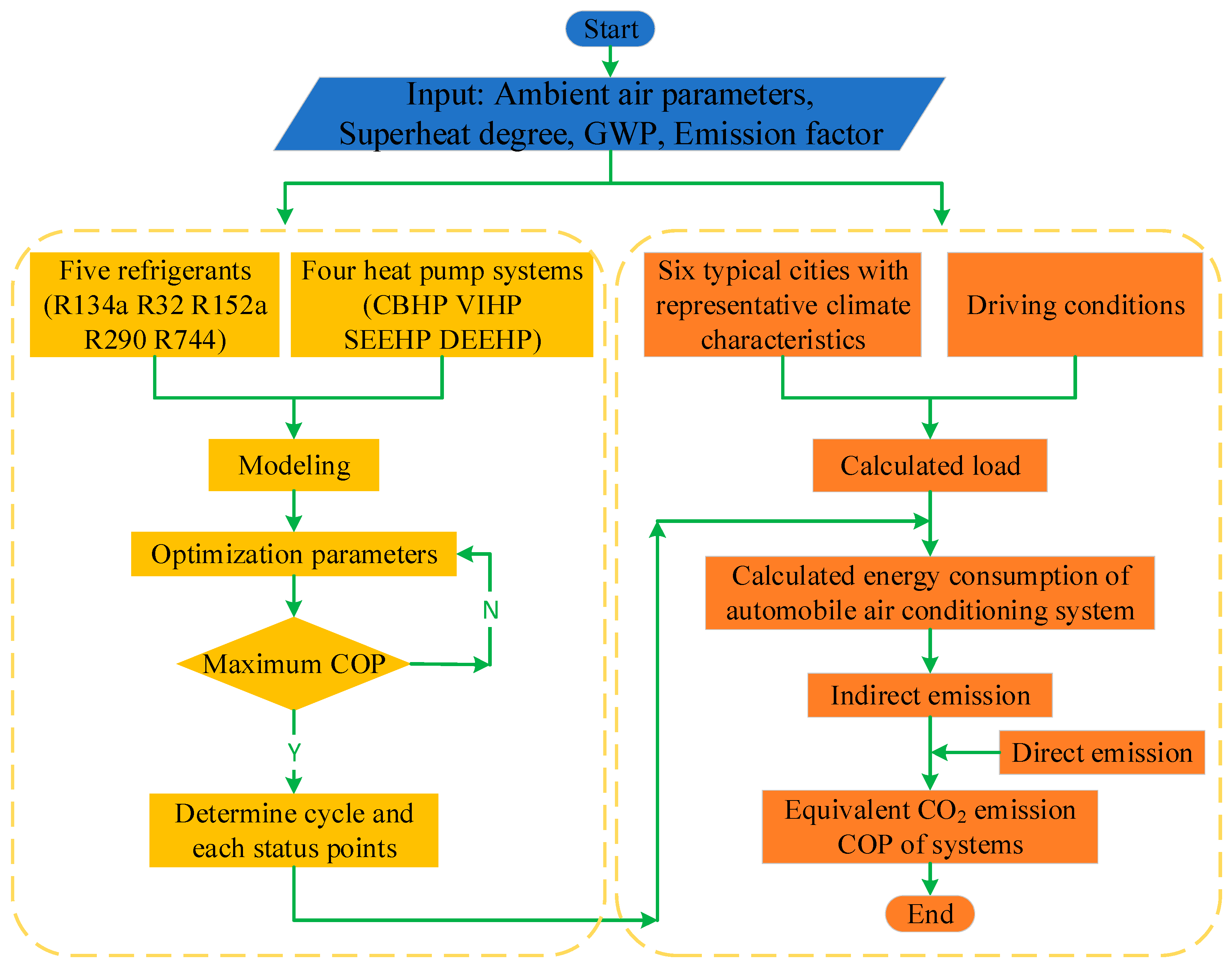
Finally, a flow diagram of the present model for assessment of heat pump systems is presented, as shown in Figure 6. The thermodynamic modeling was implemented in MATLAB R2021a, while refrigerant thermodynamic properties were calculated using REFPROP 10.0 (NIST).

4. Results and Discussion

4.1. Validation of Thermodynamic Model

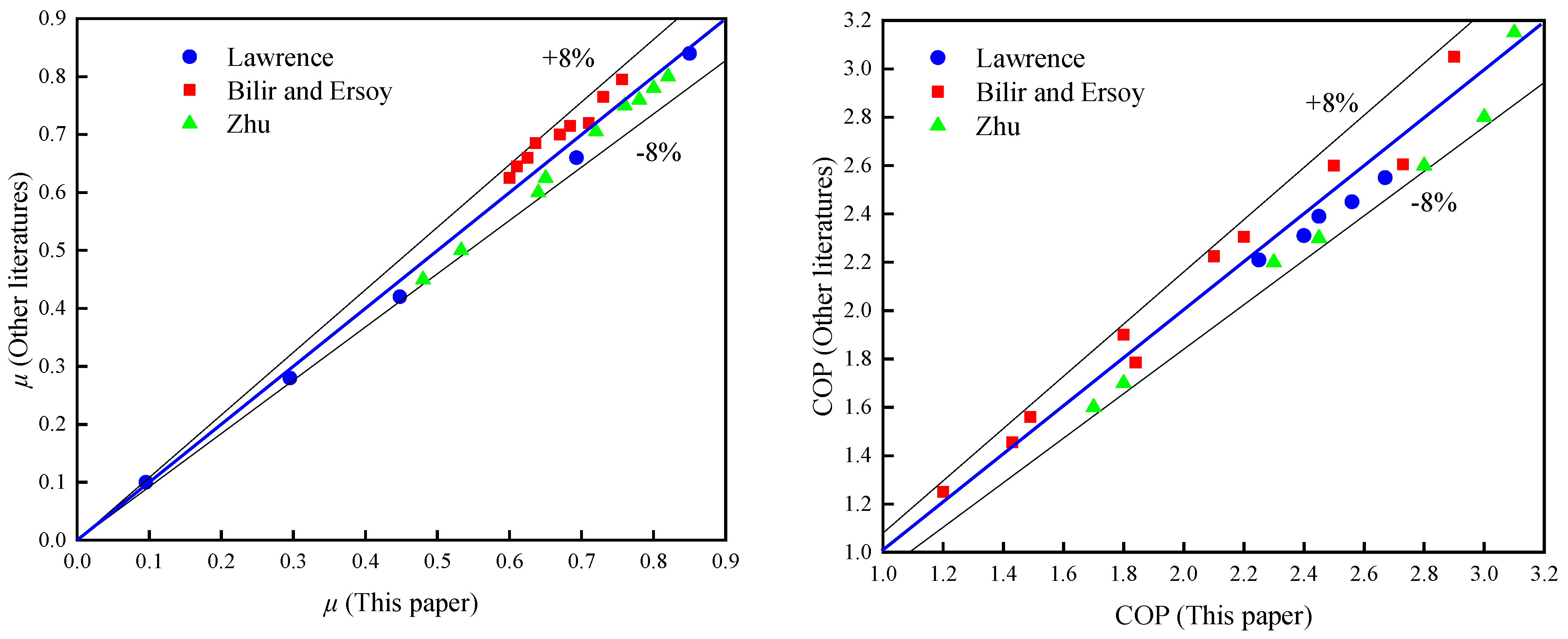
Two ejector-expansion system models are implemented in MATLAB and validated using experimental data from Lawrence and Elbel [65], Bilir and Ersoy [66] and Zhu et al. [67] to verify numerical reliability. When validating the model, the entrainment ratios and the COP values of SEEHP and DEEHP are simulated and compared with the corresponding reference data under the identical conditions. The validation results of the thermodynamic model are presented in Figure 7. Both entrainment ratios and COP values show less than 8% deviation, confirming the model’s reliability.

4.2. COP of Different Systems in Different Ambient Conditions

Figure 8 depicts COP variations across four systems using different refrigerants under varying ambient conditions. All refrigerants exhibit superior COP within moderate temperature bands compared to extreme ranges due to reduced indoor-outdoor temperature differentials. The system COP of R290 and R152a is slightly superior to that of other refrigerants.
For identical refrigerants and ambient conditions, the COP values of the investigated systems from highest to lowest are as follows: SEEHP, DEES, VIHP and CBHP. For all the refrigerants, the two ejector-expansion systems can enhance the COP effectively. The COP improvement of SEEHP and DEEHP can reach 10–30% and 7–15% compared with that of CBHP, respectively. This is because the expansion energy is recovered by the ejector, which brings two advantages. Firstly, the heat sink capacity of the evaporator is increased, because the nearly ideal isentropic processes inside the ejector lead to a higher specific enthalpy difference in the evaporator compared with the system with an enthalpic throttle valve. Secondly, the compression power is decreased because the compressor inlet pressure goes up owing to the ejector pressure lift effect. The compression power is further decreased owing to the compressor efficiency improvement caused by the lower compression ratio.
In particular, the pressure ratios of CBHP, SEEHP and DEEHP become greater than 10 in the COP calculation process for R134a, R152a and R290 at ambient conditions of C1 and C2 and were adjusted down to 10 to satisfy the limiting conditions for compressor operation. For R32, pressure ratio adjustment of CBHP, SEEHP and DEEHP is needed only at the ambient conditions of C1, as it has a higher heating capacity for heat pump applications. PTC is used for auxiliary heating. For VIHP, pressure ratio adjustment and PTC heating are unnecessary in all ambient conditions. Therefore, the COP in this paper is not an absolute thermodynamic cycle COP related to the working fluid but a COP that can be realized through the present technical level of the heat pump compressor. It is why the COP of VIHP is significantly lower than that of CBHP for R134a, R152a and R290 at ambient conditions of C1 and C2 and for R32 at the ambient conditions of C1.

4.3. Equivalent CO2 Emissions Evaluation Results

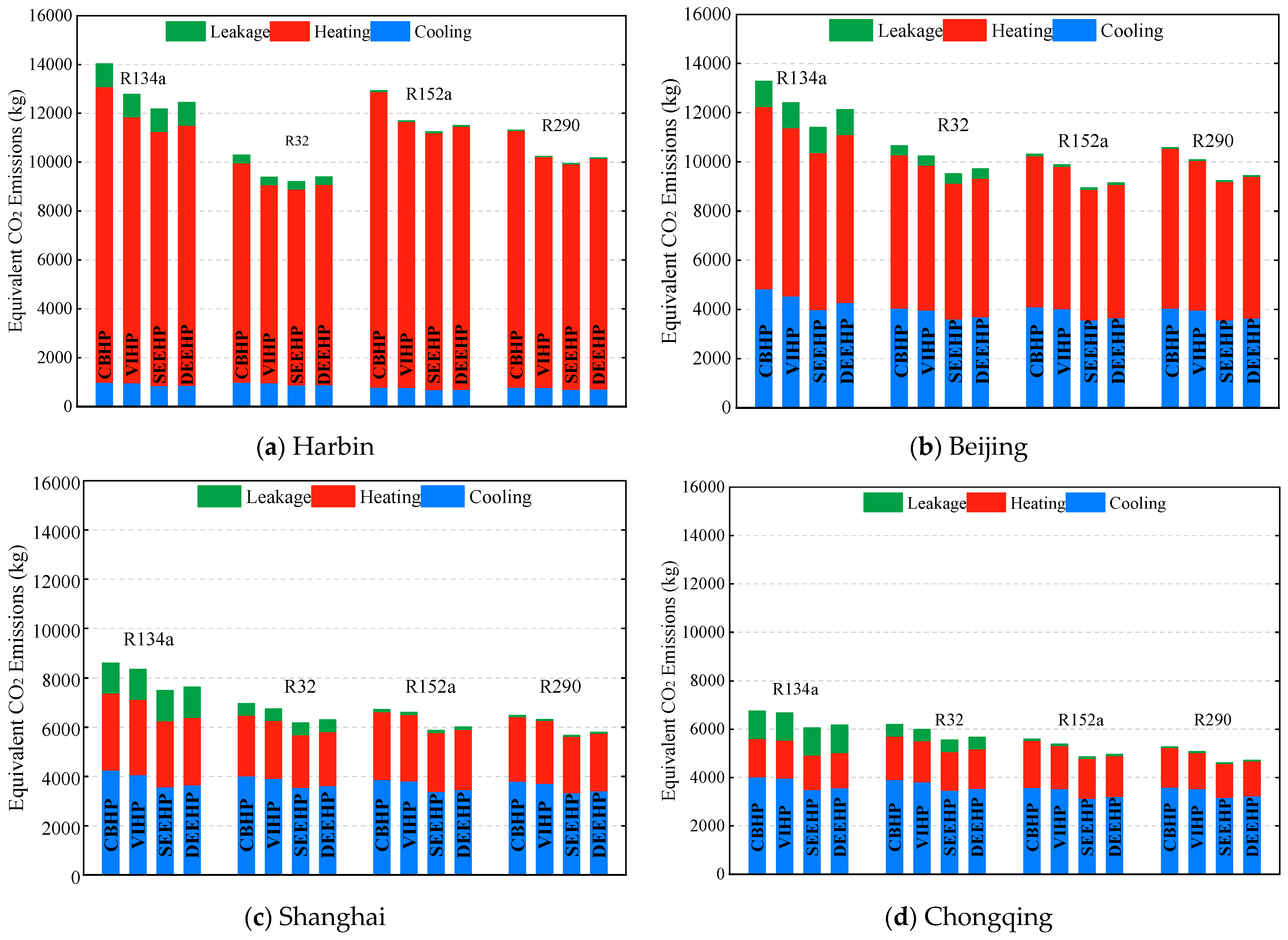
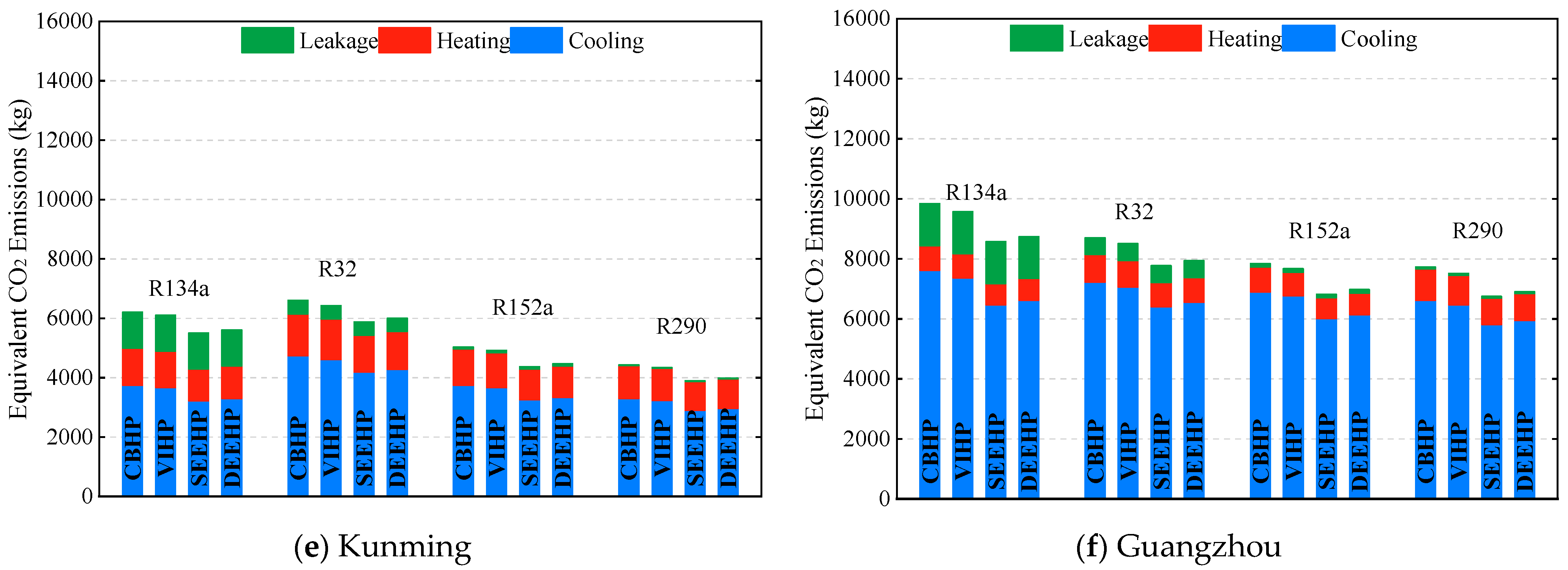
Figure 9 presents lifetime equivalent CO2 emissions for the four EV heat pump systems using investigated refrigerants across six Chinese cities. For the identical working fluid, the lifetime equivalent CO2 emissions of the investigated systems from highest to lowest are as follows: CBHP, VIHP, DEEHP and SEEHP for all the six typical cities. For any system, direct emission accounts for a tiny fraction of the total emission, such as R134a which has the highest GWP among the investigated refrigerants, and the direct emission accounts for less than 10% of the total emission. In Harbin, heating demands drive 85–94% of emissions, with cooling contributing 7–14%. SEEHP achieves the most pronounced reductions: 10–13% below CBHP and 2–5% below VIHP across refrigerants. DEEHP shows moderately lower emissions: 9–11% below CBHP and 2–5% below VIHP. In Beijing, balanced heating (55–61%) and cooling (35–45%) contributions yield significant SEEHP advantages: 11–14% reduction versus CBHP and 7–10% versus VIHP. DEEHP demonstrates 9–11% and 2–7% reduction over CBHP and VIHP, respectively. In Shanghai and Chongqing, cooling-dominated emissions (48–75%) show consistent ejector benefits: SEEHP lowers emissions by 8–11% relative to CBHP, while DEEHP achieves 3–4% reductions. In Kunming and Guangzhou, minimal heating contributions (8–26%) contrast with substantial cooling contributions (58–90%). Here, SEEHP lowers emissions by 9–11% relative to CBHP, with DEEHP providing 2–3% reductions. The superior performance of ejector systems, particularly SEEHP, stems from their ability to recover expansion work that would otherwise dissipate as entropy generation. The emission reduction differential between SEEHP and DEEHP reflects the thermodynamic limitation of dual evaporator configurations where partial flow still undergoes irreversible throttling.
Emission patterns vary significantly by region. Harbin exhibits the highest emissions due to extreme cold conditions necessitating substantial heating. Beijing shows the next highest emission levels, influenced by both climate factors and large scale of the local population and long runtime. Guangzhou ranks third due to extreme hot conditions necessitating substantial cooling. Shanghai and Chongqing demonstrate moderate emissions with balanced seasonal demands. Kunming presents the lowest emissions, benefiting from milder climates and reduced temperature differentials.
Low-GWP refrigerants achieve substantial emission reductions versus conventional R134a systems: R32/R290 systems reduce emissions by 24–27% in Harbin. R32/R152a/R290 systems achieve 18–25% reductions in Beijing. R152a/R290 systems lower emissions by 18–24% in Shanghai/Chongqing. R152a/R290 systems demonstrate 19–29% reductions in Kunming. R152a/R290 systems show 20–22% reductions in Guangzhou. Notably, R290 achieves the lowest absolute emissions across most regions despite only moderate COP improvements, highlighting the compound benefits of combining low-GWP refrigerants with advanced cycle architectures.

5. Conclusions and Remarks

Two ejector-expansion heat pump systems (SEEHP and DEEHP) for cabin cooling and heating of EVs are proposed. The lifetime equivalent CO2 emission of the systems is evaluated compared with CBHP and VIHP systems for R134a, R32, R290 and R152a as refrigerants in six typical cities in China. The results are as follows:
(1)
For all the refrigerants, the two ejector-expansion systems can enhance the COP effectively. The COP improvement of SEEHP and DEEHP can reach 10–30% and 7–15% compared with that of CBHP, respectively. For all the refrigerants, the COP improvements under moderate ambient conditions are significantly lower than those under higher or lower ambient conditions.
(2)
The ejector-expansion technique in EV heat pump systems can significantly lower the equivalent CO2 emission. The equivalent CO2 emission of the SEEHP decreases by about 9–14% and 2–10% compared with that of CBHP and VIHP, respectively. The equivalent CO2 emission of the DEEHP is reduced by about 2–11% compared with that of CBHP, and almost the same as that of VIHP.
(3)
R290 and R152a have relatively better performance in decreasing total equivalent CO2 emissions among the four working fluids due to their higher COP values. But the flammability risk is still the most troublesome problem in their application in EV heat pump systems. R32 is currently a viable alternative considering both CO2 emission reduction and flammability, but it has been on the list of HFCs to be cut in the Kigali Amendment.
(4)
The lifetime equivalent CO2 emission is affected significantly by the climate of the cities. The bitter-cold areas have the highest emissions, and warm areas have the lowest emissions. If bitter-cold areas are taken as the standard, the equivalent CO2 emissions decrease by approximately 2–21% cold areas, 21–57% in hot-summer/cold-winter areas, 32–61% in warm areas, and 5–39% in hot-summer/warm-winter areas, respectively. There is little difference among the areas for the SEEHP relative to CBHP in reducing CO2 emissions. But DEEHP is more remarkable in bitter-cold and cold areas. The equivalent CO2 emission of DEEHP relative to the corresponding CBHP decreases by about 9–11% in bitter-cold and cold areas, but this figure becomes 2–4% in other areas. These findings establish ejector-based systems as essential technologies for decarbonizing EV thermal management, particularly in extreme climates where conventional systems exhibit significant efficiency degradation.
To advance the proposed ejector-enhanced heat pump systems toward automotive implementation, four prioritized research directions will bridge theoretical innovation and commercial deployment. (1) Ejector geometry optimization: Employing multi-objective algorithms with CFD-validated models to refine nozzle throat diameters and diffuser angles, maximizing pressure recovery ratios while minimizing entropy generation across climatic operating points. (2) Intelligent control strategies: Leveraging reinforcement learning to dynamically coordinate compressor speed, ejector operation and valve actuation in response to real-time cabin/battery thermal transients. (3) Prototype validation: Through compact SEEHP/DEEHP modules, with bench and on-road testing under extreme conditions quantifying range extension, battery state-of-health preservation and flammability mitigation for low-GWP refrigerants. (4) Cross-system integration: Synergizing battery waste heat recovery via phase-change materials with vehicle-integrated photovoltaics to reduce indirect emissions. These technical advances will be paralleled by standardization initiatives and scalable manufacturing optimization, collectively accelerating sustainable thermal management solutions for next-generation EVs.

Author Contributions

Z.Z. (Zhenying Zhang): Project administration, conceptualization, methodology, reviewing. Y.W.: Writing—original draft, data acquisition, investigation. Z.Z. (Zhengdao Zhou): Data collation, software. Z.G.: Validation. L.C.: Reviewing, editing. M.Y.: Supervision, methodology, formal analysis, reviewing. All authors have read and agreed to the published version of the manuscript.

Funding

This work was funded by the Tangshan Science and Technology Planning Program (25130212B), the Tangshan Science and Technology Innovation Team Training Program (21130202D), and the S&T Program of Hebei (20474501D).

Data Availability Statement

The original contributions presented in this study are included in the article. Further inquiries can be directed to the corresponding author.

Conflicts of Interest

The authors declare no conflicts of interest.

Abbreviations

The following abbreviations are used in this manuscript:
CBHPConventional basic heat pump system
COPCoefficient of performance
DEEHPDual evaporator ejector-expansion heat pump system
ExVExpansion valve
FLTFlash tank
FwRVFour-way reversing valve
GLSGas–liquid separator
GWPGlobal warming potential
HFCsHydrofluorocarbons
HTEHigh-temperature evaporator
IHEIndoor heat exchanger
IPCCIntergovernmental Panel on Climate Change
ODPOzone depletion potential
OHEOutdoor heat exchanger
PTCPositive Temperature Coefficient
SEEHPSingle evaporator ejector-expansion heat pump system
TEWITotal Equivalent Warming Impact
TwVThree-way valve
VIHPVapor injection heat pump system
Greek
ηEfficiency
βEmission factor
μEntrainment ratio of the ejector
Variables
EEnergy consumption
hSpecific enthalpy
mMass flow rate
nLifetime in years
pPressure
QHeating or cooling load
TTemperature
xDryness
Subscripts
adAccidental leakage
capCapacity
comcompressor
condCondenser
ELEnd-of-life leakage
evaEvaporator
ftFlash tank
gcGas cooler
htHeat transfer
imIntermediate
inInlet
maAverage annual ambient temperature
motMotive
mtMaintenance leakage
outOutlet
rtRoutine leakage
sIsentropic
srSolar radiation
subSubcritical
sucSuction
totTotal
transTranscritical
venVentilation or infiltration

References

  1. Tie, S.F.; Tan, C.W. A Review of Energy Sources and Energy Management System in Electric Vehicles. Renew. Sustain. Energy Rev. 2013, 20, 82–102. [Google Scholar] [CrossRef]
  2. Zhang, Z.; Wang, J.; Feng, X.; Chang, L.; Chen, Y.; Wang, X. The Solutions to Electric Vehicle Air Conditioning Systems: A Review. Renew. Sustain. Energy Rev. 2018, 91, 443–463. [Google Scholar] [CrossRef]
  3. Lee, J.T.; Kwon, S.; Lim, Y.; Chon, M.S.; Kim, D. Effect of Air-Conditioning on Driving Range of Electric Vehicle for Various Driving Modes; SAE Technical Paper 2013-01-0040; SAE International: Warrendale, PA, USA, 2013. [Google Scholar]
  4. Farrington, R.; Rugh, J. Impact of Vehicle Air-Conditioning on Fuel Economy, Tailpipe Emissions, and Electric Vehicle Range: Preprint. Available online: https://media.runsular.com/me/6164bb0f8ba40ffb.pdf (accessed on 1 August 2015).
  5. Zhang, Z.; Li, W.; Zhang, C.; Chen, J. Climate Control Loads Prediction of Electric Vehicles. Appl. Therm. Eng. 2017, 110, 1183–1188. [Google Scholar] [CrossRef]
  6. Zhang, Z.; Liu, C.; Chen, X.; Zhang, C.; Chen, J. Annual Energy Consumption of Electric Vehicle Air Conditioning in China. Appl. Therm. Eng. 2017, 125, 567–574. [Google Scholar] [CrossRef]
  7. Peng, B.; Zhang, Y.; Zhang, P.; Ullah, H. Recent Advances on the Electric Vehicle Heat Pump Air Conditioning System. MENG 2021, 14, 354–365. [Google Scholar] [CrossRef]
  8. Li, K.; Luo, S.; Fan, L.; Hu, S.; Zhou, X.; Tu, R.; Zhang, H.; Jin, X.; Zhao, X.; Su, L. Investigation on the Performance and Characteristics of a Heat Pump System for Electric Vehicles under Extreme Temperature Conditions. Case Stud. Therm. Eng. 2021, 27, 101308. [Google Scholar] [CrossRef]
  9. Park, W.Y.; Shah, N.; Vine, E.; Blake, P.; Holuj, B.; Kim, J.H.; Kim, D.H. Ensuring the Climate Benefits of the Montreal Protocol: Global Governance Architecture for Cooling Efficiency and Alternative Refrigerants. Energy Res. Soc. Sci. 2021, 76, 102068. [Google Scholar] [CrossRef]
  10. Dai, B.; Qi, H.; Dou, W.; Liu, S.; Zhong, D.; Yang, H.; Nian, V.; Hao, Y. Life Cycle Energy, Emissions and Cost Evaluation of CO2 Air Source Heat Pump System to Replace Traditional Heating Methods for Residential Heating in China: System Configurations. Energy Convers. Manag. 2020, 218, 112954. [Google Scholar] [CrossRef]
  11. Direk, M.; Mert, M.S.; Soylu, E.; Yüksel, F. Experimental Investigation of an Automotive Air Conditioning System Using R444A and R152a Refrigerants as Alternatives of R134a. SV-JME 2019, 65, 212–218. [Google Scholar] [CrossRef]
  12. Yu, B.; Ouyang, H.; Shi, J.; Liu, W.; Chen, J. Evaluation of Low-GWP and Mildly Flammable Mixtures as New Alternatives for R410A in Air-Conditioning and Heat Pump System. Int. J. Refrig. 2021, 121, 95–104. [Google Scholar] [CrossRef]
  13. Yu, B.; Ouyang, H.; Shi, J.; Guo, Z.; Chen, J. Experimental Evaluation of Cycle Performance for New-Developed Refrigerants in the Electric Vehicle Heat Pump Systems. Int. J. Refrig. 2021, 129, 118–127. [Google Scholar] [CrossRef]
  14. Ning, Q.; He, G.; Xiong, G.; Sun, W.; Song, H. Operation Strategy and Performance Investigation of a High-Efficiency Multifunctional Two-Stage Vapor Compression Heat Pump Air Conditioning System for Electric Vehicles in Severe Cold Regions. Sustain. Energy Technol. Assess. 2021, 48, 101617. [Google Scholar] [CrossRef]
  15. Song, X.; Lu, D.; Lei, Q.; Cai, Y.; Wang, D.; Shi, J.; Chen, J. Experimental Study on Heating Performance of a CO2 Heat Pump System for an Electric Bus. Appl. Therm. Eng. 2021, 190, 116789. [Google Scholar] [CrossRef]
  16. Dong, J.; Wang, Y.; Jia, S.; Zhang, X.; Huang, L. Experimental Study of R744 Heat Pump System for Electric Vehicle Application. Appl. Therm. Eng. 2021, 183, 116191. [Google Scholar] [CrossRef]
  17. Wang, A.; Cao, F.; Yin, X.; Jia, F.; Fang, J.; Wang, X. Pseudo-Optimal Discharge Pressure Analysis of Transcritical CO2 Electric Vehicle Heat Pumps Due to Temperature Glide. Appl. Therm. Eng. 2022, 215, 118856. [Google Scholar] [CrossRef]
  18. Huang, Y.; Wu, X.; Jing, J. Research on the Electric Vehicle Heat Pump Air Conditioning System Based on R290 Refrigerant. Energy Rep. 2022, 8, 447–455. [Google Scholar] [CrossRef]
  19. Khalid Shaker Al-Sayyab, A.; Navarro-Esbrí, J.; Barragán-Cervera, A.; Mota-Babiloni, A. Heating and cooling challenges for electric vehicles: A comprehensive experimental study. Therm. Sci. Eng. Prog. 2024, 53, 102687. [Google Scholar] [CrossRef]
  20. Kwon, S.; Lee, D.; Chung, J.Y.; Maeng, H.; Kim, Y. Performance comparison of a direct heat pump using R1234yf and indirect heat pumps using R1234yf and R290 designed for cabin heating of electric vehicles. Energy 2024, 297, 131311. [Google Scholar] [CrossRef]
  21. Zhao, J.; Xiong, S.; Luo, Z.; Zhang, Y.; Yakubu, A.U.; Ye, X.; Wen, M.; Jiang, Q.; Xia, C. Study on performance characteristics of a novel R290-based integrated thermal management system for electric vehicles. Appl. Therm. Eng. 2025, 278, 127224. [Google Scholar] [CrossRef]
  22. Qin, F.; Xue, Q.; Albarracin Velez, G.M.; Zhang, G.; Zou, H.; Tian, C. Experimental Investigation on Heating Performance of Heat Pump for Electric Vehicles at −20 °C Ambient Temperature. Energy Convers. Manag. 2015, 102, 39–49. [Google Scholar] [CrossRef]
  23. Tang, J.; Zuo, C. Structural Analysis of Heat Pump Scroll Compressor for Electric Automobile Air Conditioning. J. Refrig. 2014, 35, 54–58. [Google Scholar]
  24. Lai, J.-C.; Luo, W.-J.; Wu, J.-Y.; Faridah, D.; Lin, C.-M.; Fasya, F.R.; Nuriyadi, M.; Ng, W.-B. Performance Analysis of Single-Stage Air Source Heat Pump Utilizing Indirect Vapor Injection Design. Adv. Mech. Eng. 2018, 10, 1–12. [Google Scholar] [CrossRef]
  25. Luo, W.-J.; Lai, J.-C.; Hsieh, M.-C.; Huang, I.-H. Performance Analysis of High-Temperature Two-Stage Compression Heat Pump with Vapor Injection Dynamic Control. Sens. Mater. 2020, 32, 4259–4275. [Google Scholar] [CrossRef]
  26. Li, W.; Liu, R.; Liu, Q.; Liu, Y.; Wang, D.; Xia, S.; Shi, J.; Chen, J. Upstream and Downstream Injection Effects on R134a Economized Vapor Injection Heat Pump System at Low Temperatures for Electric Vehicles. Int. J. Refrig. 2020, 120, 1–11. [Google Scholar] [CrossRef]
  27. Xu, Q.; Wu, J.; Guo, Z.; Xu, G.; Chen, Y.; Yang, H.; Xue, X. Experimental Investigation on Control Strategy of Electric Vehicle Heat Pump with Refrigerant Injection at Low Temperature. Int. J. Refrig. 2022, 138, 40–51. [Google Scholar] [CrossRef]
  28. Li, W.; Liu, R.; Liu, Y.; Wang, D.; Shi, J.; Chen, J. Performance Evaluation of R1234yf Heat Pump System for an Electric Vehicle in Cold Climate. Int. J. Refrig. 2020, 115, 117–125. [Google Scholar] [CrossRef]
  29. Peng, X.; Wang, D.; Wang, G.; Yang, Y.; Xiang, S. Numerical Investigation on the Heating Performance of a Transcritical CO2 Vapor-Injection Heat Pump System. Appl. Therm. Eng. 2020, 166, 114656. [Google Scholar] [CrossRef]
  30. Lee, S.; Chung, Y.; Jeong, Y.; Kim, M.S. Experimental Study on an Electric Vehicle Heat Pump System with Multi-Level Waste Heat Recovery Using a Vapor Injection Technique at Low Ambient Temperatures. Energy Convers. Manag. 2022, 267, 115935. [Google Scholar] [CrossRef]
  31. Sumeru, K.; Nasution, H.; Ani, F.N. A Review on Two-Phase Ejector as an Expansion Device in Vapor Compression Refrigeration Cycle. Renew. Sustain. Energy Rev. 2012, 16, 4927–4937. [Google Scholar] [CrossRef]
  32. Gullo, P.; Kærn, M.R.; Haida, M.; Smolka, J.; Elbel, S. A Review on Current Status of Capacity Control Techniques for Two-Phase Ejectors. Int. J. Refrig. 2020, 119, 64–79. [Google Scholar] [CrossRef]
  33. Zhang, Z.; Feng, X.; Tian, D.; Yang, J.; Chang, L. Progress in Ejector-Expansion Vapor Compression Refrigeration and Heat Pump Systems. Energy Convers. Manag. 2020, 207, 112529. [Google Scholar] [CrossRef]
  34. Pérez, B.P.; Carrillo, J.A.E.; de La Flor, F.J.S.; Lissén, J.M.S.; Navarro, A.M. Thermoeconomic Analysis of CO2 Ejector-Expansion Refrigeration Cycle (EERC) for Low-Temperature Refrigeration in Warm Climates. Appl. Therm. Eng. 2021, 188, 116613. [Google Scholar] [CrossRef]
  35. Ameur, K.; Aidoun, Z. Two-Phase Ejector Enhanced Carbon Dioxide Transcritical Heat Pump for Cold Climate. Energy Convers. Manag. 2021, 243, 114421. [Google Scholar] [CrossRef]
  36. Elbarghthi, A.F.A.; Dvorak, V.; Hafner, A.; Banasiak, K. The Potential Impact of the Small-Scale Ejector on the R744 Transcritical Refrigeration System. Energy Convers. Manag. 2021, 249, 114860. [Google Scholar] [CrossRef]
  37. Gao, Y.; He, G.; Cai, D.; Fan, M. Performance Evaluation of a Modified R290 Dual-Evaporator Refrigeration Cycle Using Two-Phase Ejector as Expansion Device. Energy 2020, 212, 118614. [Google Scholar] [CrossRef]
  38. Cao, X.; Liang, X.; Shao, L.; Zhang, C. Performance Analysis of an Ejector-Assisted Two-Stage Evaporation Single-Stage Vapor-Compression Cycle. Appl. Therm. Eng. 2022, 205, 118005. [Google Scholar] [CrossRef]
  39. Qin, X.; Zhang, Y.; Wang, D.; Chen, J. System Development and Simulation Investigation on a Novel Compression/Ejection Transcritical CO2 Heat Pump System for Simultaneous Cooling and Heating. Energy Convers. Manag. 2022, 259, 115579. [Google Scholar] [CrossRef]
  40. Oshitani, H.; Yamanaka, Y.; Takeuchi, H.; Kusano, K.; Ikegami, M.; Takano, Y.; Ishizaka, N.; Sugiura, T. Vapor Compression Cycle Having Ejector. U.S. Patent 7254961-B2, 13 August 2007. [Google Scholar]
  41. Talley, E. Hybrid Air Conditioning Systems Overview. Presented at the Spring 2011 ICAIA Conference, Hong Kong, China, 16–18 March 2011. [Google Scholar]
  42. Brodie, B.R.; Takano, Y.; Gocho, M. Evaporator with Integrated Ejector for Automotive Cabin Cooling; SAE Technical Paper 2012-01-1048; SAE International: Warrendale, PA, USA, 2012. [Google Scholar]
  43. Boumaraf, L.; Haberschill, P.; Lallemand, A. Investigation of a Novel Ejector Expansion Refrigeration System Using the Working Fluid R134a and Its Potential Substitute R1234yf. Int. J. Refrig. 2014, 45, 148–159. [Google Scholar] [CrossRef]
  44. Ünal, Ş. Determination of the Ejector Dimensions of a Bus Air-Conditioning System Using Analytical and Numerical Methods. Appl. Therm. Eng. 2015, 90, 110–119. [Google Scholar] [CrossRef]
  45. Ünal, Ş.; Erdinç, M.T.; Kutlu, Ç. Optimal Thermodynamic Parameters of Two-Phase Ejector Refrigeration System for Buses. Appl. Therm. Eng. 2017, 124, 1354–1367. [Google Scholar] [CrossRef]
  46. Zou, H.; Yang, T.; Tang, M.; Tian, C.; Butrymowicz, D. Ejector Optimization and Performance Analysis of Electric Vehicle CO2 Heat Pump with Dual Ejectors. Energy 2022, 239, 122452. [Google Scholar] [CrossRef]
  47. Yang, T.; Yang, Y.; Zou, H.; Tian, C.; Butrymowicz, D. Comprehensive performance evaluation on a transcritical CO2 ejector-expansion heat pump system. Appl. Therm. Eng. 2024, 254, 123697. [Google Scholar] [CrossRef]
  48. Ren, Z.; Song, Y.; Yin, X.; Cao, F.; Wang, Y. Energetic and driving range investigation of the ejector enhanced CO2 thermal management system used in electric vehicles. Energy 2025, 324, 135702. [Google Scholar] [CrossRef]
  49. Zhang, Z.; Tong, L.; Chang, L.; Chen, Y.; Wang, X. Energetic and Exergetic Analysis of an Ejector-Expansion Refrigeration Cycle Using the Working Fluid R32. Entropy 2015, 17, 4744–4761. [Google Scholar] [CrossRef]
  50. Wang, Y.; Zhou, Z.; Yang, M.; Chang, L.; Li, Y.; Zhang, Z. Parametric Effects of Mixing Channel Geometry on Entrainment Characteristics of Ejector in R410A Heat Pump Systems. Processes 2025, 13, 1933. [Google Scholar] [CrossRef]
  51. Deng, M.; Ma, R.; Lu, F.; Nie, Y.; Li, P.; Ding, X.; Yuan, Y.; Shan, M.; Yang, X. Techno-Economic Performances of Clean Heating Solutions to Replace Raw Coal for Heating in Northern Rural China. Energy Build. 2021, 240, 110881. [Google Scholar] [CrossRef]
  52. Bilir, N.; Ersoy, H.K. Performance Improvement of the Vapour Compression Refrigeration Cycle by a Two-Phase Constant Area Ejector. Int. J. Energy Res. 2009, 33, 469–480. [Google Scholar] [CrossRef]
  53. Zhang, Z.; Tian, L. Effect of Suction Nozzle Pressure Drop on the Performance of an Ejector-Expansion Transcritical CO2 Refrigeration Cycle. Entropy 2014, 16, 4309–4321. [Google Scholar] [CrossRef]
  54. Brunin, O.; Feidt, M.; Hivet, B. Comparison of the Working Domains of Some Compression Heat Pumps and a Compression-Absorption Heat Pump. Int. J. Refrig. 1997, 20, 308–318. [Google Scholar] [CrossRef]
  55. Yang, Y. Heating Carbon Emission and System Improvement for Rural Building of Beijing. Master’s Thesis, China Academy of Building Research, Beijing, China, 2019. [Google Scholar]
  56. Wang, A.; Yin, X.; Fang, J.; Cao, F. Refrigerant distributions and dynamic migration characteristics of the transcritical CO2 air conditioning system. Int. J. Refrig. 2021, 130, 233–241. [Google Scholar] [CrossRef]
  57. Lee, D.-Y.; Cho, C.-W.; Won, J.-P.; Park, Y.C.; Lee, M.-Y. Performance Characteristics of Mobile Heat Pump for a Large Passenger Electric Vehicle. Appl. Therm. Eng. 2013, 50, 660–669. [Google Scholar] [CrossRef]
  58. Neveu, D.; Claeys, J.P. Thermal Management of Electrical Vehicle—“VEGA/THOP” project. In Proceedings of the SAE Convergence 2010, Warrendale, PE, USA, 10 November 2010. [Google Scholar]
  59. Wu, J.; Zhou, G.; Wang, M. A Comprehensive Assessment of Refrigerants for Cabin Heating and Cooling on Electric Vehicles. Appl. Therm. Eng. 2020, 174, 115258. [Google Scholar] [CrossRef]
  60. Makhnatch, P.; Khodabandeh, R. The Role of Environmental Metrics (GWP, TEWI, LCCP) in the Selection of Low GWP Refrigerant. Energy Procedia 2014, 61, 2460–2463. [Google Scholar] [CrossRef]
  61. Zhang, Z.; Pan, L.; Wang, T.; Chen, J. Life Cycle Climate Performance Assessment of A/C System in Electric Vehicles. Automot. Eng. 2017, 39, 961–967. [Google Scholar] [CrossRef]
  62. Papasavva, S.; Hill, W.R.; Andersen, S.O. GREEN-MAC-LCCP: A Tool for Assessing the Life Cycle Climate Performance of MAC Systems. Environ. Sci. Technol. 2010, 44, 7666–7672. [Google Scholar] [CrossRef]
  63. Llopis, R.; Calleja-Anta, D.; Maiorino, A.; Nebot-Andrés, L.; Sánchez, D.; Cabello, R. TEWI Analysis of a Stand-Alone Refrigeration System Using Low-GWP Fluids with Leakage Ratio Consideration. Int. J. Refrig. 2020, 118, 279–289. [Google Scholar] [CrossRef]
  64. Zhang, X. Study on the Performance of a Heat Pump System Using R744-Based Natural Binary Mixture. J. Zhengzhou Univ. (Eng. Sci.) 2015, 36, P44–P48. [Google Scholar]
  65. Lawrence, N.; Elbel, S. Experimental Investigation of a Two-Phase Ejector Cycle Suitable for Use with Low-Pressure Refrigerants R134a and R1234yf. Int. J. Refrig. 2014, 38, 310–322. [Google Scholar] [CrossRef]
  66. Bilir Sag, N.; Ersoy, H.K. Experimental Investigation on Motive Nozzle Throat Diameter for an Ejector Expansion Refrigeration System. Energy Convers. Manag. 2016, 124, 1–12. [Google Scholar] [CrossRef]
  67. Zhu, Y.; Li, C.; Zhang, F.; Jiang, P.-X. Comprehensive Experimental Study on a Transcritical CO2 Ejector-Expansion Refrigeration System. Energy Convers. Manag. 2017, 151, 98–106. [Google Scholar] [CrossRef]
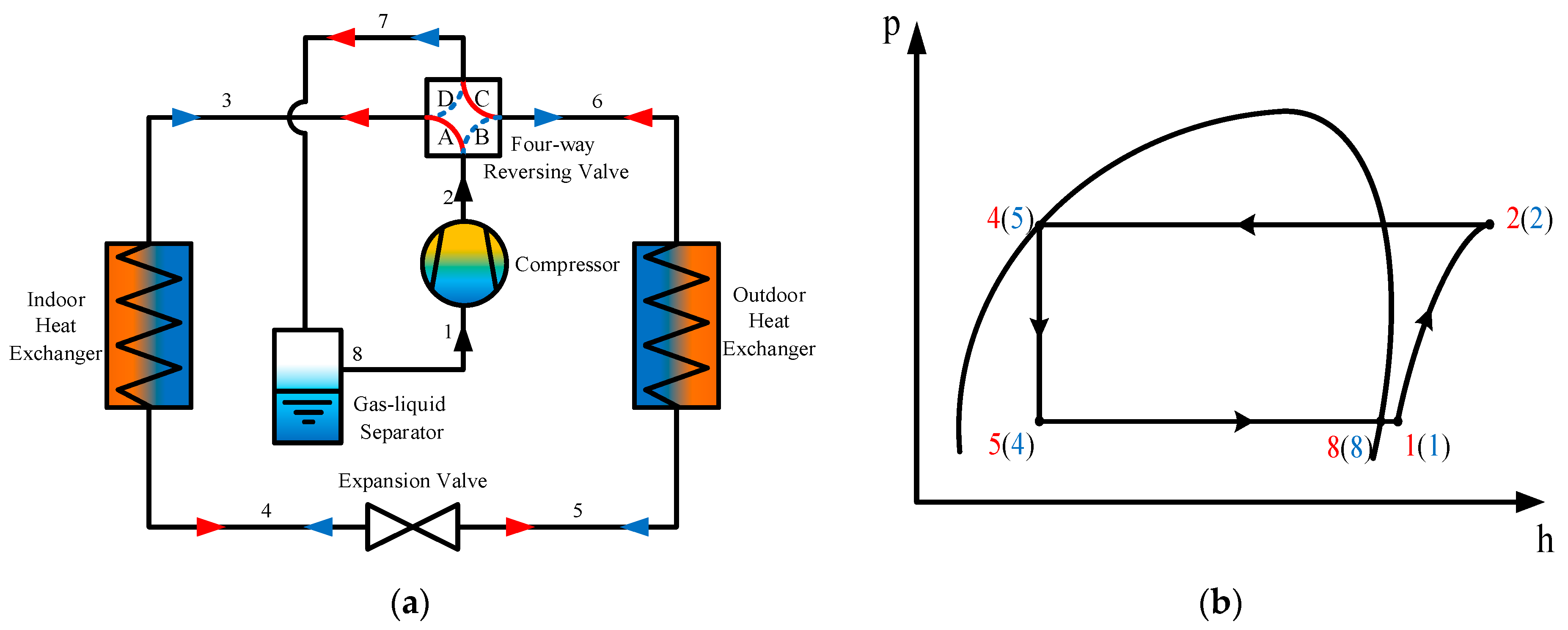
Figure 1. Conventional basic heat pump system (CBHP). (a) Schematic; (b) p-h diagram. The red arrow represents the heating operation. The blue arrow represents the cooling operation.
Wevj 16 00505 g001
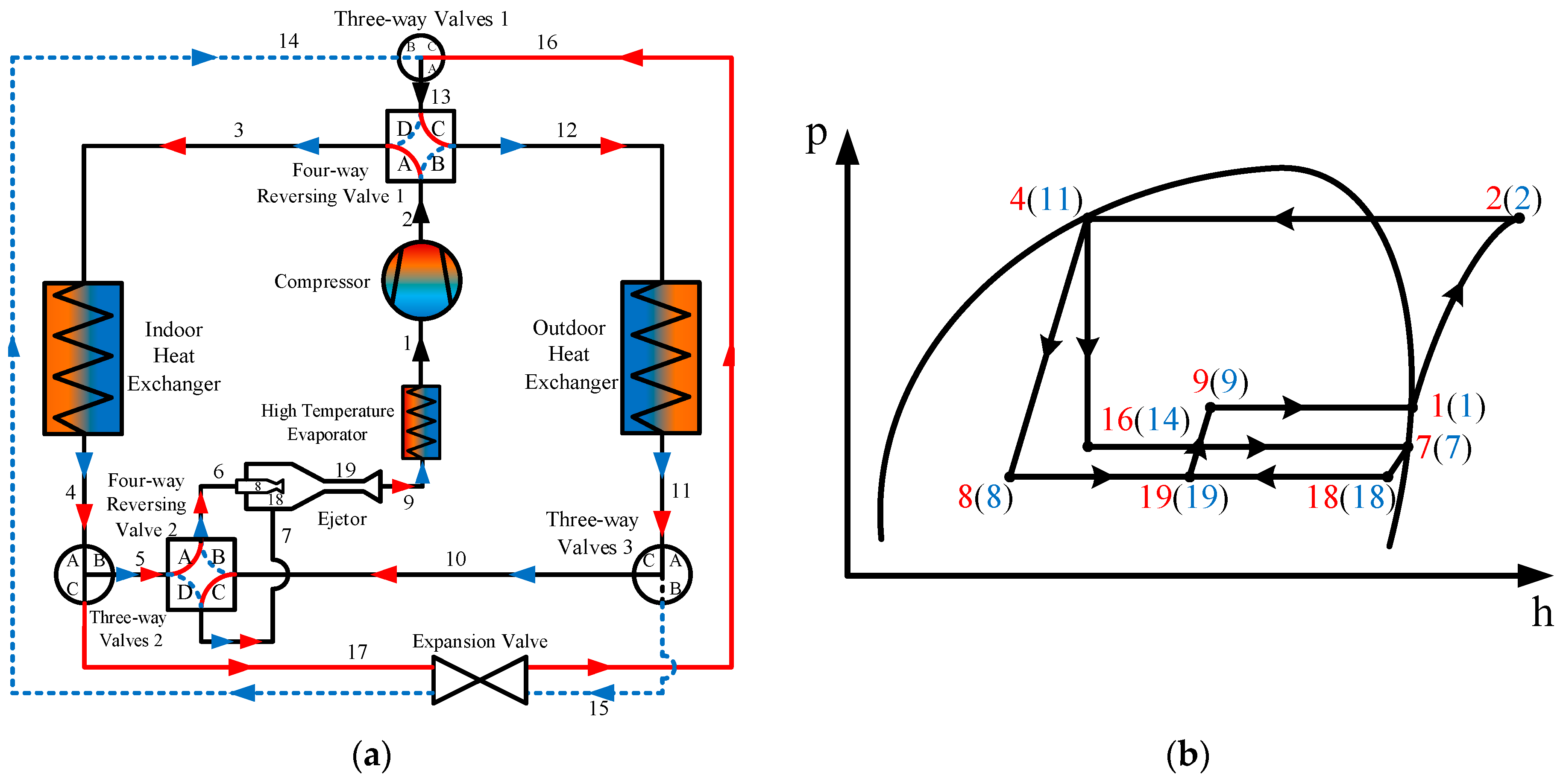
Figure 2. Vapor injection heat pump system (VIHP). (a) Schematic; (b) p-h diagram. The red arrow represents the heating operation. The blue arrow represents the cooling operation.
Wevj 16 00505 g002
Figure 3. Single evaporator ejector-expansion heat pump system (SEEHP). (a) Schematic; (b) p-h diagram. The red arrow represents the heating operation. The blue arrow represents the cooling operation.
Wevj 16 00505 g003
Figure 4. Dual evaporator ejector-expansion heat pump system (DEEHP). (a) Schematic; (b) p-h diagram. The red arrow represents the heating operation. The blue arrow represents the cooling operation.
Wevj 16 00505 g004
Figure 5. Ambient temperature profiles in representative Chinese cities.
Wevj 16 00505 g005
Figure 6. Flow chart of the present model for assessment of heat pump systems.
Wevj 16 00505 g006
Figure 7. Validation of the thermodynamic performance models.
Wevj 16 00505 g007
Figure 8. COP of each system in different ambient temperature ranges.
Wevj 16 00505 g008
Figure 9. Lifetime equivalent CO2 emissions of the four heat pump systems.
Wevj 16 00505 g009aWevj 16 00505 g009b
Table 1. Properties of the selected refrigerants.
RefrigerantsR134aR152aR290R32
Chemical formulaCF3CH2FCHF2CH3CH3CH2CH3CH2F2
Molecular mass (g/mol)102.0366.0544.152.02
Critical temperature (°C)101.1113.396.778.1
Critical pressure (MPa)4.074.524.245.8
Normal boiling point (°C)−26.1−25−42.2−51.6
GWP (100 years)14301243675
SafetyA1A2A3A2L
Lower flammability level (LFL) (% volume in air)None3.9%2.2%14%
Table 2. Average temperature, population and runtime of typical cities.
CityHarbinBeijingShanghaiChongqingKunmingGuangzhou
Average temperature (°C)5.013.016.718.415.422.5
Runtime (h/y)336675664493365631
Population (ten thousand)1066.5215424243102667.71530.6
Table 3. Proportion of vehicle speed range in CLTC-P driving cycle.
Speed (km∙h−1)0~1010~2525~5050~7575~100>100
Percentage30.2%21.3%27.1%15.1%4.3%2%
Table 4. Cabin parameters.
ComponentsHeat Transfer Area (m2)
Rear windshield0.88
Front windshield1.21
Side windows3.04
Roof 1.56
Floor 2.12
Table 5. Calculation results of thermal loads (kW).
Ambient Temperature (°C)HarbinBeijingShanghaiChongqingKunmingGuangzhou
C1−25~−152.26/////
C2−15~−51.63/////
C3−5~51.381.471.39/1.34/
C45~150.951.030.970.820.890.78
C515~252.432.722.462.282.352.25
C625~35/3.453.22.953.092.87
C1~C4 are heating mode, and C5 and C6 are refrigeration mode.
Table 6. Cabin air supply temperature, evaporation and condensation temperatures under different environmental conditions.
Ambient Temperature (°C)Air Conditioning ModeCabin Supply Temperature (°C)Evaporation Temperature (°C)Condensation Temperature (°C)
C1−25~−15Heating56−3070
C2−15~−5Heating46−2060
C3−5~5Heating38−1055
C45~15Heating28045
C515~25Refrigeration15540
C625~35Refrigeration7−550
Table 7. Emission factor of electric energy consumption (tCO2·MWh−1).
RegionNorthNortheastEastCentralNorthwestSouthern
Emission factor0.94191.08260.79210.85870.89220.8042
Disclaimer/Publisher’s Note: The statements, opinions and data contained in all publications are solely those of the individual author(s) and contributor(s) and not of MDPI and/or the editor(s). MDPI and/or the editor(s) disclaim responsibility for any injury to people or property resulting from any ideas, methods, instructions or products referred to in the content.