Abstract
To address the limitations of conventional magnetically coupled resonant wireless power transfer (MCR-WPT) systems in multi-frequency multi-load applications—specifically inadequate load power independence and high complexity inconstant-voltage/constant-current (CV/CC) control—this paper proposes a variable-structure dual-frequency dual-load wireless power transfer system by first establishing its mathematical model and implementing hybrid-frequency modulation for multi-frequency output, then developing an improved T/LCC hybrid resonant topology by deriving parameter design conditions for compensation network reconfiguration under CV/CC requirements, subsequently employing an orthogonal planar solenoid coupling mechanism and frequency-division demodulation to achieve load-independent power regulation across wide load ranges for enhanced stability, and finally constructing a 120 W dual-frequency dual-load prototype to validate the system’s CV/CC characteristics, where simulations and experimental results demonstrate stronger consistency with theoretical predictions.
1. Introduction
Magnetically coupled wireless power transfer (MC-WPT) technology has gained extensive application in recent years across transportation [1], electronic devices [2], and implantable medical devices [3] due to its safety and flexibility. To address diverse application scenarios, major wireless charging alliances have introduced standards such as Qi, A4WP, and PMA [4]. The variability among these standards and their differing power levels pose challenges to the compatibility of wireless charging platforms.
The core challenge in achieving reliable multi-frequency, multi-load wireless power supply lies in efficiently generating composite frequency excitation signals to drive multi-resonant circuits. The existing literature proposes various solutions. For instance, a recent study [5] has developed an MC-WPT system driven by multiple superimposed inverters, enabling multi-frequency mixed power output at the inverter terminals. Additionally, inverters operating at distinct frequencies are employed in [6] to simultaneously support receivers complying with different standards. Ref. [7] adopts a multi-transmitter and multi-receiver configuration, proposing a multiphase, multifrequency MC-WPT system capable of supplying multiple loads. This design effectively mitigates sensitivity to load misalignment and optimizes multi-objective power distribution and output stability through joint phase-frequency regulation. However, the parallel operation of multiple inverters across [5,6,7] complicates system architecture and induces nonlinear increases in power loss across transmission channels, hindering system miniaturization and practical implementation. While existing single-inverter systems can utilize fundamental and harmonic frequencies to establish multiple energy transfer paths, independent energy regulation across multiple receivers remains difficult as reported in [8,9].
To address this, a Multi-Frequency Multi-Amplitude (MFMA) modulation method is proposed in [10], which enhances DC voltage utilization by 44.88% via a phase optimization algorithm, albeit with complex modulation. In recent work [11], a Sinusoidal Pulse Width Superposition Modulation (SPWSM) method is introduced to enable independent receiver regulation; however, it substantially increases inverter switching frequency, leading to elevated power device losses. A delta-sigma modulation scheme is presented in [12] that significantly reduces switching frequency but requires complex online computation. Consequently, modulation methods for multi-frequency signals emerge as a critical issue in multi-load systems.
To meet the constant-voltage (CV)/constant-current (CC) requirements across diverse applications, numerous studies have proposed various compensation network topologies. For single-frequency multi-load systems, two primary approaches are typically employed: composite network design on the receiver side or transmitter side. A switched compensation network (SS/PS or SP/PP) using three switches to achieve CV/CC output was pioneered in [13]. In recent work [14], topology switching between TS/SP and S/SP configurations was introduced, enabling CC/CV output without DC-DC converters while reducing sensitivity to coupling coefficients through parameter decoupling; however, transient surges occur during switching. A variable static S-T/FC compensation topology is proposed in [15] to achieve CC/CV output via single-switch control, which simplifies switching circuitry but exhibits insufficient misalignment tolerance. As reported in [16], LCL-LCL and LCL-S composite topologies are utilized for CC/CV output, respectively, yet these designs suffer from parameter sensitivity and vulnerability to coil resistance.
For multi-frequency multi-load systems, a Multi-Frequency Resonant Compensation (MFRC) network was developed in [17] to achieve multi-resonant frequencies in multi-pickup WPT systems, with the aim of enhancing efficiency and reducing reactive power. However, its complex structure and challenging parameter design make it susceptible to cross-frequency interference, compromising output power. In recent research [18], a Superposed Dual-Frequency Modulation (SDFM) method was proposed for independent load power regulation, which employs an LC parallel resonant network on the secondary side to suppress cross-frequency interference, though its applicability is limited. Notably, the systems described in [17,18] fail to achieve CC/CV output characteristics.
To address this, a primary-side Multi-Frequency Constant-Current (MFCC) compensation network was introduced in [19], enabling the transmitter to operate as a constant-current source. This in turn allows receivers to deliver either CC or CV output to meet diverse load demands. Nevertheless, achieving such CC/CV output requires distinct receiver-side topologies, and the design of compensation network components remains complex. Recent work [20] has proposed a Hybrid-Frequency Multi-Load (HFML) WPT system, which can simultaneously power two independently regulated loads via a primary-side hybrid-frequency compensation network. However, this approach is confined to dual-frequency dual-load scenarios and offers only a limited range of load regulation.
In summary, to achieve simultaneous multi-frequency output in multi-frequency multi-load MCR-WPT systems while minimizing system volume, this work employs hybrid-frequency superposition modulation, enabling concurrent transmission of multiple frequency signals to support diverse application scenarios. The transmitter incorporates a modified T-type topology integrating series resonant compensation with LCC resonant compensation, while the receiver side adopts an LCC structure, permitting effective regulation across wide load ranges and achieving independent power regulation. This approach enhances flexibility in power distribution among different receivers.
2. System Topology and Modeling
Conventional multi-frequency multi-load magnetically coupled resonant wireless power transfer (MCR-WPT) systems transmit electrical energy through resonant magnetic coupling. As illustrated in Figure 1, the system primarily comprises a DC power source, high-frequency inverter circuit, transmitter-side resonant network, rectifiers, receiver-side resonant networks, and loads. The DC power source is converted into a high-frequency AC source through the inverter. After partial reactive power compensation via the primary-side hybrid compensation network, electrical energy is transferred from the transmitting coil to receiving coils. Each receiving coil incorporates a filtering circuit; when the filtering network exhibits effective frequency-selective characteristics, it can selectively receive signals at different frequencies. Finally, rectifiers supply power to respective loads, achieving reliable multi-frequency multi-load power delivery.
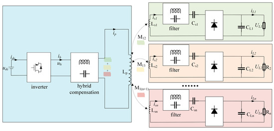
Figure 1.
Multi-Load variable-structure wireless power transfer (WPT) system.
For medium-to-low-power charging systems, a single transmitting coil may be employed on the primary side, significantly simplifying system architecture. Notably, the transmitter and receiver designs enable stable constant-current (CC) and constant-voltage (CV) outputs without requiring real-time communication, thereby satisfying diverse load requirements. This approach not only enhances system flexibility and adaptability but also provides a reliable power transfer solution for practical applications.
To simplify system analysis, a dual-frequency dual-load MCR-WPT system is proposed as illustrated in Figure 2 below.
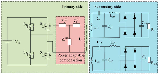
Figure 2.
Dual-frequency dual-load MCR-WPT system.
2.1. Hybrid-Frequency Modulation Methodology
To satisfy the frequency requirements of diverse loads, this design employs a hybrid-frequency-modulation-based PWM control method as depicted in Figure 3. The implementation utilizes a triangular carrier signal, with the modulation signal being a composite waveform formed by superimposing sinusoidal waves whose amplitudes and frequencies are independently adjustable. These sinusoidal components are expressed in Equation (1).
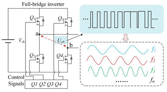
Figure 3.
Hybrid-frequency modulation methodology.
In Equation (1), ur1(t), ur2(t),…, urn(t) represent n distinct modulation signals, while ur(t) denotes the composite modulated signal. Here, a1, a2,…, an correspond to the amplitudes of individual modulation components, and f1, f2,…, fn align with the inherent resonant frequencies of respective receiver-side circuits.
For dual-frequency dual-load WPT systems, a novel hybrid-frequency modulation method is proposed. This approach employs two modulation signals with equal amplitude and opposite polarity, which are compared against a high-frequency triangular carrier wave. The comparison generates complementary driving signals for switch pairs (Q1 and Q4, Q2 and Q3), thereby enabling the inverter to produce pulsed outputs. This mechanism efficiently converts DC input into AC power with programmable frequency and amplitude, offering both flexible control strategies and high operational efficiency.
To elucidate the operating principles, this work demonstrates a hybrid modulation scheme combining 59 kHz and 151 kHz sinusoidal components. Figure 4 illustrates the modulation mechanism:
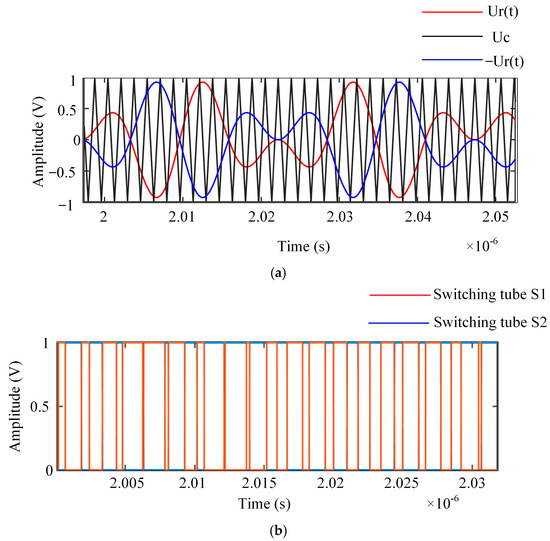
Figure 4.
Hybrid Modulated Sinusoidal Pulse Width Modulation (SPWM) waveform. (a) Comparative analysis of hybrid waveform vs. carrier signa; (b) output pulse sequences of upper/lower switches in front bridge arm.
2.2. Compensation Network Design Philosophy
The circuit structure: Among the four fundamental compensation topologies in inductive wireless power transfer (WPT) systems, the Series–Series (S-S) compensation network exhibits superior structural simplicity compared to alternative configurations. This study therefore prioritizes the analysis of constant-current (CC) and constant-voltage (CV) compensation design principles based on the S-S topology, ultimately proposing a hybrid compensation network architecture capable of achieving dual-mode CC/CV operation. Figure 5 illustrates the equivalent circuits of the S-S-compensated WPT system under distinct excitation conditions. The analytical framework initiates with parametric modeling of the S-S network’s inherent characteristics, followed by systematic derivation of CC/CV constraint equations. This methodology establishes theoretical foundations for subsequent integration of hybrid compensation components while maintaining compatibility with conventional S-S configuration advantages.
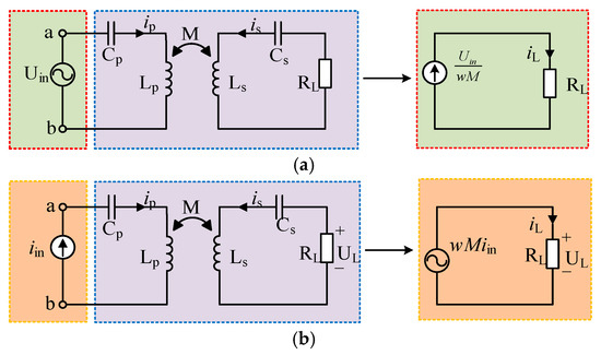
Figure 5.
Equivalent circuit diagram of S-S wireless power transfer system. (a) Voltage-source input; (b) current-source input.
When terminals ab are configured as a voltage-source input and the circuit operates in resonant state, the current gain HVI of the system can be derived from (KVL) as follows:
where IL denotes the RMS value of the output current and Uin represents the RMS value of the input voltage. Equation (2) reveals that the S-S compensated system achieves constant-current output when maintaining fixed operating frequency, mutual inductance coefficient, and input voltage amplitude.
Analogously, when terminals ab are configured as a current-source input under resonant operation, the voltage gain HIV can be derived from KVL:
In Equation (3), Iin represents the RMS value of the input current, and UL denotes the RMS value of the output voltage. The analysis demonstrates that the S-S compensated system achieves constant-voltage (CV) output when maintaining fixed operating frequency, mutual inductance coefficient, and input current amplitude.
In conclusion, the constant-voltage/constant-current (CV/CC) regulation of WPT systems can be realized through active control of input port power characteristics. This paper proposes the topology shown in Figure 6, which incorporates a variable-structure compensation network between the voltage source and terminals ab. This network dynamically reconfigures its parameters to meet system requirements for CV/CC operation, thus enabling adaptive impedance matching across varying load conditions while preserving resonant energy transfer efficiency.
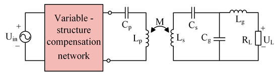
Figure 6.
Variable-structure wireless power transfer (WPT) system.
3. Analysis of Constant-Voltage/Constant-Current Characteristics in Dual-Frequency Dual-Load MCR-WPT Systems
The proposed dual-frequency dual-load MCR-WPT system employs a modified T-type resonant compensation network at the transmitter side. This network equivalently functions as S and LCC topologies at different operating frequencies. The secondary side adopts an LCC compensation structure to achieve load-independently regulated constant-current (CC) or constant-voltage (CV) output. Figure 7 illustrates the circuit schematic of this dual-frequency dual-load WPT system.
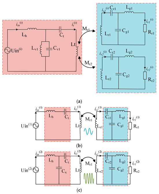
Figure 7.
Circuit schematic of dual-frequency dual-load WPT System. (a) Integrated architecture of dual-frequency dual-load system; (b) S-LCC equivalent circuit; (c) LCC-LCC equivalent circuit.
3.1. Analysis of Constant-Voltage Characteristics
The sinusoidal fundamental components Uin(1) and Uin(2), derived from the DC voltage source Vin via inversion, are expressed as:
The equivalent loads Rr1 and Rr2, for the uncontrolled bridge rectifiers and their respective loads, are given by:
The hybrid compensation resonant network manifests distinct circuit configurations at operating frequencies f1 and f2. When operating at frequency f1, the primary side achieves full series resonance, satisfying the resonant conditions specified in Equation (6):
In Equation (6), the system reduces to an S-LCC equivalent topology at f1, as illustrated in Figure 7b. The receiver-side parameters are designed as follows:
Applying mutual inductance theory and Kirchhoff’s voltage law, the voltage–current relationship matrix for the primary transmitter and secondary receiver loop 1 is formulated in Equation (8):
where i = 1, 2 corresponds to frequencies f1, f2 of receiver loops/loads, respectively; iin(i) is the Inverter output current; it(i), is1(i), and is2(i) are the Transmitter, Receiver 1, and Receiver 2 currents, respectively; ir1(i) and ir2(i) are the Load 1 and Load 2 currents, respectively; and wi, Z1, and Z2 are the angular frequency and input impedances of receiver loops, respectively.
The detailed impedance formulations are as follows:
To mitigate cross-frequency interference, the design ensures , allowing cross-frequency interference to be neglected. Solving the simultaneous equations yields the transmitter loop current and the output current/voltage expressions for receiver loop 1:
where Zref1 and Zref2 denote the reflected impedances of loops 1 and 2, respectively.
In summary, the output voltage of load 1 remains independent of its load value RL1, demonstrating the achievement of constant-voltage (CV) output.
3.2. Analysis of Constant-Current Characteristics
When the system operates at frequency f2, it reduces to an LCC-LCC equivalent topology as depicted in Figure 7c. The parameter design for the hybrid compensation network’s LCC topology follows Equations (13) and (14):
Additionally, the receiver-side parameters at f2 are expressed in Equation (15):
Applying mutual inductance theory and Kirchhoff’s voltage law, the voltage–current relationship matrix for the primary transmitter and secondary receiver loops is formulated in Equation (16):
Similarly, the design ensures , allowing cross-frequency interference to be neglected. Solving the simultaneous equations yields the transmitter loop current and the output current/voltage expressions for receiver loop 2:
where Zref1 and Zref2 denote the reflected impedances of Loop1 and Loop2, respectively.
The output current of load 2 remains independent of its load value RL2, demonstrating the achievement of constant-current (CC) output.
3.3. Load-Independent Power Analysis
Equations (12) and (17) reveal the critical importance of coupling mechanism design in the system. To decouple cross-coupling effects on the secondary side, conventional approaches typically employ double-d quadrature (DDQ) coils [21] and bi-polar (BP) coils [22]. However, existing solutions exhibit limitations including the inability to simultaneously achieve tolerance to both translational misalignment and angular deviation, along with cross-imbalanced coupling among multiple transmitting coils. To overcome these limitations, this paper proposes a grid-pattern planar solenoid coil as illustrated in Figure 8.
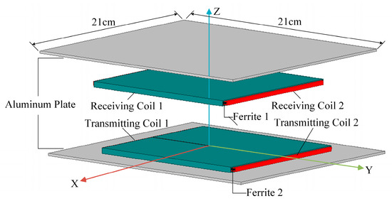
Figure 8.
Three-dimensional structural diagram of magnetic coupling mechanism.
The effective coupling coefficient keff is
The anti-misalignment performance of the magnetic coupling mechanism can be quantified using the Coupling Coefficient Retention Ratio (CCRR), defined as
where keff1 is the equivalent coupling coefficient at the aligned position, and keff2 is the equivalent coupling coefficient at the misaligned or tilted position.
Employing orthogonal winding configurations on both transmitter and receiver sides, with the transmitting coils connected in series to deliver target frequencies, enables receiver decoupling and reduces cross-frequency interference. The corresponding magnetic flux distribution of this coupling mechanism is illustrated in Figure 9.
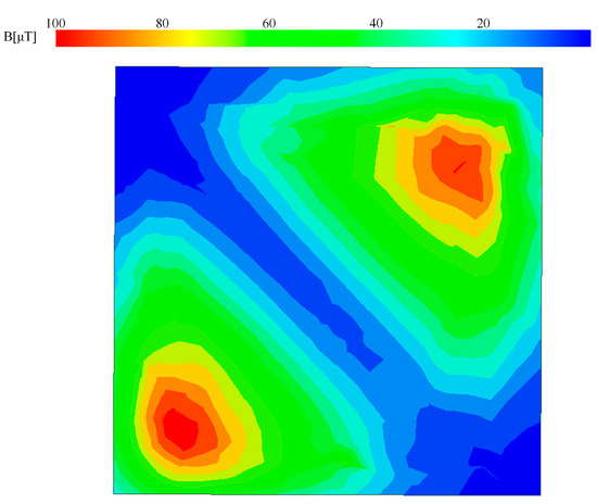
Figure 9.
Receiver-side magnetic flux distribution.
Conventional coils exhibit limited misalignment tolerance due to their dual-flux-loop design, where reverse magnetic fluxes flowing through the coil counteract each other during planar displacement. Figure 10a illustrates the flux distribution when the coupling mechanism is perfectly aligned, displaying a single-flux-loop configuration in cross-section. During planar misalignment (Figure 10b), flux redistribution occurs without cancellation phenomena, resulting in gradual coupling coefficient reduction.
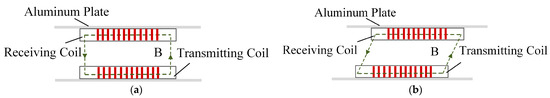
Figure 10.
Cross-sectional magnetic flux of coupling mechanism. (a) Perfect alignment position; (b) translational misalignment.
While individual Flat Spiral Planar (FSP) coils demonstrate misalignment resistance along their winding direction, the orthogonal dual-coil structure enables Grid-pattern Flat Spiral Planar (GFSP) coils to achieve effective tolerance in both X- and Y-axis directions. The parameter design for the proposed magnetic coupling mechanism is shown in Table 1 as follows:

Table 1.
Parameter value assignment for magnetic coupling mechanism technical context.
Finite element analysis (FEA) simulations of the magnetic coupling mechanism at varying receiver positions yield the magnetic flux distribution depicted in Figure 11.
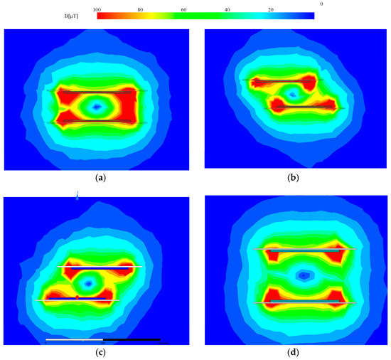
Figure 11.
Magnetic flux distribution under translational and angular displacement. (a) Perfectly aligned configuration; (b) 80 mm displacement along X-axis; (c) 80 mm displacement along Y-axis; (d) 80 mm displacement along Z-axis.
Figure 11b,c present the magnetic field distribution at the receiver side with an 80 mm offset along the X- and Y-axis directions, respectively. The figure shows that the magnetic field at the receiver side converges toward the transmitter side, gradually intensifying from the offset direction toward the transmitter side, thereby mitigating the increase in magnetic reluctance during misalignment. Due to the GFSP magnetic coupling mechanism’s orthogonal grid-distributed dual-coil structure, it exhibits anti-misalignment capability in both the X- and Y-axis directions. Figure 11d presents the magnetic field distribution at the receiver side with an 80 mm offset along the Z-axis direction. The figure shows that the magnetic field remains uniformly distributed, indicating that the GFSP magnetic coupling mechanism possesses certain anti-misalignment capability in the Z-axis direction.
Figure 12a–c, respectively, illustrate the variation patterns of Mr1, Mr2, Mr1r2, Lp, Lr1, and Lr2 under X-axis, Y-axis, and Z-axis misalignments. The cross-mutual inductances Mr1r2 consistently remain at zero throughout the entire range.
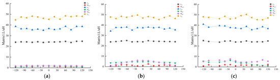
Figure 12.
Analysis of different axial misalignment conditions. (a) Misalignment in X-axis/mm; (b) Misalignment in Y-axis/mm; (c) Misalignment in Z-axis/mm.
Figure 13a–c, respectively, demonstrate the variation characteristics of the Coupling Coefficient Retention Ratio (CCRR) under X-axis, Y-axis, and Z-axis misalignments. The results reveal the following:
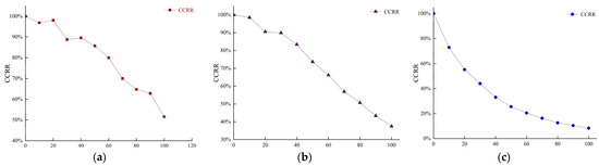
Figure 13.
CCRR analysis under different axial misalignments. (a) Misalignment in X-axis/mm; (b) Misalignment in Y-axis/mm; (c) Misalignment in Z-axis/mm.
- 1.
- When subjected to X-axis or Y-axis misalignment, the CCRR consistently exceeds 50% within a ±100 mm displacement range;
- 2.
- Under Z-axis misalignment conditions, the CCRR remains above 50% within a ±30 mm range.
Consequently, the proposed magnetic coupling mechanism in this study exhibits robust anti-misalignment capability when experiencing X-axis or Y-axis displacements.
The predominant power losses occur in the primary-side and secondary-side coils, primarily attributable to their internal resistances. The total system power loss is formulated as follows:
Here, and denote the power loss components at frequencies f1 and f2 in the transmitter and receiver sides, respectively, while include coil losses, inverter losses, capacitor losses, and other components. By synthesizing Equations (15)–(19), the transmission efficiency from the transmitter to the receiver is derived as follows:
4. Simulation and Experimental Validation
To validate the operational performance of the designed dual-frequency dual-load magnetically coupled resonant wireless power transfer (MCR-WPT) system, the system was first simulated under operating frequencies of f1 = 59 kHZ and f2 = 151 kHz, with the resonant frequencies of the two secondary-side receiver circuits correspondingly set to 59 kHz and 151 kHz. A comprehensive circuit model was established using the MATLAB/Simulink platform to analyze system dynamics. Simultaneously, a laboratory prototype was constructed to experimentally verify the theoretical framework, ensuring alignment between simulation predictions and practical outcomes. Key parameters for both simulation and experimental setups, including coil geometries, compensation network configurations, and load specifications, are systematically summarized in Table 2.
Table 2.
WPT system parameter descriptions.
The system employs a dual-frequency superposition modulation strategy to synthesize composite signals from two distinct frequency components, which are then used to control the switching patterns of the high-frequency full-bridge inverter. This enables the generation of a dual-frequency composite voltage waveform at the inverter output terminals. Leveraging the principles of electromagnetic induction coupling and resonant synchronization, the secondary-side receiver circuits autonomously extract power through frequency-selective resonant networks. Consequently, simultaneous wireless power delivery to two independent loads operating at disparate frequencies (f1 and f2) is achieved within a single MCR-WPT architecture, demonstrating robust dual-band operational capability.
The output voltage waveform of the high-frequency inverter, along with its output current waveform and the current waveforms of the two receiver circuits operating at distinct resonant frequencies, are depicted in Figure 14. Additionally, to validate the efficacy of dual-frequency power transmission, Figure 14 provides the corresponding current spectral analysis diagrams of the inverter and the two load circuits, derived from simulation results, which explicitly demonstrate the frequency-selective energy transfer characteristics and spectral isolation between the 59 kHz and 151 kHz operating bands.
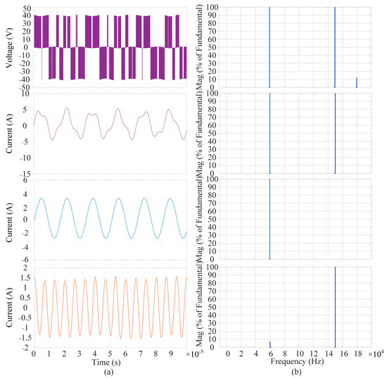
Figure 14.
Simulated waveforms of the inverter output and Fast Fourier Transform (FFT) analysis results. (a) Output voltage and current waveforms of the high-frequency inverter and dual-frequency loads; (b) FFT spectral characteristics of the inverter and load currents.
The experimental waveforms of the output voltage and current from the transmitting coil are shown in Figure 14. It can be observed that the experimental results align well with theoretical predictions, demonstrating that the transmitter’s parameter design effectively enables the transmission of dual-frequency composite waves.
To intuitively demonstrate that the designed dual-frequency dual-load system possesses constant-voltage (CV) and constant-current (CC) characteristics, the transient response of the output power in both receiving circuits was analyzed.
As shown in Figure 15, the blue curve represents the voltage of Load 1, while the red curve represents the current of Load 1. In the system, at one time, Load 2 was maintained at 20 Ω, while Load 1 was switched from 20 Ω to 10 Ω. The corresponding waveform is illustrated in Figure 16a. The voltage waveform changed from 34 V to approximately 34 V, exhibiting minimal variation and quickly stabilizing. The current waveform increased from 1.7 A to 3.4 A. Both voltage and current waveforms of Load 1 maintained good quality before and after the switching. The post-switching waveform, shown in Figure 16b, operates at a frequency of 59 kHz.
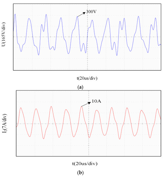
Figure 15.
Transmitting waveform. (a) Transmitting voltage waveform; (b) transmitting current waveform.
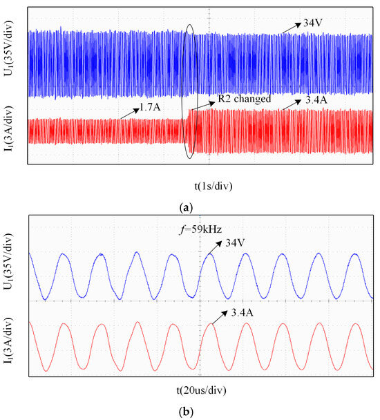
Figure 16.
Waveform of Load 1. (a) Output waveform when Load 1 changed; (b) zoomed-in view of the waveform at f1 = 59 kHz.
Similarly, Figure 17 displays the blue curve as the voltage of Load 2 and the red curve as the current of Load 2. At another time, Load 1 was fixed at 20 Ω, while Load 2 was switched from 20 Ω to 10 Ω. The resulting waveform is presented in Figure 17a. The current waveform varied from 2.1 A to around 2.1 A, with negligible fluctuation and rapid stabilization. The voltage waveform increased from 40 V to 21 V. The voltage and current waveforms of Load 2 also maintained high quality during the transition. The pre-switching waveform, depicted in Figure 17b, operates at a frequency of 151 kHz.
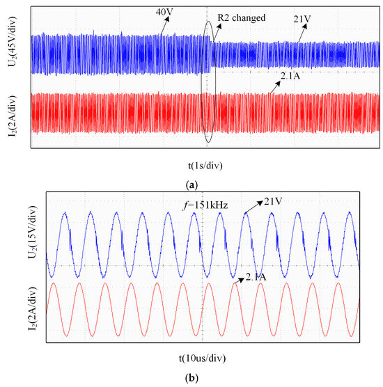
Figure 17.
Waveform of Load 2. (a) Constant-current (CC) characteristic waveform; (b) zoomed-in view of the waveform at f2 = 151 kHz.
In conclusion, the proposed dual-frequency dual-load MC-WPT system can achieve both constant-voltage and constant-current output.
In the system, at one time, while maintaining Load 2 at a constant value of 20 Ω, Load 1 is switched from 20 Ω to 10 Ω. The corresponding voltage and current waveforms of Load 1, along with the voltage waveform of Load 2, are shown in Figure 18. The blue and red curves represent the voltage and current of Load 1, respectively, while the green curve represents the voltage of Load 2.
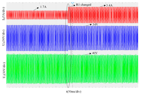
Figure 18.
Output waveform when Load 1 changed.
As can be seen from Figure 18, when Load 1 is switched at one time, Load 2’s voltage remains stable at 40 V, indicating that the switching of Load 1 has almost no effect on Load 2.
In the system, at another time, while maintaining Load 1 at a constant value of 20 Ω, Load 2 is switched from 20 Ω to 10 Ω. The corresponding voltage and current waveforms of Load 2, along with the voltage waveform of Load 2, are shown in Figure 19. The blue and red curves represent the voltage and current of Load 2, respectively, while the green curve represents the voltage of Load 1.
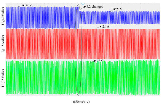
Figure 19.
Output waveform when Load 2 changed.
As can be seen from Figure 19, when Load 2 is switched at another time, Load 1’s voltage remains stable at 34 V, indicating that the switching of Load 1 has almost no effect on Load 2.
In summary, during operation, when the resistance value of one load branch is switched, the output power of the corresponding receiving circuit changes accordingly, while the output power of the other receiving circuit remains largely unaffected. This demonstrates that the load output power exhibits independence.
The experimental results have been compared with the existing literature, and the comparison results are shown in Table 3. Different coil sizes allow different misalignment distances, and the ratio of the maximum misalignment distance to the coil side length can uniformly characterize the anti-misalignment capability of the magnetic coupling mechanism. The comparative analysis indicates that while the method analyzed in Reference [21] lacks anti-rotation capability, it exhibits greater misalignment tolerance; the system discussed in Reference [22] possesses anti-rotation capability with relatively good CCRR (Coupling Coefficient under Rotation and misalignment) performance; the method proposed in this study achieves a higher CCRR value, demonstrating superior anti-misalignment performance.
Table 3.
Comparisons with existing methods.
5. Conclusions
The experimental results demonstrate effective decoupling between receivers, with cross-interference maintained at low levels, confirming the system’s capability for independent regulation of multiple loads. Load 1 achieves constant-voltage (CV) output, while Load 2 maintains constant-current (CC) output. Across a load variation range of 10–70 Ω for both loads, system efficiency exceeds 80%. These experimental results validate that the proposed dual-frequency dual-load MCR-WPT system enables the following:
- Independent power transfer and control at distinct frequencies;
- Simultaneous CV and CC output for respective loads.
Author Contributions
Conceptualization, J.M. and L.Z.; Methodology, J.M., L.Z. and Y.K.; Software, Y.C.; Validation, J.M. and L.Z.; Investigation, Y.D.; Writing—original draft, J.M.; Writing—review and editing, Y.K. and Q.Z.; Visualization, Q.Z.; Project administration, L.Z. All authors have read and agreed to the published version of the manuscript.
Funding
This research was funded by Natural Science Foundation of Chongqing (CSTB2024NSCQ-MSX0382), the Science and Technology Research Program of Chongqing Municipal Education Commission (KJQN202201103), and Graduate Innovation Project of Chongqing University of Technology (gzlcx20253146 and gzlcx20253187).
Data Availability Statement
The original contributions presented in this study are included in the article. Further inquiries can be directed to the corresponding author.
Acknowledgments
This research was supported by Yi Yang and Shiyun Xie with regard to the materials used for the experiments and theoretical analysis.
Conflicts of Interest
The authors declare no conflicts of interest.
References
- Niu, S.; Xu, H.; Sun, Z.; Shao, Z.; Jian, L. The state-of-the-arts of wireless electric vehicle charging via magnetic resonance: Principles, standards and core technologies. Renew. Sustain. Energy Rev. 2019, 114, 109302. [Google Scholar] [CrossRef]
- Basir, A.; Yoo, H. Efficient wireless power transfer system with a miniaturized quad-band implantable antenna for deep-body multitasking implants. IEEE Trans. Microw. Theory Tech. 2020, 68, 1943–1953. [Google Scholar] [CrossRef]
- Manoufali, M.; Bialkowski, K.; Mohammed, B.; Abbosh, A. Wireless power link based on inductive coupling for brain implantable medical devices. IEEE Antennas Wirel. Propag. Lett. 2017, 17, 160–163. [Google Scholar] [CrossRef]
- Lu, X.; Wang, P.; Niyato, D.; Kim, D.I.; Han, Z. Wireless charging technologies: Fundamentals, standards, and network applications. IEEE Commun. Surv. Tutor. 2015, 18, 1413–1452. [Google Scholar] [CrossRef]
- Liu, F.; Yang, Y.; Ding, Z.; Chen, X.; Kennel, R.M. A multifrequency superposition methodology to achieve high efficiency and targeted power distribution for a multiload MCR WPT system. IEEE Trans. Power Electron. 2017, 33, 9005–9016. [Google Scholar] [CrossRef]
- Ahn, D.; Mercier, P.P. Wireless power transfer with concurrent 200-kHz and 6.78-MHz operation in a single-transmitter device. IEEE Trans. Power Electron. 2015, 31, 5018–5029. [Google Scholar] [CrossRef]
- Zhang, X.; Liu, F.; Mei, T. Multifrequency phase-shifted control for multiphase multiload MCR WPT system to achieve targeted power distribution and high misalignment tolerance. IEEE Trans. Power Electron. 2020, 36, 991–1003. [Google Scholar] [CrossRef]
- Pantic, Z.; Lee, K.; Lukic, S.M. Receivers for multifrequency wireless power transfer: Design for minimum interference. IEEE J. Emerg. Sel. Top. Power Electron. 2014, 3, 234–241. [Google Scholar] [CrossRef]
- Liu, W.; Chau, K.; Lee, C.H.; Jiang, C.; Han, W.; Lam, W. Multi-frequency multi-power one-to-many wireless power transfer system. IEEE Trans. Magn. 2019, 55, 1–9. [Google Scholar] [CrossRef]
- Wu, J.; Bie, L.; Kong, W.; Gao, P.; Wang, Y. Multi-frequency multi-amplitude superposition modulation method with phase shift optimization for single inverter of wireless power transfer system. IEEE Trans. Circuits Syst. I Regul. Pap. 2021, 68, 2271–2279. [Google Scholar] [CrossRef]
- Zhang, Y.; Lu, T.; Zhao, Z.; He, F.; Chen, K.; Yuan, L. Selective wireless power transfer to multiple loads using receivers of different resonant frequencies. IEEE Trans. Power Electron. 2014, 30, 6001–6005. [Google Scholar] [CrossRef]
- Qi, C.; Huang, S.; Chen, X.; Wang, P. Multifrequency modulation to achieve an individual and continuous power distribution for simultaneous MR-WPT system with an inverter. IEEE Trans. Power Electron. 2021, 36, 12440–12455. [Google Scholar] [CrossRef]
- Qu, X.; Han, H.; Wong, S.-C.; Tse, C.K.; Chen, W. Hybrid IPT topologies with constant current or constant voltage output for battery charging applications. IEEE Trans. Power Electron. 2015, 30, 6329–6337. [Google Scholar] [CrossRef]
- Zhang, Y.; Yao, Z. A Novel TS/S-SP Variable Structure Wireless Power Transfer Converter. In Proceedings of the 2024 IEEE 10th International Power Electronics and Motion Control Conference (IPEMC2024-ECCE Asia), Chengdu, China, 17–20 May 2024; pp. 311–316. [Google Scholar]
- Hong, J.; Pan, F.; Zhang, Z.; Teng, J.; He, D. Constant current/voltage characteristics inductive power transfer system with variable static ST/FC compensation. J. Power Electron. 2024, 24, 480–491. [Google Scholar] [CrossRef]
- Tan, L.; Pan, S.; Xu, C.; Yan, C.; Liu, H.; Huang, X. Study of constant current-constant voltage output wireless charging system based on compound topologies. J. Power Electron. 2017, 17, 1109–1116. [Google Scholar]
- Pang, H.; Chau, K.; Liu, W.; Tian, X. Multi-resonating-compensation for multi-channel multi-pickup wireless power transfer. IEEE Trans. Magn. 2022, 58, 1–6. [Google Scholar] [CrossRef]
- Pang, S.; Xu, J.; Li, H.; Ma, Q.; Li, X. Dual-frequency modulation to achieve power independent regulation for dual-load underwater wireless power connector. IEEE J. Emerg. Sel. Top. Power Electron. 2022, 11, 2377–2389. [Google Scholar] [CrossRef]
- Liu, Y.; Liu, C.; Huang, R.; Song, Z. Primary multi-frequency constant-current compensation for one-to-multiple wireless power transfer. IEEE Trans. Circuits Syst. II Express Briefs 2023, 70, 2201–2205. [Google Scholar] [CrossRef]
- Xiong, W.; Jiang, F.; Liu, Z.; Zhu, Q.; Su, M. A hybrid-frequency-based multi-load wireless power transfer system with constant current or voltage outputs. IEEE J. Emerg. Sel. Top. Power Electron. 2023, 12, 1150–1160. [Google Scholar] [CrossRef]
- Budhia, M.; Boys, J.T.; Covic, G.A.; Huang, C.-Y. Development of a single-sided flux magnetic coupler for electric vehicle IPT charging systems. IEEE Trans. Ind. Electron. 2011, 60, 318–328. [Google Scholar] [CrossRef]
- Zaheer, A.; Covic, G.A.; Kacprzak, D. A bipolar pad in a 10-kHz 300-W distributed IPT system for AGV applications. IEEE Trans. Ind. Electron. 2013, 61, 3288–3301. [Google Scholar] [CrossRef]
Disclaimer/Publisher’s Note: The statements, opinions and data contained in all publications are solely those of the individual author(s) and contributor(s) and not of MDPI and/or the editor(s). MDPI and/or the editor(s) disclaim responsibility for any injury to people or property resulting from any ideas, methods, instructions or products referred to in the content. |
© 2025 by the authors. Published by MDPI on behalf of the World Electric Vehicle Association. Licensee MDPI, Basel, Switzerland. This article is an open access article distributed under the terms and conditions of the Creative Commons Attribution (CC BY) license (https://creativecommons.org/licenses/by/4.0/).