Article

A Road-Adaptive Vibration Reduction System with Fuzzy PI Control Approach for Electric Bicycles

1
Department of Information Engineering and Computer Science, Feng Chia University, Taichung 40724, Taiwan
2
Faculty of Engineering and Technology, Thai Nguyen University of Information and Communication Technology Thai Nguyen 250000, Vietnam
*
Authors to whom correspondence should be addressed.
World Electr. Veh. J. 2025, 16(5), 276; https://doi.org/10.3390/wevj16050276
Submission received: 14 July 2024 / Revised: 11 May 2025 / Accepted: 13 May 2025 / Published: 16 May 2025

Abstract

Riding comfort and safety are essential requirements for any form of transportation but particularly for electric bicycles (e-bikes), which are highly affected by varying road conditions. These factors largely depend on the effectiveness of the e-bike’s control strategy. While several studies have proposed control approaches that address comfort and safety, vibration—an influential factor in both structural integrity and rider experience—has received limited attention during the design phase. Moreover, many commercially available e-bikes provide manual assistance-level settings, leaving comfort and safety management to the rider’s experience. This study proposes a Road-Adaptive Vibration Reduction System (RAVRS) that can be deployed on an e-bike rider’s smartphone to automatically maintain riding comfort and safety using manual assistance control. A fuzzy-based control algorithm is adopted to dynamically select the appropriate assistance level, aiming to minimize vibration while maintaining velocity and acceleration within thresholds associated with comfort and safety. This study presents a vibration analysis to highlight the significance of vibration control in improving electronic reliability, reducing mechanical fatigue, and enhancing user experience. A functional prototype of the RAVRS was implemented and evaluated using real-world data collected from experimental trips. The simulation results demonstrate that the proposed system achieves effective control of speed and acceleration, with success rates of 83.97% and 99.79%, respectively, outperforming existing control strategies. In addition, the proposed RAVRS significantly enhances the riding experience by improving both comfort and safety.

1. Introduction

Due to air pollution and energy depletion issues, many countries are actively promoting energy conservation and carbon dioxide reduction in various economic sectors, especially transportation. In Taiwan, the government has set a target of selling electric-powered vehicles at a rate of 100% of the market in 2040 [1]. Among the means of transport, electric bicycles (e-bikes) have great potential to contribute to the reduction of air pollution [2]. An e-bike is a bicycle equipped with an electric motor and a battery to power the motor. There are two types of e-bikes: (1) power-on-demand e-bikes and (2) power-assisted e-bikes. In this article, the term e-bike stands for the second type, which only supports the rider while pedaling. When the rider pedals the bike, the motor controller measures the effort of the rider using the pedal torque sensor and then determines the assisted motor power according to the effort of the rider. Consequently, e-bikes have the benefits of both bicycles and electric vehicles. Riding e-bikes both improves health and reduces cyclist overload [3,4,5,6]. In addition, because they are lightweight, e-bikes have lower energy consumption costs than those of other electric vehicles. Therefore, more and more people prefer to use e-bikes in commuting and exercise activities [7,8].
Despite their advantages, e-bikes also have disadvantages. As bicycles, e-bikes are strongly affected by the environment, including wind and road conditions. These factors influence the comfort and safety when cycling. The riding comfort and safety conditions for the riders of e-bikes are defined in [9]. Riding comfort is achieved when the velocity of the e-bike is maintained around the desired value within a comfortable zone (CZ), whereas safety is achieved when the velocity of the e-bike is stable, meaning that the instantaneous acceleration of the e-bike is around zero within a safety zone (SZ). For example, the expected velocity for cycling in the urban environment is 18 km/h, corresponding to a CZ between 16 and 20 km/h. The SZ is between −0.4 and 0.4 m/ s 2 . The riding comfort and safety can be ensured by the e-bike controller with the right control strategy. In existing studies, several controller approaches were proposed to solve this problem, such as assisted power management based on a data-driven model [10], a self-tuning fuzzy logic controller (STFLC) [11], proportional–integral–derivative (PID) control [12], and fuzzy logic control [9,13]. However, these studies did not consider enough factors for riding comfort. Vibration on an e-bike also greatly affects riding comfort. This occurs due to the roughness of the road surface. On different types of road surfaces, the vibration of an electric bike is also different. Vertical vibration affects riding comfort; therefore, vertical vibration should not exceed a limit value for riding comfort [14]. In general, vehicle vibration can be reduced by the vehicle suspension system [15,16] and vehicle speed control strategies [17,18].
In addition to the control strategies mentioned above, another is the proportion-assisted power (PAP) method [19], which is also popular for off-the-shelf e-bikes. With PAP, the motor provides the proportional torque with the pedal torque of the rider. Because the PAP method does not consider riding conditions, riding comfort and safety are not guaranteed. To solve this PAP issue, e-bike manufacturers have installed multiple assistance levels for their e-bikes [20]. Each level provides a different assistance ratio. This solution allows the rider to select the level of assistance required according to the riding conditions. However, riding comfort and safety depend on the experience of selecting the level of assistance for the rider while riding. The riding comfort and safety of an e-bike can be achieved by controlling the output power of the motor to change the speed and acceleration of the e-bike when riding. However, the vibration generated by the external road environment will also affect riding comfort and safety. Most e-bike motor control strategies do not consider the vibration caused by the road environment. Therefore, the comfort and safety of e-bike riding are highly dependent on the rider’s experience in dealing with road conditions. The purpose of this study is to construct a system that can automatically select the assistance level to improve the comfort and safety of riders when riding e-bikes. In this study, we considered the impact of vibrations generated by the road environment on the e-bike riding experience. The vibration factor information when riding an e-bike is collected as the input parameter for the control strategy formulation, so as to control the speed and acceleration of the e-bike.
While vibrations may not be the single most important factor in e-bike design compared with aspects such as battery range, motor efficiency, or braking safety, they represent a critical engineering concern that directly affects multiple key dimensions of e-bike performance, including the following:
  • Structural integrity: Excessive vibrations contribute to material fatigue, especially in welded joints and electronic mounting points, which can shorten the lifespan of the frame and internal components.
  • Electronic reliability: Vibrations can negatively impact sensitive components such as batteries, controllers, and PCBs (printed circuit boards), increasing the risk of failure under repeated mechanical stress.
  • User comfort and safety: Vibrations degrade ride comfort and may reduce control stability, especially at higher speeds or on uneven terrain, which can compromise rider safety.
  • Energy efficiency: Vibrations introduce mechanical inefficiencies in the drivetrain and rolling resistance, which, in turn, affect power consumption and reduce the effective range.
In light of these factors, our vibration analysis was conducted to evaluate and reduce the dynamic response of an e-bike during real-world operation. This contributes to a more reliable, comfortable, and durable vehicle, aligning with current engineering best practices in e-bike product development. To effectively suppress vibrations during e-bike operation under varying road conditions, a fuzzy PI control strategy is adopted in this study. The use of fuzzy logic enables the controller to handle system uncertainties and nonlinearities without requiring an exact mathematical model. This is particularly suitable for e-bike applications, where factors such as terrain roughness, rider behavior, and dynamic loading vary unpredictably. By integrating fuzzy inference with a conventional PI structure, the proposed controller benefits from both adaptive decision making and steady-state accuracy. The proportional–integral (PI) component ensures that the system maintains stability and minimizes long-term error, while the fuzzy logic layer dynamically adjusts control actions based on real-time conditions and expert-defined rules. This hybrid approach enhances vibration attenuation performance and rider comfort across a wide range of operating scenarios.
In this study, we propose a Road-Adaptive Vibration Reduction System (RAVRS) for multiple levels of assistance provided by e-bikes. The RAVRS is a high-level control system aimed at transforming a manual pedal-assisted level selection e-bike into an automatic one using a smartphone. The RAVRS is designed to be used with the smartphones of cyclists mounted on the handlebars. The strategy of assistance-level selection is performed using a fuzzy logic-based road-aware vibration adaptation policy. The RAVRS automatically selects the assistance level to regulate the speed, acceleration, and vibration of the e-bike in a comfortable and safe zone. When the road is not flat or there are potholes or bumps, the vibration of the e-bike will increase. This context is sensed by the accelerometer inside the smartphone. In this scenario, the level of assistance is reduced in order to decrease the speed of the e-bike, which adjusts the vibration of the electric bike. When the road surface is good, the assistance levels are selected to ensure that the e-bike speed is around an expected value with safe acceleration. Furthermore, a Matlab/Simulink (Verson R2020a, The MathWorks, Inc., Natick, MA, USA)-based simulation and an Android-based prototype were implemented to verify the feasibility and superiority of our system. In particular, the simulation and experimental results show that our system can significantly improve riding comfort and safety. The remainder of this article is organized as follows. Section 2 discusses related work on e-bike control strategies. Section 3 defines the problem of our vibration reduction system for e-bikes and presents our approach to solving this problem. Section 4 demonstrates the implementation of the system prototype. The simulation and experimental results are discussed in Section 5. Finally, Section 6 concludes the study.

2. Related Work

Many control systems have been proposed for e-bikes, to improve the experience of cycling. Considering the health of riders, several studies have proposed controllers to maintain the rider’s heart rate (HR) within an expected zone [21,22,23,24]. In [21], a switch controller manages power sharing between the battery and human body to improve the rider’s metabolism and manage the battery’s state of charge (SOC). The main idea is to optimize this power-switch element to change states to achieve a balance between lack of fatigue and keeping the SOC high. This study examines these parameters to calculate calorie burn. When the electric mode is activated, the SOC level drops. When the human power mode is activated, the human power source provides energy. The model converts the bike speed into the rider’s heart rate, which is then converted into calories burned based on some equations. The power-switch element is activated or deactivated adaptively depending on the heart rate. The authors of [22] describe the development of an electronic system that transforms an electric-assisted bicycle into a smart health monitoring system, enabling people with limited physical abilities or health problems to gradually initiate physical activity following a medical regimen (e.g., maximum heart rate, power output, training time). The system was developed to monitor the rider’s fitness, instantly analyze the data, and provide electrical assistance to reduce muscle strain. Additionally, the system can recover the same physiological data used by medical centers and program it into e-bikes to track patients’ health. The authors of [23] present a system concept that utilizes closed-loop heart rate control on an electric bicycle to enable cardiovascular patients to train outdoors safely and comfortably. To this end, a control loop was developed and implemented on a prototype bicycle using a mid-drive motor and an Arduino microcontroller to receive the current heart rate and adjust the motor power accordingly. With this prototype, the controller parameters of PI and PID controllers can be determined heuristically using a test object. In [24], the authors propose a novel energy management system for HEVs (hybrid electric vehicles) that regulates the rider’s heart rate using an optimal control approach and manages motor assistance by incorporating trip information. The system consists of a control phase and a planning phase. In the control phase, a model predictive controller regulates the heart rate by varying the motor power and gear ratio to maintain a user-defined effort level while taking constraints into account. The planning stage processes prior information about the user and the route to estimate the power demand in different segments of the trip and calculate the optimal motor power for each segment. Each section’s motor power limit is then established to limit energy consumption and save energy for the sections that need motor power the most. The authors of [24] propose an HR regulation controller using an optimal control approach. A planning module divides the route into segments and determines the energy consumption limit for each segment based on the road profile. The controller adjusts the motor power and transmission gear ratio to keep the HR in an expected zone while adhering to the constraints provided by the planning module.
Considering the effect of pollution on rider health, Sweeney et al. [25] designed a cyber–physical control system to indirectly control rider ventilation rates to mitigate the pollution effect. The ventilation rate controller was developed on a smartphone and can manage the interaction between the rider and the motor through Bluetooth. By adjusting the motor power, the air volume that the rider inhales per minute can be regulated. Considering the use of an e-bike as a mobile exercise machine, the authors of [26] designed and implemented a smartphone application (app) to manage the physical activity levels of the rider while riding an e-bike. The smartphone can send commands to the e-bike through Bluetooth to change the assistance levels. Depending on the route selected by the rider before riding, the route is divided into segments. The power required for each segment is then calculated according to the profile of the road, the e-bike, and the rider. Based on the total power required and the power of the rider planned for training, the level of assistance for each segment is assigned.
Considering energy-efficient solutions, Tal et al. [27] propose a speed advisory system for electric bicycles (SAECy) based on vehicular communications. The purpose of the SAECy is to guide the rider to an optimal e-bike speed in order not to stop at an intersection due to a red light when the e-bike approaches the intersection. The SAECy can be installed on a smartphone. When the e-bike approaches an intersection, the SAECy receives and considers messages from the traffic light controller via vehicular communication. The input data of the SAECy includes traffic light timing, traffic light location, and wind information. Based on these inputs, the SAECy uses a fuzzy-based algorithm to calculate the optimal speed adapted to the traffic signal and wind speed. The mentioned works addressed various control targets; however, they did not evaluate riding comfort and safety.
Several works have proposed systems to address both the comfort and safety of riders [9,10,11,12,13]. The authors of [9] introduce an electric-assisted bicycle equipped with a power management system using fuzzy control technology. A system that uses instantaneous pedal frequency, road slope, and riding speed as fuzzy input variables is established. The motor assistance power is dynamically adjusted according to instantaneous parameters such as riding speed, cadence, road slope, etc. A Mamdani-based fuzzy logic controller is used to regulate the output of the lithium battery to improve safety and comfort during riding while minimizing the rider’s muscle fatigue. In [10], a data-driven model predictive control (MPC) approach is used to study electric bicycles to develop road disturbance estimations and formulate a new control algorithm scheme for electric bicycles with uncertain road conditions in urban traffic. The developed model is proposed for model predictive driving options of electric bicycles to provide optimal motor torque operation for predicted road disturbances. The driving profile is designed to simulate urban driving on different road types by taking pedal usage frequency and pedal load measurements in combined driving into account. The proposed control model provides an innovative approach for the design of optimal longitudinal vehicle control systems for electric microvehicles while considering a data-driven MPC approach. J.S. Lee et al. [11] proposed an improved FLC called STFLC, which was designed specifically for power-assisted electric bicycles. In addition to the typical FLC, the proposed scheme also adds a rule adjustment module to dynamically adjust the rule base during the fuzzy reasoning process. STFLC does not require an additional slope sensor to perceive the road conditions, and the number of fuzzy rules remains unchanged with the newly added rule adjustment module.
In [12], Abagnale et al. propose a velocity controller while considering the comfort of the ride. The controller consists of feed-forward and feedback control modules that calculate the motor torque required to maintain the expected velocity. The feed-forward control module generates one part of the control signal using a mathematical e-bike model with the expected speed. The feedback control module uses the PID method to generate another part of the required torque based on the velocity tracking error. O. Uyar et al. [13] designed and implemented a fuzzy logic-based control approach to provide comfort and safety in electric-assisted bicycles. The authors of [13] proposed an enhanced fuzzy logic control strategy that takes the interaction between people and vehicles into account and used a hash table method to operate the fuzzy logic rule base. A new type of electric bicycle transmission mechanism and intelligent control system was designed. A load cell-based mini-sensor system was developed to measure the pedal torque. The transfer function of the system was obtained through data-based system identification, and the control algorithm was tested on this model and transferred to a real environment. A moving-average filter was applied to reduce the effect of the error. The fuzzy control algorithms were embedded into the microcontroller’s memory according to the hash table method, without using a search algorithm to enable the fuzzy controller outputs; as a result, the cycle time and computational burden were reduced.

3. Proposed Road-Adaptive Vibration Reduction System

This section presents the proposed RAVRS. First, the road-adaptive vibration reduction problem is defined in Section 3.1. Then, Section 3.2 introduces the proposed RAVRS architecture used to solve the problem. Finally, Section 3.3 and Section 3.4 describe the control object, that is, PAP-based e-bikes, using a dynamic model.

3.1. System Overview

An overview of the proposed RAVRS is shown in Figure 1. The e-bike controller is applied using the PAP method and provides different levels of assistance to the rider to select while cycling. A gateway is installed on the e-bike to interface the smartphone of the rider with the e-bike through Bluetooth. The gateway forwards speed data received from the e-bike to the smartphone and forwards the assistance-level selection command received from the smartphone to the e-bike in a real-time manner. In addition, the smartphone is mounted on the e-bike to continuously monitor the vibration of the e-bike through its built-in accelerometer. Based on the current riding conditions, the RAVRS app installed on the smartphone, using our proposed fuzzy logic-based method, controls the speed of the e-bike by adjusting the assistance levels to guarantee the vibration, speed, and acceleration of the e-bike within the zone of comfort and safety of riding. In particular, when the vibration of the e-bike exceeds the limit (due to road potholes or bumps), the assistance level is reduced to decrease the speed of the e-bike and thus maintain the vibration of the e-bike within the limit zone. Otherwise, the assistance level is selected to maintain both the e-bike speed within the CZ around the expected value given by the rider and the e-bike acceleration within the SZ.

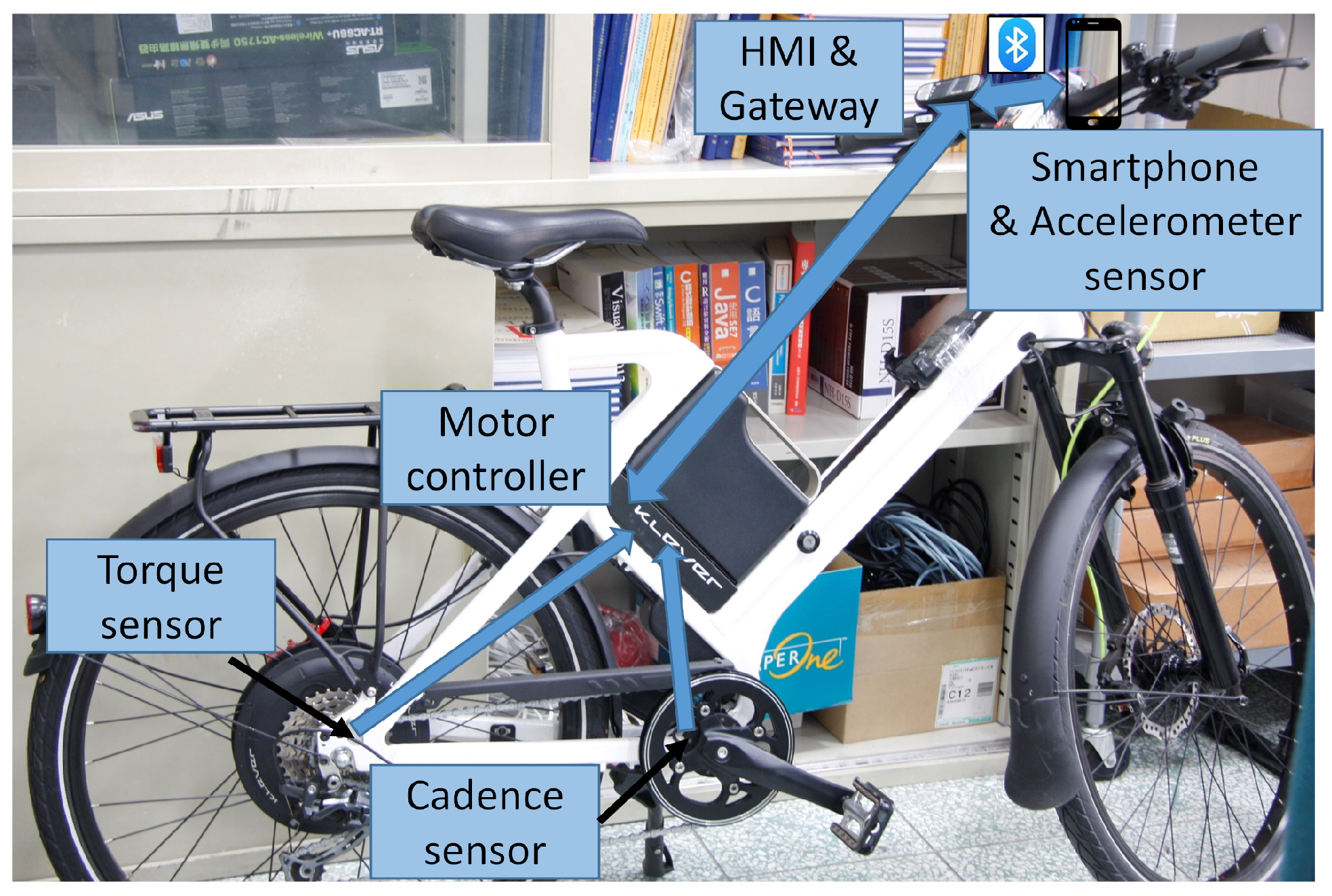
3.2. System Architecture of the RAVRS

The architecture of the proposed RAVRS for e-bikes is shown in Figure 2. The main part of the proposed system is the RAVRS app installed on the smartphone. The fuzzy proportional–integral (PI) control mechanism proposed in the app is responsible for controlling the velocity of the e-bike ν around the given expected value ν * when the vibration of the bike V does not exceed the given limited value V m a x , or maintains the velocity ν at a proper value that is lower than the expected ν * to maintain vibration a z v i b within a comfortable range. The control mechanism processes input parameters consisting of the velocity error e, acceleration a, and vibration deviation d to request the appropriate level of assistance L of the e-bike through the gateway to ensure the objective of the system. After that, the power-assisted controller inside the e-bike commands the motor to provide assistance power based on the assistance level L and the human pedal torque T p . Motor and human power propel the e-bike to new state variables. In short, the RAVRS continuously maintains the quality of riding by adapting the assistance levels of the e-bike to changes in the riding conditions.

3.3. E-Bike Dynamic Model

The longitudinal dynamics of an e-bike are the relationship of velocity with the motor torque T m and pedal torque of the cyclist T p and the resisting forces F r e s , as described in the following [28]:
v ˙ = ( T p + T m ) k F r e s r w m r w
where m is the sum of the e-bike mass m 1 and rider mass m 2 ( m = m 1 + m 2 ), r w is the radius of the rear wheel, and k is the ratio between the middle gear r m g and rear gear r r g ( k = r r g / r m g ).
F r e s , consisting of three resistance forces from rolling friction, air, and slope, can be calculated as follows:
F r e s = F f r i c + F a i r + F s l o p e
with
F f r i c = μ m g cos α
where μ , g, and α are the rolling friction coefficient, the gravitational acceleration, and the slope angle, respectively.
F a i r = 1 2 C d A c ρ v 2
where C d is the atmospheric drag coefficient, A c is the vehicle frontal area, and ρ is the air density.
F s l o p e = m g sin α

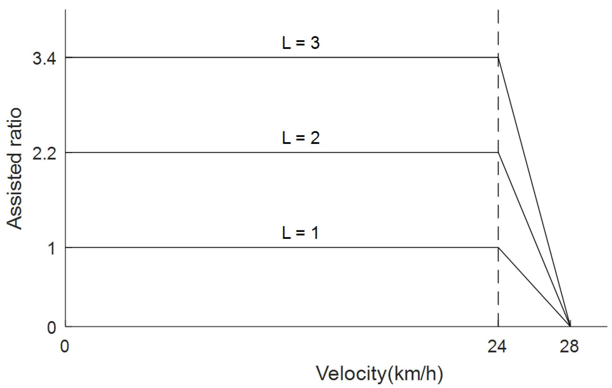
3.4. PAP Method for E-Bikes

A pedal-assisted e-bike has N assistance levels. At assistance level L ( 0 L N 1 ), the motor assists a torque T m proportional to T p , as described in the following [29]:
T m = S L ( v ) T p
where S L ( v ) is the assistance ratio of the motor torque compared with the human torque. S L ( v ) depends on the selected assistance level L and the instant velocity v of the e-bike, as described in the following function:
S L ( v ) = S L m a x if 0 < v v v m a x v v m a x v if v < v < v m a x 0 if v v m a x
Although the e-bike velocity v does not exceed a predefined value v , S L is S L m a x , the maximum assistance ratio of the level L; otherwise, S L gradually decreases and reaches 0 as soon as v is larger than v m a x . According to the laws of most countries, v m a x is 25 km/h. For example, the e-bike used in this work has v = 24 km/h, v m a x = 28 km/h, N = 4, v 0 m a x = 0%, v 1 m a x = 100%, S 2 m a x = 220%, and S 3 m a x = 340%; a function graph of S L ( v ) is shown in Figure 3.
The output of the motor assistance torque T m is calculated at the preset assistance level L according to the input information of the e-bike speed v by using Equation (7) to calculate the function value S L ( v ) ; this is then obtained using Equation (6). For example, if the e-bike rider selects L = 2 , then when the e-bike speed v is between 0 and a predefined value v , the motor assistance torque T m is the product of the function value S L ( v ) and the rider’s pedal torque T p . The assistance level L is selected by the e-bike rider based on their road-riding experience. Since there are no substantive reference criteria for the selection of the assistance level L, this does not help the rider’s comfort and safety when riding an e-bike. In this study, we propose a fuzzy PI with the velocity error, acceleration, and vibration deviation as input parameters to assist e-bike riders in automatically selecting the assistance level L. This means that when riding an e-bike, the rider does not need to rely on their own road-riding experience to select the assistance level L; thereby, this improves the comfort and safety of riders riding e-bikes.

4. Fuzzy PI Control Mechanism of the RAVRS

This section presents the fuzzy PI control mechanism proposed for the RAVRS. The fuzzy PI controller proposed in this study for the RAVRS uses three input parameters, namely, the velocity error, acceleration, and vibration deviation, unlike PID and fuzzy1, which use only one input parameter of velocity error. This makes the RAVRS perform better in the application proposed in this study. First, the control structure is introduced in Section 4.1. Then, the modules of the mechanism are formulated in Section 4.2 and Section 4.3.

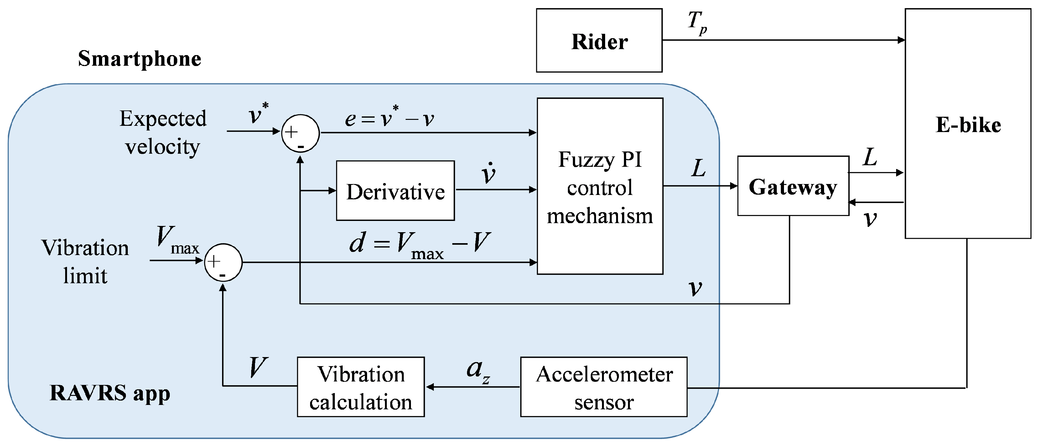
4.1. Control Structure
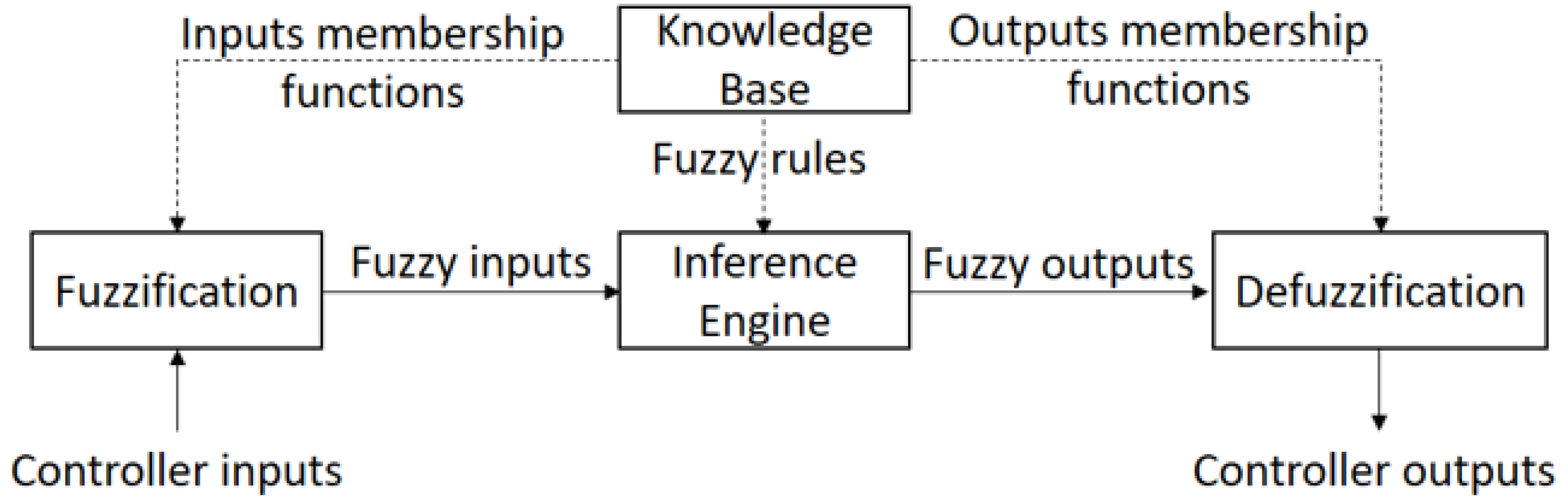
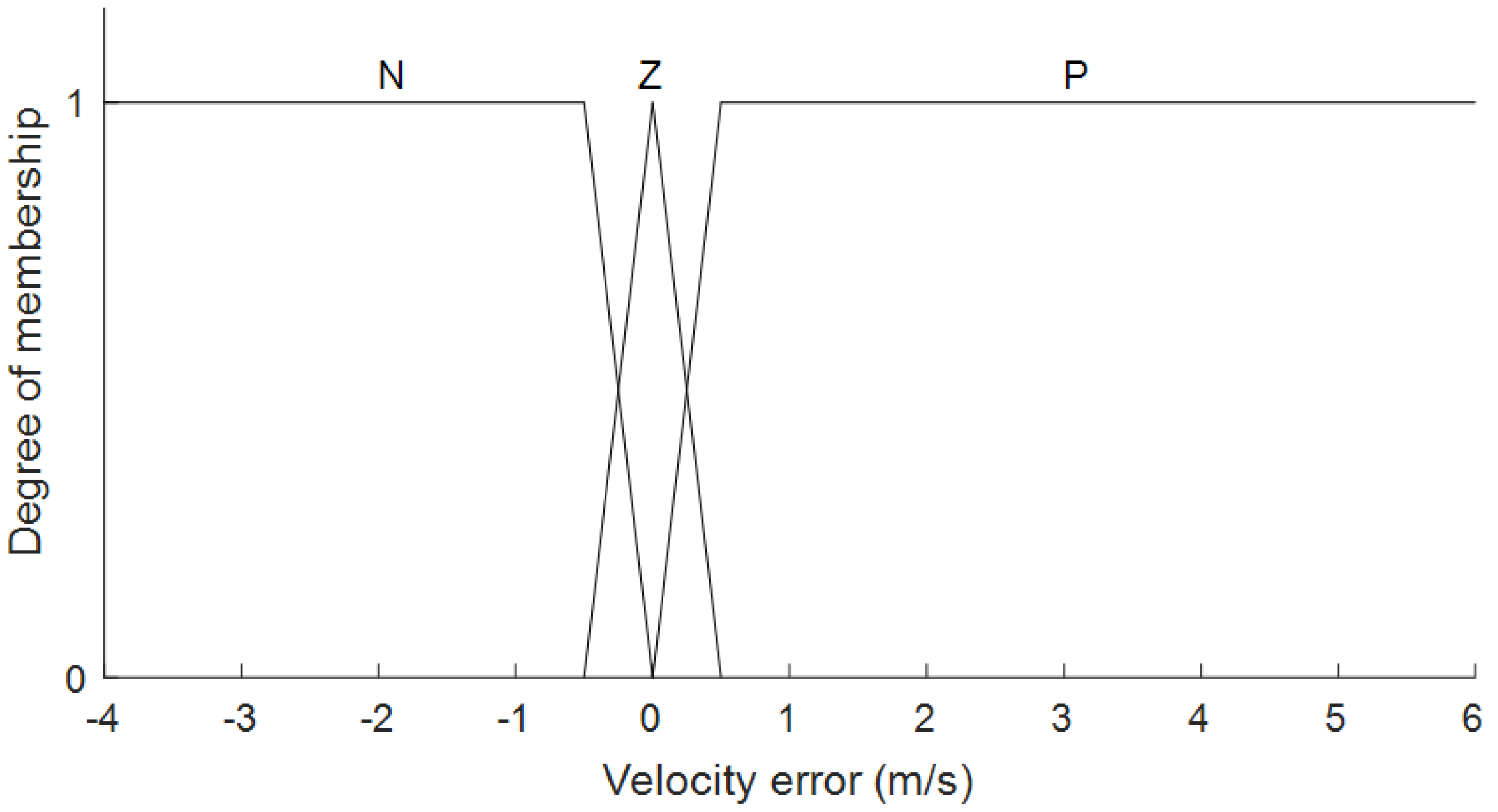
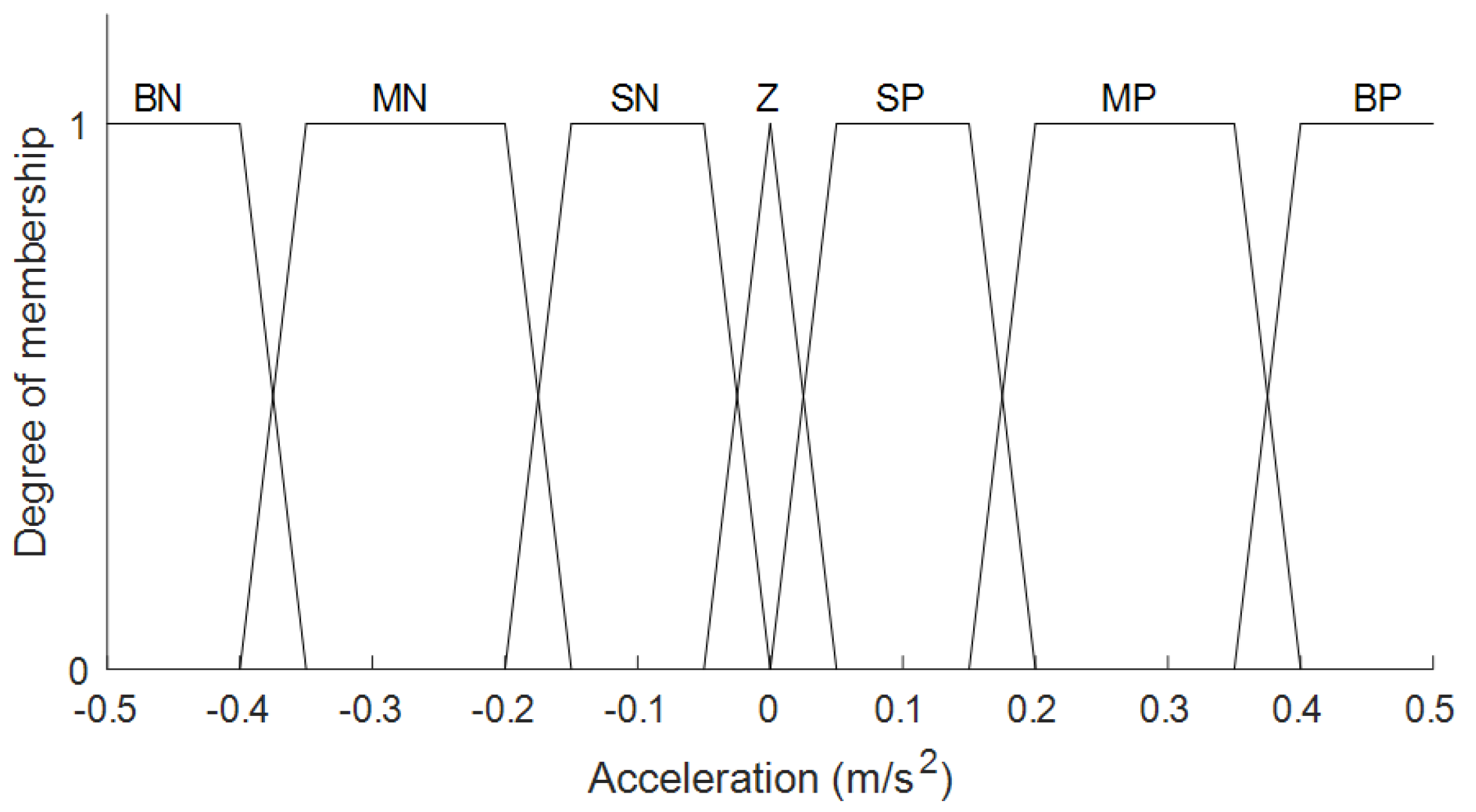
Figure 4 shows an overview of the proposed fuzzy PI control mechanism, which consists of a traditional fuzzy control method and an integrator. As described above, the inputs of the proposed mechanism are the velocity error e, acceleration a = v ˙ , and vibration deviation d. The output is the assistance level L used to change the current assistance level of the e-bike. To perform its role, the fuzzy control method first produces the change-of-control output Δ L , and then the integrator integrates Δ L over time to obtain a new control output L.
A fuzzy control architecture comprises a knowledge base, fuzzification interface, inference engine, and defuzzification interface units [30], as shown in Figure 5. The knowledge base contains all knowledge of the controller, including fuzzy control rules and membership functions. The inference engine performs an inference procedure based on the fuzzy control rules and given fuzzy inputs to produce fuzzy outputs. The fuzzification and defuzzification components provide interfaces for the inference engine. Using the membership functions, the fuzzification interface converts the actual controller inputs into fuzzy inputs, and the defuzzification interface converts the fuzzy outputs into the real controller outputs.

4.2. Fuzzification

In our fuzzy logic-based assistance-level-changing mechanism, the control input variables are fuzzified into different linguistic terms (i.e., fuzzy sets). Assuming that A is a fuzzy set, x is a crisp value, and the membership function μ A ( x ) converts x into a fuzzy value that shows the degree of truth of x belonging to a member of A, the defined domain of A is the following [30]:
A = { ( x , μ A ( x ) ) | b x c }
For the velocity error variable e, the fuzzy sets defined with the membership functions are shown in Figure 6 [31,32]. Because the limitation of the e-bike velocity in many countries is 6.94 m/s (25 km/h), the desired velocity set by the rider may vary from 3 to 6 (10.8 to 21.6 km/h), and the CZ is defined as the area of velocity with error ± 0.5 m/s compared with the expected velocity. Therefore, fuzzy sets of velocity error variables are defined as negative N e ( e < 0 m/s), zero Z e ( 0.5 e 0.5 m/s), and positive P e ( e > 0 m/s). The velocity error range is from −4 to 6 m/s.
For the acceleration variable a = v ˙ , the fuzzy sets defined with the membership functions are shown in Figure 7. The safe acceleration zone (SZ) ranges from −0.4 to 0.4 m/s s 2 [31]. Therefore, the fuzzy sets of the acceleration variable are defined as big negative B N a ( a < −0.35 m/ s 2 ), medium negative M N a ( 0.4 a −0.15 m/ s 2 ), small negative S N a ( 0.2 a 0 m/ s 2 ), zero Z a (−0.05 a 0.05 m/ s 2 ), small positive S P a ( 0 a 0.2 m/ s 2 ), medium positive M P a ( 0.2 a 0.4 m/ s 2 ), and big positive B P a ( a > 0.35 m/ s 2 ).
For the vibration deviation variable d, the fuzzy sets defined with the membership functions are shown in Figure 8. The limitation of vibration for riding comfort is set by the rider. The fuzzy sets of d are defined as negative N d ( d < 0 m/ s 2 ), zero Z d (−0.05 d 0.05 m/ s 2 ), and positive P d ( d > 0 m/ s 2 ).

4.3. Inference Rules and Defuzzification

The fuzzy rules for the Sugeno inference engine are established in Table 1 and Table 2. Table 1 shows the relationship between the vibration deviation variable d and the fuzzy output variable. When d is positive, P d , the fuzzy output is the output of the inference engine with the rules provided in Table 2.
First, the AND operator computes the product of fuzzified input values to weight every output of the rule. Then, the crisp output calculated by the defuzzification phase is the weighted average of all rule outputs, as shown in the following:
Δ L = μ N d ( d ) ( 1 ) + μ Z d ( d ) 0 + μ p d ( d ) k μ N d ( d ) + μ Z d ( d ) + μ p d ( d )
where k is the output of the inference engine with the rules provided in Table 2.
k = i = 1 7 j = 1 3 ( μ i a ( a ) μ j e ( e ) R i j ) i = 1 7 j = 1 3 ( μ i a ( a ) μ j e ( v e ) )
k = i = 1 7 j = 1 3 ( μ i a ( a ) μ j e ( e ) R i j ) i = 1 7 μ i a ( a ) j = 1 3 μ j e ( v e )
where μ i a ( a ) and μ j e ( e ) , with i = 1, 2, …, 7 and j = 1, 2, 3, are the membership functions of fuzzy sets of the acceleration variable a and velocity error variable e, respectively. For example, μ i a ( a ) stands for μ B N a ( a ) , which is the membership function of the fuzzy set B N a . R is the fuzzy rule matrix extracted from Table 2.
In our design,
μ N d ( d ) + μ Z d ( d ) + μ p d ( d ) = 1
i = 1 7 μ i a ( a ) = 1
j = 1 3 μ j e ( e ) = 1
Therefore,
Δ L = μ N d ( d ) + μ p d ( d ) i = 1 7 j = 1 3 ( μ i a ( a ) μ j e ( e ) R i j )
The output of the traditional fuzzy control method is integrated over time by the integrator. The assignment I t is the output of the integrator at time t. Thus,
I t = i = 0 t ( Δ L i Δ t ) = I t 1 + Δ L i Δ t = N I t > N 0 I t < 0 I t 0 I t N
Finally, the assistance level selected L is around I t .
L = R o u n d ( I t )

4.4. RAVRS Application Implementation

We implemented the RAVRS app using an Android Studio IDE (integrated development environment). The RAVRS app prototype includes main and setting interfaces, as shown in Figure 9. The main interface, based on our developed energy monitoring system for e-bikes [33], shows energy-related information of the e-bikes and the rider, including the remaining battery capacity, distance traveled by the bike, speed, assistance level, pedal torque, etc. Through the setting interface, the rider can set the reference values for the fuzzy PI controller, including the expected velocity v * and the limitation of vibration V m a x . In the interface, the rider can also switch on/off the adaptive vibration reduction function of the system. If this function is turned off, the e-bike works as normal and the rider can manually select assistance levels through the HMI (human–machine interface).
The vibration is detected by the accelerometer of the cyclist’s smartphone. The sensor measures the acceleration on the three axes a x , a y , and a z [34]. For vibration sensing, vertical projection acceleration is used. The smartphone is mounted on the handlebar in the horizontal axis with respect to the road. Therefore, a z is used to compute the vibration. In related work, vibration is calculated using the weighted root mean square (w-RMS) of a z [35,36,37,38]. For simplicity, the RMS of a z is used to evaluate the vibration in our work, and vibrations are characterized as acceleration (m/ s 2 ). The vibration can be given as follows:
V = R M S ( a z ) = 1 n 1 n a z i 2
where n is the number of samples within a controller cycle time.
In Table 3, the relevant parameters of the fuzzy PI controller are set according to [31,32]. The default value of v * is 18 km/h; therefore, the CZ is in the range of 16 to 20 km/h. V m a x has a default value of 1.2 m/ s 2 , as per our experience. The maximum output of the assistance-level variable of the fuzzy PI controller is L = 3 because the experimental e-bike that we use provides N = 4 assistance levels. The controller works on a cycle time of 1 s. The vibration V is calculated using Equation (18), which is the RMS of 50 vertical acceleration samples within the previous control cycle.

5. Experimental Results

This section presents the experimental setup and the results of the simulation of the system using the variables of real input data collected from experimental riding to demonstrate the performance of the RAVRS. The experimental setup is described in Section 5.1. The dynamic e-bike model is first validated in Section 5.2. The quality of driving and maintaining performance is then evaluated in two different scenarios, which are a high-class road (the vibration does not exceed the limitation value) (Section 5.3 and Section 5.4) and a rough road (Section 5.5), to prove the quality of our proposed approach.

5.1. Experimental Setup

We model and simulate the RAVRS in Matlab/Simulink with inputs of real data collected from the implemented system. The parameters for the e-bike model and fuzzy PI controller are given in Table 3 and Table 4, respectively. In relation to the dynamic model of the e-bike, the environmental conditions for the simulations are shown in Table 5. The parameter settings are taken from [31,32]. The rider mass set in the simulations is 60 kg. The vibration model is constructed using the relationship between the vibration and speed measured from real-world experiments.
The human torque and road slope profiles were extracted from an experimental trip. During the trip, we collected the human torque, speed of the e-bike, assistance levels, and altitude. The altitude was provided by the built-in GPS (Global Positioning System) of the smartphone and was collected to understand the road geography. Due to the error in altitude measured by the GPS, the altitude is not used to generate the slope profile of the road. Instead, the slope profile is given using the dynamic e-bike model while knowing the air density of the human torque, the electric bike speed, the friction force, and the air force. Figure 10 presents the collected data as a time series, and Figure 11 presents the profiles of the human torque and road slope along with the riding distance. As observed, geographically, the road trip is likely to have gone up a hill. On the road, there are some local uphill and downhill sections. When riding on the flat road segment, the rider torque is normal; when going up the hill, the human torque is higher, and the e-bike speed may decrease; however, when going down the hill, the e-bike speed is higher even when the rider does not press the pedal.
The comfort index (CI) and the safety index (SI) are used to evaluate the performance of riding comfort and safety for the RAVRS. The CI is the ratio between the number of velocity samples within the CZ and the total number of velocity samples during the experiment. Similarly, the SI is the ratio between the number of acceleration samples whose values are inside the SZ and the total number of acceleration samples during the experiment. The higher the index, the better the performance the control strategy provides.
To evaluate the proposed RAVRS’s performance, we conduct two simulations. The first simulation is to evaluate the quality of the riding considering only the velocity and acceleration control performance (vibration is ignored). Two stages of the experimental trip are examined, consisting of a starting stage and an after-starting stage. Different control strategies are used, including manual, PID [39], and other fuzzy methods, for comparison with the proposed method. The input of PID is the velocity error. In our experiments, the gain parameters of the PID controller are chosen as K P = 1 , K I = 4 , and K D = 5 . The other fuzzy controller is designed with only one input parameter, which is the velocity error (namely fuzzy1). The second simulation aims to evaluate the performance of vibration reduction. In this simulation, we assume that there is a rough road segment on the road trip that causes the vibration of the e-bike to be higher than the limitation.

5.2. E-Bike Model Validation

To validate the dynamic model of our e-bike, we conducted four trips, each of which only used one assistance level that the e-bike supported, i.e., from zero to three, for our experimental e-bike, respectively, from the first trip to the fourth trip. The data collected included the human torque and e-bike speed. After being collected, the data were fed to the e-bike dynamic simulation system, assuming that the slope was zero, to validate the e-bike model. The data collected and the results of the dynamic simulation of the e-bike are shown in Figure 12. The figure shows that the output of the e-bike speed from the simulation e-bike is similar to the actual e-bike speed overall. There are differences between the simulation and the real speed due to the existence of a road slope.
This experiment was conducted by performing four riding trials at different e-bike assistance levels (L), during which the real riding speed (real speed) of the e-bike, the pedal torque ( T p ), and the motor assistance torque ( T m ) were recorded. Based on the recorded pedal torque ( T p ) and motor assistance torque ( T m ) values for each trial, the simulated riding speed (sim speed) for each experimental ride was calculated. Figure 12 presents the variations in real riding speed (real speed) and simulated riding speed (sim speed) across the four experimental rides at different e-bike assistance levels (L), with the slope set to 0.

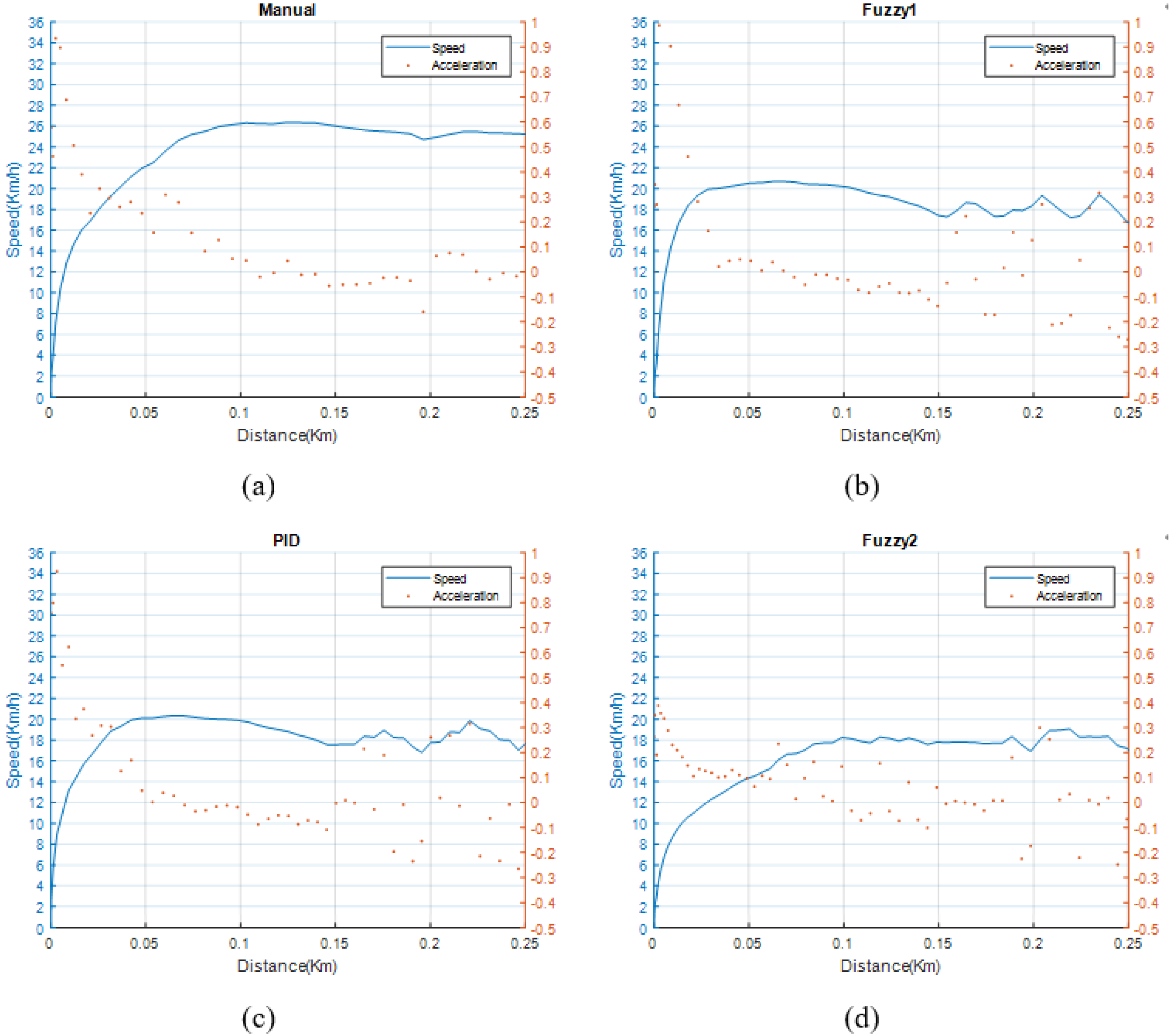
5.3. Quality of Riding at the Starting Stage

This section presents the results of the first simulation described in Section 5.1, focusing on the starting stage. The starting stage is the period from the time that the e-bike is started to the time that the e-bike velocity falls inside the CZ. The performance in this stage is evaluated according to the stage length and SI. Figure 13 shows the simulation results with different control approaches for the starting stage. In the experimental trip that uses manual mode, the speed of the e-bike increases and reaches 25 km/h at a distance of 0.1 km. With the fuzzy1 and PID approaches, the e-bike speed overshoots to 20 km/h and then falls inside the CZ from a distance of 0.1 km. With our method, the speed of the e-bike is reached in the CZ at a distance of 0.065 km without overshooting. In general, the acceleration increases very quickly at the beginning and then gradually decreases to the SZ. The higher the acceleration, the more dangerous the situation of the rider may be. The acceleration for the manual, fuzzy1, PID, and proposed methods reaches maximum values of 0.95 m/ s 2 , 1.0 m/ s 2 , 0.95 m/ s 2 , and 0.4 m/ s 2 , respectively. It is clear that our proposed method performs better than others in the initial stage. Our method can ensure that the starting acceleration is safer than others because both velocity and acceleration are monitored and controlled in the proposed system. However, fuzzy1 does not consider acceleration. The PID, despite considering acceleration, is a linear controller, for which the gain parameters are not changed with all e-bike states. Table 6 compares the performance of the control approaches.

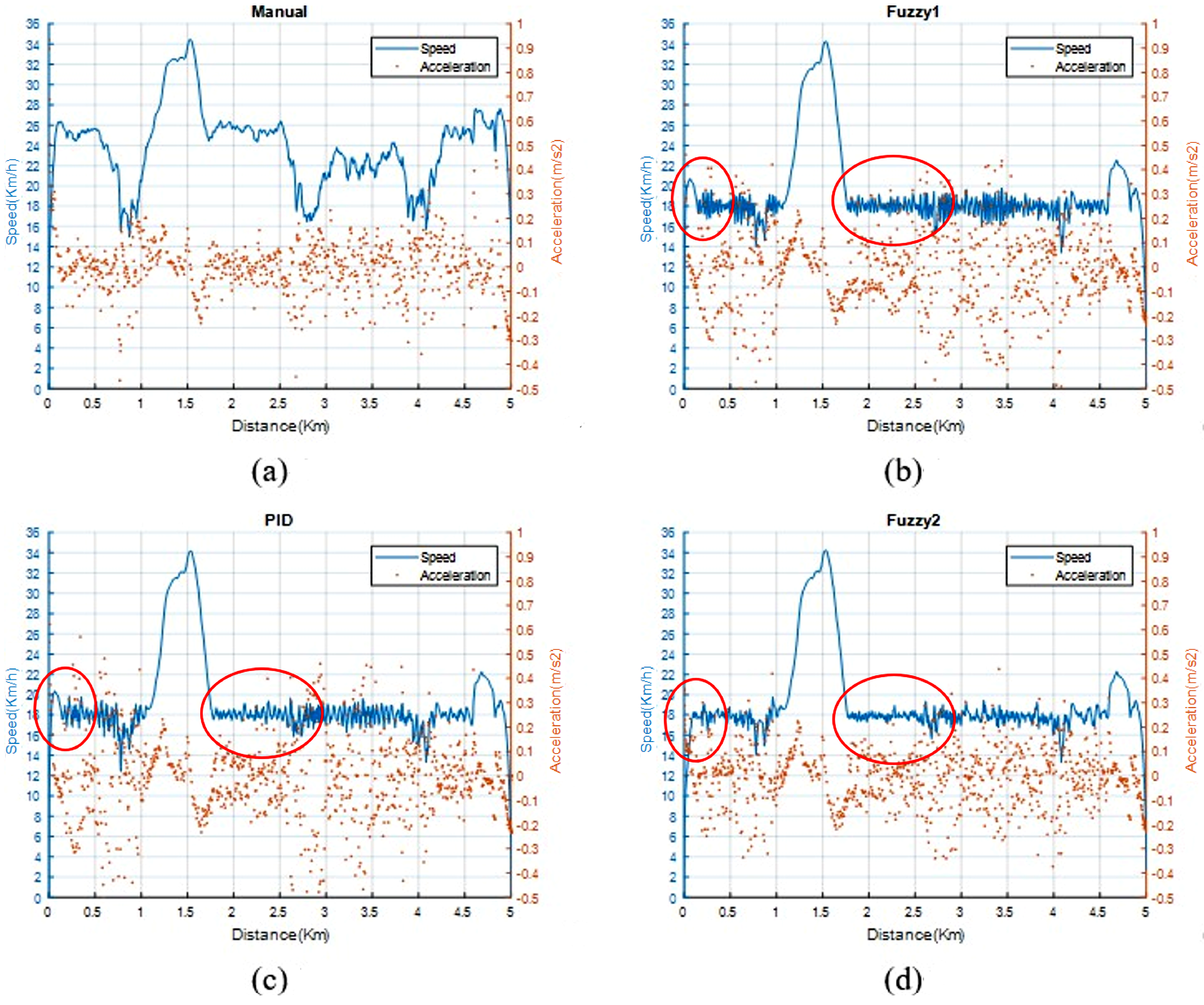
5.4. Velocity and Acceleration Control Performance

This section presents the results of the first simulation described in Section 5.1, focusing on the stage after starting. Table 6 summarizes the comparison results for the post-start stage, presenting the ratios of samples where each control strategy maintained speed and acceleration within the CZ and SZ intervals, respectively, relative to the total number of speed and acceleration samples collected during the experiment. The proposed method achieved control ratios of 83.97% for speed and 99.79% for acceleration, surpassing the performance of the comparison strategies, namely, fuzzy1 (82.13% and 98.01%) and PID (80.67% and 95.30%). These results indicate that the proposed method provides more effective speed and acceleration regulation, which may contribute to enhanced riding comfort and safety. Figure 14 presents the experimental results for the post-start stage, illustrating the variations in speed and acceleration among the evaluated methods. In the manual method, the e-bike speed fluctuates considerably and is highly influenced by the road slope. In contrast, the automatic control methods maintain velocity more effectively; however, certain segments still fall outside the control zone (CZ). Specifically, in downhill segments, the assistance level drops to zero, yet the speed does not decrease accordingly since the minimum assistance level does not support negative torque. Conversely, in uphill segments, the speed occasionally falls below the desired level due to insufficient human torque under these challenging riding conditions.
Compared with the other methods, the proposed control strategy exhibits significantly reduced fluctuations in speed, resulting in smoother performance. This advantage is particularly notable between 1.5 km and 3 km on the distance axis, where the speed profile demonstrates substantially less vibration. Furthermore, during the initial acceleration phase (0 km to 0.5 km), the proposed method effectively suppresses momentary speed peaks, thereby providing more precise velocity control and improving rider comfort. In terms of acceleration, the proposed method also demonstrates superior performance. As observed in Figure 14, the distribution of acceleration values is more concentrated than those of the other methods, indicating a lower degree of dispersion. This suggests that the proposed control strategy enables quicker response times and maintains the e-bike’s velocity closer to the target speed, contributing to a more stable and comfortable riding experience. The quantitative results are summarized in Table 6. The proposed method achieves control ratios of 83.97% for speed and 99.79% for acceleration, outperforming the comparison methods fuzzy1 (82.13% and 98.01%) and PID (80.67% and 95.30%). These findings further confirm the effectiveness of the proposed method in enhancing both control precision and rider comfort.

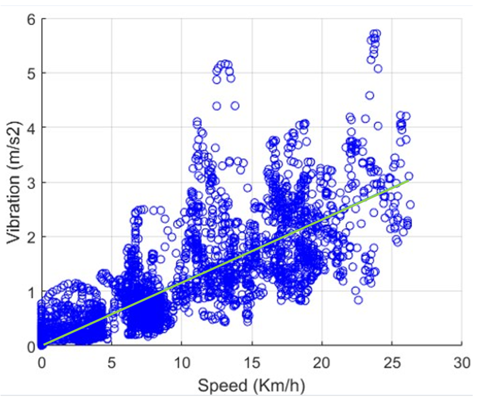
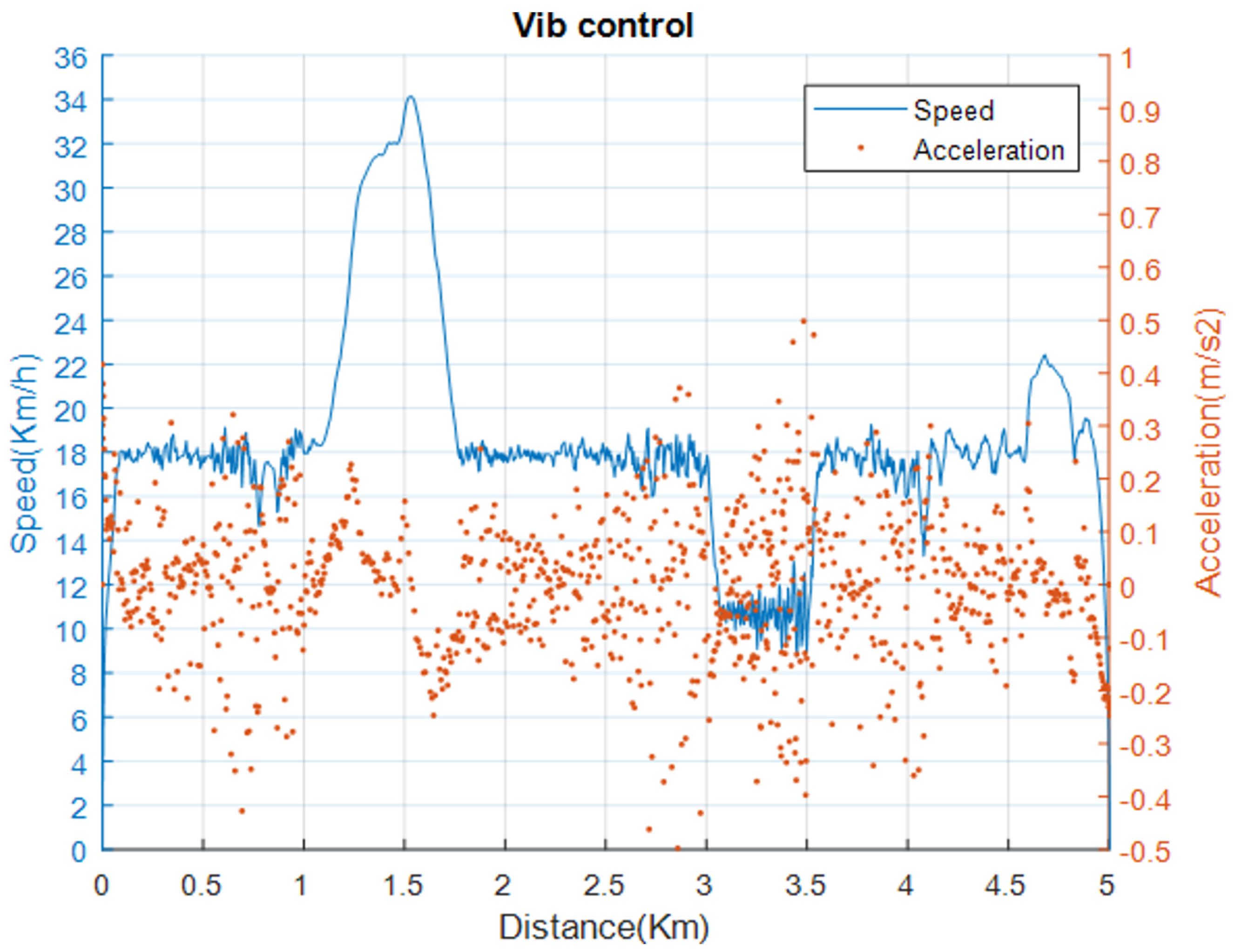
5.5. Vibration Reduction Control Performance

This section presents the second simulation described in Section 5.1 to evaluate the vibration reduction performance of the proposed RAVRS. To perform the simulation, the vibration model was formulated. Figure 15 presents the relationship between the speed of the e-bike and the vibration collected from the experimental trip on a rough road. It is clear that the RMS of vibration is proportional to the speed. The vibration model for the experimental roughness road is estimated using the first-degree polynomial equation expressed in Equation (19).
a z = f ( v ) = 0.4 v ( m / s 2 )
In the simulation, it is assumed that there is a rough road segment that lets the vibration of the e-bike be larger than the limitation. The rough road segment is from 3 to 3.5 km, and the e-bike vibration model is expressed in Equation (19). The limit vibration of the e-bike is set at 1.2 m/ s 2 . Figure 16 shows the results that explain that in the rough road segment from 3 to 3.5 km, the e-bike speed is maintained at 3 m/s, in accordance with Equation (19).
This section describes the experimental results related to this study. First, the e-bike dynamic model proposed in this study is verified by collecting the changes in the driving speed, pedal torque value T p , and motor assistance torque value T m through actual e-bike riding. T p and T m are input into the e-bike dynamic model for speed simulation and compared with the actual riding speed. The comparison results can be seen in Figure 12. Secondly, in both experiments in Section 5.3 and Section 5.4, the experimenters personally rode the e-bike for a distance of 5 km under different control strategies and collected data. The experiment in Section 5.3 compares the variations in speed and acceleration during the initial stage of riding an e-bike, as shown in Figure 13. It can be seen that the variations of the acceleration values of the proposed method are gentler and do not exceed 0.4 m/ s 2 in the initial stage of riding the e-bike. This implies that the proposed method does not produce sudden accelerations that would make the rider feel uncomfortable. In addition, in Figure 13d, the proposed method does not have a situation where the speed exceeds 18 km/h first and then gradually decreases in the speed variation range from 0 km/h to the preset 18 km/h (i.e., the riding distance is between 0 km and 0.1 km). The experimental results from Section 5.4 are shown in Table 6 and Figure 14. The comparison in Figure 14 shows that the proposed method is more capable of controlling the riding speed near the preset speed. That is, the variation in the velocity curve is smaller than that of the other methods used for comparison, and the acceleration value distribution interval is more concentrated. The experiments in Section 5.3 and Section 5.4 show that the proposed method has more stable speed control performance. Next, the experiment in Section 5.5 uses the data collected from the actual riding of an e-bike on a rough road to verify the control effectiveness of the proposed RAVRS on vibration suppression.

6. Conclusions

In this study, we propose a road-adaptive vibration reduction system for cyclists to ride PAP e-bikes with comfort and safety. The RAVRS guarantees riding comfort and safety by automatically selecting the appropriate assistance level for an e-bike to maintain the vibration, velocity, and acceleration within a smaller range of variation. The fuzzy PI control method designed for the RAVRS processes three input parameters (velocity error, acceleration, and vibration) and outputs the requested assistance level to the e-bike. Simulations with data collected from the experimental trips were conducted to verify and evaluate our design. The results show that in the case where it was uncertain if the parameter setting was optimal, the proposed method was superior to other methods, including manual, PID, and fuzzy1 methods (using only one input, i.e., speed error) due to the simultaneous consideration of multiple affecting parameters. In addition, the RAVRS can further enhance riding comfort through the proposed vibration reduction strategy. Although the proposed method cannot guarantee the expected speed when human torque is insufficient or when the e-bike is going downhill (due to the limited number of assistance levels of e-bikes), clearly our system can significantly improve riding quality and thus the riding experience.
In future work, safety and comfort rank evaluations will be the focal point of our research. We plan to investigate the user experience (UX) and the feeling of risk for cyclists who ride an e-bike in which the proposed RAVRS has been implemented for speed control. The resulting data will be used to improve our RAVRS to enhance the engagement of cyclists in road safety while achieving better vehicle speed management.

Author Contributions

Conceptualization, C.-R.D., V.-T.B. and S.-M.C.; methodology, V.-T.B., C.-R.D. and S.-M.C.; system implementation, V.-T.B. and S.-M.C.; performing the simulations and experiments, V.-T.B. and S.-M.C.; analysis of the simulation and experimental results, C.-R.D., V.-T.B. and C.-L.M.; writing—original draft preparation, V.-T.B., S.-M.C. and Y.-E.L.; writing—review and editing, C.-R.D., C.-L.M. and V.-T.B.; visualization, V.-T.B., S.-M.C. and Y.-E.L.; supervision, C.-R.D. All of the authors contributed significantly to the completion of this manuscript, in conceiving and designing the research, and in writing and improving the paper. All authors have read and agreed to the published version of the manuscript.

Funding

This research received no external funding.

Data Availability Statement

The original contributions presented in the study are included in the article, further inquiries can be directed to the corresponding author.

Conflicts of Interest

The authors declare no conflicts of interest.

References

  1. Taiwan’s Pathway to Net-Zero Emissions in 2050. Available online: https://www.ndc.gov.tw/en/Content_List.aspx?n=B154724D802DC488 (accessed on 20 April 2023).
  2. Chen, W.H.; Chen, I.; Lin, J.C.M.; Hsieh, I.Y.L. Role of hydrogen fuel cells in achieving road transport decarbonization: A case study from Taiwan. Int. J. Hydrogen Energy 2024, 80, 1182–1196. [Google Scholar] [CrossRef]
  3. Liao, F.; Correia, G. Electric carsharing and micromobility: A literature review on their usage pattern, demand, and potential impacts. Int. J. Sustain. Transp. 2022, 16, 269–286. [Google Scholar] [CrossRef]
  4. Bourne, J.E.; Leary, S.; Page, A.; Searle, A.; England, C.; Thompson, D.; Andrews, R.C.; Foster, C.; Cooper, A.R. Electrically assisted cycling for individuals with type 2 diabetes mellitus: A pilot randomized controlled trial. Pilot Feasibility Stud. 2023, 9, 60. [Google Scholar] [CrossRef] [PubMed]
  5. Boland, P.; Connell, L.; Thetford, C.; Janssen, J. Exploring the factors influencing the use of electrically assisted bikes (e-bikes) by stroke survivors: A mixed methods multiple case study. Disabil. Rehabil. 2022, 44, 1389–1398. [Google Scholar] [CrossRef]
  6. Bourne, J.E.; Kelly, P.; Armstrong, M.E.G. A Theory and Evidence-Informed e-Cycling Intervention for Individuals Diagnosed With Cancer: Development Study. JMIR Cancer 2024, 10, e54785. [Google Scholar] [CrossRef]
  7. Cairns, S.; Behrendt, F.; Raffo, D.; Beaumont, C.; Kiefer, C. Electrically-Assisted Bikes: Potential Impacts on Travel Behaviour. Transp. Res. Part A Policy Pract. 2017, 103, 327–342. [Google Scholar] [CrossRef]
  8. Bourne, J.E.; Cooper, A.R.; Kelly, P.; Kinnear, F.J.; England, C.; Lear, S.; Page, A. The Impact of E-Cycling on Travel Behaviour: A Scoping Review. J. Transp. Health 2020, 19, 100910. [Google Scholar] [CrossRef]
  9. Jiao, G.; Zhai, S. Design and Research of Real-Time Perception for Intelligent Power-Assisted Bicycles Based on Fuzzy Control. In Proceedings of the 2024 China Automation Congress (CAC), Qingdao, China, 1–3 November 2024. [Google Scholar]
  10. Genç, M.O. Data-driven model predictive control using road-based disturbance estimations in longitudinal driving of e-bike. J. Braz. Soc. Mech. Sci. Eng. 2024, 46, 204. [Google Scholar] [CrossRef]
  11. Lee, J.S.; Chen, Z.H.; Hong, Y. Enhancing Urban Mobility with Self-Tuning Fuzzy Logic Controllers for Power-Assisted Bicycles in Smart Cities. Sensors 2024, 24, 5. [Google Scholar] [CrossRef]
  12. Abagnale, C.; Cardone, M.; Iodice, P.; Strano, S.; Terzo, M.; Vorraro, G. Model-based Control for an Innovative Power-assisted Bicycle. Energy Procedia 2015, 81, 606–617. [Google Scholar] [CrossRef]
  13. Uyar, O.; Çunkaş, M.; Karaca, H. Enhanced intelligent control with adaptive system for electrically assisted bicycle. Eng. Sci. Technol. 2022, 30, 101047. [Google Scholar] [CrossRef]
  14. Li, Y.; Xu, L.; Huang, X.; Xiao, H. Research on Vibration Comfort of Non-Motorized Lane Riding Based on Three-Axis Acceleration. Appl. Sci. 2024, 14, 441. [Google Scholar] [CrossRef]
  15. Chitra, L.; Devabalaji, K.; Manobala, M.K.; Yogesh, S.; Raj, N. Design and Optimization of Light Weight Materials for E bike Chassis. In Proceedings of the 2024 15th International Conference on Computing Communication and Networking Technologies (ICCCNT), Kamand, India, 24–28 June 2024. [Google Scholar]
  16. Li, F.; Ma, P.; Wen, B. Optimization design and vibration reduction performance analysis of vehicle suspension structure. J. Vib. Control 2025. [Google Scholar] [CrossRef]
  17. Cui, B.Y.; Zhang, G.; Ma, Q.L. A stable velocity control strategy for a discrete-time car-following model. Phys. A Stat. Mech. Its Appl. 2021, 571, 125846. [Google Scholar] [CrossRef]
  18. Du, Y.C.; Chen, J.; Zhao, C.; Liu, C.L.; Liao, F.X.; Chan, C.Y. Comfortable and Energy-Efficient Speed Control of Autonomous Vehicles On Rough Pavements Using Deep Reinforcement Learning. Transp. Res. Part C Emerg. Technol. 2022, 134, 103489. [Google Scholar] [CrossRef]
  19. Nguyen, B.H.; Ocktaeck, L. A Review of History, Development, Design and Research of Electric Bcycles. Appl. Energy 2020, 260, 114323. [Google Scholar]
  20. Contò, C.; Bianchi, N. E-Bike Motor Drive: A Review of Configurations and Capabilities. Energies 2022, 16, 160. [Google Scholar] [CrossRef]
  21. Ebnealipour, S.; Tehrani, M.M.; Nazemian, H. A novel e-bike energy management for improvement of the rider metabolism. IET Intell. Transp. Syst. 2023, 17, 1925–2113. [Google Scholar] [CrossRef]
  22. Bravo, E.G.A.; de Sousa, F.A.S.F.; Escriba, C.; Acco, P.; Giraud, F.; Fourniols, J.Y.; Romero, G.S. Design and Validity of a Smart Healthcare and Control System for Electric Bikes. Sensors 2023, 23, 4079. [Google Scholar] [CrossRef]
  23. Neuber, H.; Strube, M. Closed-Loop heartrate Control with Electric Bicycles for Cardiac Rehabilitation. In Proceedings of the 2020 21st International Conference on Research and Education in Mechatronics (REM), Cracow, Poland, 9–11 December 2020. [Google Scholar]
  24. Meyer, D.; Körber, M.; Senner, V.; Tomizuka, M. Regulating the Heart Rate of Human–Electric Hybrid Vehicle Riders Under Energy Consumption Constraints Using an Optimal Control Approach. IEEE Trans. Control Syst. Technol. 2019, 27, 2125–2138. [Google Scholar] [CrossRef]
  25. Sweeney, S.; Ordóñez-Hurtado, R.; Pilla, F.; Russo, G.; Timoney, D.; Shorten, R. A Context-Aware E-Bike System to Reduce Pollution Inhalation While Cycling. IEEE Trans. Intell. Transp. Syst. 2019, 20, 704–715. [Google Scholar] [CrossRef]
  26. Iglesia, D.H.D.L.; Paz, J.F.D.; González, G.V.; Barriuso, A.L.; Bajo, J.; Corchado, J.M. Increasing the Intensity over Time of an Electric-Assist Bike Based on the User and Route: The Bike Becomes the Gym. Sensors 2018, 18, 220. [Google Scholar] [CrossRef] [PubMed]
  27. Tal, I.; Ciubotaru, B.; Muntean, G. Vehicular-Communications-Based Speed Advisory System for Electric Bicycles. IEEE Trans. Veh. Technol. 2016, 65, 4129–4143. [Google Scholar] [CrossRef]
  28. Morchin, W.C. Battery-powered electric bicycles. Proceedings of NORTHCON ’94, Seattle, WA, USA, 11–13 October 1994; pp. 269–274. [Google Scholar]
  29. E-Bike Instruction Manual Bosch Components; Riese & Müller GmbH: Weiterstadt, Germany, 2016. Available online: https://www.r-m.de/media/filer_public/0e/68/0e68a9ce-63ff-4529-b4d5-78ec67163f30/rum_ba_bosch_2017_en_160628_download.pdf (accessed on 11 May 2025).
  30. Precup, R.E.; Nguyen, A.T.; Blažič, S. A survey on fuzzy control for mechatronics applications. Int. J. Syst. Sci. 2024, 55, 771–813. [Google Scholar] [CrossRef]
  31. Hsu, R.C.; Liu, C.; Chan, D. A Reinforcement-Learning-Based Assisted Power Management with QoR Provisioning for Human–Electric Hybrid Bicycle. IEEE Trans. Ind. Electron. 2012, 59, 3350–3359. [Google Scholar] [CrossRef]
  32. Hsu, R.C.; Liu, C.; Lee, W.; Chen, C. A Reinforcement Learning Based Power Assisted Method with Comfort of Riding for Light Electric Vehicle. In Proceedings of the in 2010 IEEE 71st Vehicular Technology Conference, Taipei, Taiwan, 16–19 May 2010; pp. 1–5. [Google Scholar]
  33. Bui, V.-T.; Dow, C.-R.; Huang, Y.-C.; Liu, P.; Thai, V.D. A CANopen-Based Gateway and Energy Monitoring System for Electric Bicycles. Energies 2020, 13, 3766. [Google Scholar] [CrossRef]
  34. Schirmer, M.; Höpfner, H. Smartphone Hardware Sensors. Available online: https://www.uni-weimar.de/kunst-und-gestaltung/wiki/images/Zeitmaschinen-smartphonesensors.pdf (accessed on 11 May 2025).
  35. Múčka, P. International Roughness Index Thresholds Based on Whole-Body Vibration in Passenger Cars. Transp. Res. Rec. 2021, 2675, 305–320. [Google Scholar] [CrossRef]
  36. Zhao, Z.; Taghavifar, H.; Du, H.P.; Qin, Y.C.; Dong, M.M.; Gu, L. In-Wheel Motor Vibration Control for Distributed-Driven Electric Vehicles: A Review. IEEE Trans. Transp. Electrif. 2021, 7, 2864–2880. [Google Scholar] [CrossRef]
  37. Doria, A.; Marconi, E.; Munoz, L.; Polanco, A.; Suarez, D. An Experimental-Numerical Method for the Prediction of On-Road Comfort of City Bicycles. Veh. Syst. Dyn. 2021, 59, 1376–1396. [Google Scholar] [CrossRef]
  38. Ahmed, H.E.; Sahandabadi, S.; Bhawya; Ahamed, M.J. Application of MEMS Accelerometers in Dynamic Vibration Monitoring of a Vehicle. Micromachines 2023, 14, 923. [Google Scholar] [CrossRef]
  39. Wang, L. PID Control System Design and Automatic Tuning Using MATLAB/SIMULINK; John Wiley & Sons Ltd.: Hoboken, NJ, USA, 2020. [Google Scholar]
Figure 1. System overview.
Wevj 16 00276 g001
Figure 2. The proposed RAVRS architecture for e-bikes.
Wevj 16 00276 g002
Figure 3. Function graph of S L ( v ) for an e-bike with v = 24, v m a x = 28, N = 4, S 0 m a x = 0%, S 1 m a x = 100%, S 2 m a x = 220%, and S 3 m a x = 340%.
Wevj 16 00276 g003
Figure 4. Overview of the proposed fuzzy PI control mechanism.
Wevj 16 00276 g004
Figure 5. Basic architecture of the fuzzy control method.
Wevj 16 00276 g005
Figure 6. Velocity error membership functions.
Wevj 16 00276 g006
Figure 7. Acceleration membership functions.
Wevj 16 00276 g007
Figure 8. Vibration Deviation Membership Functions.
Wevj 16 00276 g008
Figure 9. User interfaces on a smartphone. (a) Main interface; (b) setting interface.
Wevj 16 00276 g009
Figure 10. Data collected from the experimental trip.
Wevj 16 00276 g010
Figure 11. Profiles of the road slope and human torque.
Wevj 16 00276 g011
Figure 12. Dynamic simulation of the e-bike with zero slope: (a) trip L = 0, (b) trip L = 1, (c) trip L = 2, and (d) trip L = 3.
Wevj 16 00276 g012
Figure 13. E-bike velocity and acceleration in the starting stage using the (a) manual, (b) fuzzy1, (c) PID, and (d) proposed methods.
Wevj 16 00276 g013
Figure 14. E-bike velocity and acceleration using the (a) manual, (b) fuzzy1, (c) PID, and (d) proposed methods.
Wevj 16 00276 g014
Figure 15. Vibration vs. speed.
Wevj 16 00276 g015
Figure 16. E-bike velocity and acceleration on the rough road segment (ranging from 3 to 3.5 km).
Wevj 16 00276 g016
Table 1. Main fuzzy inference rules.
a z d Output
Negative−1
Zero0
PositiveTable 2
Table 2. Fuzzy inference rules when the vibration deviation is positive.
Acceleration v ˙ Velocity Error v e
NegativeZeroPositive
Big negative+0.4+0.6+1.0
Medium negative+0.2+0.4+0.8
Small negative 0.2 +0.2+0.6
Zero 0.4 + 0.0 +1.0
Small positive 0.6 0.2 +0.6
Medium positive 0.8 0.4 + 0.0
Big positive 1.0 1.0 1.0
Table 3. Setting parameters for the fuzzy PI controller.
ParameterDescriptionValue
L m a x Maximum of assistance-level output L3
v * Expected velocity18 km/h
kRatio between middle gear and rear gear4
CZComfortable zone16 to 20 km/h
SZSafety zone−0.4 to 0.4 m/ s 2
V m a x Vibration limit1.2 m/ s 2
TController cycle time1 s
nNumber of samples of vibration per controller cycle time50
Table 4. Parameters of the S25 e-bike.
ParameterDescriptionValue
m 1 E-bike mass22 kg
r w Radius of the rear wheel27 in
kRatio between middle gear and rear gear4
NNumber of assistance levels4
v Velocity point from that the assistance ratio decreases24 km/h
v m a x Velocity point from that the assistance ratio is zero28 km/h
S 0 m a x Maximum assistance ratio when L = 00%
S 1 m a x Maximum assistance ratio when L = 1100%
S 2 m a x Maximum assistance ratio when L = 2220%
S 3 m a x Maximum assistance ratio when L= 3340%
Table 5. Environmental conditions.
ParameterDescriptionValue
μ Rolling friction coefficient0.008
gGravitational acceleration9.8 m/ s 2
C d Atmospheric drag coefficient0.5
A c Vehicle frontal area1 m 2
ρ Air density1.18 kg/ m 3
Table 6. Comparison of different control strategies for the stage after starting.
MethodRatio of Speed Control (%)Ratio of Acceleration Control (%)
Manual-99.37
PID80.6795.30
Fuzzy182.1398.01
Our proposed83.9799.79
Disclaimer/Publisher’s Note: The statements, opinions and data contained in all publications are solely those of the individual author(s) and contributor(s) and not of MDPI and/or the editor(s). MDPI and/or the editor(s) disclaim responsibility for any injury to people or property resulting from any ideas, methods, instructions or products referred to in the content.

