1. Introduction
To meet the high torque density requirements of electric vehicle drive motors, the d-axis and q-axis magnetic circuits of the motor rotor are often severely coupled, which can lead to a complex airgap flux distribution and generate additional electromagnetic force harmonics, resulting in increased motor vibration and noise. Therefore, the demand for research on vibration and noise in electric vehicle IPMSMs has been growing increasingly [
1].
The electromagnetic vibration of IPMSMs is primarily caused by radial excitation forces. Accurately calculating the excitation forces and determining the correlation between excitation forces and electromagnetic vibration are prerequisites for reducing vibration and noise in electric vehicle drive motors [
2]. Li et al. [
3] comprehensively analyzed the effects of windings, frame end caps, and temperature on the intrinsic frequency of the stator system and experimentally verified how each factor affects the intrinsic frequency of the motor. Yang et al. [
4] studied the effect of low-order radial force components on vibration and demonstrated that the minimum nonzero order of the radial force is equal to the greatest common divisor (GCD) of the motor’s pole and slot numbers. Typically, the amplitudes of the zeroth-order and minimum nonzero-order radial forces are large, leading to significant vibration, while higher-order radial forces have smaller amplitudes and contribute less to the vibration, often being ignored [
5]. With the development of the general airgap field modulation theory, the analysis of the motor’s physical significance has become increasingly clear [
6]. Fang et al. [
7] investigated the effect of high-order radial forces on the vibration of fractional-slot permanent magnet motors, finding that high-order radial forces can excite larger low-order vibrations under modulation. Wang et al. [
8] analyzed the effect of slot number order radial forces on the motor’s zeroth-order slot-frequency vibration using a 6-pole 36-slot IPMSM as an example. The results showed that, under modulation effects, slot number order radial forces can excite significant zeroth-order vibration.
The ultimate goal of analyzing radial excitation forces and establishing vibration mechanisms is to reduce the electromagnetic vibration of the motor. Methods such as stator skewing, stator tooth slot auxiliary slots, and segmented skewed rotor poles have been widely applied to vibration optimization in PMSMs. Wang et al. [
9] proposed a serrated skew structure to address the shortcomings of linear skewed poles and experimentally verified the effectiveness of this structure in suppressing motor vibration. Hong et al. [
10] introduced a permanent magnet pole structure with continuous skewed edges to reduce pole-frequency and slot-frequency vibrations, addressing the limitations of the skew slot method in vibration reduction. Peng et al. [
11] proposed a rotor segment structure with varying pole widths to reduce the zeroth-order vibration amplitude, overcoming the limitations of traditional skew slots and skewed pole methods in suppressing zeroth-order and pole-multiple order vibrations. Feng et al. [
12] analyzed the effect of skew slots on the suppression of sideband noise, compared it with a straight-slot motor, and experimentally validated the effectiveness of the skew slot method in reducing sideband noise. While these methods effectively suppress electromagnetic vibration in motors, they do not consider the impact of tooth modulation effects. Fang et al. [
13] proposed a hybrid vibration synthesis analysis method, considering both tooth modulation effects and tangential forces. Zhao et al. [
14] comprehensively evaluated the effects of magnetic field modulation, tooth modulation, and other factors, ultimately proposing an unequal tooth design to reduce the seventh-order harmonics generated by evenly distributed fractional-slot concentrated winding permanent magnet synchronous motors, thereby reducing the electromagnetic vibration produced by the motor. Wang et al. [
15] proposed a rotor structure with asymmetric magnetic poles and compared the oblique slot and linear oblique pole methods, the results show that the oblique slot method has the best optimization effect and the linear oblique pole has the worst optimization effect, which side by side reflects the limitation of the linear oblique pole on the optimization of vibration and noise performance of the motor.
This paper uses an 8-pole 48-slot IPMSM as an example to introduce in detail the modulated vibration characteristics of this type of motor. Then, a stepwise segmented skewed pole structure is proposed to suppress the modulated vibration excited by high-order radial forces, and its vibration reduction mechanism is analyzed. Finally, simulation analyses of the motor’s vibration and noise levels before and after optimization are conducted to validate the effectiveness of the proposed structure in suppressing motor vibration and noise.
3. Segmented Oblique Pole Modulation Vibration Damping Design
Different rotor deflection angles and segment numbers lead to varying improvements in the motor’s vibration performance. To achieve the best optimization effect, the total skew angle of the rotor segments is typically set to the angle of one stator tooth. For a 48-slot motor, the angle of one stator tooth is
, and the optimal basic deflection angle between rotor segments can be calculated using Equation (16):
where
is the basic deflection angle between rotor segments and
is the number of rotor segments (this paper takes the case of the rotor being evenly divided into 8 segments as an example).
After the rotor is segmented and skewed, the phase of the permanent magnet field is altered, but it does not affect the armature magnetic field. As the phase of the permanent magnet field changes, the radial magnetic flux density generated by the permanent magnet field also changes, and its average value can be expressed as follows:
From Equation (17), Equations (9) to (15) can be derived again. Under load conditions, the phase of the radial force harmonics generated by the
term and the
term will change, as shown in
Table 2.
When
, the 48th-order
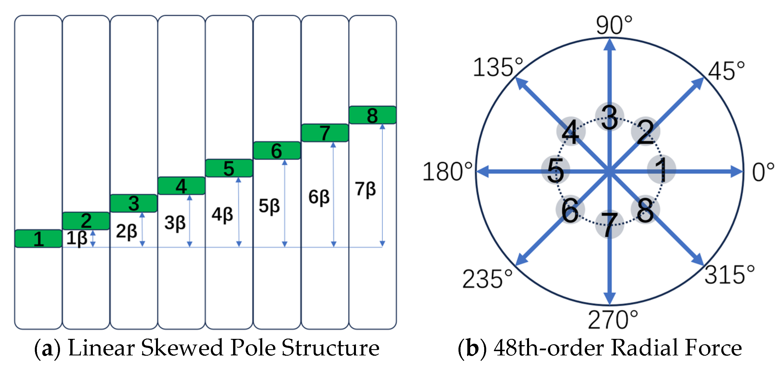
radial force generated by the motor will be deflected. If a linear segmented skewed pole structure is used, the deflection of the 48th-order radial force is shown in
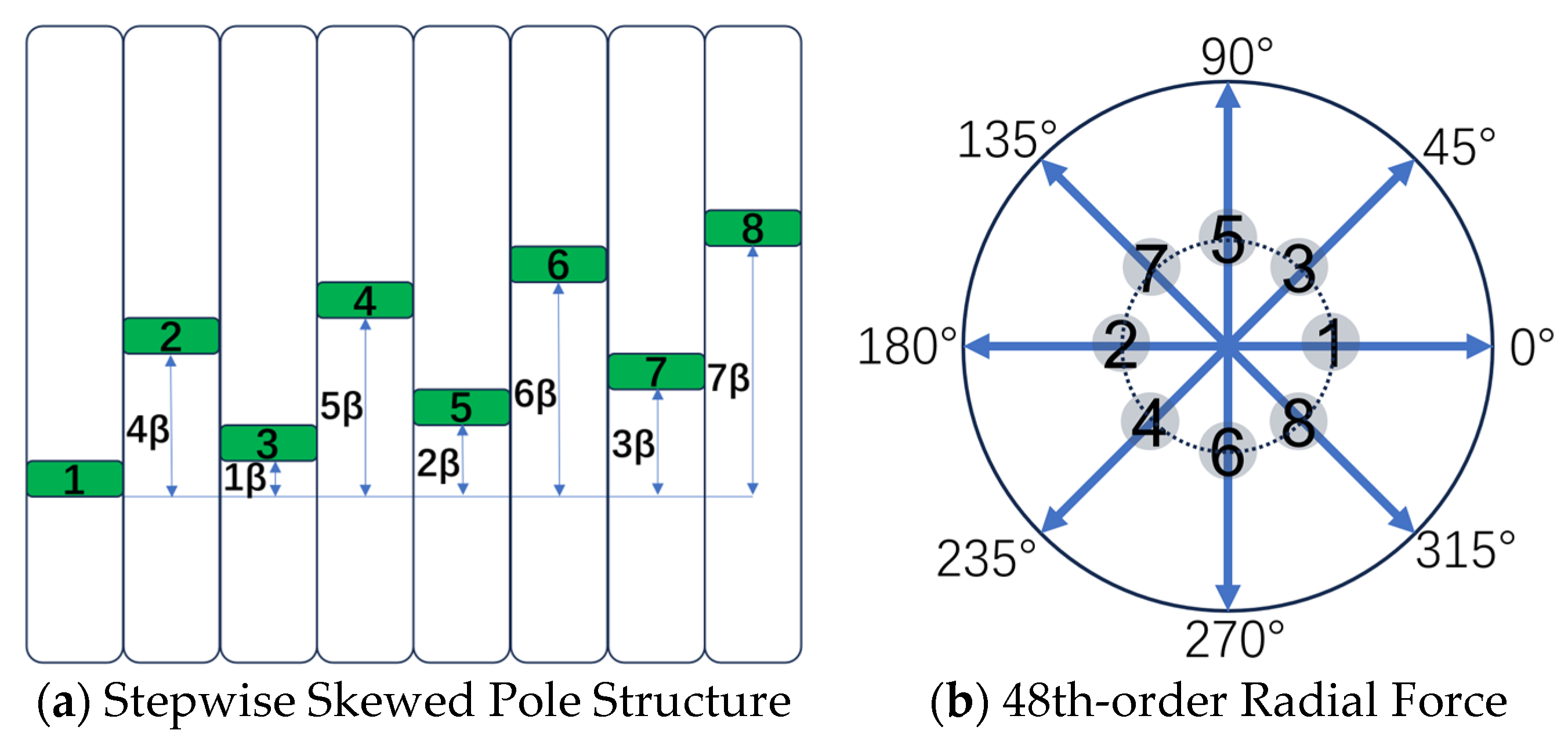
Figure 8. It can be seen that, when using the linear segmented skewed pole structure, the 48th-order radial forces generated by segments 1 and 5, 2 and 6, 3 and 7, and 4 and 8 cancel each other out in the circumferential direction. However, in the axial direction, for example, between segments 1 and 5, there exists an axial spacing of 3 rotor segments, which reduces the ideal cancelation effect of the 48th-order radial force.
To address the issues with the linear skewed pole structure, the arrangement order of the rotor segments is changed to form a stepwise segmented rotor skew structure, as shown in
Figure 9. Unlike the linear segmented skew structure, in the circumferential direction, the 48th-order radial forces generated by segments 1 and 2, 3 and 4, 5 and 6, and 7 and 8 cancel each other out, and there is no axial spacing between rotor segments.
To validate the advantages of the stepwise skew configuration, a comparative simulation analysis was conducted to evaluate the vibration acceleration amplitudes on the motor surface between linear skew and stepwise skew designs. The simulation implementation of segmented skew differs slightly from conventional methods, where both linear and stepwise skew angles for each rotor segment were configured in Maxwell 2D Model Settings while the 3D stator model was equally divided into eight axial sections. Additionally, to ensure accurate acquisition of
vibration acceleration results, the maximum frequency was set to 7100 Hz. The simulation results are presented in
Figure 10, demonstrating the effectiveness of the stepwise skew design in vibration suppression while maintaining torque performance. The analysis shows that the vibration acceleration at the stator surface at the
, caused by the 48th-order radial force, is 4687.3 mm/s
2. However, after adopting the stepwise skewed pole structure, the vibration acceleration at the
is reduced to 853.15 mm/s
2, which further validates the significant optimization effect of the stepwise structure on the motor’s
. Furthermore, significant reductions in vibration acceleration amplitudes were observed at the
,
, and
, while the remaining harmonic components exhibited relatively minor magnitudes that did not warrant detailed comparative analysis.
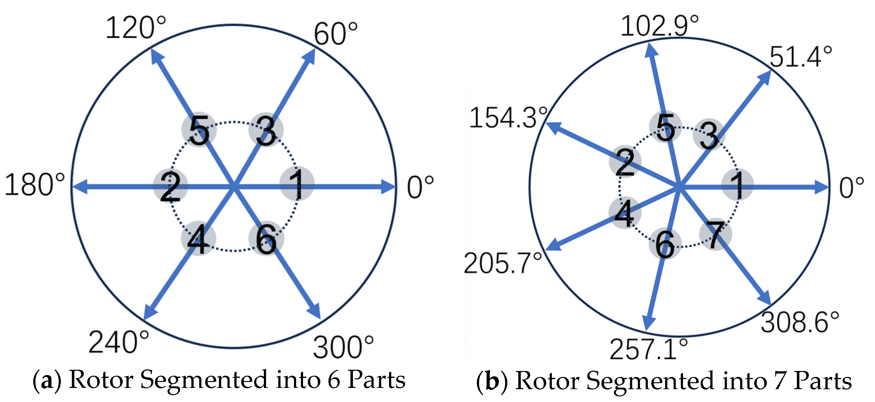
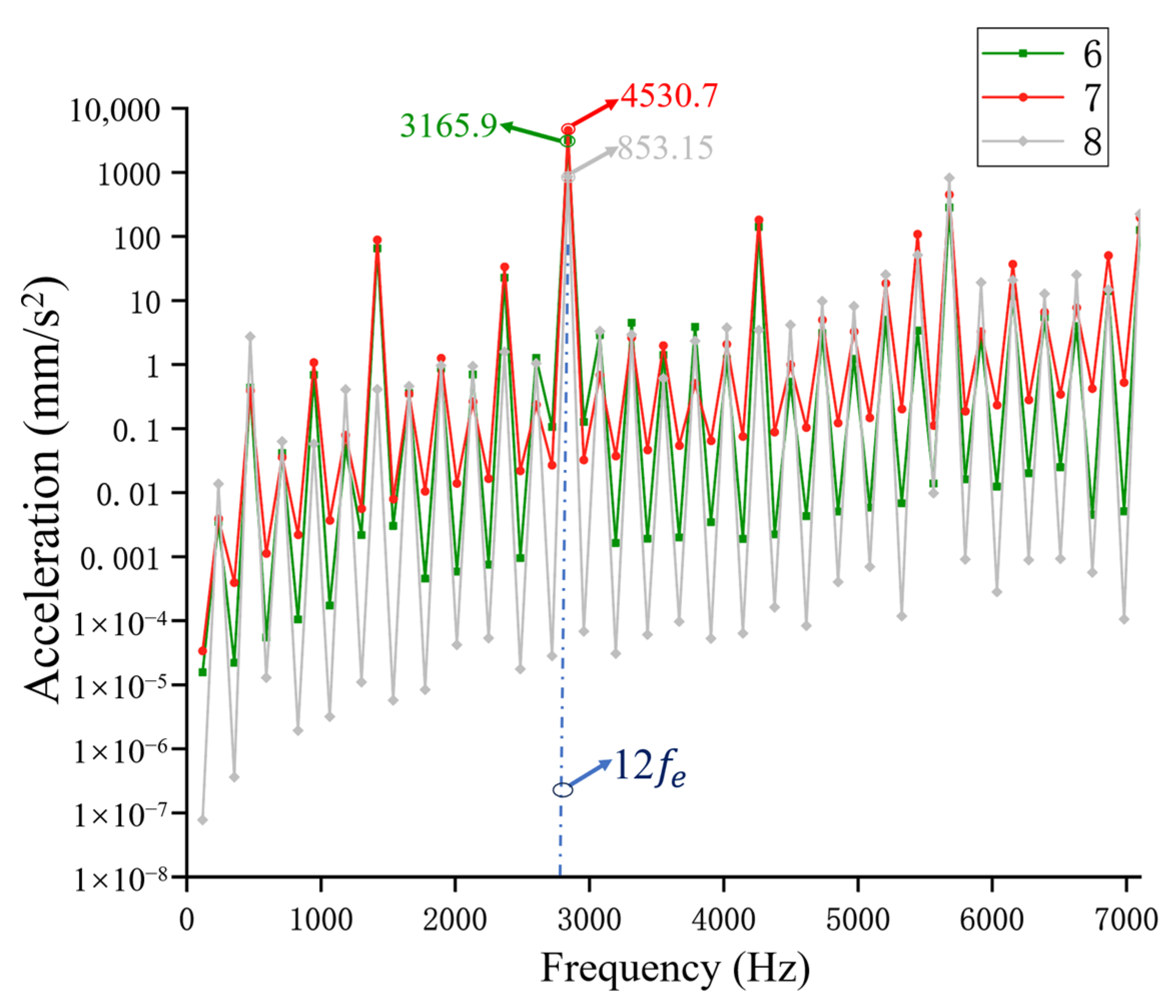
Additionally, the optimization performance of the stepwise skewed pole structure when the rotor is divided into 6, 7, and 8 segments was analyzed, as shown in
Figure 11 and
Figure 12. When the rotor is divided into an odd number of 7 segments, the radial force does not completely cancel in the circumferential direction, so the vibration acceleration at
is higher than the result with 6 segments. However, when the rotor is divided into 8 segments, the cancelation effect of the 48th-order radial force is ideal, and the vibration acceleration at
is minimized.
4. Analysis of Optimization Results
4.1. Analysis of Radial Force Optimization
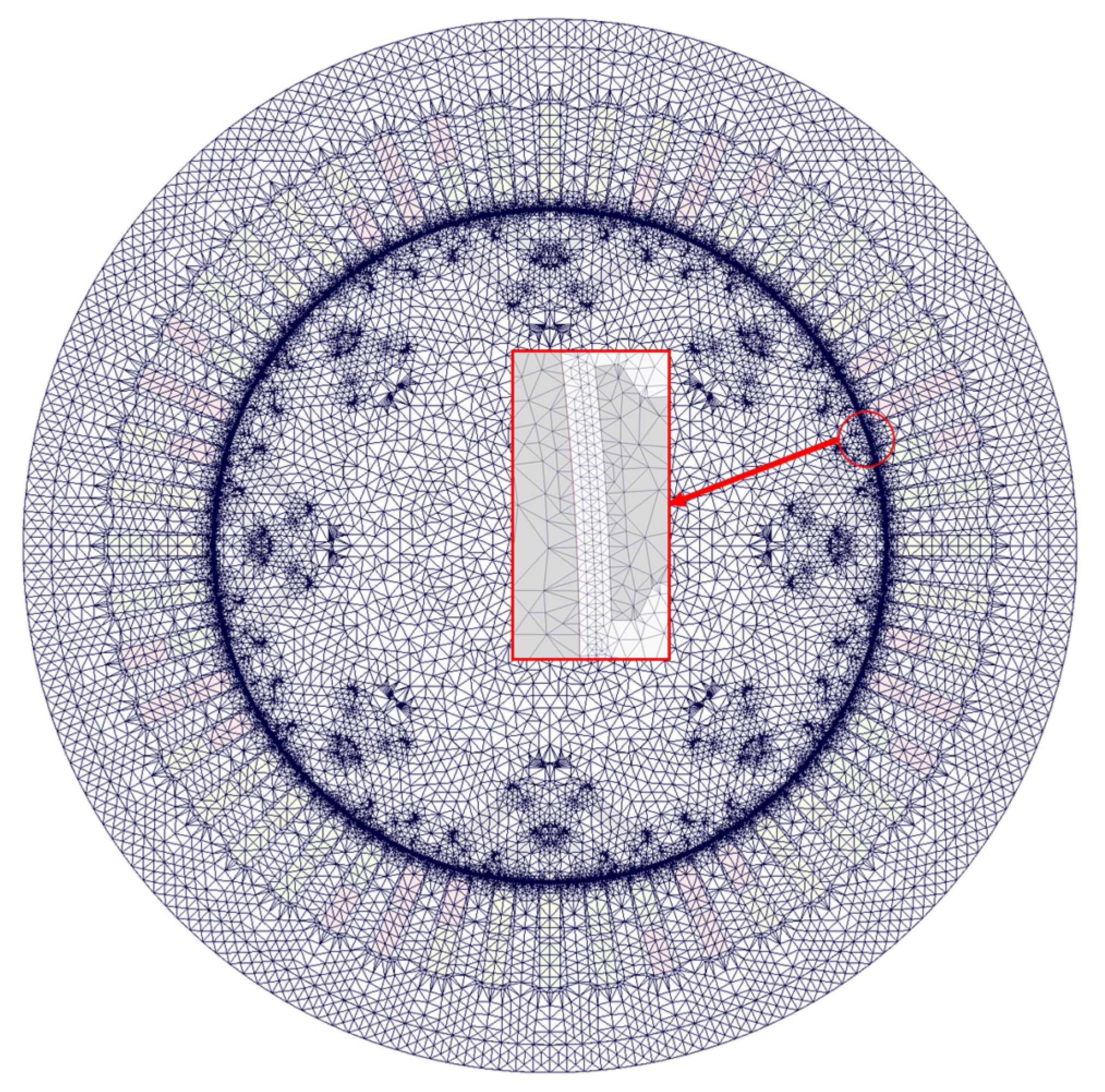
According to the two-dimensional motor model shown in
Figure 13, the radial electromagnetic force before and after optimization was simulated using the finite element method under the same load conditions. After segmentation of the skewed poles, the radial electromagnetic force density was calculated by averaging each segment’s radial force densities and performing a 2D fast Fourier decomposition on the results, as shown in
Figure 14.
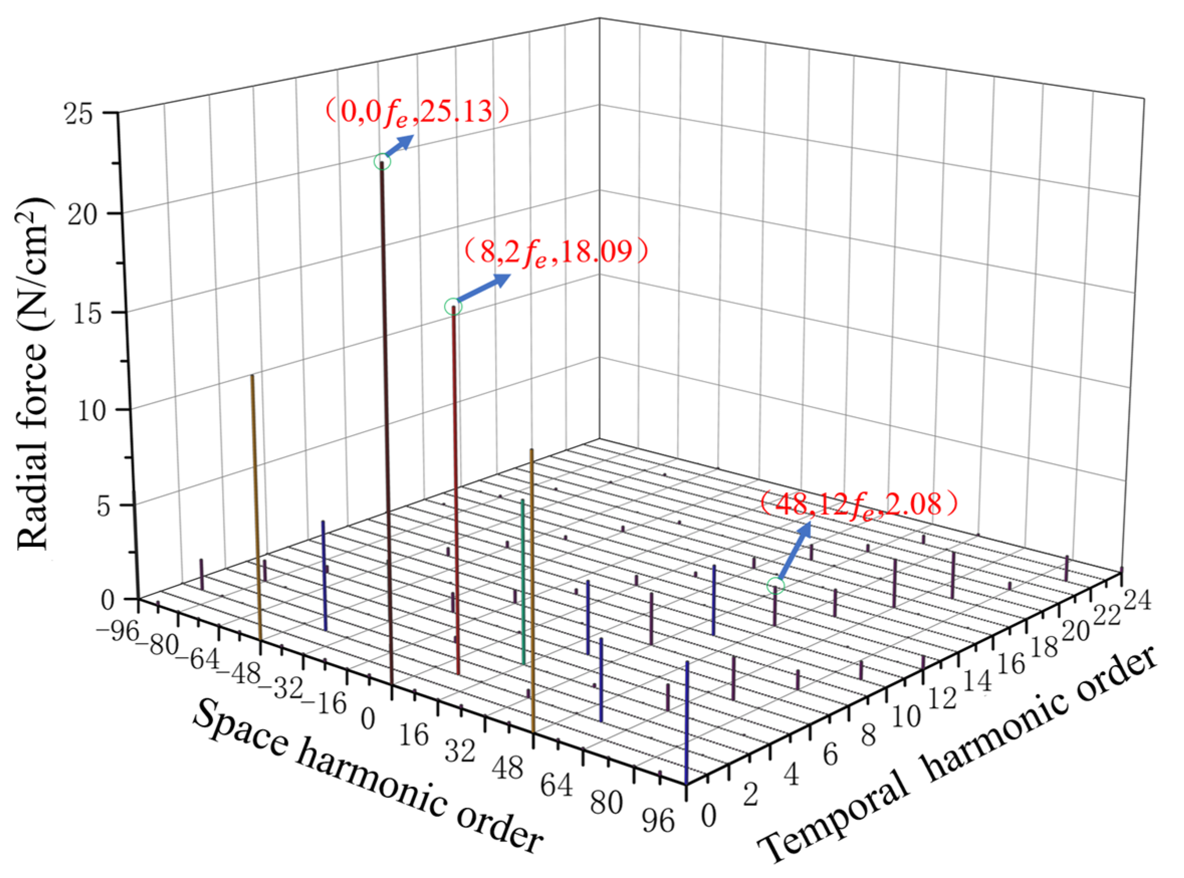
The results shown in
Figure 4 and
Figure 14 show that by adopting the stepwise segmented rotor skewed pole structure, the 48th-order
radial electromagnetic force density during load conditions is significantly reduced. Under the same load conditions, its value decreases from 2.08 N/cm
2 to 0.71 N/cm
2, a reduction of 68%. At the same time, the amplitudes of radial electromagnetic forces at higher harmonics (such as 0th, 8th, etc.) are also reduced, though these are not listed individually.
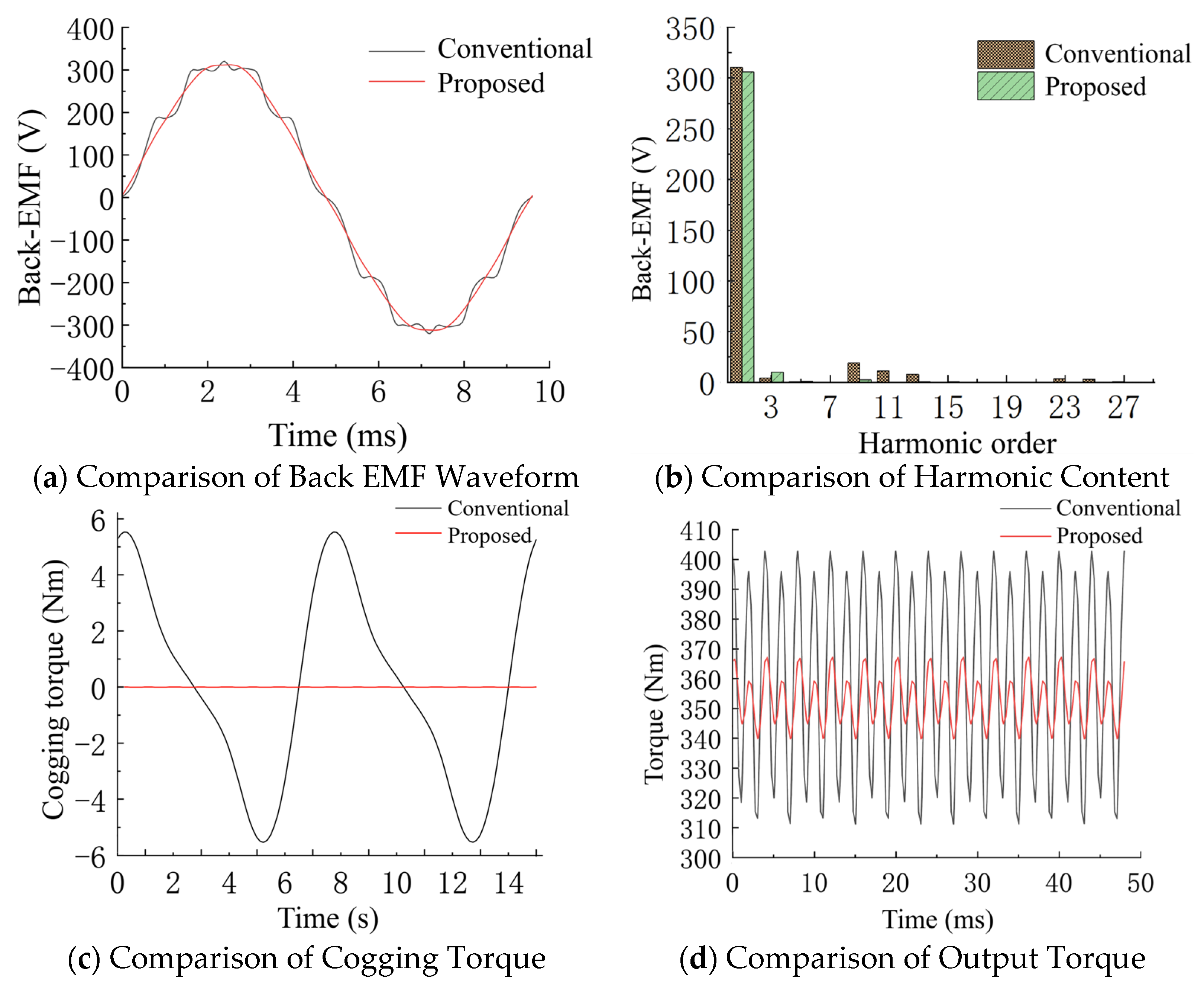
Additionally, after applying the stepwise segmented skewed pole structure, significant improvements were observed in the motor’s no-load back EMF harmonics, load torque fluctuations, and cogging torque, as shown in
Figure 15.
Typically, no-load back EMF harmonics, cogging torque, and load torque fluctuations all contribute to motor vibrations. From the comparison shown in
Figure 14, it can be seen that after the stepwise segmented rotor skewed pole structure is applied, the back EMF waveform of the motor exhibits better sinusoidal characteristics; the amplitudes of the various harmonics are also reduced. The peak-to-peak value of cogging torque is reduced from 11.39 Nm before optimization to 4.9 mNm after optimization; the output torque fluctuation is reduced from 87.25 Nm to 25.52 Nm. These optimizations in the data also indirectly indicate an improvement in the motor’s vibration performance.
4.2. Analysis of Vibration Performance Optimization
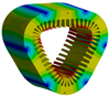
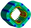
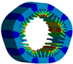
A simulation analysis of the motor’s vibration behavior before and after skewing was conducted to further verify the improvement in the motor’s vibration performance from the stepwise segmented rotor skewed pole structure. First, modal analysis of the stator and simplified housing models was performed, with the material properties of each component shown in
Table 3. The stator is made by laminating silicon steel sheets, and to make the simulation closer to actual conditions, anisotropic materials were assigned to the stator [
8].
Table 4 shows the natural frequencies of the stator housing’s modal shapes under both unconstrained and constrained (with the constraint applied to the circular hole in the housing shown in
Figure 13) conditions. It can be seen that the vibration frequency of the stator housing is not the same in the unconstrained (free mode) and constrained cases. When the fixed constraint is added at the circular hole mentioned above, it is equivalent to adding an infinite stiffness to the local area. The effective stiffness of the overall structure is also increased. Hence, the frequencies of the modes of each order of the constrained modes are higher than those of the unconstrained ones. The motors are usually fixedly mounted, so the constrained modes are utilized to carry out the next step of the vibration simulation.
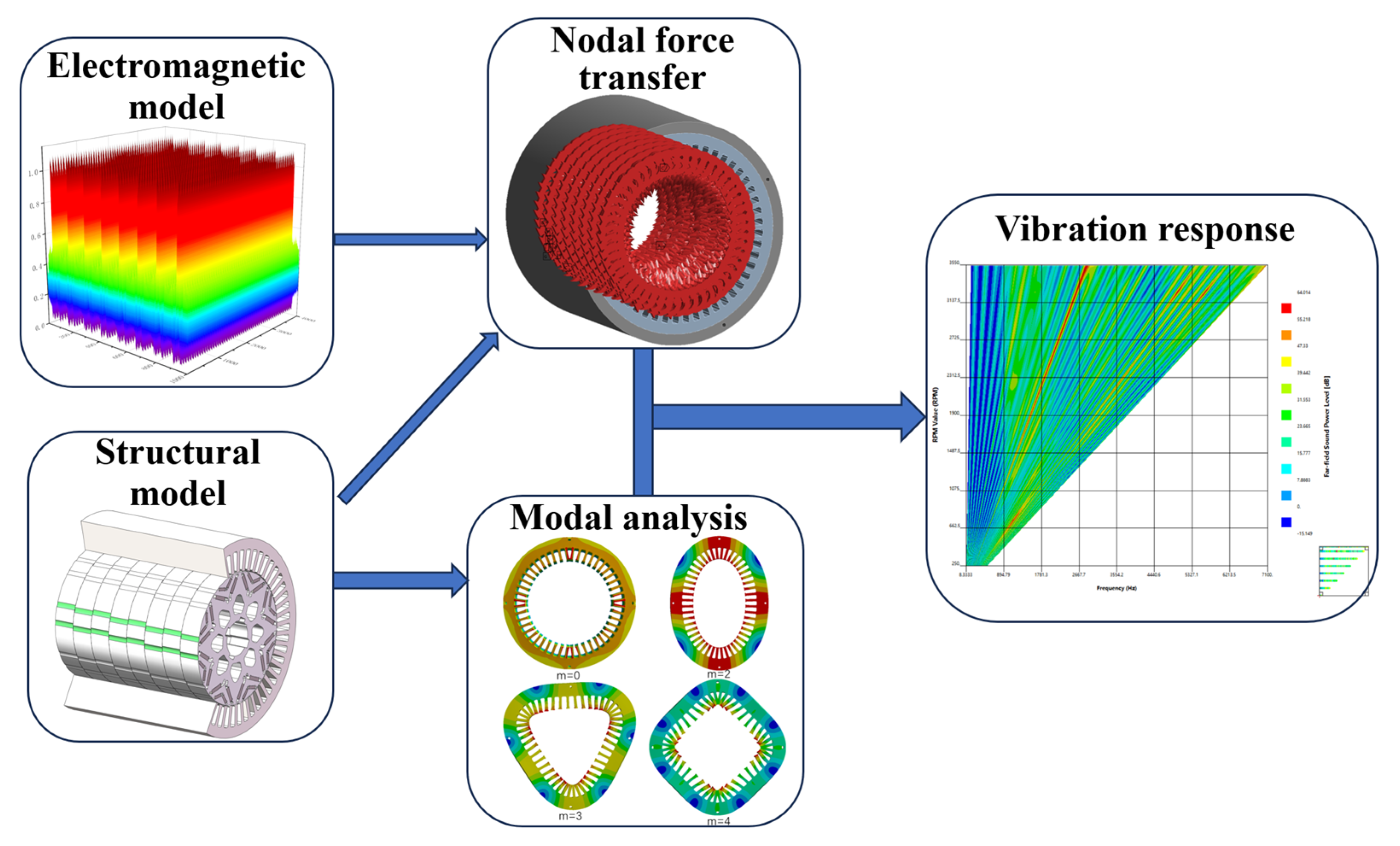
Next, based on the simulation process in
Figure 3, the electromagnetic forces after segmented skewing were imported into the structural field for coupled simulation. At the same time, the vibration acceleration results on the motor casing surface before and after optimization were observed at peak speed (3550 r/min), as shown in
Figure 16. When the motor operates at peak speed, the electrical frequency corresponding to
is 2840 Hz. According to the analysis of radial force modulation effects, the 48th-order
radial force is the primary excitation source for the
vibration. The vibration acceleration at the casing surface in this frequency range is 5635 mm/s
2, indicating that the vibration induced by the 48th-order
radial force is significant, consistent with the theoretical analysis.
At the same time, the electrical frequency corresponding to is 5680 Hz, which, similar to the analysis of radial force modulation effects at , shows that the primary excitation source for the vibration is the 96th-order radial force. The vibration acceleration at this frequency is 1337.9 mm/s2, and the vibration induced by the 96th-order radial force is also significant. After optimization using the stepwise segmented skewed pole structure proposed in this paper, the radial force vectors of slot-multiple orders generated by each rotor segment (such as the 48th-order radial force and the 96th-order radial force) are shifted and canceled out. The corresponding radial electromagnetic force density is reduced, and the excitation vibration acceleration decreases from 5635 mm/s2 at to 853.15 mm/s2, and from 1337.9 mm/s2 at to 821.06 mm/s2, representing reductions of 84% and 38%, respectively.
Finally, an air domain with a radius of 1 m is established centered on the motor, and the vibration results from the structural field are mapped to the acoustic field. The noise level caused by sound wave propagation is calculated through simulation.
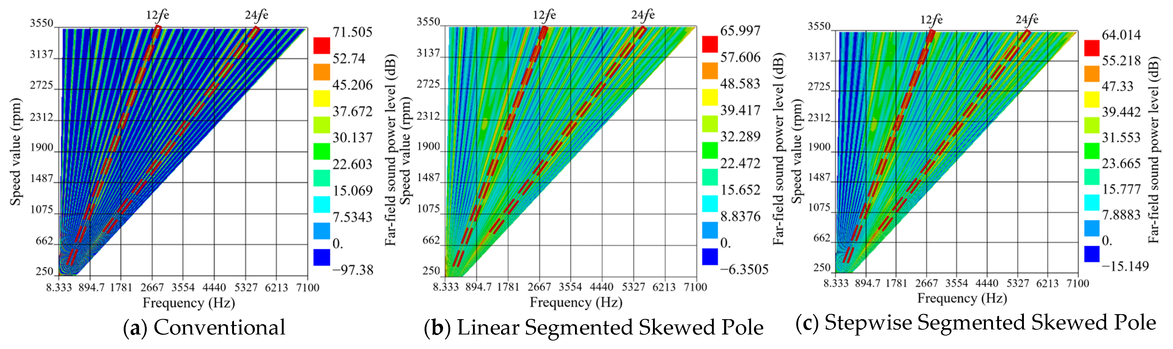
Figure 17 shows the noise waterfall diagram across the full speed range of the motor before optimization, after linear skewed pole optimization, and after stepwise skewed pole optimization.
The maximum electromagnetic noise generated by the motor is located in the frequency range, while the noise in the frequency range is relatively smaller but still warrants attention. Before optimization, the maximum electromagnetic noise was 71.505 dB, and after optimization, the maximum electromagnetic noise was reduced to 64.014 dB, showing a significant improvement in noise level. It should be noted that this step-skewing technique demonstrates excellent vibration and noise suppression for integer-slot permanent magnet synchronous motors (PMSMs). As this method is specifically designed for the structural configuration of integer-slot PMSMs, it is applicable not only to traction motors for electric vehicles but also to PMSMs for other applications. However, the method proves ineffective for fractional-slot PMSMs. Furthermore, during high-speed operation, the rotor’s mechanical strength and the motor’s thermal management system face significant challenges, making mechanical integrity tests and thermal analysis essential when necessary.
5. Conclusions
This study provides a detailed description of the generation mechanism of modulated vibration in the integer-slot IPMSM and the suppression mechanism of modulated vibration by the stepwise segmented skewed pole structure, and the following conclusions are drawn:
Due to the modulation effect in the integer-slot IPMSM, high-order radial forces are modulated into low-order radial forces under the influence of the stator slotted magnetic field, leading to larger vibrations. For the 8-pole 48-slot IPMSM studied in this paper, the 48th-order radial force is modulated into a zeroth-order radial force. Even though the amplitude of this order’s radial force is small, it will still cause significant vibration and noise.
The stepwise segmented rotor skewed pole method can suppress the motor’s modulated vibration. After skew optimization, the vibration acceleration at the harmonic on the motor casing surface is reduced from 5635 mm/s2 to 853.15 mm/s2, a reduction of 84%; the maximum electromagnetic noise is reduced from 71.505 dB to 64.014 dB, a decrease of 7.491 dB. The vibration and noise at the harmonic are also well suppressed.
Compared with the traditional linear skewed pole structure, the stepwise skewed pole structure does not increase the difficulty in motor manufacturing and assembly. Still, it offers better optimization of modulated vibration for the integer-slot permanent magnet synchronous motor. This skewed pole structure provides an additional option for vibration optimization design in motors.
In addition, this study has certain limitations. For example, only the stepwise segmented skewed pole structure was simulated, and no experimental validation was conducted. Future research could consider using experimental methods to further verify the accuracy of the simulation results and investigate the effects of control factors on motor vibration. In the future, based on the current simulation results, a prototype will be fabricated to test its output performance, etc. The simulation results will be de-calibrated based on the tested inverse electromotive force results. The simulation input parameters will be adjusted to narrow down the error to a reasonable range. At the same time, under the free boundary conditions (hanging the motor with a soft rope), the frequency response of several test points on the surface of the stator and the shell is tested by the hammering method. The results are fitted and compared with the simulation results. Then, the material properties inputted during the modal simulation test are adjusted. The simulation is performed several times to narrow the error, to make the simulation results of the vibration noise more in line with the actual situation.


