
Design and Implementation of a Wireless Power Transfer System for Electric Vehicles


Abstract
1. Introduction
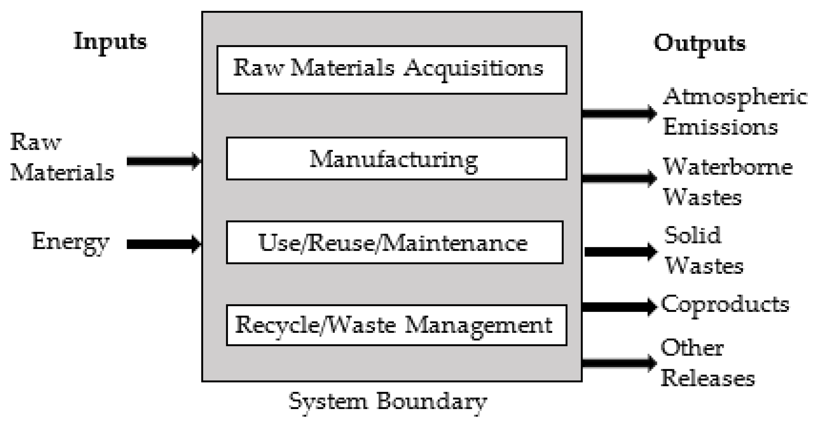
1.1. Life Cycle Assessment of WPT Systems
1.2. Safety of WPT Systems and Related Standards
- Electromagnetic compatibility (EMC): The WPT system must comply with electromagnetic compatibility requirements. This allows the device to operate in harmony with other electronic equipment and minimize electromagnetic interference [48].
- Foreign object detection (FOD): Wireless chargers must be able to detect foreign objects under the vehicle being charged. This prevents the device from accidentally operating on a foreign object and increases safety [28].
- Temperature control: Temperature sensors and control mechanisms should be used to reduce the risk of overheating during wireless charging [49].
- User safety: Wireless chargers should have features that protect the user [50].
- Compliance with standards: WPT systems must comply with relevant industry standards and regulations. This is important to ensure security and performance. The standards for WPT systems are as follows:
- SAE J2954 is a standard for WPT for EVs led by Society of Automotive Engineers (SAE) International. SAE J2954 establishes a methodology for designing and testing WPT systems for EVs up to power levels of 11 kW. SAE J2954 includes the powering frequency, electrical parameters, specifications, procedures, and other factors to be evaluated. It describes the specific dimensions for ground assembly (GA) and vehicle assembly (VA) components, including the power transmitting coil and receiving coil, respectively [51].
- IEC 61980-1 covers the general requirements for EV WPT systems including a general background and definitions (e.g., efficiency, electrical safety, EMC, and EMF). IEC 61980-2 specifically applies to magnetic field (MF) WPT for EVs and covers specific requirements for system activities and communication between the EV side and the off-board side including a general background and definitions. IEC 61980-3 covers specific power transfer requirements for the off-board side of MF-WPT for EVs (e.g., efficiency, electrical safety, EMC, and EMF) [52].
- ISO 19363:2020 defines the requirements and operation of the on-board vehicle equipment that enables magnetic field (MF) WPT for charging the traction battery of EVs. It is intended to be used for passenger cars and light duty vehicles [53].
1.3. Scalability of WPT Systems and Their Potential for Future Development
- Standardization and compatibility: The standardization of WPT systems ensures interoperability among different manufacturers and vehicle models. This promotes their wider adoption and scalability.
- Grid integration: Integrating WPT systems into the grid infrastructure allows for the deployment of charging points in various locations, such as parking lots, highways, and roadsides. This enhances scalability by providing more charging options.
- High efficiency and power levels: Improving the efficiency and power levels of WPT systems enables faster charging and the ability to charge multiple vehicles simultaneously, enhancing scalability.
- Cost and economic efficiency: Reducing the cost of WPT systems while improving economic efficiency can increase their adoption and scalability. Lower costs make the technology more accessible to a larger user base.
- Ubiquitous availability: Ensuring the widespread availability of wireless charging infrastructure increases scalability. This involves deploying charging points in a variety of locations to provide users with more convenient access.
- Higher power levels: WPT systems capable of operating at higher power levels would allow for faster charging.
- Smart charging management: Implementing smart charging management systems can optimize energy usage, improve efficiency, and balance the load on the grid.
- Automation and remote management: Automation and remote management features can make charging processes easier and more efficient.
- Energy storage integration: The integration of energy storage systems, such as battery storage, with WPT systems can increase energy efficiency and balance energy flow.
- Improvements in environmental and economic factors: Using more environmentally friendly materials, improving manufacturing processes, and reducing costs can enable WPT systems to reach a wider user base.
1.4. Validation Process and Reliability Tests of WPT Systems
- Conformance and validation standards: The validation process of WPT systems is generally carried out in line with international standards, especially standards such as SAE J2954. These standards include various tests that determine the suitability and performance of WPT systems.
- Electromagnetic compatibility (EMC) tests: EMC tests determine whether WPT systems are compatible with other devices in the electromagnetic spectrum. These tests are performed to ensure that electromagnetic radiation and interference are under control.
- Efficiency and safety tests: The efficiency and safety of WPT systems are tested. While efficiency tests determine how efficiently the system transfers energy, safety tests ensure that the system operates without harming people and the environment.
- Durability and environmental tests: WPT systems are subjected to various durability and environmental tests. These tests determine how the system performs in changing weather conditions and with long-term use.
- Compatibility tests: Compatibility tests are performed to determine whether WPT systems are compatible with different vehicle models and manufacturers. These tests are important to verify that the system is suitable for a wide range of users.
1.5. The User Experience and Integration Aspects of WPT Systems
- User-friendly design: WPT systems must have a user-friendly design. The location of charging points should be accessible and easy to use. Users should use minimal effort to start and stop charging.
- Automatic detection and start: WPT systems must automatically start charging by detecting the vehicle’s location. This allows users to charge their vehicles easily without any manual intervention.
- Security and protections: WPT systems must have various security and protection measures to ensure the safety of users and vehicles. These may include features such as short circuit protection, overcurrent protection, and leakage protection.
- Integration and smart charging management: WPT systems must have smart charging management features. These features can be used to improve energy efficiency, balance the load on the grid, and optimize users’ charging processes.
- Environmental awareness: WPT systems must demonstrate environmental sensitivity. This includes factors such as energy efficiency, the use of recycled materials, and waste management.
- Ease of integration: WPT systems should be easily integrated with EVs and grid infrastructure. This makes it easier for users to expand or improve charging infrastructure.
2. Materials and Methods
2.1. Effect of Coating Coils with Ferrite on Coupling Coefficient
2.2. Effect of Change in Number of Coil Windings on Coupling Coefficient
2.3. Effect of Coil Inner and Outer Radius Changes on Coupling Coefficient
2.4. Effect of Change in Distance between Coil Windings on Coupling Coefficient
2.5. System with Increased Coupling Coefficient
3. Simulation Results
4. Experimental Study
5. Results and Discussion
6. Conclusions
Funding
Data Availability Statement
Conflicts of Interest
References
- Kalwar, K.A.; Aamir, M.; Mekhilef, S. Inductively Coupled Power Transfer (ICPT) for Electric Vehicle Charging—A Review. Renew. Sustain. Energy Rev. 2015, 47, 462–475. [Google Scholar] [CrossRef]
- Pedder, D.A.G.; Brown, A.D.; Skinner, J.A. A Contactless Electrical Energy Transmission System. IEEE Trans. Ind. Electron. 1999, 46, 23–30. [Google Scholar] [CrossRef]
- Aditya, K.; Williamson, S.S. Design Considerations for Loosely Coupled Inductive Power Transfer (IPT) System for Electric Vehicle Battery Charging-A Comprehensive Review. In Proceedings of the 2014 IEEE Transportation Electrification Conference and Expo (ITEC), Dearborn, MI, USA, 15–18 June 2014. [Google Scholar] [CrossRef]
- Wu, H.H.; Gilchrist, A.; Sealy, K.D.; Bronson, D. A High Efficiency 5 KW Inductive Charger for EVs Using Dual Side Control. IEEE Trans. Ind. Inform. 2012, 8, 585–595. [Google Scholar] [CrossRef]
- Green, A.W.; Boys, J.T. 10 KHz Inductively Coupled Power Transfer-Concept and Control. In Proceedings of the 1994 Fifth International Conference on Power Electronics and Variable-Speed Drives, London, UK, 26–28 October 1994. [Google Scholar] [CrossRef]
- Covic, G.A.; Boys, J.T. Inductive Power Transfer. Proc. IEEE 2013, 101, 1276–1289. [Google Scholar] [CrossRef]
- Diekhans, T.; De Doncker, R.W. A Dual-Side Controlled Inductive Power Transfer System Optimized for Large Coupling Factor Variations and Partial Load. IEEE Trans. Power Electron. 2015, 30, 6320–6328. [Google Scholar] [CrossRef]
- Sun, K.; Niu, W. SPWM Inverter Control for Wireless Constant Current and Voltage Charging. World Electr. Veh. J. 2023, 14, 111. [Google Scholar] [CrossRef]
- Kan, T.; Nguyen, T.D.; White, J.C.; Malhan, R.K.; Mi, C.C. A New Integration Method for an Electric Vehicle Wireless Charging System Using LCC Compensation Topology: Analysis and Design. IEEE Trans. Power Electron. 2017, 32, 1638–1650. [Google Scholar] [CrossRef]
- Gbey, E.; Turkson, R.F.; Lee, S. A Bibliometric Survey of Research Output on Wireless Charging for Electric Vehicles. World Electr. Veh. J. 2022, 13, 37. [Google Scholar] [CrossRef]
- Takanashi, H.; Sato, Y.; Kaneko, Y.; Abe, S.; Yasuda, T. A Large Air Gap 3 KW Wireless Power Transfer System for Electric Vehicles. In Proceedings of the 2012 IEEE Energy Conversion Congress and Exposition (ECCE), Raleigh, NC, USA, 15–20 September 2012. [Google Scholar] [CrossRef]
- Chen, R.; Zheng, C.; Zahid, Z.U.; Faraci, E.; Yu, W.; Lai, J.S.; Senesky, M.; Anderson, D.; Lisi, G. Analysis and Parameters Optimization of a Contactless IPT System for EV Charger. In Proceedings of the 2014 IEEE Applied Power Electronics Conference and Exposition-APEC 2014, Fort Worth, TX, USA, 16–20 March 2014. [Google Scholar] [CrossRef]
- Keeling, N.A.; Covic, G.A.; Boys, J.T. A Unity-Power-Factor IPT Pickup for High-Power Applications. IEEE Trans. Ind. Electron. 2010, 57, 744–751. [Google Scholar] [CrossRef]
- Yilmaz, M.; Krein, P.T. Review of Battery Charger Topologies, Charging Power Levels, and Infrastructure for Plug-In Electric and Hybrid Vehicles. IEEE Trans. Power Electron. 2013, 28, 2151–2169. [Google Scholar] [CrossRef]
- Qiu, C.; Chau, K.T.; Liu, C.; Chan, C.C. Overview of Wireless Power Transfer for Electric Vehicle Charging. In Proceedings of the 2013 International Battery, Hybrid and Fuel Cell Electric Vehicle Symposium (EVS27), Barcelona, Spain, 17–20 November 2013. [Google Scholar] [CrossRef]
- Zhao, J.; Cai, T.; Duan, S.; Feng, H.; Chen, C.; Zhang, X. A General Design Method of Primary Compensation Network for Dynamic WPT System Maintaining Stable Transmission Power. IEEE Trans. Power Electron. 2016, 31, 8343–8358. [Google Scholar] [CrossRef]
- Bi, Z.; Kan, T.; Mi, C.C.; Zhang, Y.; Zhao, Z.; Keoleian, G.A. A Review of Wireless Power Transfer for Electric Vehicles: Prospects to Enhance Sustainable Mobility. App. Energy 2016, 179, 413–425. [Google Scholar] [CrossRef]
- Tan, L.; Pan, S.; Huang, X.; Xu, C. System Optimization for Wireless Power Transfer System with Double Transmitters. In Proceedings of the 2017 IEEE PELS Workshop on Emerging Technologies: Wireless Power Transfer (WoW), Chongqing, China, 20–22 May 2017. [Google Scholar] [CrossRef]
- Madawala, U.K.; Thrimawithana, D.J. A Bidirectional Inductive Power Interface for Electric Vehicles in V2G Systems. IEEE Trans. Ind. Electron. 2011, 58, 4789–4796. [Google Scholar] [CrossRef]
- Lin, F.Y.; Zaheer, A.; Budhia, M.; Covic, G.A. Reducing Leakage Flux in IPT Systems by Modifying Pad Ferrite Structures. In Proceedings of the 2014 IEEE Energy Conversion Congress and Exposition (ECCE), Pittsburgh, PA, USA, 14–18 September 2014. [Google Scholar] [CrossRef]
- Zhang, P.; Yang, Q.; Zhang, X.; Li, Y.; Li, Y. Comparative Study of Metal Obstacle Variations in Disturbing Wireless Power Transmission System. IEEE Trans. Magn. 2017, 53, 1–4. [Google Scholar] [CrossRef]
- Zhang, X.; Ni, X.; Yang, Q.; Wei, B.; Wang, S. Analysis of Electromagnetic Force on Metal Objects in Vertical Direction of Wireless Power Transfer. In Proceedings of the 2019 IEEE PELS Workshop on Emerging Technologies: Wireless Power Transfer (WoW), London, UK, 18–21 June 2019. [Google Scholar] [CrossRef]
- Bekiroglu, N.; Agcal, A.; Ozcira, S. Validation of Wireless Power Transfer by Using 3d Representation of Magnetically Coupled Resonators Considering Peak Efficiency. J. Magn. 2018, 23, 11–17. [Google Scholar] [CrossRef]
- Lee, S.; Jung, G.; Shin, S.; Kim, Y.; Song, B.; Shin, J.; Cho, D. The Optimal Design of High-Powered Power Supply Modules for Wireless Power Transferred Train. In Proceedings of the 2012 Electrical Systems for Aircraft, Railway and Ship Propulsion, Bologna, Italy, 16–18 October 2012. [Google Scholar] [CrossRef]
- Agcal, A.; Bekiroglu, N.; Ozcira, S. Comparison of Magnetic Resonant Coupling Wireless Power Transfer Systems within Aligned and Unaligned Positions and Determining Their Limits. J. Magn. 2016, 21, 652–659. [Google Scholar] [CrossRef]
- Aditya, K. Design and Characteristics of Series–Series and Series–Parallel Topologies Fed from Constant-Voltage Fixed-Frequency Supply. Sādhanā 2017, 42, 163–171. [Google Scholar] [CrossRef]
- Budhia, M.; Boys, J.T.; Covic, G.A.; Huang, C.Y. Development of a Single-Sided Flux Magnetic Coupler for Electric Vehicle IPT Charging Systems. IEEE Trans. Ind. Electron. 2013, 60, 318–328. [Google Scholar] [CrossRef]
- Hentschel, U.; Helwig, M.; Winkler, A.; Modler, N. Simulation of Foreign Object Detection Using Passive Inductive Sensors in a Wireless Charging System for Electric Vehicles. World Electr. Veh. J. 2023, 14, 241. [Google Scholar] [CrossRef]
- Liu, C.; Jiang, C.; Qiu, C. Overview of Coil Designs for Wireless Charging of Electric Vehicle. In Proceedings of the 2017 IEEE PELS Workshop on Emerging Technologies: Wireless Power Transfer (WoW), Chongqing, China, 20–22 May 2017. [Google Scholar] [CrossRef]
- Sallán, J.; Villa, J.L.; Llombart, A.; Sanz, J.F. Optimal Design of ICPT Systems Applied to Electric Vehicle Battery Charge. IEEE Trans. Ind. Electron. 2009, 56, 2140–2149. [Google Scholar] [CrossRef]
- Triviño-Cabrera, A.; González-González, J.M.; Aguado, J.A. Wireless Power Transfer for Electric Vehicles: Foundations and Design Approach, 1st ed.; Springer: Cham, Switzerland, 2020; pp. 6–74. [Google Scholar] [CrossRef]
- Stielau, O.H.; Covic, G.A. Design of Loosely Coupled Inductive Power Transfer Systems. In Proceedings of the 2000 International Conference on Power System Technology. Proceedings, Perth, WA, Australia, 4–7 December 2000. [Google Scholar] [CrossRef]
- Mahesh, A.; Chokkalingam, B.; Mihet-Popa, L. Inductive Wireless Power Transfer Charging for Electric Vehicles–A Review. IEEE Access 2021, 9, 137667–137713. [Google Scholar] [CrossRef]
- Chopra, S.; Bauer, P. Analysis and Design Considerations for a Contactless Power Transfer System. In Proceedings of the 2011 IEEE 33rd International Telecommunications Energy Conference (INTELEC), Amsterdam, The Netherlands, 9–13 October 2011. [Google Scholar] [CrossRef]
- García, X.D.T.; Vázquez, J.; Roncero-Sánchez, P. Design, Implementation Issues and Performance of an Inductive Power Transfer System for Electric Vehicle Chargers with Series–Series Compensation. IET Power Electron. 2015, 8, 1920–1930. [Google Scholar] [CrossRef]
- Wang, C.S.; Stielau, O.H.; Covic, G.A. Design Considerations for a Contactless Electric Vehicle Battery Charger. IEEE Trans. Ind. Electron. 2005, 52, 1308–1314. [Google Scholar] [CrossRef]
- Villa, J.L.; Sallan, J.; Osorio, J.F.S.; Llombart, A. High-Misalignment Tolerant Compensation Topology for ICPT Systems. IEEE Trans. Ind. Electron. 2012, 59, 945–951. [Google Scholar] [CrossRef]
- Wang, C.S.; Covic, G.A.; Stielau, O.H. Power Transfer Capability and Bifurcation Phenomena of Loosely Coupled Inductive Power Transfer Systems. IEEE Trans. Ind. Electron. 2004, 51, 148–157. [Google Scholar] [CrossRef]
- Bouanou, T.; El Fadil, H.; Lassioui, A.; Bentalhik, I.; Koundi, M.; El Jeilani, S. Design Methodology and Circuit Analysis of Wireless Power Transfer Systems Applied to Electric Vehicles Wireless Chargers. World Electr. Veh. J. 2023, 14, 117. [Google Scholar] [CrossRef]
- Zhang, Y.; Shen, Z.; Wu, Y.; Wang, H.; Pan, W. Dual-Side Phase-Shift Control for Strongly Coupled Series–Series Compensated Electric Vehicle Wireless Charging Systems. World Electr. Veh. J. 2022, 13, 6. [Google Scholar] [CrossRef]
- Bentalhik, I.; Lassioui, A.; EL Fadil, H.; Bouanou, T.; Rachid, A.; EL Idrissi, Z.; Hamed, A.M. Analysis, Design and Realization of a Wireless Power Transfer Charger for Electric Vehicles: Theoretical Approach and Experimental Results. World Electr. Veh. J. 2022, 13, 121. [Google Scholar] [CrossRef]
- Tan, P.; Peng, T.; Gao, X.; Zhang, B. Flexible Combination and Switching Control for Robust Wireless Power Transfer System with Hexagonal Array Coil. IEEE Trans. Power Electron. 2021, 36, 3868–3882. [Google Scholar] [CrossRef]
- Ramezani, A.; Narimani, M. Optimized Electric Vehicle Wireless Chargers with Reduced Output Voltage Sensitivity to Misalignment. IEEE J. Emerg. Sel. Top. Power Electron. 2019, 8, 3569–3581. [Google Scholar] [CrossRef]
- Zhou, J.; Yao, P.; Guo, K.; Cao, P.; Zhang, Y.; Ma, H. A Heterogeneous Inductive Power Transfer System for Electric Vehicles with Spontaneous Constant Current and Constant Voltage Output Features. Electronics 2020, 9, 1978. [Google Scholar] [CrossRef]
- Foote, A.; Costinett, D.; Kusch, R.; Mohammad, M.; Onar, O. Fourier Analysis and Loss Modeling for Inductive Wireless Electric Vehicle Charging with Reduced Stray Field. IEEE Trans. Transp. Electrif. 2024. [Google Scholar] [CrossRef]
- Scientific Applications International Corporation. Life Cycle Assessment: Principles and Practice. National Risk Management Research Laboratory Office of Research and Development, U.S. Environmental Protection Agency. 2006. Available online: https://nepis.epa.gov/Exe/ZyPDF.cgi/P1000L86.PDF?Dockey=P1000L86.PDF (accessed on 5 March 2024).
- Bi, Z.; De Kleine, R.; Keoleian, G.A. Integrated Life Cycle Assessment and Life Cycle Cost Model for Comparing Plug-in versus Wireless Charging for an Electric Bus System. J. Ind. Ecol. 2016, 21, 344–355. [Google Scholar] [CrossRef]
- Obayashi, S.; Tsukahara, H. EMC issues on wireless power transfer. In Proceedings of the 2014 International Symposium on Electromagnetic Compatibility, Tokyo, Japan, 12–16 May 2014. [Google Scholar]
- Zimmer, S.; Helwig, M.; Lucas, P.; Winkler, A.; Modler, N. Investigation of Thermal Effects in Different Lightweight Constructions for Vehicular Wireless Power Transfer Modules. World Electr. Veh. J. 2020, 11, 67. [Google Scholar] [CrossRef]
- Lin, J.C. Safety of Wireless Power Transfer. IEEE Access 2021, 9, 125342–125347. [Google Scholar] [CrossRef]
- Kim, D.; Kim, H.; Huang, A.; He, Q.; Zhang, H.; Ahn, S.; Zhu, Y.; Fan, J. Analysis and Introduction of Effective Permeability with Additional Air-gaps on Wireless Power Transfer Coils for Electric Vehicle Based on SAE J2954 Recommended Practice. Energies 2019, 12, 4797. [Google Scholar] [CrossRef]
- International Electrotechnical Commission. IEC 61980-1 EV WPT Systems. Available online: https://webstore.iec.ch/preview/info_iec61980-1%7Bed1.0%7Den.pdf (accessed on 5 March 2024).
- ISO 19363:2020; Electrically Propelled Road Vehicles, Magnetic Field Wireless Power Transfer, Safety and Interoperability Requirements. International Organization for Standardization: Geneva, Switzerland, 2020. Available online: https://www.iso.org/standard/73547.html (accessed on 5 March 2024).
- Sari, V. Design and Model of an Inductive Wireless Power Transfer System for Electric Vehicles. In Proceedings of the 4th International Congress on Natural and Applied Sciences, Rio de Janeiro, Brazil, 13–15 March 2023; Available online: https://www.iksadameica.org/_files/ugd/614b1f_f7b977c28570493dbd00b60ed7be97da.pdf (accessed on 5 March 2024).
- ON Semiconductor Corporation, Application Note 9020, IGBT Basic II. Available online: https://www.onsemi.com/pub/collateral/an-9020.pdf (accessed on 22 January 2024).
- Infineon Technologies, IR2113 High and Low Side Driver Datasheet. Available online: https://www.infineon.com/dgdl/Infineon-IR2110-DataSheet-v01_00-EN.pdf?fileId=5546d462533600a4015355c80333167e (accessed on 22 January 2024).


| Ref. | Power (W) | Compensation Topology | Distance (cm) | Frequency (KHz) | Efficiency (%) | Year |
|---|---|---|---|---|---|---|
| [4] | 5000 | LCL | 17.5–26.5 | 20 | 90 | 2012 |
| [7] | 3000 | SS | 10 | 35 | 95.8 | 2015 |
| [8] | 9 | SS | 3 | 43.2 | 80–92 | 2023 |
| [9] | 3000 | LCC | 15 | 85 | 95.5 | 2017 |
| [11] | 3000 | SP | 12–20 | 50 | 90 | 2012 |
| [12] | 4000 | SS | 4 | 80 | 97 | 2014 |
| [18] | 34 | SS | N/A | 100 | 91 | 2017 |
| [19] | 1500 | LCL | 4 | 20 | 85 | 2011 |
| [34] | 100 | SS | 5 | 105 | 83.2 | 2011 |
| [35] | 2180 | SS | 12.5 | 18.65 | 90 | 2015 |
| [37] | 2014 | SPS | 15 | 19.6 | 92 | 2011 |
| [39] | 3700 | SS | 12 | 85 | 90.02 | 2023 |
| [40] | 1200 | SS | 4 | 83.3 | 98 | 2022 |
| [41] | 500 | SS | 10–15 | 85 | 80 | 2022 |
| [42] | 266.9 | SS | 10 | 85 | 79.48 | 2021 |
| [43] | 500 | LCC | N/A | 85 | 95 | 2020 |
| [44] | 3000 | LCL | 30 | 85 | 95 | 2020 |
| [45] | 6600 | SS | 12.5 21 25 | 86.5 | 97.6 95.5 93.1 | 2024 |
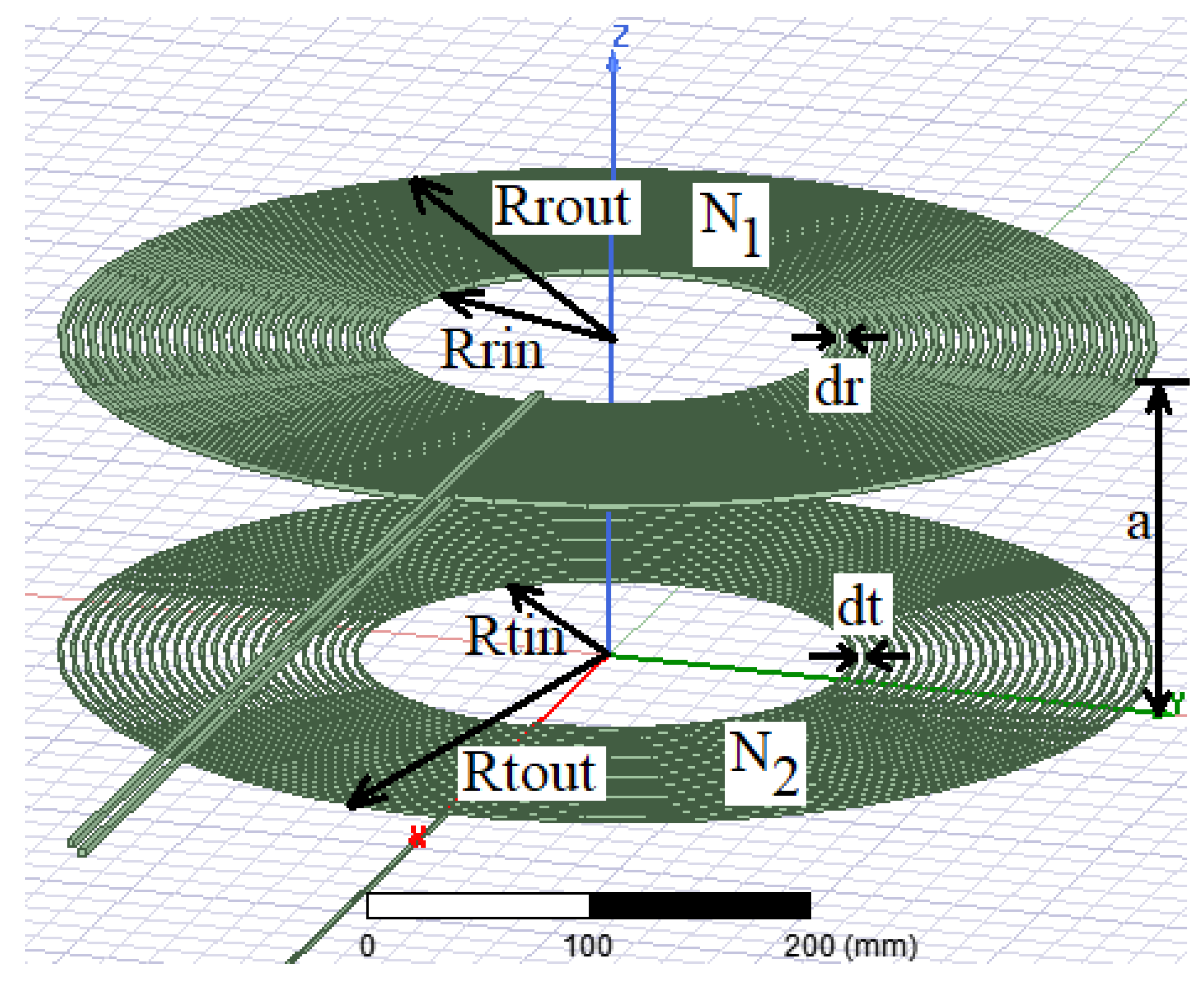
| a | Distance between coils | 200 mm |
| Tft | Transmitter ferrite thickness | 0 mm |
| Rft | Receiver ferrite thickness | 0 mm |
| N1 | Number of turns of the transmitter coil | 20 turns |
| N2 | Number of turns of the receiver coil | 20 turns |
| Rtin | Transmitter coil inner radius | 100 mm |
| Rrin | Receiver coil inner radius | 100 mm |
| Rtout | Transmitter coil outer radius | 250 mm |
| Rrout | Receiver coil outer radius | 250 mm |
| dt | Pitch length of transmitter coil | 7.5 mm |
| dr | Pitch length of receiver coil | 7.5 mm |
| k | Coupling coefficient | 0.1625 |
| L1 | Inductance of transmitter coil | 161.95 µH |
| L2 | Inductance of receiver coil | 155.74 µH |
| M | Mutual inductance | 25.66 µH |
| C1 | Transmitter capacitor | 391.41 nF |
| C2 | Receiver capacitor | 407.12 nF |
| Q1 | Transmitter quality factor | 9.791 |
| Q2 | Receiver quality factor | 3.911 |
| f0 | Resonant frequency | 20 KHz |
| Vsource | Input voltage (RMS) | 100 V |
| Isource | Input current (RMS) | 40.4 A |
| Pin | Input power | 4040 W |
| VL | Load voltage (RMS) | 125.79 V |
| IL | Load current (RMS) | 25.15 A |
| PL | Output power | 3163 W |
| RL | Load | 5 Ω |
| η | Efficiency | 78.3 |
| k | Rft (mm) | ||||||
|---|---|---|---|---|---|---|---|
| 0 | 1 | 2 | 3 | 4 | 5 | ||
| Tft (mm) | 0 | 0.1625 | 0.1819 | 0.1831 | 0.1842 | 0.1847 | 0.1851 |
| 1 | 0.1832 | 0.2074 | 0.2094 | 0.2102 | 0.2108 | 0.2112 | |
| 2 | 0.1847 | 0.2095 | 0.2109 | 0.2123 | 0.2129 | 0.2133 | |
| 3 | 0.1855 | 0.2104 | 0.2123 | 0.2132 | 0.2138 | 0.2143 | |
| 4 | 0.1860 | 0.2110 | 0.2130 | 0.2139 | 0.2145 | 0.2149 | |
| 5 | 0.1864 | 0.2115 | 0.2135 | 0.2144 | 0.2149 | 0.2154 | |
| k | N2 | |||||||||
|---|---|---|---|---|---|---|---|---|---|---|
| 12 | 13 | 14 | 15 | 16 | 17 | 18 | 19 | 20 | ||
| N1 | 12 | 0.1048 | 0.1081 | 0.1115 | 0.1147 | 0.1176 | 0.1205 | 0.1227 | 0.1251 | 0.1273 |
| 13 | 0.1085 | 0.1120 | 0.1156 | 0.1189 | 0.1221 | 0.1248 | 0.1274 | 0.1301 | 0.1325 | |
| 14 | 0.1120 | 0.1156 | 0.1194 | 0.1230 | 0.1263 | 0.1295 | 0.1321 | 0.1349 | 0.1374 | |
| 15 | 0.1152 | 0.1194 | 0.1233 | 0.1268 | 0.1303 | 0.1337 | 0.1365 | 0.1395 | 0.1422 | |
| 16 | 0.1183 | 0.1224 | 0.1265 | 0.1304 | 0.1341 | 0.1374 | 0.1407 | 0.1438 | 0.1466 | |
| 17 | 0.1212 | 0.1254 | 0.1297 | 0.1339 | 0.1378 | 0.1414 | 0.1449 | 0.1480 | 0.1510 | |
| 18 | 0.1239 | 0.1285 | 0.1328 | 0.1371 | 0.1412 | 0.1450 | 0.1484 | 0.1520 | 0.1552 | |
| 19 | 0.1264 | 0.1312 | 0.1356 | 0.1401 | 0.1444 | 0.1484 | 0.1520 | 0.1556 | 0.1592 | |
| 20 | 0.1287 | 0.1336 | 0.1383 | 0.1429 | 0.1473 | 0.1516 | 0.1553 | 0.1592 | 0.1625 | |
| 21 | 0.1308 | 0.1359 | 0.1407 | 0.1455 | 0.1502 | 0.1545 | 0.1585 | 0.1625 | 0.1663 | |
| 22 | 0.1327 | 0.1381 | 0.1430 | 0.1480 | 0.1528 | 0.1573 | 0.1615 | 0.1656 | 0.1696 | |
| 23 | 0.1346 | 0.1400 | 0.1453 | 0.1502 | 0.1552 | 0.1599 | 0.1644 | 0.1685 | 0.1727 | |
| 24 | 0.1362 | 0.1418 | 0.1470 | 0.1523 | 0.1574 | 0.1623 | 0.1670 | 0.1713 | 0.1755 | |
| 25 | 0.1377 | 0.1434 | 0.1488 | 0.1542 | 0.1594 | 0.1645 | 0.1693 | 0.1740 | 0.1782 | |
| 26 | 0.1390 | 0.1449 | 0.1506 | 0.1559 | 0.1613 | 0.1665 | 0.1715 | 0.1763 | 0.1806 | |
| K | Rrin (mm) Rrout (mm) | |||||||
|---|---|---|---|---|---|---|---|---|
| 70 220 | 80 230 | 90 240 | 100 250 | 110 260 | 120 270 | 130 280 | ||
| Rtin (mm) Rtout (mm) | 80 230 | 0.1382 | 0.1434 | 0.1481 | 0.1522 | 0.1557 | 0.1585 | 0.1607 |
| 90 240 | 0.1425 | 0.1482 | 0.1533 | 0.1578 | 0.1617 | 0.1650 | 0.1676 | |
| 100 250 | 0.1462 | 0.1523 | 0.1579 | 0.1625 | 0.1672 | 0.1709 | 0.1740 | |
| 110 260 | 0.1493 | 0.1558 | 0.1618 | 0.1672 | 0.1721 | 0.1763 | 0.1798 | |
| 120 270 | 0.1521 | 0.1587 | 0.1652 | 0.1710 | 0.1764 | 0.1810 | 0.1850 | |
| 130 280 | 0.1540 | 0.1613 | 0.1679 | 0.1742 | 0.1800 | 0.1851 | 0.1896 | |
| 140 290 | 0.1553 | 0.1630 | 0.1700 | 0.1767 | 0.1829 | 0.1885 | 0.1935 | |
| 150 300 | 0.1561 | 0.1641 | 0.1717 | 0.1788 | 0.1852 | 0.1913 | 0.1967 | |
| 160 310 | 0.1565 | 0.1647 | 0.1726 | 0.1801 | 0.1869 | 0.1936 | 0.1993 | |
| 170 320 | 0.1563 | 0.1647 | 0.1729 | 0.1808 | 0.1882 | 0.1949 | 0.2012 | |
| k | dr | ||||||
|---|---|---|---|---|---|---|---|
| 6 | 6.5 | 7 | 7.5 | 8 | 8.5 | ||
| dt | 6 | 0.1627 | 0.1629 | 0.1628 | 0.1629 | 0.1625 | 0.1620 |
| 6.5 | 0.1628 | 0.1630 | 0.1630 | 0.1631 | 0.1627 | 0.1623 | |
| 7 | 0.1625 | 0.1629 | 0.1632 | 0.1630 | 0.1627 | 0.1625 | |
| 7.5 | 0.1622 | 0.1628 | 0.1629 | 0.1625 | 0.1625 | 0.1623 | |
| 8 | 0.1616 | 0.1624 | 0.1625 | 0.1624 | 0.1621 | 0.1620 | |
| 8.5 | 0.1613 | 0.1618 | 0.1619 | 0.1618 | 0.1616 | 0.1615 | |
| a | Distance between coils | 200 mm |
| Tft | Transmitter ferrite thickness | 3 mm |
| Rft | Receiver ferrite thickness | 1 mm |
| N1 | Number of turns of the transmitter coil | 26 turns |
| N2 | Number of turns of the receiver coil | 20 turns |
| Rtin | Transmitter coil inner radius | 170 mm |
| Rrin | Receiver coil inner radius | 130 mm |
| Rtout | Transmitter coil outer radius | 352 mm |
| Rrout | Receiver coil outer radius | 270 mm |
| dt | Pitch length of transmitter coil | 7 mm |
| dr | Pitch length of receiver coil | 7 mm |
| St | Transmitter coil cross section | 2.5 mm2 |
| Sr | Receiver coil cross section | 4 mm2 |
| k | Coupling coefficient | 0.2671 |
| L1 (µH) | Inductance of transmitter coil | 729.064 |
| L2 (µH) | Inductance of receiver coil | 311.86 |
| M (µH) | Mutual inductance | 127.39 |
| C1 (nF) | Transmitter capacitor | 86.94 |
| C2 (nF) | Receiver capacitor | 203.26 |
| Q1 | Transmitter quality factor | 1.78 |
| Q2 | Receiver quality factor | 7.83 |
| f0 | Resonant frequency | 20 KHz |
| Vsource | Input voltage (RMS) | 200 V |
| RL | Load | 2.5, 5, 10 Ω |
| From the Model | According to Equation (13) | |||||
|---|---|---|---|---|---|---|
| RL | RL | |||||
| 2.5 Ω | 5 Ω | 10 Ω | 2.5 Ω | 5 Ω | 10 Ω | |
| Vin (V) | 200 | 200 | 200 | 200 | 200 | 200 |
| I1 (A) | 2.0578 | 3.6915 | 6.9747 | 2.0578 | 3.6915 | 6.9747 |
| Pin (W) | 411.56 | 738.3 | 1394.94 | |||
| VL (V) | 27.6137 | 54.8187 | 107.7277 | |||
| IL (A) | 11.0455 | 10.9637 | 10.7728 | |||
| PL (W) | 305 | 601 | 1160.5 | 434.04 | 698.39 | 1246.56 |
| η (%) | 74.11 | 81.4 | 83.19 | |||
| RL | |||
|---|---|---|---|
| 2.5 Ω | 5 Ω | 10 Ω | |
| Vin (V) | 200 | 200 | 200 |
| I1 (A) | 1.95 | 3.47 | 6.76 |
| Pin (W) | 390 | 694 | 1352 |
| VL (V) | 25.43 | 51.67 | 104.53 |
| IL (A) | 10.28 | 9.71 | 9.68 |
| PL (W) | 261.42 | 501.71 | 1011.85 |
| η (%) | 67.03 | 72.29 | 74.84 |
Disclaimer/Publisher’s Note: The statements, opinions and data contained in all publications are solely those of the individual author(s) and contributor(s) and not of MDPI and/or the editor(s). MDPI and/or the editor(s) disclaim responsibility for any injury to people or property resulting from any ideas, methods, instructions or products referred to in the content. |
© 2024 by the author. Licensee MDPI, Basel, Switzerland. This article is an open access article distributed under the terms and conditions of the Creative Commons Attribution (CC BY) license (https://creativecommons.org/licenses/by/4.0/).
Share and Cite
Sari, V. Design and Implementation of a Wireless Power Transfer System for Electric Vehicles. World Electr. Veh. J. 2024, 15, 110. https://doi.org/10.3390/wevj15030110
Sari V. Design and Implementation of a Wireless Power Transfer System for Electric Vehicles. World Electric Vehicle Journal. 2024; 15(3):110. https://doi.org/10.3390/wevj15030110
Chicago/Turabian StyleSari, Vekil. 2024. "Design and Implementation of a Wireless Power Transfer System for Electric Vehicles" World Electric Vehicle Journal 15, no. 3: 110. https://doi.org/10.3390/wevj15030110
APA StyleSari, V. (2024). Design and Implementation of a Wireless Power Transfer System for Electric Vehicles. World Electric Vehicle Journal, 15(3), 110. https://doi.org/10.3390/wevj15030110