Abstract
The reduction in driving range and the degradation of vehicle performance in cold weather has become one of the challenges in vehicle electrification in recent years. The root cause of this phenomenon is the property of lithium-ion batteries with capacity and power capability reduction at low temperatures. In this study, an external battery heating system was developed by employing an electrothermal film affixed to the surface of each cell, and the heating process was performed during driving. An equivalent circuit model combined with a thermal model was established for the simulation and control design. A fuzzy logic control strategy was developed to optimize the external heating power provided by the battery pack, and to achieve the maximum range by the end of discharge. A global optimal control strategy obtained by dynamic programming and a constant maximum power heating strategy were used for comparison. Simulation and experimental validations show that the proposed fuzzy logic control algorithm can achieve a 3.6% to 5.3% improvement in driving range than the maximum power heating method, and has close performance to the global optimal solution. Furthermore, the vehicle equipped with the proposed heating system can have up to 150.4% of the range recovery under different driving conditions.
1. Introduction
Electrification of vehicles has become a promising solution to the increasingly worsening environmental issues and the energy crisis in recent years, along with the considerable progress in key components and technologies in electric vehicles [1,2]. Compared with the traditional vehicles equipped with an internal combustion engine consuming fossil energy, EVs show great advantages, including less greenhouse gas and harmful emissions, due the usage of traction batteries and clean energy. Compared with other secondary batteries, lithium-ion batteries are more suitable for EVs because of their advantages of high specific energy, low self-discharge, and long cycle life [3,4]. However, with the popularization of EVs in an increasingly wide area with various climates, a common issue has gained more and more attention, which is that the performance of EVs is severely diminished at low temperatures, including a reduced driving range, weakened acceleration and a loss of regenerative braking. It was reported that the total driving range could be reduced by 40% to 60% under different cold conditions [5,6]. The reduced performance of the vehicle is caused by the reduced capacity and diminished charging and discharging power limits of lithium-ion batteries at low temperatures, and this is mainly due to poor electrolyte conductivity, poor lithium intercalation kinetics at the SEI-covered electrode surfaces, poor ionic diffusion in the electrode bulk [7], and the instability of lithiated graphite phases [8]. Therefore, a battery heating system and strategy for cold weather conditions is urgently needed to heat up the battery temperature to a normal operating range and guarantee satisfactory vehicle performance.
To implement the battery heating system, accessional hardware needs to be added inside or outside the battery pack, and the corresponding control logic needs to be included in the battery management system (BMS). Based on the where the heat is generated, battery heating can be classified into external and internal heating [9]. External heating generally uses a heating source outside the cells and transfers the heat to the cells convectively, and the commonly used heat transfer materials include air, liquid and a electrothermal heater [10]. Among these methods, air heating and liquid heating systems are commonly integrated with a cooling system. For air heating, air is heated by an external heating device, and a fan creates a convective flow around the pack [11,12]. For liquid heating, the battery can be heated by either immersing it in direct contact with the liquid, or by placing pipes containing the liquid inside the battery pack. Because of the higher thermal conductivity, the heating rate and uniform temperature distribution can be greatly improved [13]. For electrothermal element heating, usually, the elements are directly attached to the surface of the battery, and there are several different approaches in terms of the electrothermal materials, such as positive temperature coefficient (PTC) material [14], electrothermal jackets [15], wide-line metal film [16], polyimide film [17], CNT based film [18], Peltier effect element [19], and pulsating heat pipe [20], etc. External heating methods have the advantage of easy implementation. However, the uneven distribution of temperature between different cells can be harmful for pack operation and lead to safety issues, and the temperature rise rate is relatively slow. Temperature rise rates of 0.35 °C/min to 0.69 °C/min were reported in [21,22], which imply that a preheating time of approximately 20 min to 1 h is required to warm up the battery before driving.
Distinct from that of external heating, the basic mechanism of internal heating is to use the heat generation from a cell’s internal resistance by imposing an alternating current or a direct current through the battery. Compared with external heating, internal heating can achieve a higher temperature rise rate; a rate of 2.21 °C/min achieved by AC heating was reported in [23] and a rate of 4.29 °C/min achieved by AC heating was reported in [24]. In detail, the AC heating method has high heating efficiency, good temperature uniformity, no battery energy consumption and less impact on battery health [24]. However, the implementation of AC heating highly depends on the availability of AC generation facilities, which limits the application in Evs. In contrast to AC heating, the DC heating method directly discharges the energy in the battery; thus, there is no additional equipment required [25]. However, a large discharge current rate with a long duration could increase the battery’s capacity fade [26]; thus, a more complicated control mechanism is required, such as modifying the DC constant current to a bidirectional pulsed current [27].
Although considerable progress has been made in terms of the faster heating speed, slower battery degradation, and implementable facilities in battery heating, there is always a trade-off between shortening heating time and maintaining battery lifetime reduction. The major reason is that most studies have focused on battery preheating, hence the heating duration is not allowed to be long. Few studies reported on battery heating during driving, which could reduce the heat rate, the complexity of the system and the costs.
The main purpose of this study is to develop an external battery heating system which heats up the battery during driving instead of before driving, and to develop a control strategy governing the heating power aimed to maximize the driving range before the battery runs out of the available energy at low temperatures. An electrothermal film was adopted as the heating material for its high heat conductivity, small thickness, light weight and even distribution of temperature [28]. The battery provides the required power to heat up itself through an external path during driving. In order to achieve the longest driving range under different conditions, the heating power must be controlled to deal with the trade-off between the temperature rise rate and heating energy consumption. Dynamic programming (DP) is a widely used approach in energy management problems of electric vehicles for solving energy optimization problems and achieving global optimality [29,30], including internal battery heating optimization [31]. However, DP requires preknowledge of the driving cycle, which makes it difficult to apply the algorithm in online cases. Furthermore, the huge calculation amount impedes the industrial implementation of DP in production controllers [32]. The fuzzy logic control (FLC) algorithm is an alternative approach in energy management system control design and optimization owing to its effectiveness and simplicity in decision-making for complex systems [33,34]. Compared with DP, FLC utilizes more information from domain experts and relies less on the mathematical modeling of a physical system, and it does not require preknowledge about the cycle information, thus guaranteeing online calculation ability and control robustness [35,36]. In this study, an FLC strategy is developed to control the external heating power under different driving conditions to optimize the driving range. The key contributions of this article are as follows:
(1) An external battery heating system which warms up the battery during driving is proposed. Compared with the existing preheating systems, heating during driving allows a longer heating duration; thus, the required heating power is significantly reduced, which brings benefits to battery health.
(2) Electrothermal film is utilized as the material of the heater which is powered by the battery itself through a DC/DC converter. The light weight and small size of the film does not affect the energy density of the battery pack, and there is no necessity to change the structure of the pack. The film-based heater is suitable for pouch cells and prismatic cells. However, it is not a proper solution to cylindrical cells.
(3) A fuzzy control logic is designed to control the heating power which can obtain a suboptimal solution under a low computational load and is hence suitable for the promotion of industrialization. The proposed external battery heating system and control strategy could benefit vehicle driving at low temperatures by extending the driving range and eliminating the preheating time.
The rest of this paper is organized as follows. Section 2 introduces the configuration of an external battery heating system and presents an electrical and thermal model of the system. Section 3 proposes a fuzzy logic control strategy to optimize the external heating power based on driving conditions. Section 4 presents the experimental validation and simulation results, and several conclusions are drawn in Section 5.
2. System Modeling
2.1. System Configuration
The target vehicle in this study is a pure electric vehicle with a battery pack consisting of 300 battery cells, and at normal temperatures it has a driving range of approximately 125 miles. The type of the cell is a lithium ferrous phosphate (LFP) pouch, and the main parameters are shown in Table 1.

Table 1.
Cell parameters.
An external heating approach with electrothermal film was adopted in this study and polyimide was taken as the base material for its good thermal stability. The film was attached to the surface of the cell, as shown in Figure 1a. The films were parallelly connected inside each battery module, as shown in Figure 1b. Figure 1c shows a real battery module equipped with the electrothermal films and terminal wires connecting to the DC/DC converter. Table 2 gives the main parameters of the film.
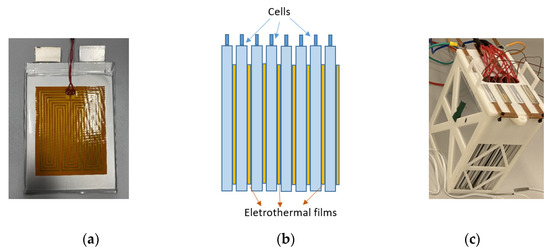
Figure 1.
External heater. (a) Front view of the electrothermal film attached to the surface of a pouch cell; (b) side view sketch of a battery module with the cells and external heater in parallel connection; (c) battery module equipped with an external heater for experimental validation.

Table 2.
Electrothermal film parameters.
An overall block diagram of the external battery heating system is shown in Figure 2. The vehicle control unit (VCU) receives the driver’s command by reading the pedal position signal, calculates the load power and sends it to the battery management system (BMS). The BMS also monitors the voltage, current and temperature of the battery cell/pack. The developed external battery heating control strategy is also implemented in the BMS, and executes the fuzzy logic control algorithm to obtain the external heating power. A DC/DC buck converter powered by the battery pack receives the heating power command, adjusts the output voltage to guarantee the battery heater operating with the desired heating power. In summary, the external battery heater consumes the energy from the battery cells, warms up the cells and recovers the available energy of the battery pack, and no additional heating facilities are required.
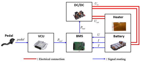
Figure 2.
Block diagram of the battery external heating system.
For the purpose of designing and tuning the control strategy, and validating it in real driving conditions before the testing vehicle is ready, it was essential to develop a mathematical model of the battery heating system, which could represent the electrical and thermal behavior of the battery with high accuracy, and replace the real battery heating system in an offline simulation or hardware-in-the-loop (HIL) simulation. The detailed model will be illustrated in the following subsections.
2.2. Equivalent Circuit Model
The equivalent circuit model with the second-order RC circuit approach was employed to model the battery cell, as shown in Figure 3.
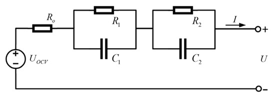
Figure 3.
Equivalent circuit model of the battery cell.
In this model, Ro is the ohmic resistance which represents the static character of the battery cell that satisfies the Ohm’s law. The two pairs of RC circuits represent the dynamic character of the battery cell which is caused by the polarization phenomenon, in which R1 is the activation polarization resistance, R2 is the concentration polarization resistance, and C1 and C2 are the polarization capacitances, respectively. UOCV is the open-circuit voltage of the cell, and U is the output voltage of the cell. Uo is the voltage drop on Ro, U1 and U2 are the polarization voltages on R1 and R2, respectively, and I is the current. The dynamics of the model can be represented by the following equations.
Hybrid pulse power characteristic (HPPC) tests were performed at different temperatures and SOEs to obtain the values of equivalent circuit model parameters. The reason for using SOE (state of energy) instead of SOC (state of charge) is the convenience of calculation at different temperatures and statuses. SOC is defined with the definition of the battery capacity by the amp-hour integral, where the Coulomb efficiency appears in the amp-hour integral equation; however, the Coulomb efficiency varies all the time during a battery operation cycle. In contrast, in the SOE calculation, the Coulomb efficiency is replaced by the energy loss caused by the battery internal resistance, which is fully calibrated in the equivalent circuit model.
The MATLAB parameter estimation toolbox was utilized to estimate the parameters from HPPC test data. The equivalent circuit model was taken as the estimation model, and the cell current and voltage data of each HPPC pulse was taken as the model input. In the estimation model, UOCV was given a fixed number since the corresponding SOE was known. Ro, R1, R2, C1 and C2 were the parameters to be identified. The least squares approach was used for parameter estimation. The results show the two major properties of the ohmic resistance. One property is that the ohmic resistance is highly affected by the cell temperature, and has a significant increase as the cell temperature goes below 0 °C, as shown in Figure 4. The other property is that the SOE does not affect the ohmic resistance too much, which almost remains as a constant at a certain temperature.
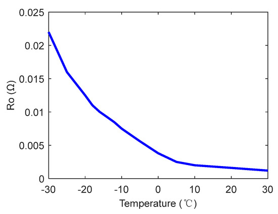
Figure 4.
Ohmic resistance at different temperatures.
Different from the ohmic resistance, the polarization resistance not only relies on temperature, but also exhibits a strong relationship with the SOE. Figure 5 shows the activation polarization resistance and concentration polarization resistance curves with respect to the SOE at −20 °C. It can be observed that as the SOE decreases, R1 and R2 increase gradually, and the latter significantly increase when the SOE approaches 0%.
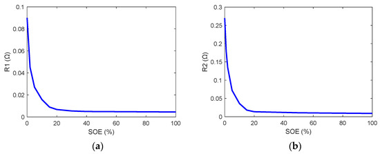
Figure 5.
Polarization resistance at −20 °C. (a) Activation polarization resistance; (b) concentration polarization resistance.
As explained before, in this study, the energy capacity was investigated instead of the ampere-hour capacity. At the end of discharging, the output voltage of the cell dropped to the cut-off voltage which implies that no available energy was left; however, this end to discharging was due to the low output voltage caused by the large resistance instead of the real depletion of the active reaction substance. Therefore, the discharging rate highly affects the available energy capacity. A higher rate results in a lower output voltage and the cut-off voltage being reached earlier. In this study, the discharging rate was chosen to be 0.3 C in the capacity tests to be consistent with average driving conditions. Figure 6 shows the energy capacity of the cell at different temperatures. When the cell temperature is above 23 °C, the available energy capacity almost remains at the highest level. Below 23 °C, the energy capacity shows a monotonic decrease and loses more than 50% of the capacity at −30 °C.
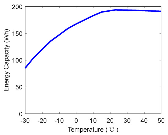
Figure 6.
Cell energy capacity at different temperatures.
The SOE of the battery cell is calculated in the following way. First, the total available cell capacity (Et) is determined by the calibration shown in Figure 6 with known cell temperature. Second, the instantaneous discharging power of the cell is the summation of load power (Pload) the Joule heat generated by the internal resistances of the cell, and the heating power consumed by the external heating system (Pheat). Third, the consumed energy (Ec) is the integral of the instantaneous discharging power over time, as shown in Equation (2).
Finally, cell SOE is calculated by (3):
where SOE0 is the initial state of energy. Note that in the final controller implementation, SOE refers to the state of energy of the entire battery pack, Pload is the load power of the vehicle, and Pheat is the total heating power of the heater; thus, the Joule heat terms in Equation (2) should be multiplied by the cell numbers in a pack. Since the total available cell capacity (Et) is a function of cell temperature, it will be updated in Equation (3) for when the cell temperature changes. This implies the possibility that the SOE increases even if the battery is discharging, when the rising cell temperature brings in the recovery of the cell capacity.
2.3. Thermal Model
The thermal model predicts the instantaneous cell temperature based on thermodynamics and the heat transfer mechanism. The heat generated internally can be modeled by the following equation:
where Q is the total internal heat generated by the cell. The major portion of internal heat is caused by the cell resistance, that is, the Joule heat denoted by Qj. The other part is the entropic heat denoted by Qe, which is relatively small and negligible in the simulation. The heat generated externally comes from the heat transfer between the cell and the electrothermal film, and can be modeled as a heat convection process, as shown in Equation (5):
where Qtr is the total transferred heat, and h1 and h2 are the heat transfer coefficients of the cell to the electrothermal film and of the cell to the air, respectively. A1 and A2 are the area of the film and the area of the cell exposed to air, respectively. The temperature of the cell, the film, and the environmental air are denoted by T, Th and T∞, respectively. Combining internal heat and external heat together, the final thermal model which represents the dynamic behavior of the cell and film temperature can be expressed by Equations (6) and (7):
where m and mh are the mass of the cell and the electrothermal film, respectively. C and Ch are the thermal capacity of the cell and the film, respectively. η is the thermal efficiency of the film. Similarly, Equations (6) and (7) should be modified to describe an entire battery pack in the final controller implementation.
3. Fuzzy Logic External Heating Control
Due to the shrunken available capacity of the battery at low temperatures, the driving range of the vehicle will be greatly reduced compared to that under normal temperature cases. Although the internal resistance will generate Joule heat and the battery will be warmed up by internal heating during driving, this procedure is relatively slow because the internal resistance is small, and the depletion of available energy is faster than the recovery of battery temperature. The main purpose of developing the external heating strategy in this study was to utilize the electrothermal film which has a larger resistance than the cell to heat up the battery in a more efficient way, and to obtain the longest driving range under different conditions.
To achieve this goal, many factors should be considered in the control design. First, the load power of the vehicle affects the total driving duration, and a large load power implies a shorter time for heating; thus, a larger heating power is needed to accelerate the heating process. Second, a lower initial SOE at lower temperature implies lower remaining available energy but higher “hidden” energy; thus, heating up the battery with large power could recover a large amount of available energy. Third, a cold battery needs more heating power and a warm battery needs less heating power, etc. Additionally, the heating power comes from the remaining available energy of the battery which itself reduces the driving range. Hence, there exists an optimal choice of external heating power to deal with the trade-off between the temperature rise rate and consumed heating energy, and to consider all different driving conditions. In this study, a fuzzy logic control (FLC) algorithm was developed to obtain a suboptimal solution and will be illustrated in the following subsections. Compared with the DP algorithm, FLC may not be able to achieve a global optimal solution, but does not require the preknowledge of the cycle information, and can greatly reduce the computational load, which makes it applicable in real-time applications.
3.1. Control Structure
The main approach in the external battery heating controller is that of fuzzy logic control (FLC), and the entire control block diagram is shown in Figure 7. There are three inputs of the control system including load power (Pload), SOE and cell temperature (T). The output of the control system is the heating power (Pheat). The Pload changes from positive (accelerating) to negative (regenerative braking) all the time during a driving cycle, and has the fastest change rate among the three inputs. SOE has a medium change rate, and has an overall trend of depletion with some small fluctuations. The cell temperature is the slowest changing parameter and has a monotonously increasing trend during a driving cycle. Therefore, only the load power and SOE are taken as the inputs of the FLC to reduce the computational load. Fuzzy inference performs within different temperature regions, and the final decision is made through weighted switching between defuzzifying results.

Figure 7.
Block diagram of fuzzy logic control of external battery heating.
The FLC part of the controller has the general structure of a standard FLC, which consists of four blocks: fuzzifier, fuzzy inference, rule base and defuzzifier. The fuzzifier is the fuzzy interface of the input signals which are the load power and cell SOE in this study; it transforms the physical values of input signals into a fuzzy subset consisting of an interval for the range of the input values and an associate membership function describing the degrees of confidence of the input belonging to this range, specifically, linguistic values. The rule base contains the fuzzy control logic, specifically a set of IF-THEN rules which are made by domain experts and experiences. In this study, the rule base contains three rules with respect to the three different temperature regions. The fuzzy inference block makes the inference based on the rules. The defuzzifier converts the linguistic results which are obtained from the fuzzy inference back to exact control values, and in this study, the three heating powers are the outputs of the defuzzifier. After the FLC block, the weighted summer block fuses the three heating powers together to obtain the final heating power, and the details will be illustrated in the following subsection.
3.2. Fuzzy Logic Control Design
3.2.1. Membership Functions
The membership functions of the inputs and outputs are shown in Figure 8.
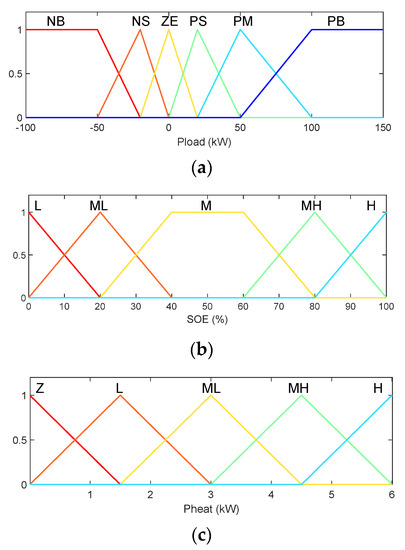
Figure 8.
Membership functions of input and output variables. (a) Input variable (Pload); (b) input variable (SOE); (c) output variable (Pheat).
The two input variables are the load power of the vehicle (Pload) and the SOE of the battery pack. The range of the input variable Pload is between −50 kW and 100 kW, which can cover most of the normal driving conditions of the vehicle. The Pload consists of six membership functions: NB, NS, ZE, PS, PM, and PB, which represent strong regenerative braking, mild regenerative braking, zero power, mild acceleration, and strong acceleration cases, respectively. The range of the input variable SOE is from 0% to 100%, and it consists of five membership functions: L, ML, M, MH, and H, which represent low, medium low, medium, medium high, and high SOEs, respectively.
The single output variable is the heating power of the entire heater, and the operating range is between 0 kW and 6 kW. The Pheat consists of five membership functions: Z, L, ML, MH, and H, which represent non-heating, low power heating, medium low power heating, medium high power heating, and high power heating cases, respectively.
3.2.2. Fuzzy Control Rules
There are three rules in the rule base with respect to the three different temperature regions. The control rules were obtained by the knowledge and intuition of the battery electrothermal system, and the experience of external battery heating experiments with the test bench described in Section 4.1, and test procedures described in Section 4.2. Different levels of heating power were performed at each cell temperature and initial SOE to search for the optimal heating power. Then, the optimal power along with the corresponding temperature and SOE were converted into linguistic language to form the fuzzy rules. Table 3 shows the rule in a low temperature region.

Table 3.
Fuzzy rule for the low temperature condition.
From the perspective of load power, when it is NB (which represents strong regenerative braking), the heating power is H. The main reason is that at extremely cold temperatures, the charge capability of the cell is highly limited; in this case, the large amount of unabsorbable regenerative power can be utilized to heat the battery. When the load power increases from zero to positive, the heating power should also increase to warm up the battery faster since it will be easier for the SOE to drop to the bottom at a higher load.
From the perspective of the SOE, a larger heating power is required at a lower SOE, especially when the load power is PM and PB, and when the SOE is ML and L. As explained in the previous section, the end of discharging (in other words, 0% SOE) does not mean there are no existing lithium ions for chemical reaction; it only implies that the output voltage of the cell drops to the cut-off voltage because of the large resistance at low temperatures. Therefore, with higher discharging power, the output voltage will drop to the cut-off voltage even earlier, and in this case, it is urgent to recover the “unavailable” capacity by increasing the cell temperature; thus, high heating power is applied. It should be noted that since large power from the battery is used for heating, the load power requirement may not be fully satisfied in high acceleration cases, and the vehicle performance may be degraded. This is a trade-off; however, discharging performance should be limited in low-temperature low-SOE cases even without battery heating for the safety consideration.
Table 4 shows the rule in the medium temperature region. The overall heating power is lower compared with the rule in the low temperature region. The main reason is that when the battery is warmer, the unavailable capacity is smaller, and therefore the lower heating power is needed to fully recover the battery capacity by the end of the driving cycle. Particularly, when the SOE is H and the load power is not PB, there is no need to perform external heating, since there will be a sufficiently long time to heat up the battery by internal resistance heating.

Table 4.
Fuzzy rule for the medium temperature condition.
Table 5 shows the rule in the high temperature region. In most cases, the external heating power is zero since internal resistance heating is adequate for warming up the battery. When the load power is NB, since the charging capability of the cell also recovers at warmer temperatures, more regenerative braking power goes to the battery, and the heating power drops to L.

Table 5.
Fuzzy rule for the high temperature condition.
3.2.3. Defuzzification
The center-of-gravity (COG) method is used for defuzzification, and three output variables will be obtained at the same time, namely Ph1, Ph2 and Ph3, which refer to the heating power at low, medium and high temperature regions, respectively. These three output variables will be merged into the final heating power in the weighted switching block.
3.3. Weighted Switching
One simple approach to obtain the final heating power was to make a hard switch between the three temperature regions. That is, to define a specific range of each temperature region, and choose either Ph1, Ph2 or Ph3 based on which range the actual cell temperature is located in. However, this hard switch could not provide the optimal control result. Since the cell temperature increased gradually, the final heating power was obtained by summing Ph1, Ph2 and Ph3 with the respective weightings to achieve smooth switching. As shown in Figure 9, w1, w2 and w3 are the weightings for Ph1, Ph2 and Ph3, respectively. The final heating power was calculated by Equation (8).
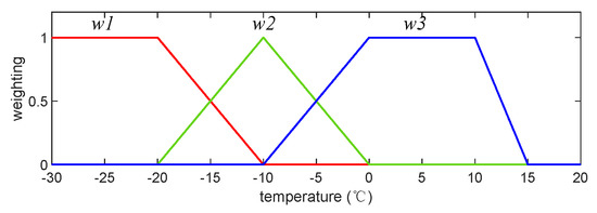
Figure 9.
Weightings of the output variables of FLC in the three different temperature regions.
For example, when the cell temperature was −13 °C, the weightings were w1 = 0.3, w2 = 0.7, w3 = 0, as seen from Figure 8; thus, Pheat = 0.3Ph1 + 0.7Ph2. Since the shape of the weighting functions looks similar to the membership function, we can also name this function “fuzzy switching”. Note that the cell available capacity almost reaches the nominal capacity when the cell temperature is above 15 °C, and no necessary external heating is required; thus, all weightings drop to zero in this range.
4. Results and Discussions
4.1. Test Setup
The experimental platform is shown in Figure 10. The battery module that was tested was formed by eight cells, which is shown in Figure 1c. A battery testing system with a maximum voltage of 20 V operated in power mode to charge and discharge the battery. The testing system integrates a data acquisition function which captures the voltage and temperature of the cells, and the data was recorded on a host computer. The battery module was soaked in a temperature chamber to maintain the desired cell temperature. The external heater was powered by a DC power supply instead of the battery module for the convenience of the tests.
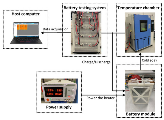
Figure 10.
Experimental platform of battery external heating system.
4.2. Experimental Results
First, real-world road tests were performed at different low temperatures to validate the equivalent circuit model. These tests started with different initial SOEs and covered different driving conditions, and the data were compared with the simulation on the proposed model. Note that the different initial conditions were obtained by driving the fully charged car at a normal temperature for a certain distance followed by an overnight cold soak. Figure 11 shows a test case with the initial condition of 52% SOE and a temperature of −28 °C. The driving cycle lasted for 2800 s, covering mild driving, aggressive acceleration, hard braking, repeated tip-in-tip-out driving actions, etc. It can be seen that the simulation result matches the experimental data very well, which validates the reliability of this model with well-calibrated parameters. The other comparison results are not shown here due to the limited space.
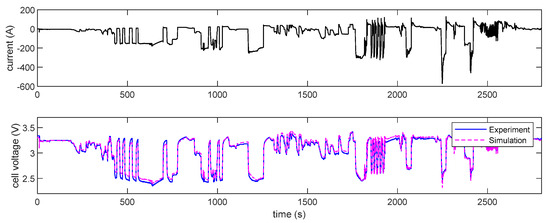
Figure 11.
Real-world driving data validation.
Second, external heating tests with the test configuration shown in Figure 10 were performed to validate the thermal model. The target module was soaked in the temperature chamber as the testing object. The heater operated at a constant power, and the cells were discharged by the battery testing system at a constant current. The tests started from different initial conditions with different discharging currents and heating powers. All the tests stopped when the SOE reached zero. Simulations with the same battery module setting were run under the same operating conditions for comparison. Two typical test results are shown below. The first test started with a cell temperature of −20 °C and an initial SOE of 30%; the cell discharging current was 5 A, and the heating power on each cell was 1 W. A comparison between experiment and simulation is shown in Figure 12a. The second test started with a cell temperature of −10 °C and an initial SOE of 100%; the cell discharging current was 10 A, and the heating power on each cell was 2 W. A comparison between the experiment and simulation is shown in Figure 12b. From the comparisons, it can be seen that the temperature estimation error was always less than 1 °C.
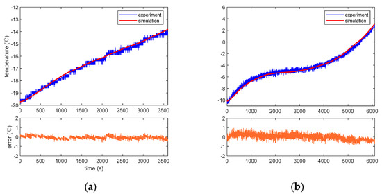
Figure 12.
External heating tests at constant discharging current and constant heating power. (a) Initial cell temperature of −30 °C, initial SOE of 30%, cell discharging current of 5 A and a heating power on each cell of 1 W; (b) initial cell temperature of −10 °C, initial SOE of 100%, cell discharging current of 10 A and a heating power on each cell of 2 W.
Based on the experimental validation, the validity of the proposed model has been proven from the aspects of electrical and thermal behavior of the battery. Therefore, in the following section, the proposed model will be used to replace the real battery in the simulation and to validate the fuzzy logic control strategy for external battery heating.
4.3. Simulation Results
The proposed fuzzy logic control strategy was evaluated by simulation, including simple cases such as a constant load power case and complicated cases such as those involving standard driving cycles.
The first group of simulations evaluated the cell energy recovery under a constant load power with and without external heating. A maximum power heating strategy was simulated for comparison in which the heating power remained constant at 6 kW (the maximum power of the heater of the entire pack). In Figure 13a, the first test case started with 30% initial SOE and a −30 °C initial cell temperature, and ended up with 0% SOE; the constant load power was 50 W for each cell. It can be seen that external heating significantly increased the cell’s available energy capacity. Without heating, the cell only provided 23.2 Wh of energy, and the final cell temperature was −28.6 °C. With maximum power heating, the cell provided 112.25 Wh of energy, and the final cell temperature was 10.9 °C; 42.17 Wh of energy was used for heating, and 70.08 Wh of energy was the “useful” amount of energy which could be used for propelling the vehicle. With the proposed FLC strategy, the cell provided 109.93 Wh of energy, and the final cell temperature was 9.1 °C; 39.65 Wh of energy was used for heating, and 70.28 Wh of energy was used for propulsion. The energy recovery between the maximum power strategy and FLC strategy is comparable since this was a low-temperature and low-SOE case, and based on the fuzzy rules, the heating power was high most of the time.
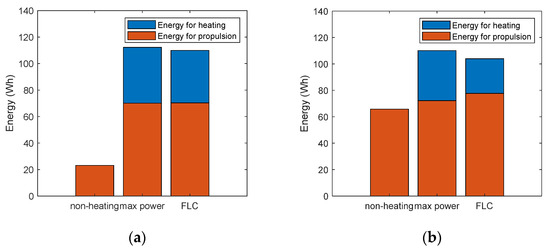
Figure 13.
External heating tests at constant load power. (a) Initial cell temperature of −30 °C, initial SOE of 30%, and cell discharging power of 50 W; (b) initial cell temperature of −10 °C, initial SOE of 50%, and cell discharging power of 30 W.
In Figure 13b, the second test case started with a 50% initial SOE and a −10 °C initial cell temperature; the constant load power was 30 W for each cell. The result is different from the first case. Without external heating, the cell provided 65.7 Wh of energy, and the final cell temperature was −9.1 °C. The maximum power heating strategy gained a 19.4 °C final temperature and 110.03 Wh of total available energy, which are higher than the values of 13.8 °C and 103.87 Wh obtained under FLC strategy. However, with the maximum power heating strategy, the cell extracted too much energy for heating (37.88 Wh), which greatly reduced the amount of “useful” energy for propulsion (72.15 Wh). In contrast, the FLC strategy considered the trade-off between total capacity recovery and consumed heating energy, and thus gained more energy for vehicle propulsion (77.63 Wh).
The second group of simulations validated the battery heating strategy during driving. To evaluate the benefits of the proposed FLC of the external battery heating strategy under different driving conditions, EPA driving cycles were applied in the simulations. The load powers of the driving cycles were collected from real vehicle driving data in a bench test; the SOE and temperature signals were generated by the developed electrical and thermal battery model during the simulation.
EPA driving cycles include three typical and commonly used cycles, which are UDDS, HWFET and US06 cycles. In the first test case, the initial battery SOE was set to 30% and the initial temperature was set to −30 °C. This was an extremely cold case with low initial available energy. In order to show the benefit of the proposed control strategy, other strategies were tested for comparison, including driving without heating, maximum power heating, and optimal heating based on DP. Figure 14 shows the driving range comparison between each strategy. From the result, first, it can be seen that external battery heating can significantly increase the driving range in this case (from 45.9% to 150.4%). The main reason is that in extremely cold conditions, a large portion of the energy is not available for use; however, this amount of “hidden” energy can be “released” by heating up the battery. Furthermore, the UDDS cycle has the lowest load power, which makes the internal battery heating slow, hence it achieves the shortest range if used without external heating. Second, the FLC heating strategy achieved a longer range than the maximum power heating strategy did, achieving a range of around 4.2% to 5.3%. Third, the achieved ranges are very close between the FLC heating strategy and DP strategy, which implies that the proposed FLC heating strategy can almost achieve an optimal control result.
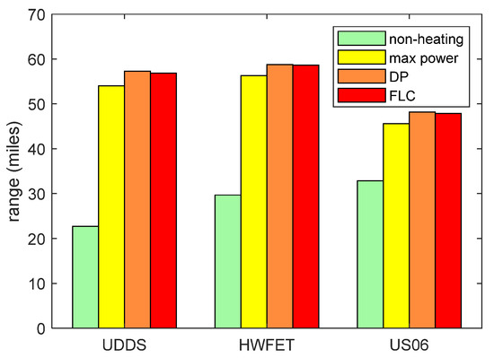
Figure 14.
EPA driving cycle tests with initial cell temperature of −30 °C and initial SOE of 30%.
In the second test case, the initial battery SOE was set to 100% and the initial temperature was set to −10 °C. This was a medium cold case with high initially available energy. As shown in Figure 15, in the UDDS and HWFET cycles, maximum power heating did not help increase the range too much compared with non-heating, which implies that most of the recovered energy was used for external heating. The FLC strategy still shows obvious improvement (around 3.6% to 4.6%) in the driving range compared to the maximum power strategy, and achieves only 0.3% to 1% less range than global optimal results do by using the DP algorithm; moreover, a 5.8% to 34.1% improvement was achieved compared to the non-heating configuration.
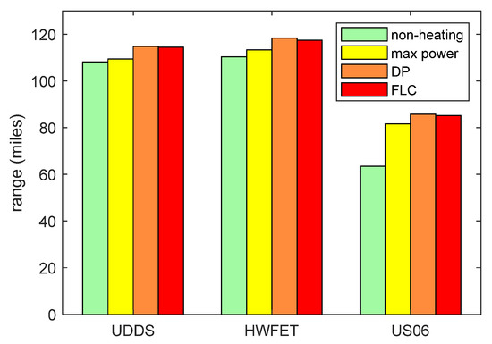
Figure 15.
EPA driving cycle tests with an initial cell temperature of −10 °C and initial SOE of 100%.
5. Conclusions
An external battery heating system was developed in this study to solve the driving range reduction issue at low temperatures for electric vehicles. An electrothermal film with polyimide material was attached to the cell surface, and the film was powered by the battery to generate heat and warm up the battery during driving. The fuzzy logic control (FLC) algorithm was utilized to optimize the heating power considering different operating conditions, including the battery SOE, temperature and driving load power. A mathematical model which describes the electrical and thermal characteristics of the system was used to validate the proposed control strategy by simulation. The constant maximum power heating strategy and global optimal control strategy obtained by dynamic programming were used for comparison. The simulation results show that the proposed control strategy can significantly increase the driving range at low temperatures. Compared with the non-heating configuration, the proposed FLC strategy shows an increase of 5.8% to 150.4% in the total driving range under different driving conditions. Compared with the maximum power heating strategy, the FLC strategy improves the driving range by 3.6% to 5.3%. Besides, the FLC strategy has a performance that is close to the global optimum, but has relatively much lower computational requirements and is thus suitable for onboard implementation.
Author Contributions
Conceptualization, S.Z. and L.C.; methodology, S.Z.; modeling and simulation, S.Z., L.C. and T.L.; experimental validation, T.L.; writing—original draft preparation, S.Z.; writing—review and editing, L.C. All authors have read and agreed to the published version of the manuscript.
Funding
This research was supported by the project “Modeling and Control of New Energy Vehicle Powertrain Systems” funded by Shenzhen Technology University with grant number 2018010801007.
Data Availability Statement
Simulation and experimental data which do not reflect confidential information about the target cell and vehicle are available from the corresponding author upon reasonable request.
Acknowledgments
We would like to thank our lab technicians and students who supported the experiments related to this paper.
Conflicts of Interest
The authors declare no conflict of interest.
References
- Yong, J.Y.; Ramachandaramurthy, V.K.; Tan, K.M.; Mithulananthan, N. A review on the state-of-the-art technologies of electric vehicle, its impacts and prospects. Renew. Sustain. Energy Rev. 2015, 49, 365–385. [Google Scholar] [CrossRef]
- Wilberforce, T.; El-Hassan, Z.; Khatib, F.N.; Makky, A.A.; Baroutaji, A.; Carton, J.G.; Olabi, A.G. Developments of electric cars and fuel cell hydrogen electric cars. Int. J. Hydrogen Energy 2017, 42, 25695–25734. [Google Scholar] [CrossRef]
- Capasso, C.; Veneri, O. Experimental analysis on the performance of lithium based batteries for road full electric and hybrid vehicles. Appl. Energy 2014, 136, 921–930. [Google Scholar] [CrossRef]
- Jaguemont, J.; Boulon, L.; Dubé, Y. A comprehensive review of lithium-ion batteries used in hybrid and electric vehicles at cold temperatures. Appl. Energy 2016, 164, 99–114. [Google Scholar] [CrossRef]
- Meyer, N.; Whittal, I.; Christenson, M.; Loiselle-Lapointe, A. The Impact of Driving Cycle and Climate on Electrical Consumption & Range of Fully Electric Passenger Vehicles. In Proceedings of the EVS26 International Battery, Hybrid and Fuel Cell Electric Vehicle Symposium, Los Angeles, CA, USA, 6–9 May 2012. [Google Scholar]
- Reyes, J.R.M.D.; Parsons, R.V.; Hoemsen, R. Winter Happens: The Effect of Ambient Temperature on the Travel Range of Electric Vehicles. IEEE Trans. Veh. Technol. 2016, 65, 4016–4022. [Google Scholar] [CrossRef]
- Smart, M.C.; Ratnakumar, B.V.; Behar, A.; Whitcanack, L.D.; Yu, J.S.; Alamgir, M. Gel polymer electrolyte lithium-ion cells with improved low temperature performance. J. Power Sources 2007, 165, 535–543. [Google Scholar] [CrossRef]
- Senyshyn, A.; Mühlbauer, M.J.; Dolotko, O.; Ehrenberg, H. Low-temperature performance of Li-ion batteries: The behavior of lithiated graphite. J. Power Sources 2015, 282, 235–240. [Google Scholar] [CrossRef]
- Liu, K.; Kang, L.I.; Peng, Q.; Zhang, C. A brief review on key technologies in the battery management system of electric vehicles. Front. Mech. Eng. 2018, 14, 47–64. [Google Scholar] [CrossRef]
- Wu, S.; Xiong, R.; Li, H.; Nian, V.; Ma, S. The state of the art on preheating lithium-ion batteries in cold weather. J. Energy Storage 2020, 27, 101059.1–101059.13. [Google Scholar] [CrossRef]
- Ji, Y.; Wang, C. Heating strategies for Li-ion batteries operated from subzero temperatures. Electrochim. Acta 2013, 107, 664–674. [Google Scholar] [CrossRef]
- Song, Z.; Hofmann, H.; Li, J.; Hou, J.; Zhang, X.; Ouyang, M. The optimization of a hybrid energy storage system at subzero temperatures: Energy management strategy design and battery heating requirement analysis. Appl. Energy 2015, 159, 576–588. [Google Scholar] [CrossRef]
- Li, G.; Huang, X.; Fu, X. Design Research on Battery Heating and Preservation System Based on Liquid Cooling Mode. J. Hunan Univ. 2017, 44, 26–33. [Google Scholar]
- Zhang, J.; Sun, F.; Wang, Z. Heating character of a LiMn2O4 battery pack at low temperature based on PTC and metallic resistance material. Energy Procedia 2017, 105, 2131–2138. [Google Scholar] [CrossRef]
- Su, Z.A. Lithium Ion Power Battery Heating Device. China Patent CN101710630A, 10 August 2011. [Google Scholar]
- Lei, Z.; Zhang, C.; Li, J.; Fan, G.; Lin, Z. Preheating method of lithium-ion batteries in an electric vehicle. J. Mod. Power Syst. Clean Energy 2015, 3, 289–296. [Google Scholar] [CrossRef]
- Zhang, Z.; Li, Q.; Zhang, Z.; Hua, Y. Pre-Heating Simulation of Lithium-ion Battery Module for Electric Vehicles. J. Comput. Simul. 2021, 5, 85–89. [Google Scholar]
- Hu, X.; Zheng, Y.; Howey, D.A.; Perez, H.E.; Pecht, M. Battery warm-up methodologies at subzero temperatures for automotive applications: Recent advances and perspectives. Prog. Energy Combust. Sci. 2020, 77, 100806. [Google Scholar] [CrossRef]
- Alaoui, C.; Salameh, Z.M. A novel thermal management for electric and hybrid vehicles. IEEE Trans. Veh. Technol. 2005, 54, 468–476. [Google Scholar] [CrossRef]
- Chen, M.; Li, J. Experimental study on heating performance of pure electric vehicle power battery under low temperature environment. Int. J. Heat Mass Transf. 2021, 172, 121191. [Google Scholar] [CrossRef]
- Wang, F.; Zhang, J.; Wang, L. Design of electric air-heated box for batteries in electric vehicles. Chin. J. Power Sources 2013, 37, 1184–1187. [Google Scholar]
- Jin, X.; Li, J.Q.; Zhang, C.N.; Wu, P.E. Researches on Modeling and experiment of liionbattery ptc self-heating in electric vehicles. Energy Procedia 2016, 104, 62–67. [Google Scholar] [CrossRef]
- Qu, Z.G.; Jiang, Z.Y.; Wang, Q. Experimental study on pulse self-heating of lithium-ion battery at low temperature. Int. J. Heat Mass Transf. 2019, 135, 696–705. [Google Scholar] [CrossRef]
- Guo, S.; Xiong, R.; Wang, K.; Sun, F. A novel echelon internal heating strategy of cold batteries for all-climate electric vehicles application. Appl. Energy 2018, 219, 256–263. [Google Scholar] [CrossRef]
- Ruan, H.; Jiang, J.; Sun, B.; Su, X.; He, X.; Zhao, K. An optimal internal-heating strategy for lithium-ion batteries at low temperature considering both heating time and lifetime reduction. Appl. Energy 2019, 256, 113797. [Google Scholar] [CrossRef]
- Gang, N.; Haran, B.; Popov, B.N. Capacity fade study of lithium-ion batteries cycled at high discharge rates. J. Power Sources 2003, 117, 160–169. [Google Scholar]
- Qin, Y.; Du, J.; Lu, L.; Gao, M.; Ouyang, M. A rapid lithium-ion battery heating method based on bidirectional pulsed current: Heating effect and impact on battery life. Appl. Energy 2020, 280, 115957. [Google Scholar] [CrossRef]
- Lin, C.; Kong, W.; Tian, Y.; Wang, W.; Zhao, M. Heating lithium-ion batteries at low temperatures for onboard applications: Recent progress, challenges and prospects. Automot. Innov. 2022, 5, 3–17. [Google Scholar] [CrossRef]
- Bao, S.; Sun, P.; Zhu, J.; Ji, Q.; Liu, J. Improved multi-dimensional dynamic programming energy management strategy for a vehicle power-split hybrid powertrain. Energy 2022, 256, 124682. [Google Scholar] [CrossRef]
- Wang, X.; Hua, Q.; Liu, P.; Sun, L. Stochastic dynamic programming based optimal energy scheduling for a hybrid fuel cell/PV/battery system under uncertainty. Process Saf. Environ. Prot. 2022, 165, 380–386. [Google Scholar] [CrossRef]
- Du, J.; Chen, Z.; Li, F. Multi-objective optimization discharge method for heating lithium-ion battery at low temperatures. IEEE Access 2018, 6, 44036–44049. [Google Scholar] [CrossRef]
- Antonio, G.; Nagano, M.S.; Rolim, G.A. Dynamic programming algorithms and their applications in machine scheduling: A review. Expert Syst. Appl. 2022, 190, 116180. [Google Scholar]
- Chen, J.; Xu, C.; Wu, C.; Xu, W. Adaptive Fuzzy Logic Control of Fuel-Cell-Battery Hybrid Systems for Electric Vehicles. IEEE Trans. Ind. Inform. 2018, 14, 292–300. [Google Scholar] [CrossRef]
- Faisal, M.; Hannan, M.A.; Ker, P.J.; Lipu, M.S.H.; Uddin, M. Fuzzy Based Charging-Discharging Controller for Lithium-ion Battery in Microgrid Applications. IEEE Trans. Ind. Appl. 2021, 57, 4187–4195. [Google Scholar] [CrossRef]
- Chen, G.; Pham, A. Introduction to Fuzzy Sets, Fuzzy Logic, and Fuzzy Control Systems; CRC Press: Boca Raton, FL, USA, 2001. [Google Scholar]
- Zhao, Z. Improved fuzzy logic control-based energy management strategy for hybrid power system of fc/pv/battery/sc on tourist ship. Int. J. Hydrogen Energy 2022, 47, 9719–9734. [Google Scholar] [CrossRef]
Disclaimer/Publisher’s Note: The statements, opinions and data contained in all publications are solely those of the individual author(s) and contributor(s) and not of MDPI and/or the editor(s). MDPI and/or the editor(s) disclaim responsibility for any injury to people or property resulting from any ideas, methods, instructions or products referred to in the content. |
© 2023 by the authors. Licensee MDPI, Basel, Switzerland. This article is an open access article distributed under the terms and conditions of the Creative Commons Attribution (CC BY) license (https://creativecommons.org/licenses/by/4.0/).
