
State-Feedback Control of Interleaved Buck–Boost DC–DC Power Converter with Continuous Input Current for Fuel Cell Energy Sources: Theoretical Design and Experimental Validation


 ,
,  ,
, 
 and
and
Abstract
1. Introduction
2. Modelling and Analysis of Fuel-Cell in Association with Buck–Boost Converter
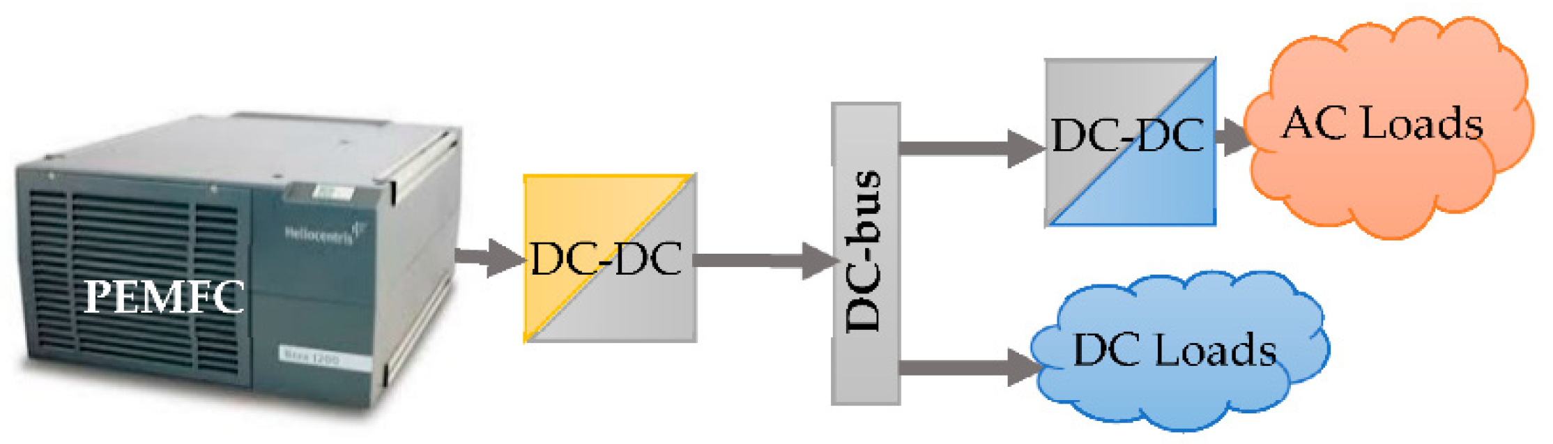
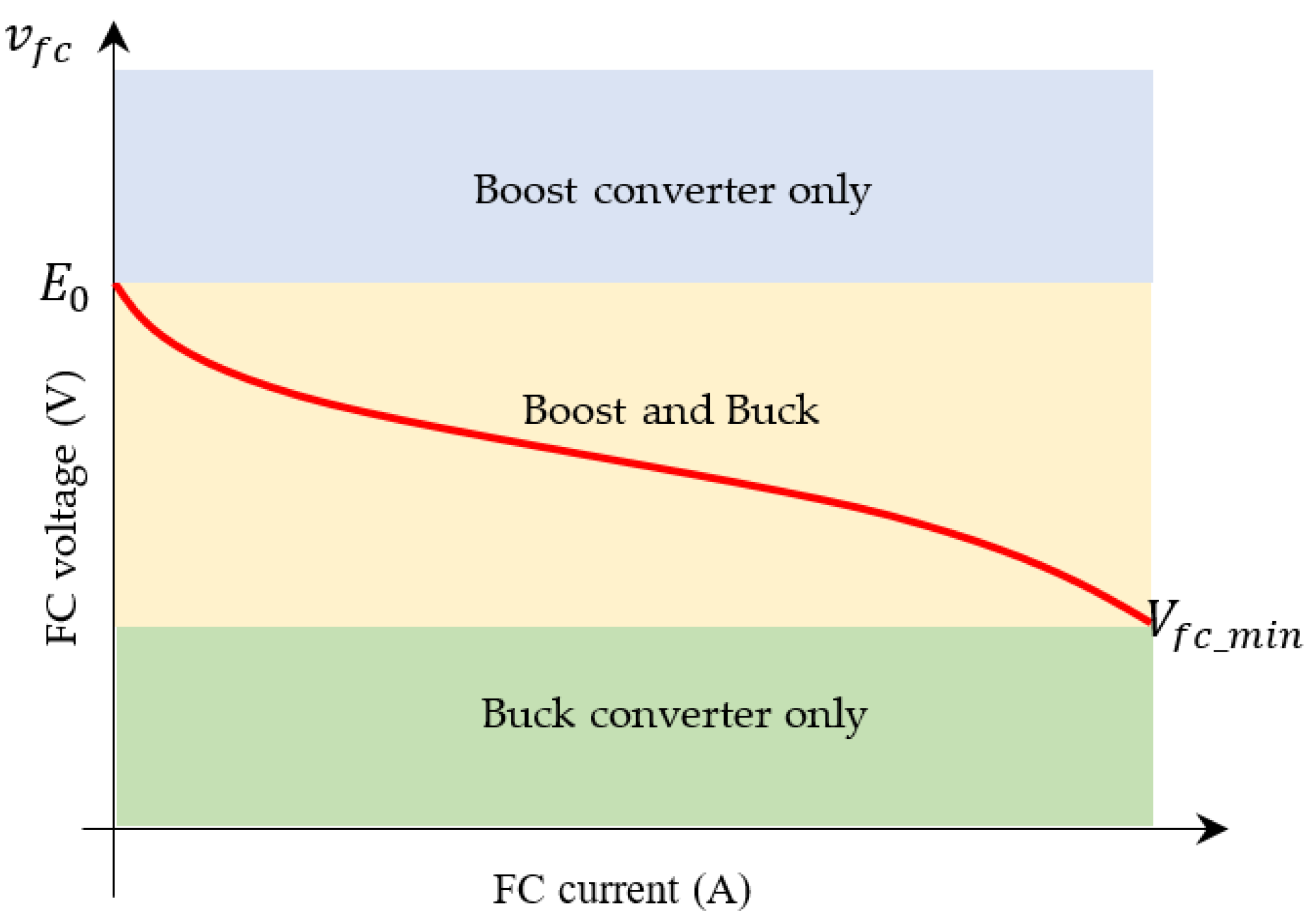
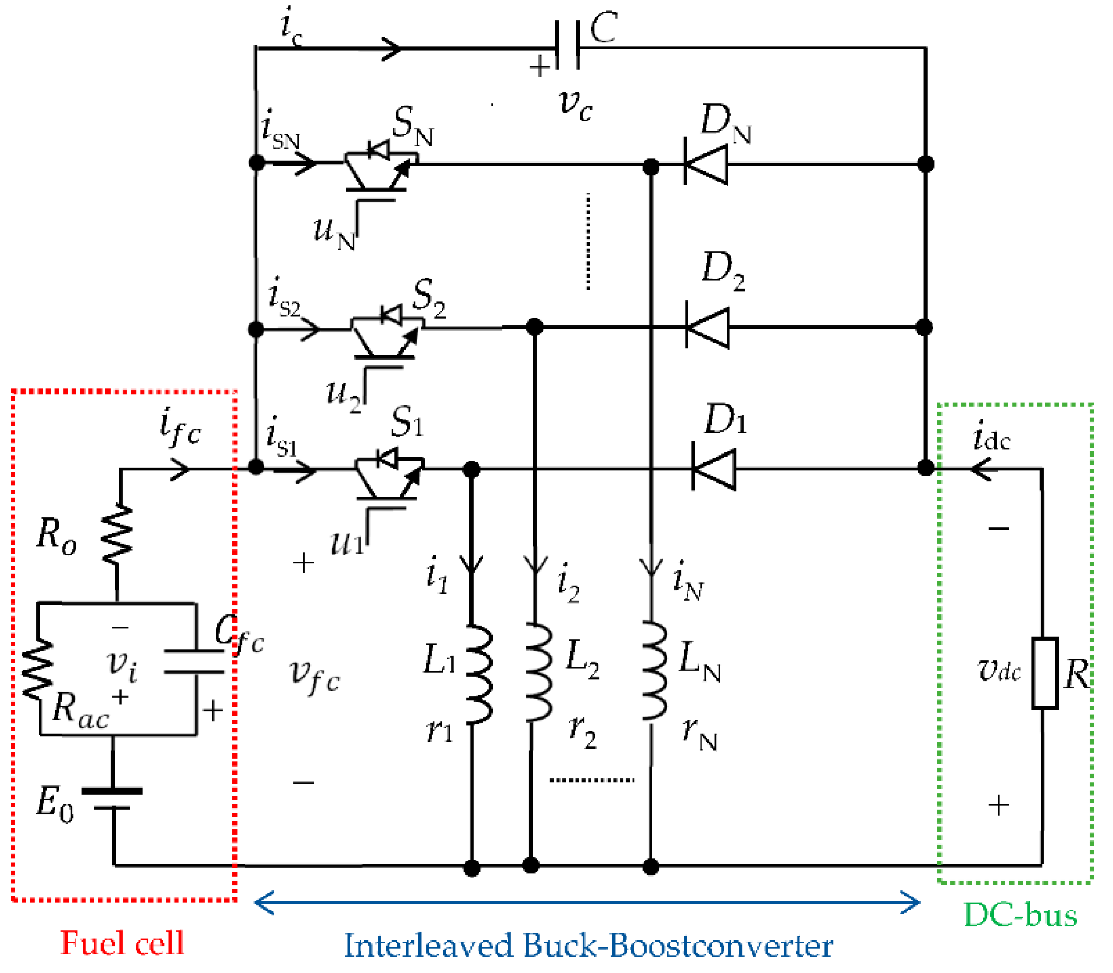
2.1. System Presentation
2.2. System Modelling
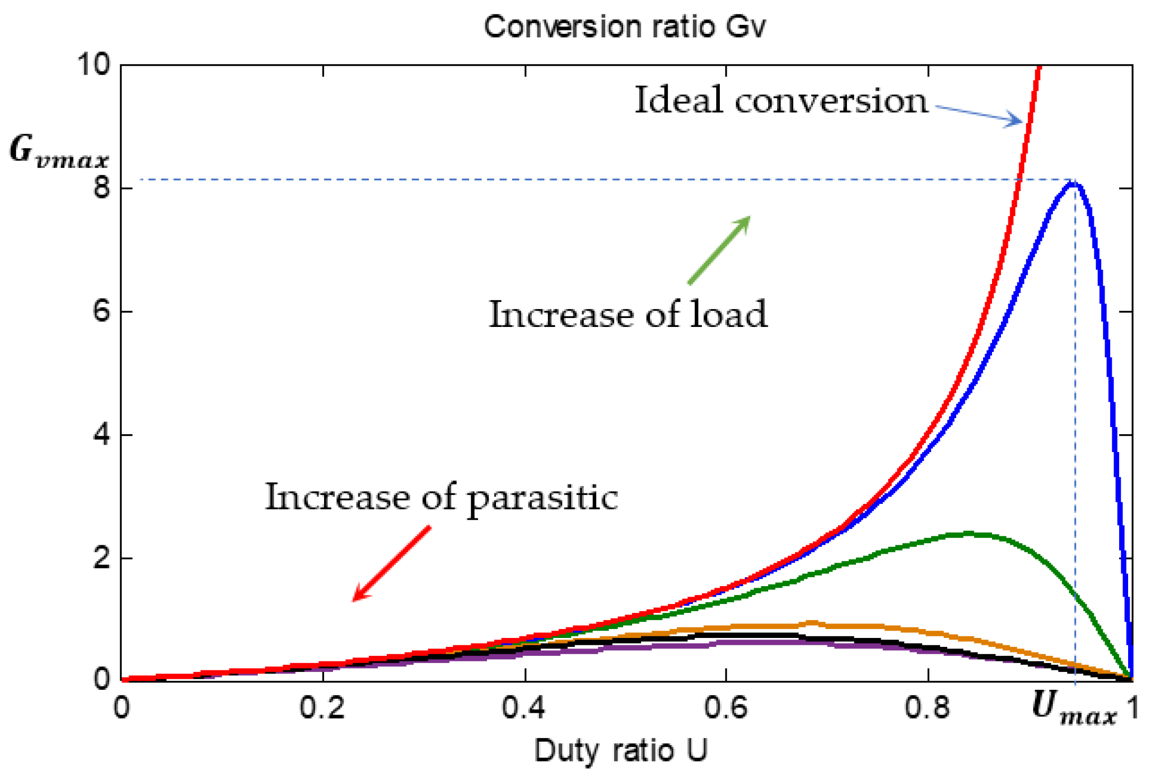
2.3. System Steady State Analysis
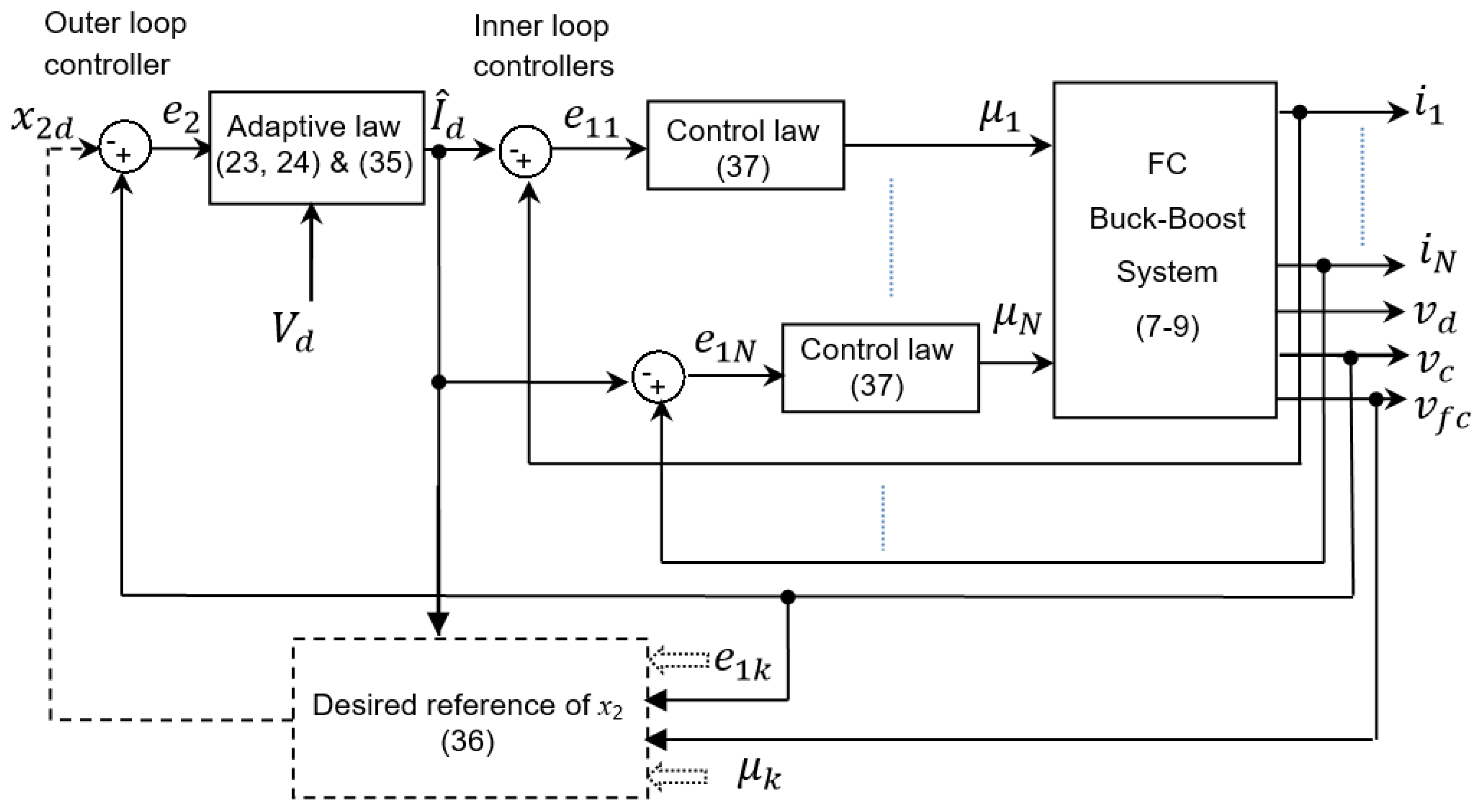
3. Nonlinear State Feedback Controller
- (i)
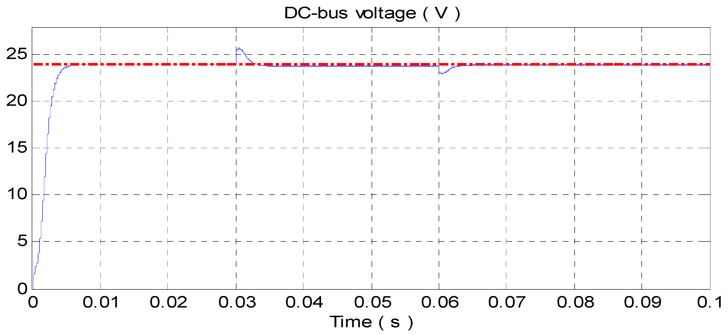
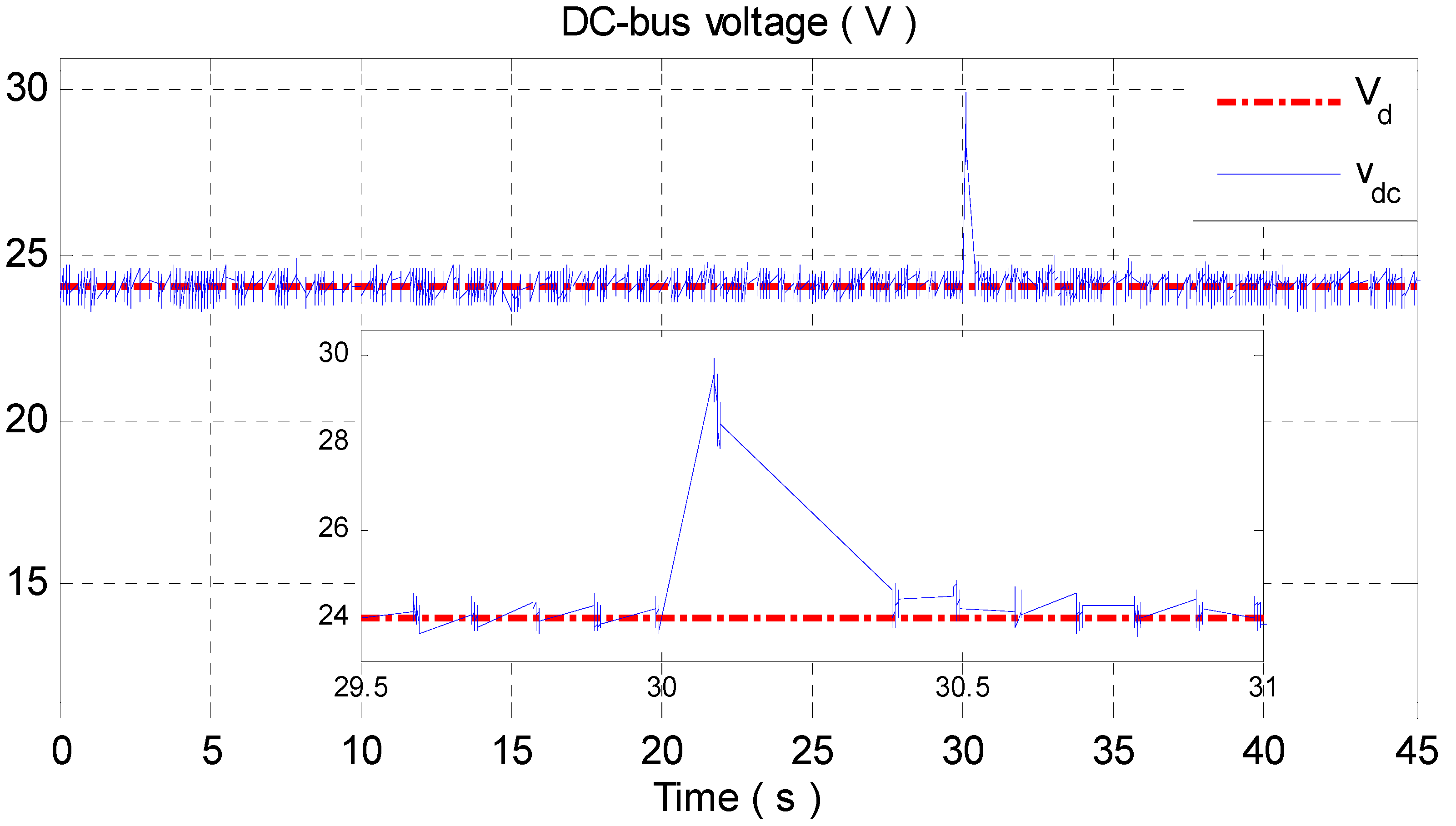
- Tight regulation of output DC-bus voltage despite load uncertainty.
- (ii)
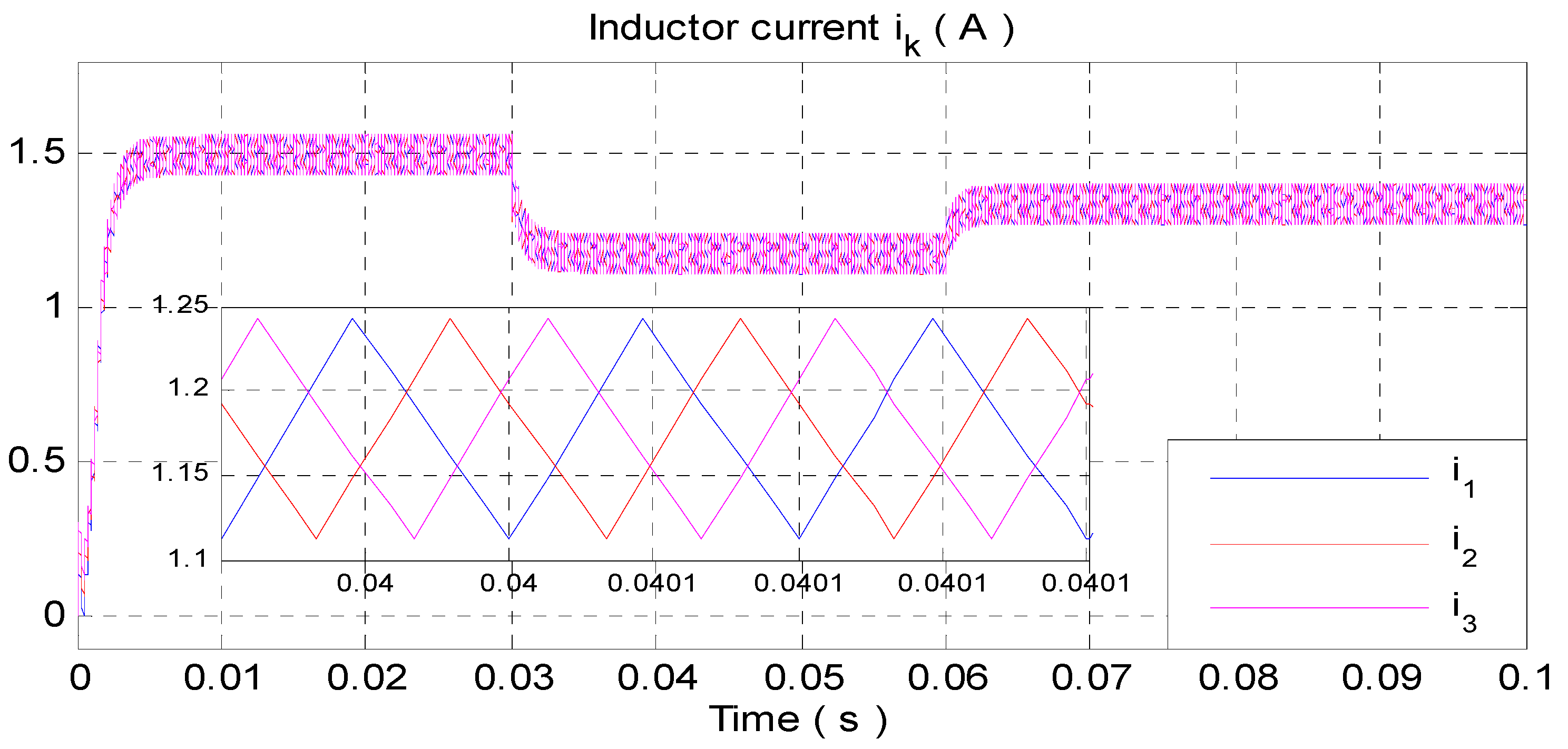
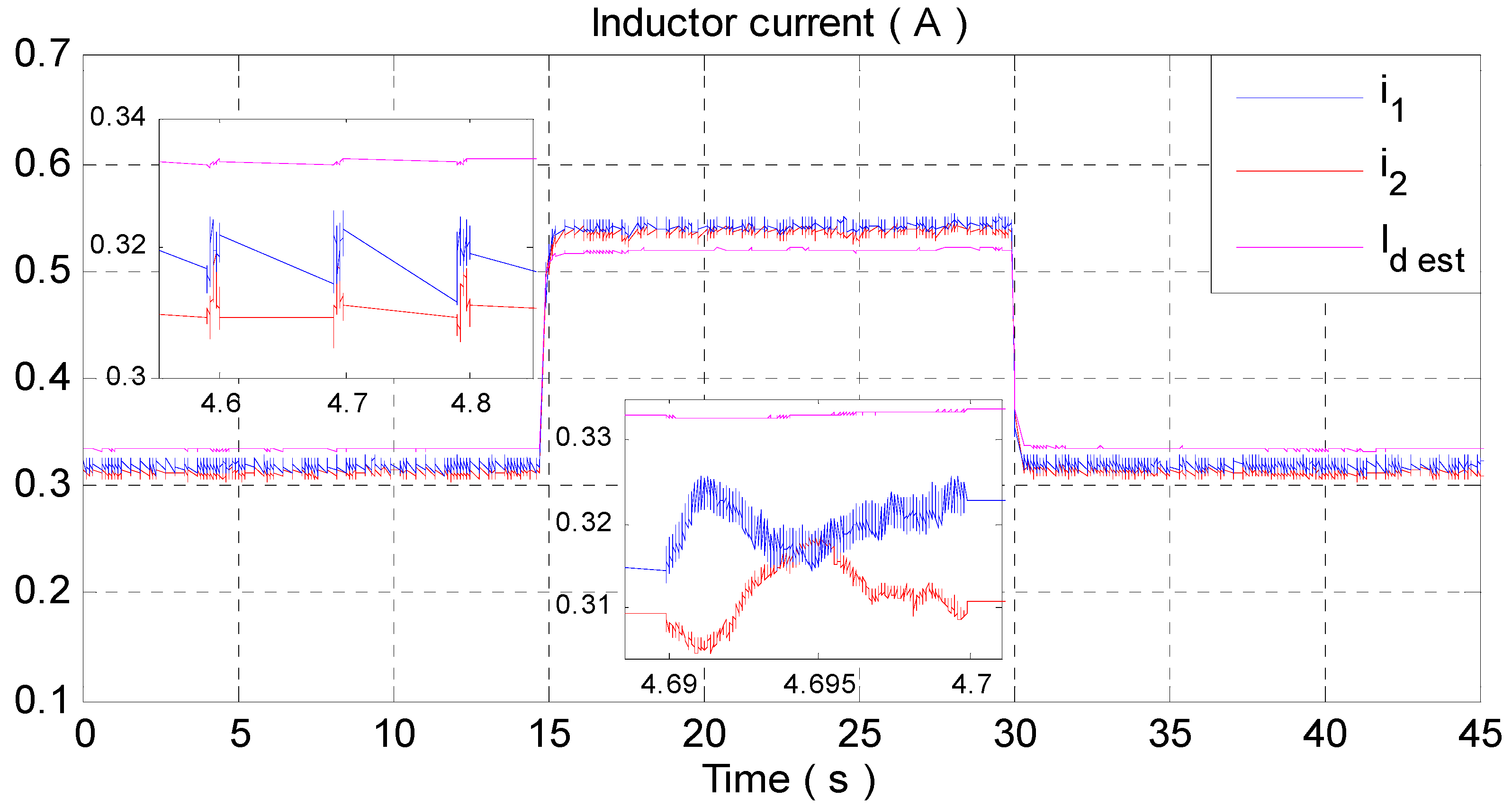
- Equal current sharing between IBBC branches, i.e., the inductor currents should be equal to each other in order to avoid overloading one of the modules, especially when supplying heavy loads. This property entails the reduction in the current ripple, which is beneficial for fuel cells.
- (iii)
- Asymptotic stability of the closed-loop system.
- (1)
- The closed-loop system with state variablesis globally asymptotically stable around the origin;
- (2)
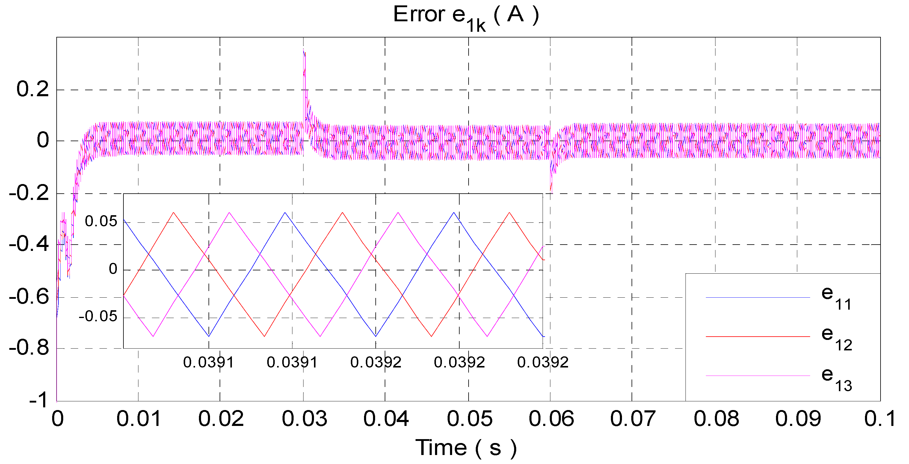
- The tracking errorsconverge asymptotically to zero, implying proper current sharing between the modules;
- (3)
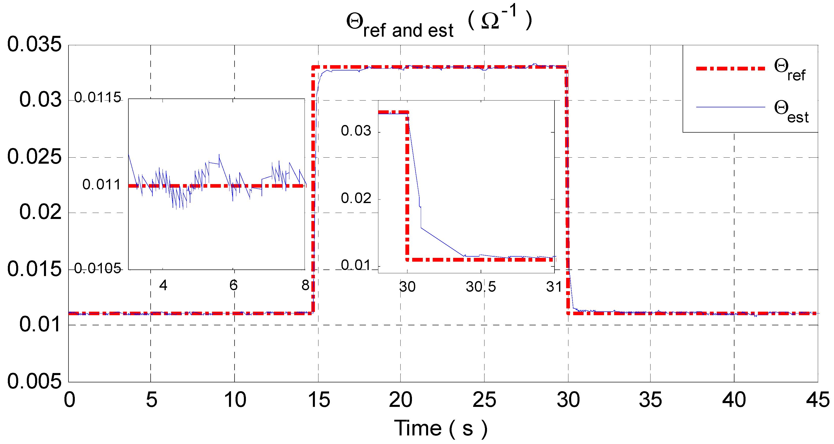
- The estimation errorconverges to zero and, consequently, the estimated reference currentconverges to its real value,. It turns out that the tracking errorconverges to zero, ensuring tight regulation of the DC-bus voltage.
4. Simulation and Experimental Results
4.1. Simulation Results
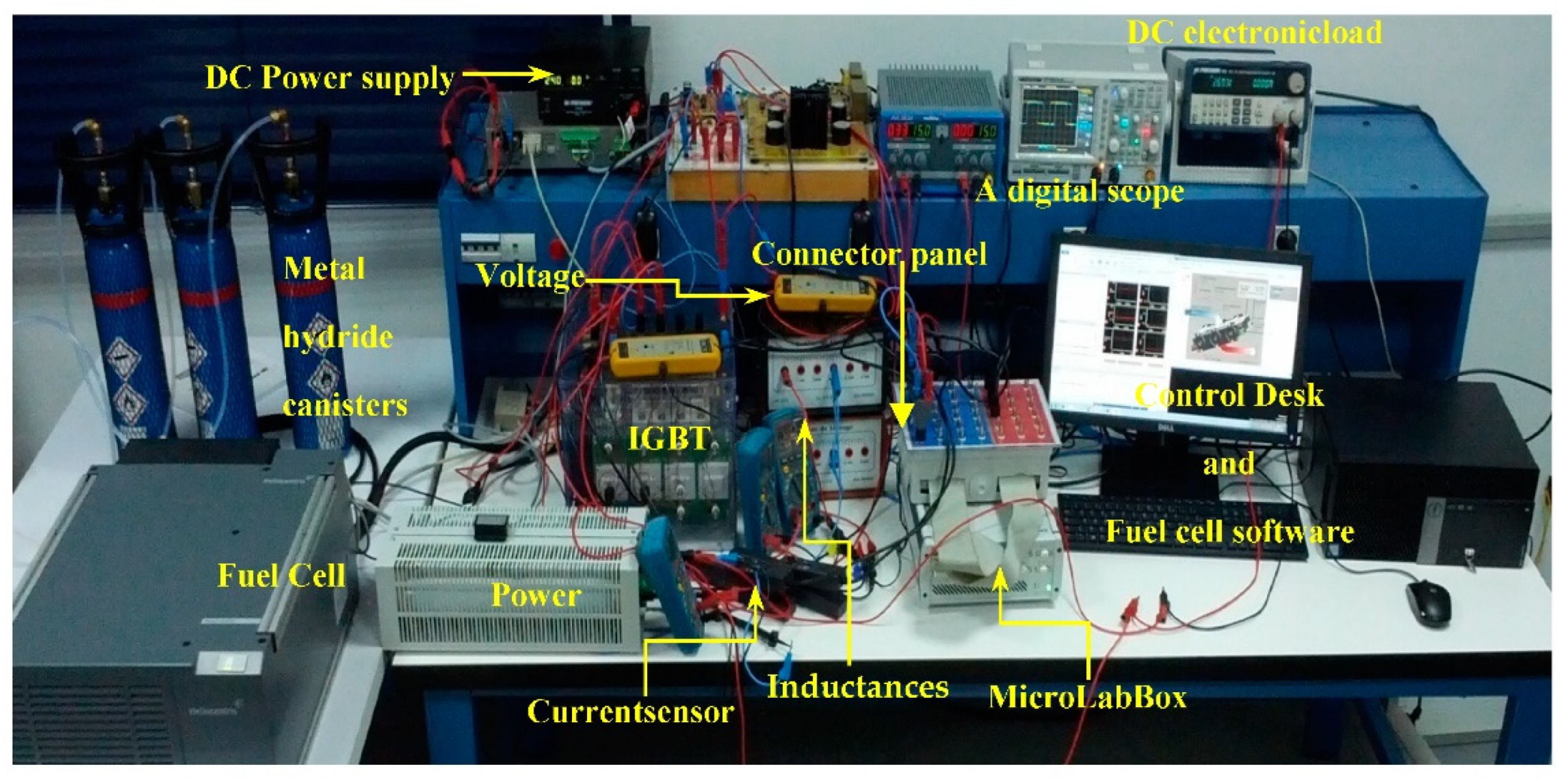
4.2. Experimental Results
- -
- Power supply from BK Precision.
- -
- Power resistors.
- -
- Programmable DC electronic load from BK Precision.
- -
- MicroLabBox-dSPACE DS1202 with Control Desk®/software® plugged in a Pentium 4 personal computer.
- -
- Semikron IGBT module (SEMITEACH).
- -
- Power card together with measurement card.
- -
- Two ferrite inductance.
- -
- Two hall effect current sensors.
- -
- Two voltage sensors.
- -
- A digital scope.
5. Conclusions
Author Contributions
Funding
Institutional Review Board Statement
Informed Consent Statement
Data Availability Statement
Acknowledgments
Conflicts of Interest
References
- Brand, C.; Anable, J.; Ketsopoulou, I.; Watson, J. Road to zero or road to nowhere? Disrupting transport and energy in a zero carbon world. Energy Policy 2020, 139, 111334. [Google Scholar] [CrossRef]
- Chen, H.; Wang, Z.; Xu, S.; Zhao, Y.; Cheng, Q.; Zhang, B. Energy demand, emission reduction and health co-benefits evaluated in transitional China in a 2 °C warming world. J. Clean. Prod. 2020, 264, 121773. [Google Scholar] [CrossRef]
- El Idrissi, Z.; El Fadil, H.; Belhaj, F.Z.; Lassioui, A.; Oulcaid, M.; Gaouzi, K. Theoretical Design and Experimental Validation of a Nonlinear Controller for Energy Storage System Used in HEV. World Electr. Veh. J. 2020, 11, 49. [Google Scholar] [CrossRef]
- Zhang, M.; Fan, X. Review on the State of Charge Estimation Methods for Electric Vehicle Battery. World Electr. Veh. J. 2020, 11, 23. [Google Scholar] [CrossRef]
- Fathabadi, H. Combining a proton exchange membrane fuel cell (PEMFC) stack with a Li-ion battery to supply the power needs of a hybrid electric vehicle. Renew. Energy 2019, 130, 714–724. [Google Scholar] [CrossRef]
- Qi, Z. Proton Exchange Membrane Fuel Cells; CRC Press: Boca Raton, FL, USA, 2013. [Google Scholar]
- James, L. Fuel Cell Systems Explained, 2nd ed.; Wiley: New York, NY, USA, 2003. [Google Scholar]
- Abdelfatah, K.; Gaillard, A.; De Bernardinis, A.; Bethoux, O.; Hissel, D.; Khatir, Z. A review on DC/DC converter architectures for power fuel cell applications. Energy Convers. Manag. 2015, 105, 716–730. [Google Scholar]
- VenkateshNaik, M.; Samuel, P. A Non-Inverting Multi Device Interleaved Buck Boost Converter for Fuel Cell Low Voltage Applications. In Proceedings of the 2019 Global Conference for Advancement in Technology (GCAT), Bangaluru, India, 18–20 October 2019; pp. 1–7. [Google Scholar] [CrossRef]
- Velázquez-Elizondo, P.E.I.; Araujo-Vargas, A.; Villarruel-Parra, F.J.; Gómez-Olguín, K.; Cano, P.; Granados-Luna, T.R. Six-phase dual-interleaved buck-boost converter for high power-density automotive applications. J. Eng. 2019, 17, 3592–3597. [Google Scholar] [CrossRef]
- Izci, D.; Ekinci, S. A novel improved version of hunger games search algorithm for function optimization and efficient controller design of buck converter system. e-Prime—Advances in Electrical Engineering. Electron. Energy 2022, 2, 100039. [Google Scholar] [CrossRef]
- Rahimi, T.; Islam, M.R.; Gholizadeh, H.; Mahdizadeh, S.; Afjei, E. Design and Implementation of a High Step Up DC-DC Converter Based on the Conventional Boost and Buck-Boost Converters with High Value of the Efficiency Suitable for Renewable Application. Sustainability 2021, 13, 10699. [Google Scholar] [CrossRef]
- Thi Kim Nga, T.; Park, S.-M.; Park, Y.-J.; Park, S.-H.; Kim, S.; Van Cong Thuong, T.; Lee, M.; Hwang, K.C.; Yang, Y.; Lee, K.-Y. A Wide Input Range Buck-Boost DC–DC Converter Using Hysteresis Triple-Mode Control Technique with Peak Efficiency of 94.8% for RF Energy Harvesting Applications. Energies 2018, 11, 1618. [Google Scholar] [CrossRef]
- Azer, P.; Emadi, A. Generalized State Space Average Model for Multi-Phase Interleaved Buck, Boost and Buck-Boost DC-DC Converters: Transient, Steady-State and Switching Dynamics. IEEE Access 2020, 8, 77735–77745. [Google Scholar] [CrossRef]
- Rahimi, T.; Ding, L.; Kheshti, M.; Faraji, R. A ZVS Three-Phase Interleaved DC-DC converter with SFM control method for the Microgrid Applications. In Proceedings of the 2020 11th Power Electronics, Drive Systems, and Technologies Conference (PEDSTC), Tehran, Iran, 4–6 February 2020; pp. 1–5. [Google Scholar] [CrossRef]
- Rahimi, T.; Ding, L.; Faraji, R.; Kheshti, M.; Pou, J. Performance Improvement of a Three-Phase Interleaved DC–DC Converter Without Requiring Antisaturation Control for Postfault Conditions. IEEE Trans. Power Electron. 2021, 36, 7378–7383. [Google Scholar] [CrossRef]
- Sampath, S.; Rahiman, Z.; Chenniappan, S.; Sundaram, E.; Subramaniam, U.; Padmanaban, S. Efficient Multi-Phase Converter for E-Mobility. World Electr. Veh. J. 2022, 13, 67. [Google Scholar] [CrossRef]
- Cheddadi, Y.; El Idrissi, Z.; Errahimi, F.; Es-sbai, N. Robust integral sliding mode controller design of a bidirectional DC charger in PV-EV charging station. Int. J. Digit. Signals Smart Syst. 2021, 5, 137–151. [Google Scholar] [CrossRef]
- Elamri, O.; Oukassi, A.; El Bahir, L.; El Idrissi, Z. Combined Vector and Direct Controls Based on Five-Level Inverter for High Performance of IM Drive. World Electr. Veh. J. 2022, 13, 17. [Google Scholar] [CrossRef]
- Gaouzi, K.; El Fadil, H.; Belhaj, F.Z.; El Idrissi, Z. Model predictive control of an inverter for electric vehicles applications. In Proceedings of the 2020 IEEE 2nd International Conference on Electronics, Control, Optimization and Computer Science (ICECOCS), Kenitra, Morocco, 2–3 December 2020. [Google Scholar] [CrossRef]
- Belhaj, F.Z.; El Fadil, H.; Idrissi, Z.E.; Koundi, M.; Gaouzi, K. Modeling, Analysis and Experimental Validation of the Fuel Cell Association with DC-DC Power Converters with Robust and Anti-Windup PID Controller Design. Electronics 2020, 9, 1889. [Google Scholar] [CrossRef]
- Wu, X.; Shi, W.; Du, J. Dual-Switch Boost DC–DC Converter for Use in Fuel-Cell-Powered Vehicles. IEEE Access 2019, 7, 74081–74088. [Google Scholar] [CrossRef]
- El Fadil, H.; Giri, F.; Guerrero, J.M.; Tahri, A. Modeling and Nonlinear Control of a Fuel Cell/Supercapacitor Hybrid Energy Storage System for Electric Vehicles. IEEE Trans. Veh. Technol. 2014, 63, 3011–3018. [Google Scholar] [CrossRef]
- Slah, F.; Mansour, A.; Hajer, M.; Faouzi, B. Analysis, modeling and implementation of an interleaved boost DC-DC converter for fuel cell used in electric. Int. J. Hydrogen Energy 2017, 42, 28852–28864. [Google Scholar] [CrossRef]
- Zhang, Y.; Liu, H.; Li, J.; Sumner, M.; Xia, C. DC–DC Boost Converter With a Wide Input Range and High Voltage Gain for Fuel Cell Vehicles. IEEE Trans. Power Electron. 2019, 34, 4100–4111. [Google Scholar] [CrossRef]
- Gao, D.; Jin, Z.; Liu, J.; Ouyang, M. An interleaved step-up/step-down converter for fuel cell vehicle applications. Int. J. Hydrogen Energy 2016, 41, 22422–22432. [Google Scholar] [CrossRef]
- Intidam, A.; El Fadil, H.; El Idrissi, Z.; Lassioui, A.; Rachid, A.; Jabal Laafou, A. Speed Control of a Brushless DC Motor Powered by a PEM Fuel Cell. In Proceedings of the 2021 9th International Renewable and Sustainable Energy Conference (IRSEC), Morocco, 23–27 November 2021; pp. 1–6. [Google Scholar] [CrossRef]
- Belhaj, F.Z.; El Fadil, H.; El Idrissi, Z.; Intidam, A.; Koundi, M.; Giri, F. New Equivalent Electrical Model of a Fuel Cell and Comparative Study of Several Existing Models with Experimental Data from the PEMFC Nexa 1200 W. Micromachines 2021, 12, 1047. [Google Scholar] [CrossRef] [PubMed]
- Erickson, R.; Maksimovic, D. Power electronics. In Fundamentals of Power Electronics; Springer: New York, NY, USA, 2001. [Google Scholar]
- Yu, X.; Starke, M.R.; Tolbert, L.M.; Ozpineci, B. Fuel cell power conditioning for electric power applications: A summary. IET Electr. Power Appl. 2007, 1, 643–656. [Google Scholar] [CrossRef]
- Fontes, G.; Turpin, C.; Astier, S.; Meynard, T.A. Interactionsbetween fuel cells and power converters: Influence of current harmonics on a fuel cell stack. IEEE Trans Power Electron. 2007, 22, 670e8. [Google Scholar] [CrossRef]
- Rosas-Caro, J.C.; Sanchez, V.M.; Vazquez-Bautista, R.F.; Morales-Mendoza, L.J.; Mayo-Maldonado, J.C.; Garcia-Vite, P.M.; Barbosa, R. A novel DC-DC multilevel SEPIC converter for PEMFC systems. Int. J. Hydrogen Energy 2016, 41, 23401–23408. [Google Scholar] [CrossRef]
- Valdez-Resendiz, J.E.; Sanchez, V.M.; Rosas-Caro, J.C.; Mayo-Maldonado, J.C.; Sierra, J.M.; Barbosa, R. Continuous input-current buck-boost DC-DC converter for PEM fuel cell applications. Int. J. Hydrogen Energy 2017, 42, 30389–30399. [Google Scholar] [CrossRef]
- Gerard, M.; Poirot-Crouvezier, J.-P.; Hissel, D.; Pera, M.-C. Ripple current effects on pemfc aging test by experimental and modeling. ASME J. Fuel Cell Sci. Technol. 2011, 8, 021004. [Google Scholar] [CrossRef]
- Chang, C.; Knights, M.A. Interleaving technique in distributed power conversion systems. IEEE Trans. Circuits Syst. I Fundam. Theory Appl. 1995, 42, 245–251. [Google Scholar] [CrossRef]
- Wang, Y.; Wang, C.-Y. Transient Analysis of Polymer Electrolyte Fuel Cells. Electrochim. Acta 2005, 50, 1307–1315. [Google Scholar] [CrossRef]
- Amrouche, F.; Mahmah, B.; Belhamel, M.; Benmoussa, H. Modélisation d’une Pile à Combustible PEMFC Alimentée Directement en Hydrogène-Oxygène et Validation Expérimentale. Rev. Des Energ. Renouv. 2005, 8, 109–120. [Google Scholar]
- Krein, P.T.; Bentsman, J.; Bass, R.M.; Lesieutre, B.L. On the use of averaging for the analysis of power electronic systems. IEEE Trans. Power Electron. 1990, 5, 182–190. [Google Scholar] [CrossRef]
- Goudarzian, A.; Khosravi, A.; Raeisi, H.A. Optimized sliding mode current controller for power converters with non-minimum phase nature. J. Frankl. Inst. 2019, 356, 8569–8594. [Google Scholar] [CrossRef]
- Khalil, H.K. Nonlinear Systems Analysis; Prentice Hall Inc.: Upper Saddle River, NJ, USA, 2003. [Google Scholar]
- Lee, J.-W. Constructive and discrete versions of the lyapunov’s stability theorem and the lasalle’s invariance theorem. Commun. Korean Math. Soc. 2002, 17, 155–163. [Google Scholar] [CrossRef]


| FC-IBBC system | (7) | |
| (8) | ||
| (9) | ||
| where ; | ||
| Adaptive control laws | (23) | |
| (24) | ||
| (25) | ||
| (28) | ||
| (36) | ||
| (37) | ||
| Adaptive law | (35) | |
| Design parameters | ;; ; ;; | |
| Parameter Designation | Value | |
|---|---|---|
| Fuel Cell | FC open circuit voltage | |
| FC internal capacitor | ||
| Association of the activation and concentration resistances | ||
| Ohmic resistance | ||
| IBBC | Number of IBBC | |
| Filtering inductance | ||
| Filtering capacitor | ||
| ESR of the inductance | ||
| Switching frequency |
| Parameter | Value |
|---|---|
| C11= C12= C13 | 6000 |
| C2 | 10,000 |
| 0.0025 | |
| η0 | 1 |
| Parameter Designation | Value | |
|---|---|---|
| Fuel Cell | Ballard Nexa 1200 fuel cell module the fuel cell has a rated power of 1.2 kW | |
| IBBC | Number of IBBCs | |
| Filtering inductance | ||
| Filtering capacitor | ||
| ESR of the inductance | ||
| Switching frequency | ||
| Parameter | Value |
|---|---|
| C11 = C12 | 2000 |
| C2 | 90,000 |
| 0.002 | |
| η0 | 1.077 |
Publisher’s Note: MDPI stays neutral with regard to jurisdictional claims in published maps and institutional affiliations. |
© 2022 by the authors. Licensee MDPI, Basel, Switzerland. This article is an open access article distributed under the terms and conditions of the Creative Commons Attribution (CC BY) license (https://creativecommons.org/licenses/by/4.0/).
Share and Cite
Koundi, M.; El Idrissi, Z.; El Fadil, H.; Belhaj, F.Z.; Lassioui, A.; Gaouzi, K.; Rachid, A.; Giri, F. State-Feedback Control of Interleaved Buck–Boost DC–DC Power Converter with Continuous Input Current for Fuel Cell Energy Sources: Theoretical Design and Experimental Validation. World Electr. Veh. J. 2022, 13, 124. https://doi.org/10.3390/wevj13070124
Koundi M, El Idrissi Z, El Fadil H, Belhaj FZ, Lassioui A, Gaouzi K, Rachid A, Giri F. State-Feedback Control of Interleaved Buck–Boost DC–DC Power Converter with Continuous Input Current for Fuel Cell Energy Sources: Theoretical Design and Experimental Validation. World Electric Vehicle Journal. 2022; 13(7):124. https://doi.org/10.3390/wevj13070124
Chicago/Turabian StyleKoundi, Mohamed, Zakariae El Idrissi, Hassan El Fadil, Fatima Zahra Belhaj, Abdellah Lassioui, Khawla Gaouzi, Aziz Rachid, and Fouad Giri. 2022. "State-Feedback Control of Interleaved Buck–Boost DC–DC Power Converter with Continuous Input Current for Fuel Cell Energy Sources: Theoretical Design and Experimental Validation" World Electric Vehicle Journal 13, no. 7: 124. https://doi.org/10.3390/wevj13070124
APA StyleKoundi, M., El Idrissi, Z., El Fadil, H., Belhaj, F. Z., Lassioui, A., Gaouzi, K., Rachid, A., & Giri, F. (2022). State-Feedback Control of Interleaved Buck–Boost DC–DC Power Converter with Continuous Input Current for Fuel Cell Energy Sources: Theoretical Design and Experimental Validation. World Electric Vehicle Journal, 13(7), 124. https://doi.org/10.3390/wevj13070124