Article

On Unintentional Demagnetization Effect of Switched Flux Hybrid Magnet Memory Machine

1
Department and Electrical and Electronic Engineering, Suzhou College of Information Technology, Suzhou 215200, China
2
School of Electrical Engineering, Southeast University, Nanjing 210096, China
*
Author to whom correspondence should be addressed.
World Electr. Veh. J. 2022, 13(4), 66; https://doi.org/10.3390/wevj13040066
Submission received: 26 February 2022 / Revised: 28 March 2022 / Accepted: 29 March 2022 / Published: 7 April 2022

Abstract

:
This paper investigates the unintentional demagnetization (UD) characteristics of low-coercive-force (LCF) permanent magnets (PMs), in switched flux hybrid magnet memory machines (SF-HMMMs). Although the LCF PM field is magnetically in parallel to the magnetic fields produced by the NdFeB PM, as well as the armature reaction in the investigated machines, the UD phenomenon of LCF PMs still possibly occurs, particularly, under on-load operation due to the magnetic saturation effect. First, the UD effect is revealed by the frozen permeability method (FPM), and analytically explained via a magnetic circuit model. Various UD types are then identified with the finite-element (FE) method, coupled with a virtual linear hysteresis curve (VLHC) of LCF PM and FPM. In addition, the dimension and grade of the LCF PM are designed with the aid of VLHC, in order to prevent the UD effect. Finally, a fabricated SF-HMMM prototype is tested to verify the theoretical analyses.

1. Introduction

Due to high torque/power density, expedient thermal management and high rotor robustness, switched flux permanent magnet (SFPM) machines are of growing research interest in the last decade [1,2,3,4,5]. Nevertheless, the non-adjustable air-gap flux makes the constant-power speed range of the conventional SFPM machines relatively restricted, which is undesirable for wide-speed-range applications. Therefore, some alternative topologies, equipped with DC field excitations [4], are developed to cope with the limited speed range. However, the continuous excitation copper loss and low efficiency, particularly under high-speed low-load states, are the major issues of those SFPM machines with additional DC field windings.
Very recently, in order to achieve an energy-efficient flux adjustment, the concept of memory machine (MM) [6,7,8,9,10,11,12,13,14,15,16,17,18,19,20,21,22] has been extended to SFPM machines, forming a new type of switched flux hybrid magnet MM (SF-HMMM) [23,24,25]. The auxiliary DC magnetizing coils are employed to generate a current pulse, thereby facilitating the online magnetization, since transient remagnetizing and demagnetizing current pulses are applied to adjust the air-gap flux, which simply requires a short action time with negligible copper losses. In addition, the magnetic saturation will be decreased with the demagnetization of LCF PMs, resulting in a reduction in iron loss. Thus, the efficiency under high-speed operation can be further improved, which will improve the overall driving cycle efficiency desired for EV traction applications. In addition, with a flexible adjustment of the air-gap magnetic field, the CPSR of the machine can be extended to enhance the flux-weakening performance expected for wide-speed-range applications.
Since low-coercive-force (LCF) magnets are utilized in the (SF-HMMM) [24,25,26], the flexible air-gap flux adjustment can be achieved due to the variable magnetization states (MSs) of LCF PMs. It should be noted that MS is characterized by the remanence flux density of the LCF PM under a specific magnetization level, compared to that under full positive magnetization. In this paper, three typical MSs are defined, i.e., flux-enhanced, zero magnetization, as well as flux-weakened, respectively. Meanwhile, the associated excitation copper loss is negligible, resulting in high-efficiency operation, with a wide range of speeds and loads. For the SF-HMMM [24,25,26], two sets of magnets are usually used, in order to improve the torque density, i.e., NdFeB and LCF PMs. In these cases, both excellent low-speed torque-boosting and high-speed flux-weakening capability can be achieved simultaneously. Various new topologies of SF-HMMMs are reported in [27], in terms of either double or single stator structures. The detailed design considerations, including the stator slot/rotor pole combinations, are detailed in [28]. It can be found that the 6-stator slot SF-HMMMs exhibit satisfactory electromagnetic performance, in terms of high torque density, excellent flux adjustability, and high torque to magnet mass ratio. In addition, for the 6-stator slot case, the 13-rotor pole machine has higher torque with low torque ripple, acceptable material cost, and good flux adjustable capability, despite the presence of the unbalanced magnetic pull. However, it is worth noting that though either armature reaction field or NdFeB PM field is theoretically in parallel with LCF PM field in SF-HMMMs, the possibility of the unintentional demagnetization (UD) effect may still exist, especially under on-load operation [27]. This kind of demagnetization refers to the accidental decline in the working points of LCF PM to the unstable nonlinear major line or minor recoil lines of the hysteresis model. Obviously, the UD effect is adverse to the on-load dynamic performance, as well as the accurate online magnetization control. Besides, in the existing literature [23,24,25,26,27,28,29,30,31], an in-depth understanding of the UD mechanism and types, as well as detailed design principle of LCF PM in the DC-magnetized memory machines, is still unreported. Meanwhile, how to reveal the underlying UD mechanism and identify the specific UD type are unexplored. Therefore, this paper has first revealed and investigated why and how the armature reaction and NdFeB PM fields affect the accidental demagnetization, giving the design criterion to avoid the UD, as well as judgement basis for identifying the type of UD, etc. The main advantage over the existing literature refers to the fact this paper utilizes the combined solution of analytical modelling and a numerical hysteresis model, as well as design optimization, considering LCF PM grade to eliminate the UD.
This paper attempts to investigate the UD characteristics of LCF magnets in SF-HMMM comprehensively. The paper is organized as follows: In Section 2, the UD phenomenon and the associated side effects on the electromagnetic performance of the machine are revealed by the frozen permeability method (FPM) [32]. The causes and mechanism of the UD phenomenon is then analytically revealed, with the aid of a simplified magnetic circuit model. In Section 3, different UD types are identified with the FE method, coupled with a virtual linear hysteresis curve (VLHC) of LCF PM and FPM, so as to provide an insightful understanding of the UD phenomenon. In Section 4, the parameters and property of the LCF magnet are optimized with VLHC, in order to establish a general design guideline for eliminating the UD effect. An optimized prototype is manufactured and tested in Section 5, followed by the conclusion in Section 6.

2. Unintentional Demagnetization Effects of SF-HMMM

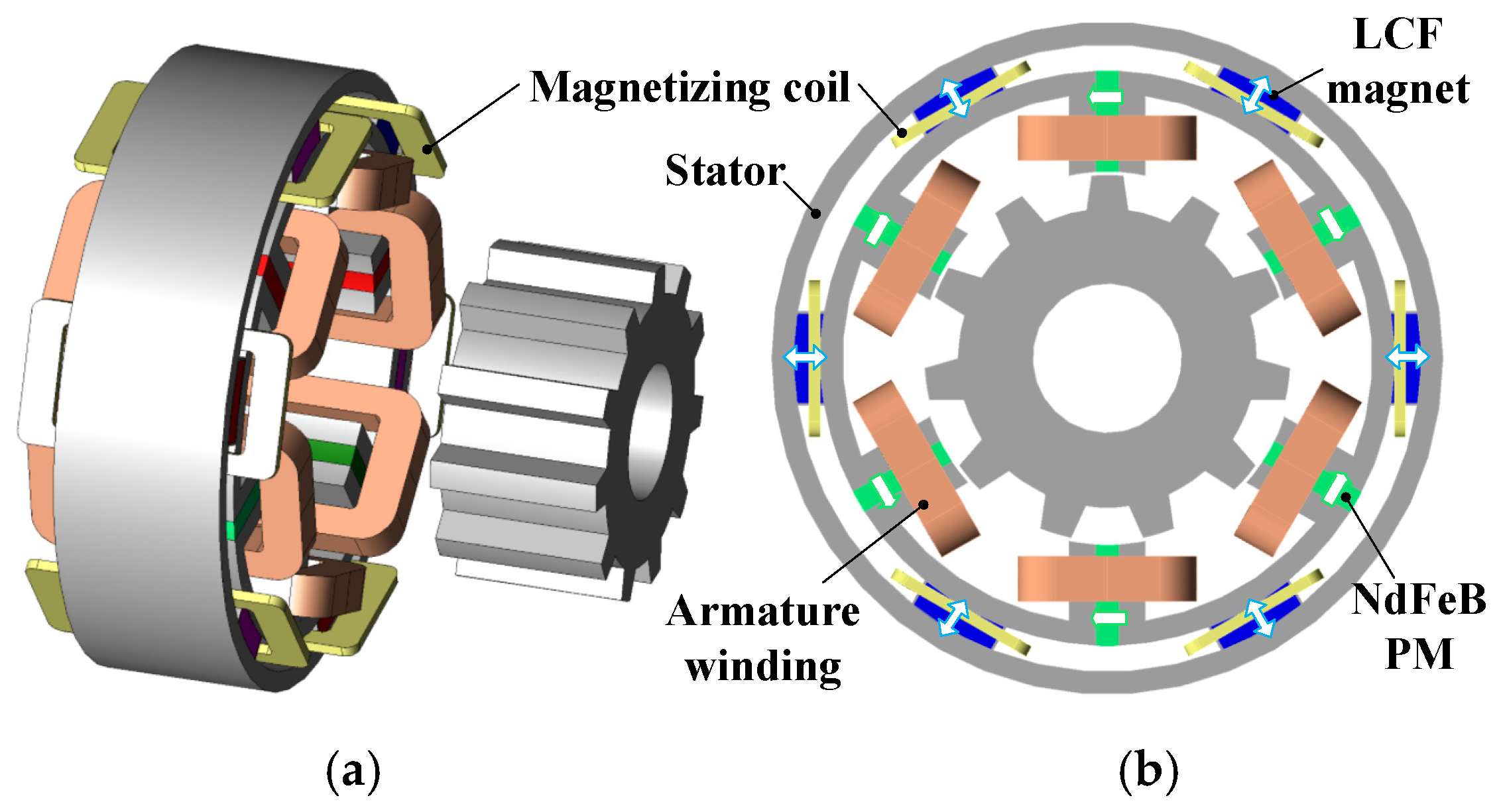
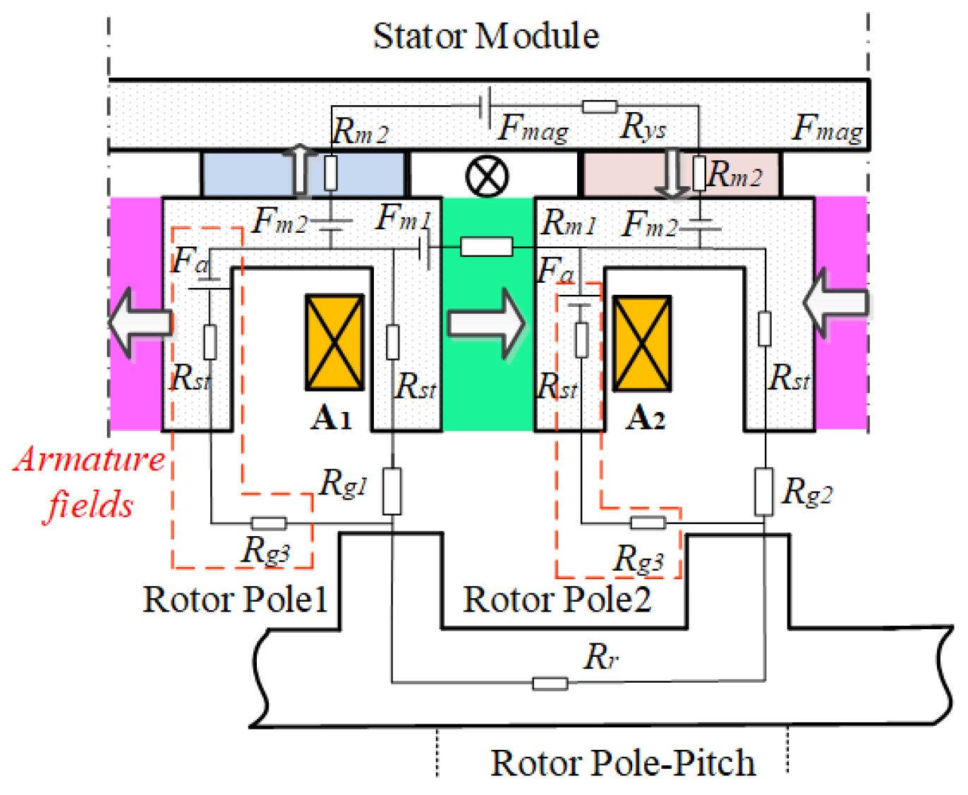
2.1. SF-HMMM Structure

Figure 1 shows the topology of the proposed SF-HMMM, with 6/11 stator-slot/rotor-pole configuration. The tangentially magnetized NdFeB PMs and radially magnetized LCF PMs sandwiched between the outer stator ring and the inner “U” stator segments are located in the stator core. Both hybrid PMs and windings are located on the stator, which permits good armature reaction withstand capability and easy thermal dissipation. It should be noted that in the SF-HMMM design, the magnetizing coil is directly wound on the LCF magnet, in order to facilitate the remagnetization or demagnetization process. The salient rotor with neither magnets nor coils, similar to that of switched reluctance machines, is mechanically robust. The NdFeB PM serves as a dominant contributor for air-gap flux, while the LCF PM acts as a flux adjustor due to its changeable MS.
The investigated SF-HMMM exhibits the advantages of the high torque density of a conventional SFPM flux machine, variable PM flux characteristics, as well as high efficiency maintaining within a duty-cycled operation. It can be seen that the flux leakage exists outside the stator yoke in the SF-HMMM. This phenomenon is resulted by not only the stator/rotor reluctance saliency, but also the nature of the SFPM machine, i.e., the flux modulation machine, which relies on abundant field harmonics for the effective torque production.

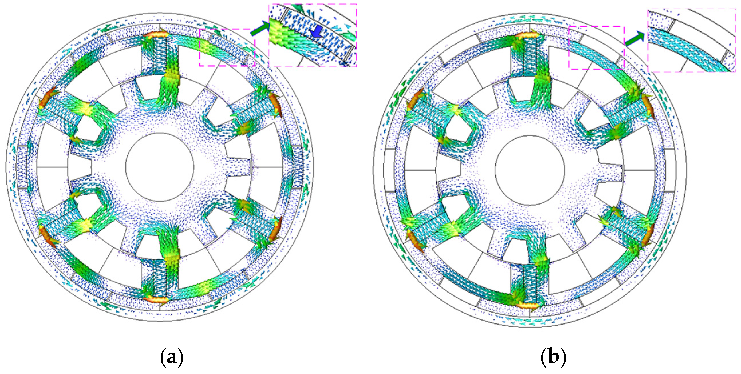
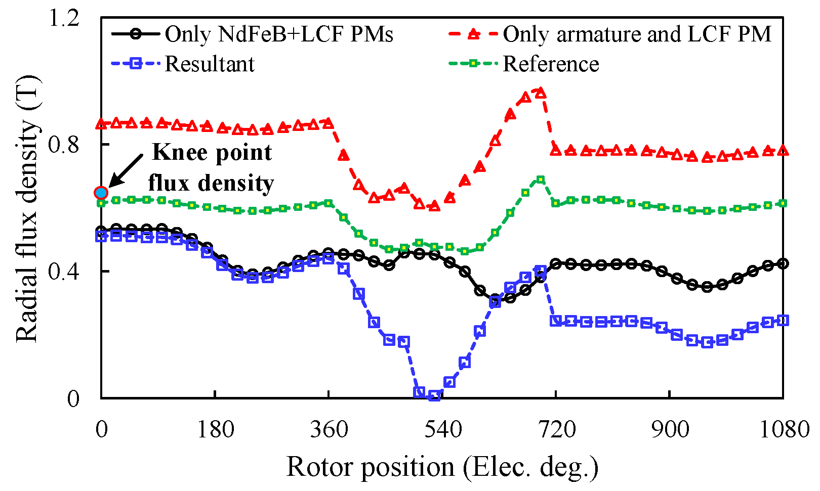
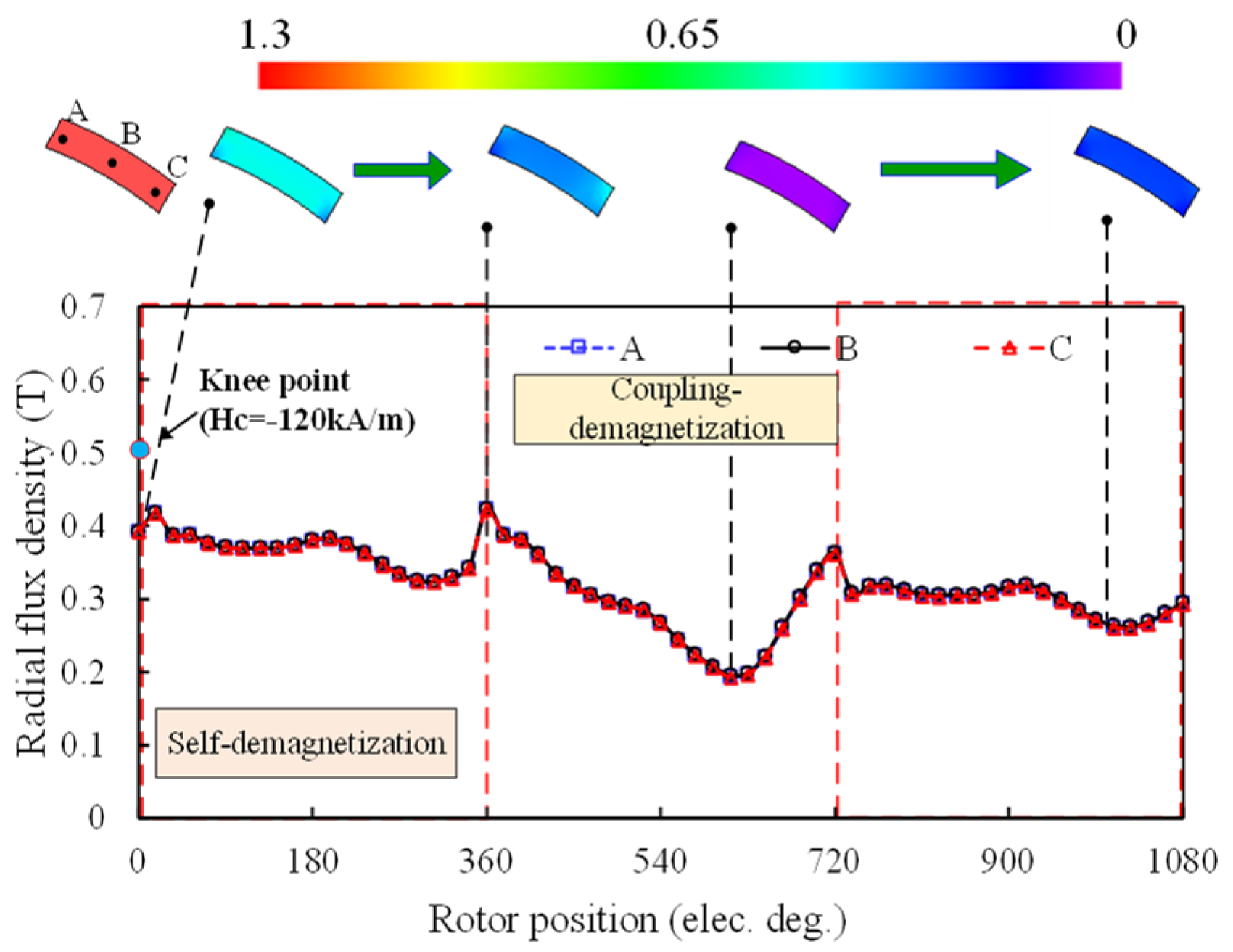
2.2. Description of UD Effect

In order to clearly illustrate the unintentional demagnetization characteristics, a relatively lower coercive force, with “−120 kA/m”, is exemplified in the SF-HMMM first. In fact, the LCF coercive force value will be optimized to avoid the UD effect in Section 4.
The open-circuit field distributions at the flux-enhanced state before or after one electrical cycle of q-axis current excitation (Iq = 14.14 A) are shown in Figure 2. The corresponding variations of radial flux densities of three typical points in the LCF PM are shown in Figure 3. The whole process, reflecting the UD effect, includes three periods. The first and third electrical periods refer to the open-circuit states, while the middle one is the on-load state, which are described as follows.

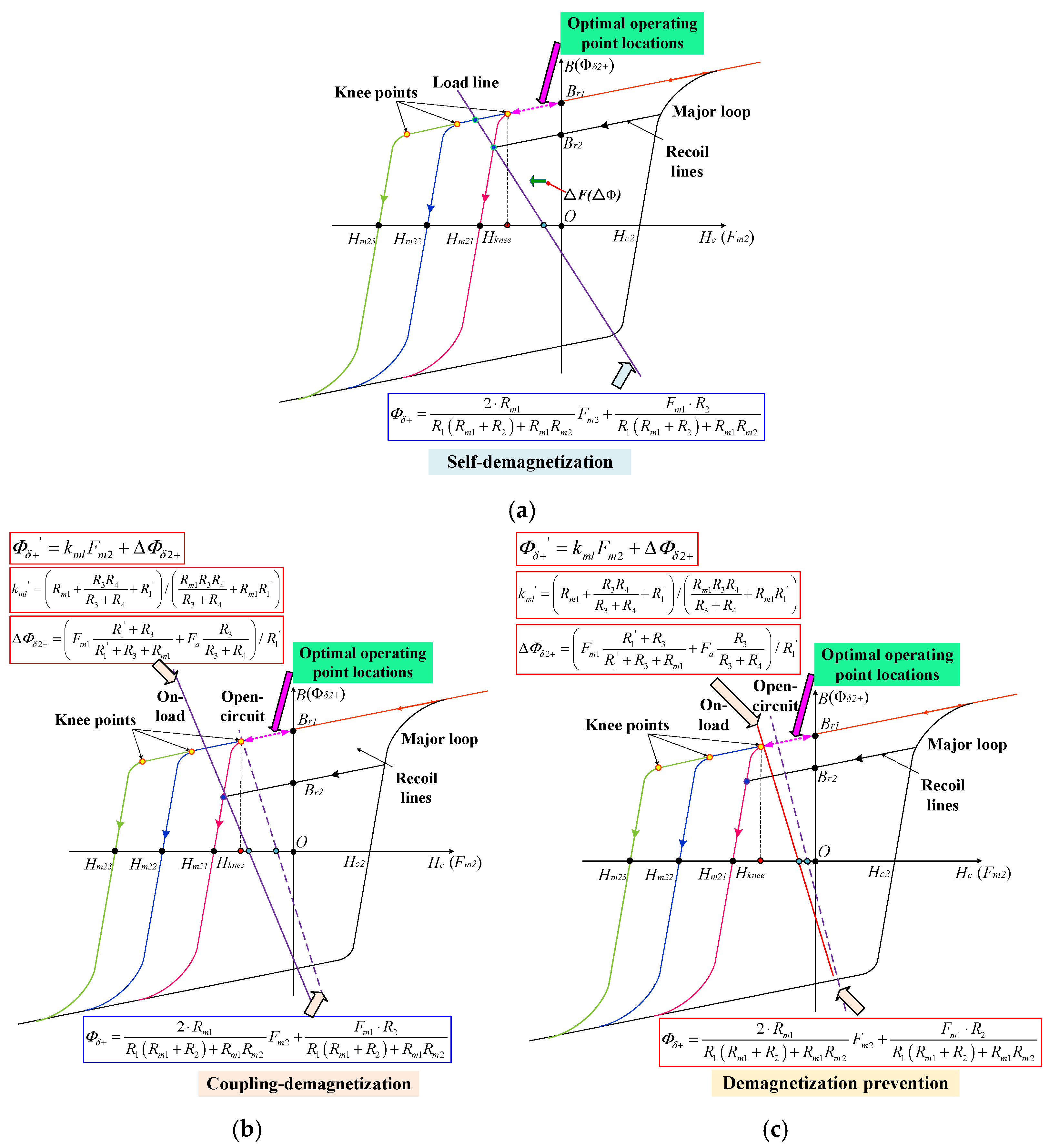
2.2.1. Rotor Position (0°~360°): Self-Demagnetization

During the first electrical period, the operating points of the LCF PM are already below the knee points, i.e., not located in the stable linear region of the hysteresis curve. This means that the magnetic energy of the LCF PM is unable to be effectively utilized. This type of UD can be termed as self-demagnetization of the LCF PM, similar to the effect resulting from a large air-gap.

2.2.2. Rotor Position (360°~720°): Coupling Demagnetization

During the second electrical period, the flux density of the LCF PM drops drastically, followed by the reversion to a higher level after the armature fields are withdrawn. Nevertheless, the operating points of the LCF PM still decline to a lower level compared to the initial state. It implies that the external NdFeB or armature fields have penetrated through the LCF PM during the on-load state, which enforces the operating point to drop down to a lower recoil line. This type of demagnetization can be termed as coupling demagnetization. It should be noted that when the residual flux density and coercivity of LCF PMs are low, the LCF PMs will be reversely magnetized by the NdFeB PMs. This will result in the flux-weakened effect. This phenomenon can also be included in the self-demagnetization category.

2.2.3. Rotor Position (720°~1080°): Post-Demagnetization

When the load current is withdrawn, the LCF PM is demagnetized conspicuously during the on-load operation, though the LCF PM field is magnetically in parallel to the magnetic fields produced by NdFeB PM and the armature reaction. However, it is still unclear whether this UD is caused by the NdFeB PM or armature reaction field during the on-load process. In order to reveal the UD effect, the FPM [32,33] is then employed to extract the actual field distributions of NdFeB PM or armature fields under rated-load operation, which are compared with those without using FPM, as shown in Figure 4. It can be apparently seen that the field distributions, with or without accounting for the on-load magnetic saturation, differ tremendously. This is mainly attributed to the fact that a quantity of NdFeB PM and armature fields circulate through the LCF PMs due to the cross-coupling effect [8], as evidenced in the stator yoke flux density distributions in Figure 4.
The UD effect possibly leads to some adverse effects on the electromagnetic performance, e.g., the reduction of torque capability. Moreover, the demagnetization will make online MS control less predictable.
In order to quantify the UD level and associated performance degradation, an on-load demagnetization ratio kemf, which refers to the reduction ratio of the back-EMF fundamental magnitudes, is defined as [23]
k e m f = E m 1 E m 2 E m 1 × 100 %
where Em1 and Em2 are fundamental back-EMF magnitudes, before and after q-axis current excitation, respectively.
The FE predicted kemf as a function of armature current magnitudes and current angles is shown in Figure 5. It indicates that the LCF magnets are highly sensitive to the armature current magnitude instead of the current angle.
The average electromagnetic torques and kemf resulting from various q-axis current excitations when the LCF PM with coercive force of −120 kA/m is employed are shown in Figure 6. It can be seen that the UD effect is aggravated with the increase in the armature current value, which is mainly attributed to the cross-coupling effect of PM excitation and armature fields. In addition, the flux-linkage and back-EMF diminutions will result in the discrepancy of the reference look-up table of EMF versus magnetizing current at the open-circuit state. Consequently, the precise online MS manipulation control becomes difficult.

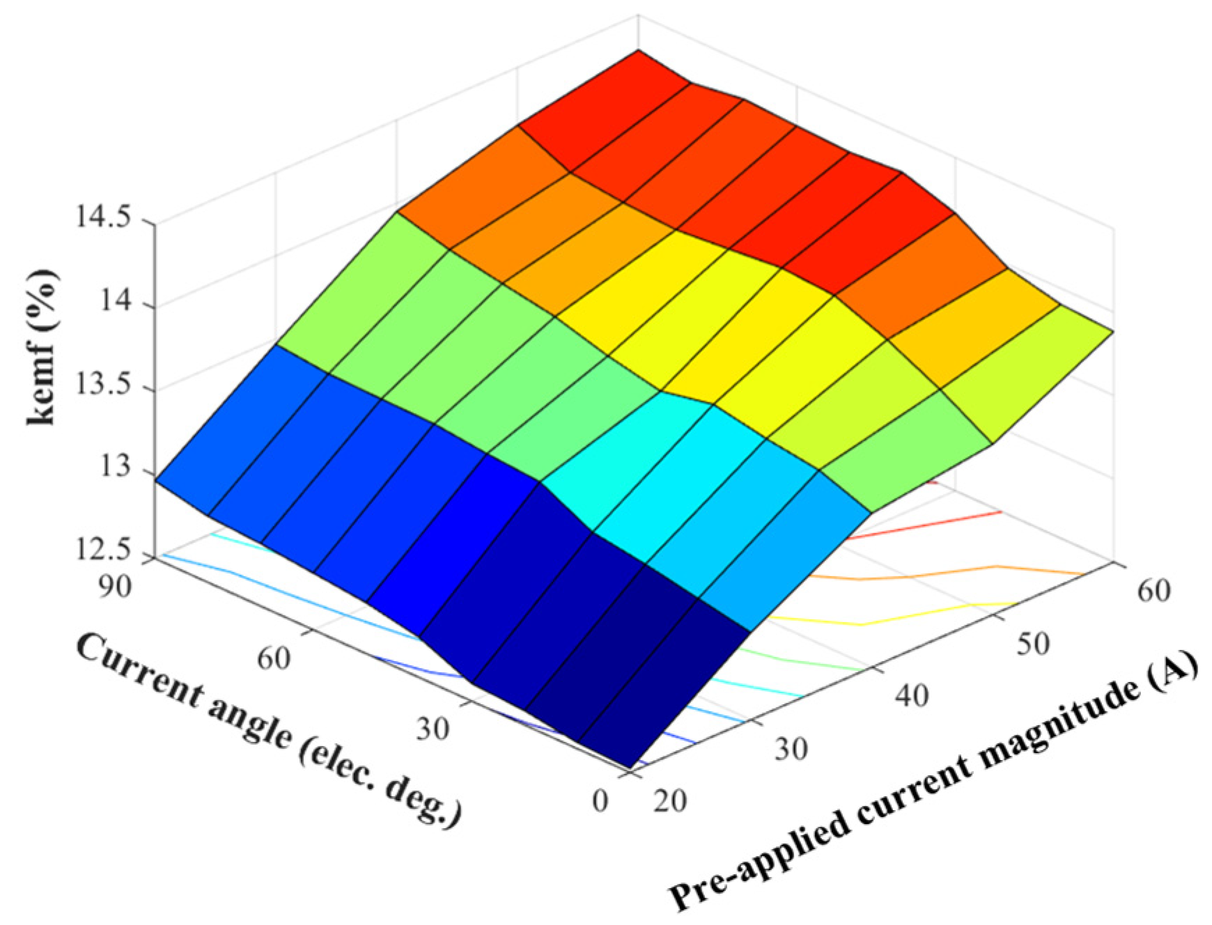
2.3. Analytical Investigation for the UD Phenomenon

In order to clearly illustrate the demagnetization mechanism, the simplified magnetic circuit model, when the rotor aligns with the d-axis, is established as shown in Figure 7. Fmag is the magnetizing MMF.
For the open-circuit condition, the fringing flux leakage is ignored for simplicity, i.e., the bypass air-gap magnetic reluctance Rg3 is assumed to be infinite. Consequently, the maximum open-circuit air-gap flux Φδ+ can be obtained by synthesizing individual magnet excited cases, based on the superimposition method, namely:
Φ δ + = F m 1 ( 2 R m 2 + R y ) + 2 F m 2 R m 1 ( R g 1 + R g 2 + 2 R s t + R r ) ( R m 1 + 2 R m 2 + R r ) + ( 2 R m 2 + R y ) R m 1
where Fm1 and Fm2 are the equivalent magneto-motive force (MMF) of NdFeB PM and LCF PM, respectively; Rm1, and Rm2 are the magnetic reluctances of NdFeB PM and LCF PM, respectively; Ry, Rst, and Rr are the magnetic reluctances of stator yoke, stator tooth and rotor pole, respectively.
The NdFeB and LCF magnets can be modelled as MMF sources, viz.:
F m 1 = H c 1 h m 1
R m 1 = h m 1 μ 0 μ r 1 A m 1
F m 2 = H c 2 h m 2
R m 2 = h m 2 μ 0 μ r 2 A m 2
where hm1 and hm2 are the thicknesses of NdFeB PM and LCF PM, respectively; Hc1 and Hc2 are the coercivities of NdFeB PM and LCF PM, respectively; Am1 and Am2 are the cross-sectional areas of NdFeB PM and LCF PM, respectively; μ0 is the vacuum permeability; Hc1 and Hc2 are the relative permeabilities of NdFeB PM and LCF PM, respectively; and both Rg1 and Rg2 are the air-gap magnetic reluctances.
For the sake of simplification of (2), variables R1 and R2 are defined as follows:
R 1 = 2 R s t + R g 1 + R g 2 + R r
R 2 = 2 R m 2 + R y
By substituting (3)–(8) into (2), the no-load line function for determining the operating point of LCF PMs can be obtained by ignoring the flux leakage, i.e.,:
Φ δ + = 2 × R m 1 R 1 ( R m 1 + R 2 ) + R m 1 R m 2 F m 2 + F m 1 × R 2 R 1 ( R m 1 + R 2 ) + R m 1 R m 2
On the other hand, when the SF-HMMM operates at the on-load operation, the localized magnetic saturation is more likely to occur, particularly in the stator teeth. The equivalent armature reaction MMF Fa should be considered, and consequently, (9) can be rewritten as:
Φ δ + = k m l F m 2 + Δ Φ δ 2 +
where Φδ+’ are the maximum on-load air-gap flux, the slope of the load line, and the horizontal intercept of the load line and:
k m l = ( R m 1 + R 3 R 4 R 3 + R 4 + R 1 ) / ( R m 1 R 3 R 4 R 3 + R 4 + R m 1 R 1 )
Δ Φ δ 2 + = ( F m 1 R 1 + R 3 R 1 + R 3 + R m 1 + F a R 3 R 3 + R 4 ) / R 1
with
R 1 = R s t + R g 2 + R r
R 3 = R g 1 + R s t
R 4 = R g 2 + R s t
It can be found from the above equations that the slope of the load line turns out to be lower than that under no-load operation, as an additional air-gap path with magnetic reluctance R4 is added in the open-circuit case. In addition, the horizontal intercept △Φδ2+ is higher in comparison to the open-circuit one. As a result, it is theoretically identified that the on-load UD tends to be more severe than the open-circuit case.
In order to clearly illustrate the UD phenomenon, a set of LCF hysteresis curves, having various coercive force values, are shown in Figure 8 Obviously, the hysteresis nonlinearity and the coercive force values significantly affect the location of the operating points.

2.3.1. Self-Demagnetization

For the self-demagnetization, it can be inferred from (9) that if the NdFeB magnet usage increases, it results in magnetic saturation. Thus, the slope of the load line decreases with the increase in R1. In this case, the self-demagnetization will occur, as shown in Figure 8a.

2.3.2. Coupling Demagnetization

For the coupling demagnetization case, when the load current rises under on-load operation, Fa will increase, resulting in the increment of ΔΦδ2+. Consequently, the load line will shift along the negative horizontal axis, and the working points drop to a lower recoil line. This means that the coupling demagnetization will happen, as illustrated in Figure 8b.
Based on (9)~(15), in order to prevent the UD effect, the value of Rm1 can be designed lower, and the magnetic saturation of the stator core should be reduced, with decreasing R1 to R4. Alternatively, when the coercive force of the LCF PM increases, the load line is located on the linear region, as illustrated in Figure 8c. As a whole, the underlying causes for the UD effect have been analytically identified and explained.

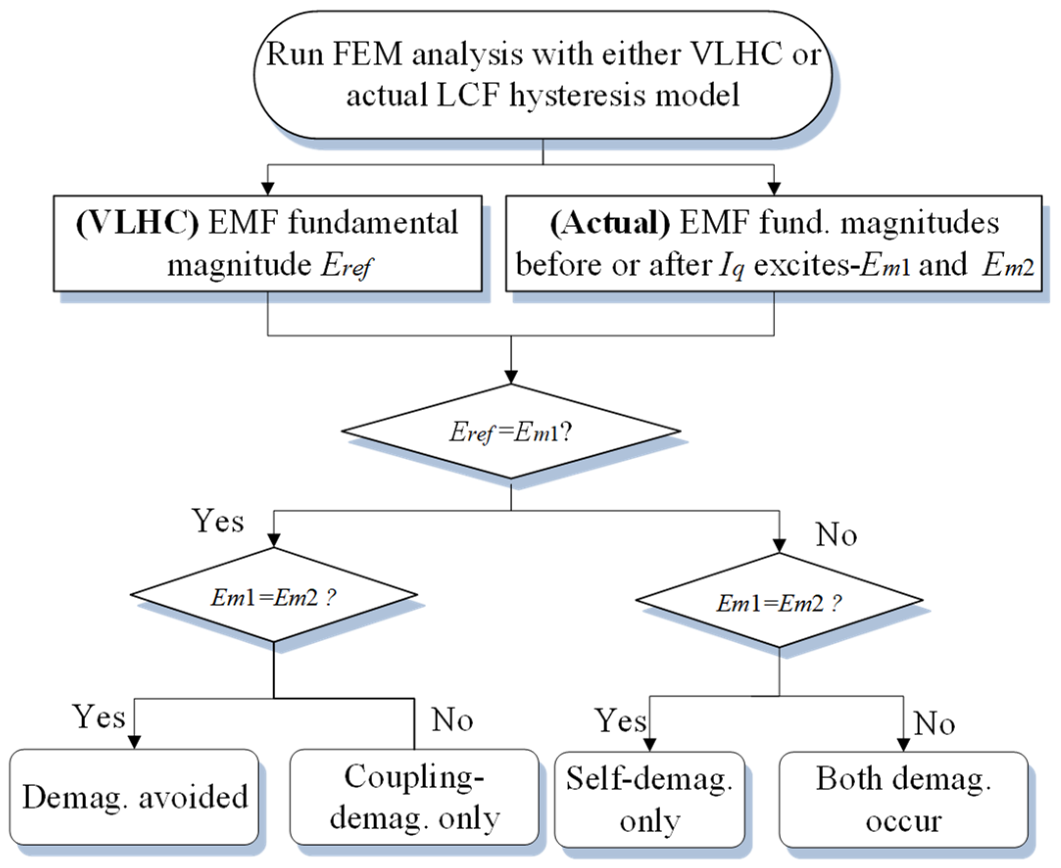
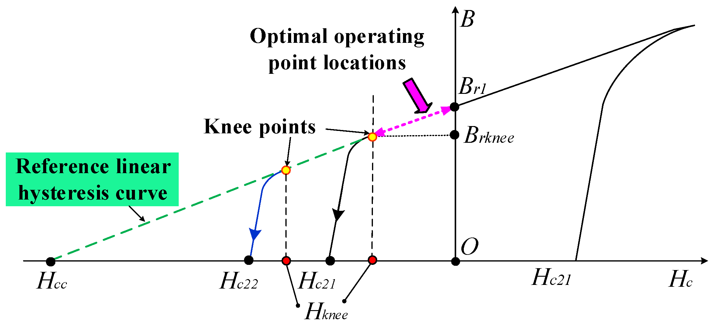
3. Demagnetization Type Identification

The identification of the UD type is crucial for understanding the demagnetization mechanism and establishing the design approach to eliminating the UD effect. Nonetheless, in practice, although the demagnetization of the LCF PM can be detected by observing the magnetic fields inside, it is still a bit troublesome to distinguish the demagnetization type using direct FE simulation [8], particularly in the case of a small part of the PM demagnetized region. In the direct FE, the flux density of each PM element is required to compare with the threshold values of the knee points. Therefore, it is necessary to develop a new method, so as to identify the demagnetization type in a computationally efficient manner.
First, we propose a VLHC [27], as illustrated in Figure 9, which is able to identify what kinds of UD effects occur. The performance degradation level caused by this undesired demagnetization behavior is also estimated. Obviously, the VLHC can be treated as an extended line of the upper recoil line of the LCF magnet. The function of the VLHC in the second quadrant can be given by:
B = B r k n e e + μ 0 μ r 2 ( H H k n e e )
where Brknee, and Hknee are the knee point of the hysteresis model of the LCF PM and the knee point coercivity of LCF PM, namely.
Then, the VLHC is assigned to a new PM material to replace the original nonlinear one, and an alternate FE analysis, similar to the process described in Figure 3, is carried out with FPM [33]. The resultant fundamental magnitudes of back-EMFs are then compared with those results obtained from the FE analyses, with actual LCF PM subject to q-axis current excitations. Here, Eref is defined as the fundamental back-EMF obtained by the VLHC model.
The VLHC model is able to provide a quick solution to identify and quantify different demagnetization types, as well as levels, which is quite different from the case of the NdFeB PM. This is also helpful to understand the UD mechanism in a quantitative way. In addition, the VLHC can facilitate the design optimization and analysis process, since it provides a direct index to confirm whether the UD occurs.
The overall identification flowchart is shown in Figure 10, which can be described as follows: initially, if Eref and Em1 are equal, the initial working points are located on the upper limit recoil line. In other words, the self-demagnetization can be prevented. Furthermore, by comparing Em1 and Em2, if they are equal, the UD effect can be avoided. Otherwise (Em1 > Em2), only the coupling UD effect occurs, and the working points of the LCF PMs will shift to the lower recoil lines during the on-load operation.
On the other hand, if Eref > Em1, both UD types possibly occur, and the situations can be analogously subdivided into two cases, according to the relation between Em1 and Em2. First, if Em1 and Em2 are equal, only the self-demagnetization occurs. Otherwise, both kinds of UDs simultaneously exist.
The FPM is utilized to extract the individual contribution of either NdFeB PM or armature fields to the demagnetization of the LCF magnets. First, when the armature current excitation is removed, the variation of flux density in the PM point A (see Figure 3) is shown in Figure 11. When the LCF PM and armature excitations are simultaneously considered, the variation results are analogously obtained as well. It can be observed that both NdFeB and armature fields cause the on-load UD of the LCF PMs. In addition, as illustrated in Table 1, the satisfactory agreement of the summation of the individual cases and the resultant case has validated the effectiveness of this analysis method. These analysis results are employed to identify which excitation source is responsible for the UD effect of the LCF PMs. This can help a machine designer to understand the underlying UD mechanism better, and design the magnetic circuit of the SF-HMMM in a reasonable way.

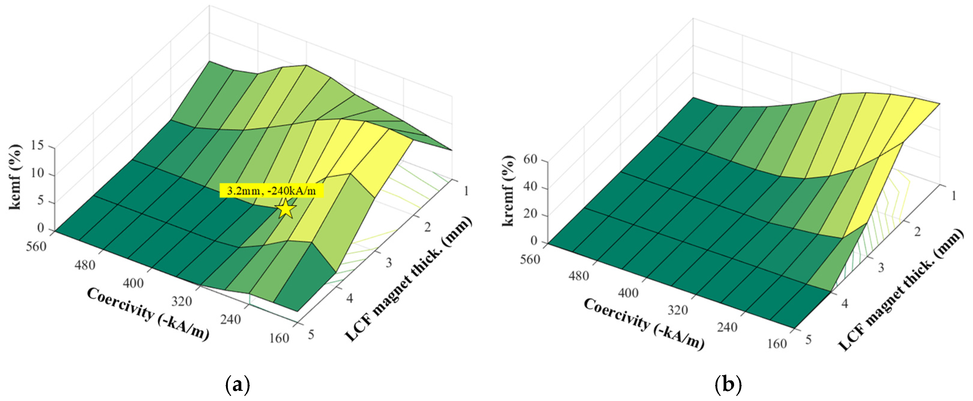
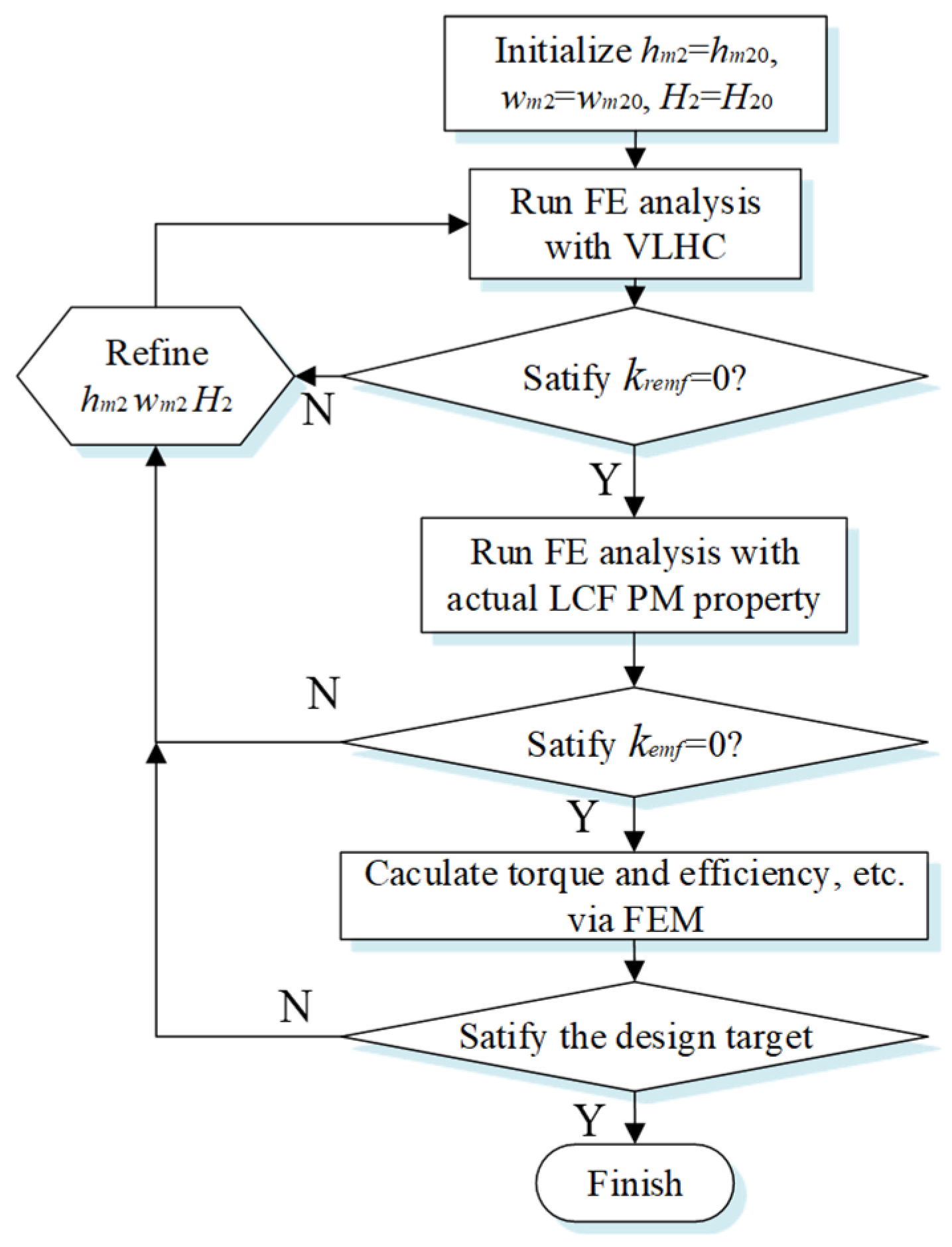
4. LCF PM Design Guidelines for Elimination of UD Effect

This section focuses on the optimization of sizing and grade of the LCF magnets, which is of great significance for the prevention of the UD effect. Initially, a reference demagnetization ratio kremf is utilized to indicate whether the self-demagnetization occurs prior to the load current excitation, which is defined as:
k r e m f = E r e f E m 1 E r e f × 100 %
It should be noted that the FPM is used to freeze the iron permeability, in each case, so as to conduct a fair comparison with the actual cases. As a result, the variations in kremf and kemf with Hc2 and hm2 are shown in Figure 12.
It can be observed that both demagnetization ratios experience a fluctuation with the increase in the PM thickness, since the reversed remagnetization of the LCF PM with lowwer coercivity and thickness is caused by the NdFeB magnetic field. It shows that the parameters of “hm2 = 3.2 mm and coercivity Hc2 = −240 kA/m” are selected for the final design, which can well prevent both the coupling and self-demagnetizations. The overall design process of the sizing and grade of the LCF PM is illustrated in Figure 13.

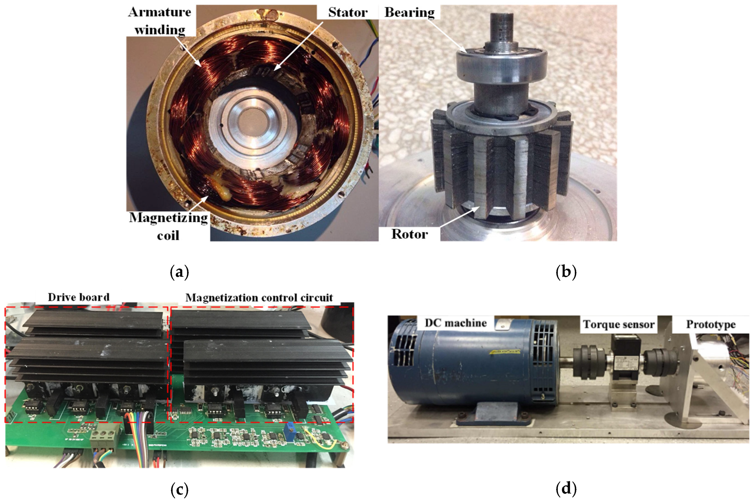
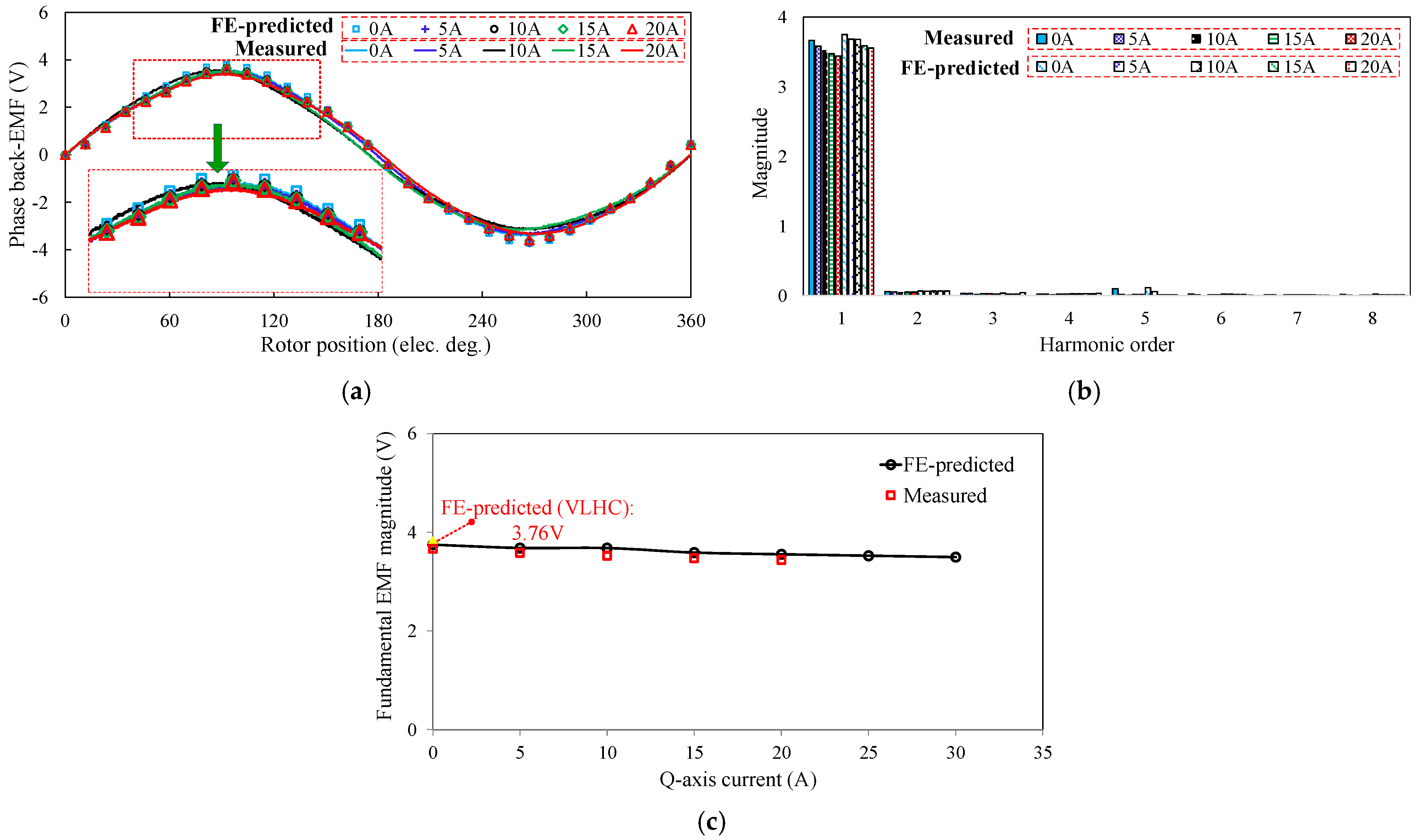
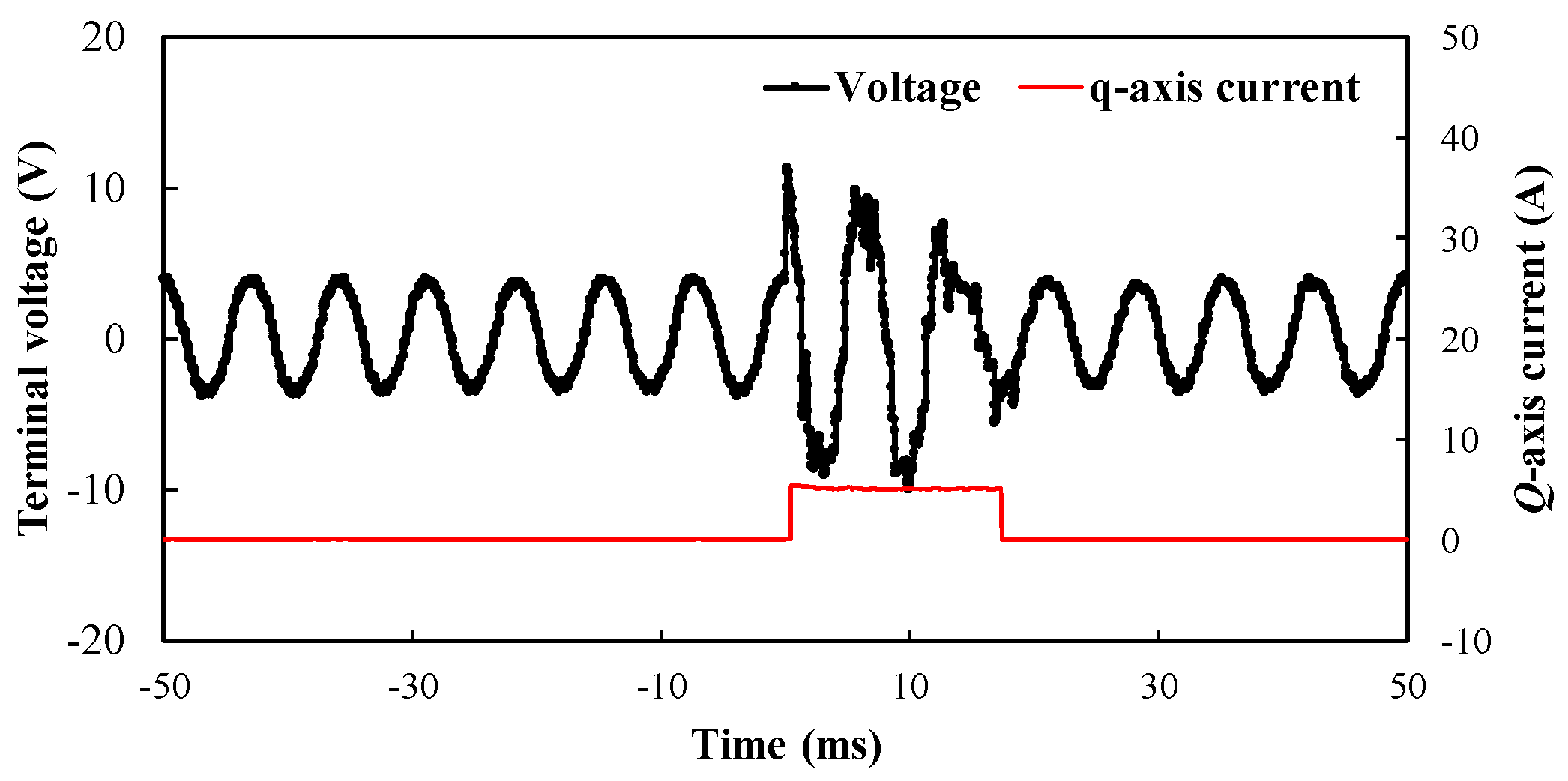
5. Experimental Validation

A 6/11-pole SF-HMMM prototype is manufactured and tested, in order to verify the foregoing theoretical analyses. The stator/rotor assemblies, control board and test platform are shown in Figure 14. The design specifications of the prototype are listed in Table 2. The circuit board, including the drive and magnetization control modules, is shown in Figure 14c. The test setup is shown in Figure 14c, which is employed to measure the machine dynamic performance and torque speed curve. The prototype is coupled to a brushed DC machine as the load generator. Meanwhile, an encoder is utilized for rotor position detection and a torque transducer is for torque measurement.
When LCF PMs of the prototype are initialized as full MSs, the open-circuit phase back-EMF is initially pre-measured as a reference benchmark. Afterwards, the prototype machine is initially fed by various magnitudes of q-currents, and then the loaded currents are subsequently withdrawn. As a consequence, the resultant open-circuit back-EMFs are tested after withdrawing. In fact, the measurements refer to the open-circuit back-EMFs before or after applying q-axis current excitation. The main purpose is to reflect the unintentional demagnetization effect caused by the q-axis current. The FE-predicted and measured open-circuit back-EMF waveforms are shown in Figure 15. In order to reflect this process, the open-circuit voltage response to a temporary q-axis current of 5A is illustrated in Figure 16. Meanwhile, the torque against current characteristics, with or without VLHC, are plotted in Figure 17. Overall, satisfactory agreement between the FE predictions and measurements is achieved. It demonstrates that the back-EMF rarely varies with the increase in loaded currents. Furthermore, the fundamental back-EMFs and torques are basically equal to the FE-predicted ones, running with VLHC. It implies that the MSs of LCF magnets are well maintained under the on-load condition. As a result, the UD effect can be effectively prevented as can be evidenced in Figure 15c that shows the variations of fundamental EMF with the q-axis currents. The above experiment results confirm the foregoing theoretical analyses and design approach.

6. Conclusions

In this paper, the UD effects of LCF PMs in SF-HMMMs were comprehensively investigated. It can be found that though the fields excited by PMs and armature reaction are in parallel, the UD of LCF PMs still occurs, particularly under heavy on-load operations. The FPM is employed to reveal the UD effect, and it shows that the LCF magnets are highly sensitive to the load current magnitude, rather than the current angle. Meanwhile, the UD effect is aggravated with the increase in the load current value. A simplified magnetic circuit model is utilized to analytically reveal the UD mechanism, which indicates that the cross-coupling magnetic saturation is mainly responsible for the UD effect. A VLHC of LCF PM is then developed to identify various UD types. It demonstrates that there are mainly two kinds of UD types, i.e., self- and coupling UDs, which are caused by the undesired deviations in the load line, under open-circuit and on-load states, respectively. The design guidelines for the PM sizing and grade are established, which can well prevent the UD effect. The theoretical analyses are validated by the experiments on an SF-HMMM prototype. Overall, it should be further emphasized that more specific and special LCF magnets with higher electromagnetic performance, as well as a simpler mechanical structure, should be developed in the future, in order to extend the serving life cycle of the proposed SF-HMMM.

Author Contributions

Conceptualization, J.F. and H.Y.; methodology, H.Y.; software, Y.G.; validation, J.F. writing—original draft preparation, J.F. and H.Y.; writing—review and editing, validation H.Y. and W.Z.; visualization, Y.G.; supervision, H.Y.; project administration, H.Y.; funding acquisition, H.Y. All authors have read and agreed to the published version of the manuscript.

Funding

This work was supported, in part, by the National Natural Science Foundations of China (52037002 and 52077033), in part by the Fundamental Research Funds for the Central Universities (2242017K41003), in part by the “SEU Zhishan scholars” Program of Southeast University (2242019R40042), in part by the Key R&D Program of Jiangsu Province (BE2021052) and “Thousand Talents Plan” Project of Jiangxi Province (jxsq2020102088), and in part by “the Excellence Project Funds of Southeast University”.

Institutional Review Board Statement

Not applicable.

Informed Consent Statement

Not applicable.

Data Availability Statement

Not applicable.

Conflicts of Interest

The authors declare no conflict of interest.

References

  1. Ullah, W.; Khan, F.; Sulaiman, E.; Umair, M. Torque characteristics of high torque density partitioned PM consequent pole flux switching machines with flux barriers. CES Trans. Electr. Mach. Syst. 2020, 4, 130–141. [Google Scholar] [CrossRef]
  2. Li, S.; Li, Y.; Sarlioglu, B. Partial Irreversible Demagnetization Assessment of Flux-Switching Permanent Magnet Machine Using Ferrite Permanent Magnet Material. IEEE Trans Magn. 2015, 51, 1–9. [Google Scholar]
  3. Zhu, Z.Q.; Chen, J.T. Advanced flux-switching permanent magnet brushless machines. IEEE Trans. Magn. 2010, 46, 1447–1453. [Google Scholar] [CrossRef]
  4. Fasolo, A.; Alberti, L.; Bianchi, N. Performance comparison between switching-flux and IPM machine with rare earth and ferrite PMs. IEEE Trans. Ind. Appl. 2014, 50, 3708–3716. [Google Scholar] [CrossRef]
  5. Zhang, H.; Hua, W.; Zhang, G. Analysis of Back-EMF Waveform of a Novel Outer-Rotor-Permanent-Magnet Flux-Switching Machine. IEEE Trans. Magn. 2017, 53, 1–4. [Google Scholar] [CrossRef]
  6. Ostovic, V. Memory motors. IEEE Ind. Appl. Mag. 2003, 9, 52–61. [Google Scholar] [CrossRef]
  7. Yang, H.; Lin, H.; Zhu, Z.Q. Recent advances in variable flux memory machines for traction applications: A review. CES Trans. Electr. Mach. Syst. 2018, 2, 34–50. [Google Scholar] [CrossRef]
  8. Wu, D.; Zhu, Z.Q.; Pride, A.; Deodhar, R.; Sasaki, T. Cross coupling effect in hybrid magnet memory machine. In Proceedings of the 7th IET International Conference on Power Electronics, Machines and Drives (PEMD 2014), Manchester, UK, 8–10 April 2014; pp. 1–6. [Google Scholar]
  9. Athavale, A.; Sasaki, K.; Kato, T.; Lorenz, R. Magnetization state estimation in variable-flux PMSMs. In Proceedings of the 2017 IEEE International Electric Machines and Drives Conference (IEMDC), Miami, FL, USA, 21–24 May 2017; pp. 1–8. [Google Scholar]
  10. Song, J.Y.; Lee, J.H.; Kim, D.W.; Kim, Y.J.; Jung, S.Y. Analysis and modeling of permanent magnet variable flux memory motors using magnetic equivalent circuit method. IEEE Trans. Magn. 2017, 53, 1–5. [Google Scholar] [CrossRef]
  11. Maekawa, S.; Yuki, K.; Matsushita, M.; Nitta, I.; Hasegawa, Y.; Shiga, T.; Hosoito, T.; Nagai, K.; Kubota, H. Study of the magnetization method suitable for fractional-slot concentrated-winding variable magnetomotive-force memory motor. IEEE Trans. Power Electron. 2014, 29, 4877–4887. [Google Scholar] [CrossRef]
  12. AI, Q.; Wei, H.; Zhang, Y. Optimal design for Flux-intensifying Permanent Magnet Machine Based on Neural Network and Multi-objective optimization. In Proceedings of the 2020 4th CAA International Conference on Vehicular Control and Intelligence (CVCI), Hangzhou, China, 18–20 December 2020; pp. 596–601. [Google Scholar]
  13. Chen, J.; Li, J.; Qu, R. Maximum-torque-per-ampere and magnetization-state control of a variable-flux permanent magnet machine. IEEE Trans. Ind. Electron. 2018, 65, 1158–1169. [Google Scholar] [CrossRef]
  14. Ibrahim, M.; Masisi, L.; Pillay, P. Design of variable flux permanent magnet machine for reduced inverter rating. IEEE Trans. Ind. Appl. 2015, 51, 3666–3674. [Google Scholar] [CrossRef]
  15. Tsunata, R.; Takemoto, M.; Ogasawara, S.; Orikawa, K. Variable Flux Memory Motor Employing Double-Layer Delta-Type PM Arrangement and Large Flux Barrier for Traction Applications. IEEE Trans. Ind. Appl. 2021, 57, 3545–3561. [Google Scholar] [CrossRef]
  16. Hu, Y.; Chen, B.; Xiao, Y.; Li, X.; Chen, J.; Fang, H. Comprehensive control of a hybrid-magnet variable-flux memory machine for washing machine applications. In Proceedings of the 2021 IEEE 4th International Electrical and Energy Conference (CIEEC), Wuhan, China, 28–30 May 2021; pp. 1–6. [Google Scholar]
  17. de Sousa, F.D.; Battiston, A.; Pierfederici, S.; Meibody-Tabar, F. Validation of the standstill magnetization strategy of a FeCrCo-based variable flux memory machine. In Proceedings of the 2021 24th International Conference on Electrical Machines and Systems (ICEMS), Gyeongju, Korea, 31 October–3 November 2021; pp. 536–541. [Google Scholar]
  18. Sakai, K.; Yoneda, K.; Suzuki, W. Variable-magnetization interior permanent magnet motor yield widely variable flux due to small magnetizing current and operating at high power over a wide speed range. In Proceedings of the 2021 IEEE Energy Conversion Congress and Exposition (ECCE), Vancouver, BC, Canada, 10–14 October 2021; pp. 4205–4212. [Google Scholar]
  19. Xu, H.; Li, J.; Chen, J.; Lu, Y.; Ge, M. Analysis of a hybrid permanent magnet variable-flux machine for electric vehicle tractions considering magnetizing and demagnetizing current. IEEE Trans. Ind. Appl. 2021, 57, 5983–5992. [Google Scholar] [CrossRef]
  20. Zhu, X.; Xiang, Z.; Quan, L.; Wu, W.; Du, Y. Multimode optimization design methodology for a flux-controllable stator permanent magnet memory motor considering driving cycles. IEEE Trans. Ind. Electron. 2018, 65, 5353–5366. [Google Scholar] [CrossRef]
  21. Yang, H.; Lyu, S.; Lin, H.; Zhu, Z.; Zheng, H.; Wang, T. A Novel Hybrid-Magnetic-Circuit Variable Flux Memory Machine. IEEE Trans. Ind. Electron. 2020, 67, 5258–5268. [Google Scholar] [CrossRef]
  22. Chen, Z.; Lin, H.; Zhong, Y.; Lyu, S.; Yang, H. A Novel Current Control Strategy for Magnetization State Manipulation of Variable Flux Memory Machine Based on Linear Active Disturbance Rejection. IEEE Trans. Power Electron. 2022, 37, 1962–1971. [Google Scholar] [CrossRef]
  23. Yang, H.; Zhu, Z.Q.; Lin, H.; Lyu, S. Comparative study of hybrid PM memory machines having single- and dual-stator configurations. IEEE Trans. Ind. Electron. 2018, 65, 9168–9178. [Google Scholar] [CrossRef]
  24. Yang, H.; Lyu, S.; Lin, H.; Zhu, Z. Stepwise Magnetization Control Strategy for DC-Magnetized Memory Machine. IEEE Trans. Ind. Electron. 2019, 66, 4273–4285. [Google Scholar] [CrossRef] [Green Version]
  25. Yang, H.; Lin, H.; Zhu, Z.Q.; Wang, D.; Fang, S.; Huang, Y. A variable-flux hybrid-PM switched-flux memory machine for EV/HEV applications. IEEE Trans. Ind. Appl. 2016, 52, 2203–2214. [Google Scholar] [CrossRef]
  26. Yang, H.; Zhu, Z.Q.; Lin, H.; Wu, D.; Hua, H.; Fang, S.; Huang, Y. Novel high-performance switched flux hybrid magnet memory machines with reduced rare-earth magnets. IEEE Trans. Ind. Appl. 2016, 52, 3901–3915. [Google Scholar] [CrossRef]
  27. Yang, H.; Zhu, Z.Q.; Lin, H.; Guo, K.; Guo, Y.; Fang, S.; Huang, Y. Analysis of on-load magnetization characteristics in a novel partitioned stator hybrid magnet memory machine. IEEE Trans. Magn. 2017, 53, 1–4. [Google Scholar] [CrossRef]
  28. Yang, H.; Zhu, Z.Q.; Lin, H.; Xu, P.L.; Zhan, H.L.; Fang, S.; Huang, Y. Design synthesis of switched flux hybrid-permanent magnet memory machines. IEEE Trans. Energy Convers. 2017, 32, 65–79. [Google Scholar] [CrossRef]
  29. Yang, H.; Lin, H.; Zhu, Z.Q.; Niu, S.; Lyu, S.; Zheng, H. A Novel Stator Spoke-Type Hybrid Magnet Memory Machine. In Proceedings of the 2019 IEEE International Electric Machines & Drives Conference (IEMDC), San Deigo, CA, USA, 12–15 May 2019; pp. 1576–1580. [Google Scholar]
  30. Wu, D.; Liu, X.; Zhu, Z.Q.; Pride, A.; Deodhar, R.; Sasaki, T. Switched flux hybrid magnet memory machine. IET Electron. Power Appl. 2015, 9, 160–170. [Google Scholar] [CrossRef]
  31. Yang, G.; Lin, M.; Li, N.; Fu, X.; Liu, K. Maximum torque output control of hybrid permanent magnet axial field flux-switching memory machine. In Proceedings of the 2017 IEEE Energy Conversion Congress and Exposition (ECCE), Cincinnati, OH, USA, 1–5 October 2017; pp. 1212–1219. [Google Scholar]
  32. Jiang, J.; Niu, S. A novel slot-PM-assisted hybrid magnet memory machine. IEEE Trans. Magn. 2022; in press. [Google Scholar]
  33. Shuto, D.; Takahashi, Y.; Fujiwara, K. Frozen Permeability Method for Magnetic Field Analysis of Permanent Magnet Motors Considering Hysteretic Property. IEEE Trans. Magn. 2019, 55, 1–4. [Google Scholar] [CrossRef]
Figure 1. Topology of the investigated SF-HMMM. (a) 3D exploded view. (b) Cross-sectional view.
Wevj 13 00066 g001
Figure 2. Illustration of on-load UD effect: open-circuit field distributions (a) before or (b) after the q-axis current excitation (Iq = 14.14 A).
Wevj 13 00066 g002
Figure 3. Variation of the working point of PM elements subject to one electrical period of q-axis current excitation (Iq = 14.14A).
Wevj 13 00066 g003
Figure 4. On-load demagnetization effect: field distributions excited by (a) NdFeB only and (b) armature reaction only.
Wevj 13 00066 g004
Figure 5. kemf as a function of armature current magnitudes and current angles.
Wevj 13 00066 g005
Figure 6. Variations of average torques with the pre-applied q-axis current.
Wevj 13 00066 g006
Figure 7. Simplified magnetic circuit model of the SF-HMMM when the rotor aligns with d-axis position.
Wevj 13 00066 g007
Figure 8. Illustration of the different UD cases by hysteresis curves of LCF PMs with different coercive forces. (a) Self-demagnetization. (b) On-load coupling demagnetization. (c) Prevention of the UD effect.
Wevj 13 00066 g008
Figure 9. Virtual linear hysteresis curves of LCF PMs.
Wevj 13 00066 g009
Figure 10. Flowchart of the procedure of the UD type identification.
Wevj 13 00066 g010
Figure 11. Influences of various excited sources on the working points of the LCF PM under rated load.
Wevj 13 00066 g011
Figure 12. Variation of coefficients with magnet parameters. (a) kemf. (b) kremf.
Wevj 13 00066 g012
Figure 13. Flowchart of the procedure of the magnet optimization.
Wevj 13 00066 g013
Figure 14. SF-HMMM prototype and test rig. (a) Stator. (b) Rotor. (c) The drive and magnetizing control board. (d) Test platform.
Wevj 13 00066 g014
Figure 15. FE-predicted and measured open-circuit back-EMF characteristics before and after Iq excitation, 400 r/min. (a) Waveforms. (b) Variation in fundamental magnitudes with applied q-axis current. (c) Comparison in fundamental magnitudes with applied q-axis current.
Wevj 13 00066 g015
Figure 16. Measured terminal voltage transient response to a current pulse of Iq excitation of 5A, 400 r/min. (The magnetizing current and the d-axis armature current values are both set as zero).
Wevj 13 00066 g016
Figure 17. Comparison of FE-predicted and measured torque against q-axis current characteristics.
Wevj 13 00066 g017
Table 1. Operating Flux Densities of LCF PMs during Demagnetization.
ConditionsOpen-CircuitArmature + LCF PMResultant
Before Iq = 14.14 A0.3880.7760.234
After Iq = 14.14 A0.4700.8600.412
Demag. values0.0830.0840.179
Table 2. Design Parameters of 6-Stator-Slot/13-Rotor-Pole SF-HMMM Prototype.
ItemsParameters
Rated speed (r/min)400
Rated torque (Nm)2.67
Rated current (Arms)10
Rated current density (A/mm2)6.5
Rated supply voltage (V)18
Rated efficiency (%)83.6
Outer diameter of stator (mm)90
Split ratio0.6
Air-gap length (mm)0.5
Active stack length (mm)25
Stator tooth width (mm)3.2
Ratio of rotor pole to pitch0.43
Turns of winding per phase84
Turns of per magnetizing coil100
LCF magnet thickness (mm)3.2
LCF PM width (degree)20
NdFeB/LCF PM gradesN35SH/SB12B
NdFeB magnet thickness (mm)3.5
NdFeB PM length (mm)9.0
LCF magnet coercivity (-kA/m)240
LCF magnet remanence (T)0.8
Slot packing factor0.5
Publisher’s Note: MDPI stays neutral with regard to jurisdictional claims in published maps and institutional affiliations.

