Article

Research on Alternating Equalization Control Systems for Lithium-Ion Cells Charging

School of Mechanical Engineering, Xi’an University of Science and Technology, Xi’an 710054, China
*
Author to whom correspondence should be addressed.
World Electr. Veh. J. 2021, 12(3), 114; https://doi.org/10.3390/wevj12030114
Submission received: 12 July 2021 / Revised: 1 August 2021 / Accepted: 6 August 2021 / Published: 10 August 2021

Abstract

:
Lithium-ion batteries which are used in electric vehicles cannot be charged to their maximum capacity at the end of the charging period, a situation which is caused by inconsistency between the battery cells. This paper takes the 18650 ternary lithium battery as the research object and proposes an alternate equalization control system in the charging process. This system takes SOC consistency to be the equalization variable. Through controlling the relay, this system realizes the alternate recombination between different batteries in order to form a series battery group for charging, which achieves the goal of SOC equalization of the entire battery group. The simulation result of charge equalization, based on Matlab/Simulink, shows that at the end of the charging simulation, the SOC inconsistency of the battery group reduced from 10% to 1%. Finally, an experimental platform was built in order to verify the experiment. During the charge balance experiment, the maximum SOC inconsistency between the batteries reduced from 1.542% to 1.035%. The SOC inconsistency at the end of charging reduced from 1.214% to 0.8%, which represents an improvement of the equalization effect of the control system. The experimental results are consistent with the simulation results, which proves the effectiveness of the system’s ability to control the battery SOC balance during the charging process.

1. Introduction

Lithium-ion batteries have the advantages of a high energy density, low self-discharge, and long cycle life and have been widely used in various energy storage devices [1]. However, single cells form battery packs in series and in parallel to increasing the voltage and energy requirements of the energy storage system [2]. Due to the differences in manufacturing processes and working environments, there are inconsistencies between batteries [3]. This inconsistency can expand with the use of batteries, resulting in a “Barrel Effect” between battery packs, which seriously affects the power supply capacity and service life of the battery packs [4,5]. Battery equalization technology is an effective method to solve the inconsistency of battery packs [6].
According to different energy transfer modes [7], battery equalization technology can be divided into passive equalization and active equalization. Passive equalization means that high-power batteries dissipate excess energy in the form of heat through dissipating components [8,9]. This method’s structure and control strategy are straightforward, but the passive equalization does not make the most of the energy, resulting in a waste of energy. Active equalization is an equalization method that transfers power from a high battery to a low battery through electronic components such as capacitors, inductors, and transformers. This method can significantly reduce the energy loss of the battery system [10]. Based on the balance technology of switched capacitors, the state of the corresponding switches is controlled by comparing the voltages of the single cells. The energy storage characteristics of the capacitors are used to realize the transfer of power between adjacent batteries and achieve the effect of battery power balance. Although this method is easy to control and implement, the equalization speed is slow. It is greatly affected by the voltage difference between the batteries, and the equalization efficiency is low. Shang Y et al. [11] proposed an optimized mesh-structured SC equalizer (MSSCE) to balance the equalization performances and size, as well as cost. The system realizes the rapid equalization between any single cell in the battery pack, and the equalization efficiency is high. Singirikonda S et al. [12] proposed a new optimized active cell voltage balancing method based on a closed-loop switched-capacitor structure (CLSCS). This method can obtain the shortest path between batteries in the battery pack. Therefore, this method can improve the equalization speed and overall efficiency of the battery pack.
Active equalization based on inductance uses inductance as an energy transfer carrier in order to transfer energy between batteries or battery packs. However, the inductance-based equalization is only suitable for energy transfer between adjacent single cells, and the efficiency is low. Chen Y. et al. [13] developed a bi-directional active equalization method using an inductor with multiple balancing paths. This method can directly transfer energy from any battery, improving the equalization speed, reducing the energy conversion time, and effectively preventing the battery from being undercharged or overcharged. Transformer-based active equalization uses the transformer as an energy carrier to store part of the energy in the battery pack in the windings. It is mainly divided into single-winding transformer topological structures and multi-winding transformer topological structures. The balanced structure of the single-winding transformer is simple, but the balance efficiency is low. The balanced structure of the multi-winding transformer has high equalization efficiency and a fast equalization speed, but the design difficulty and cost are relatively high, and the application occasions are less.
Zhang K. et al. [14,15] used a balanced topology of a multi-winding transformer and a flyback converter to realize the two-way flow of energy between single cells and battery packs. This method has a high equalization efficiency. However, due to the large size of the transformer, it is not easy to miniaturize, and the cost is very high. Liu W. et al. [16] proposed an active topology of a bidirectional DC/DC converter and switch array based on a forward converter. The switch matrix is used to balance the specified battery cells. The circuit is small in size, the current output pulsation is slight, and the load characteristics are good. The above single equalization method has its shortcomings. Many researchers have studied the combination of passive equalization and active equalization. Gao M. et al. [17] proposed a hybrid equalization method that combines active and passive equalization. This strategy uses the concept of hierarchical balance, with the top layer using inter-group balance and the bottom layer using intra-group balance.
Shang et al. [18] proposed a control strategy based on the BUCK-BOOST active hierarchical equalization circuit that used simultaneous balance between groups and within groups. The battery pack equalizer based on the Cuk chopper circuit studied by Liu H. [19] is based on an inductance and capacitance combined equalizer circuit, and is then improved. Liu Y. et al. [20] proposed an active equalizer for lithium-ion battery packs of electric vehicles based on cell-to-pack-to-cell topology. The proposed equalizer comprises a switch array and a single-ended forward bidirectional DC-DC converter, which is efficient and reliable. However, the circuit structure and control algorithm is more complicated. Under the above equalization methods, the topological structure has problems, such as a slow equalization speed, low equalization efficiency, and low energy utilization. Therefore, there is room for improvement in the balanced topology. Yang H. et al. [21] provided a comprehensive introduction to the equalization system. They mainly elaborated on mainstream equalization strategies. In particular, in selecting equalization variable optimization and advanced control algorithms, they proposed a cloud control method and a hybrid equalization system, equipped with thermal management. This method is considered to be the future development direction of lithium-ion battery equalization technology.
This paper proposes an equalization circuit and its equalization control strategy based on a battery and power switch (the battery refers to a single battery in the following): the Alternating Equalization Control System (AECS). The system takes the SOC to be the equalization variable. The principle of AECS is that during the charging process, the battery continuously reorganizes to form a battery group for charging, thereby achieving the balance of the battery SOC.

2. Design of AECS for Lithium-Ion Cells

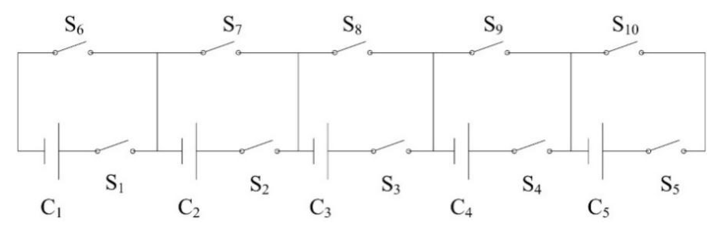
2.1. Short-Circuit Equalization Circuit

As shown in Figure 1, the short-circuit equalization circuit (SCEC) proposed in this article consists of 5 single cells and ten power switches. The lower row of switches are called connection switches (S1–S5), and the upper row of switches are called short-circuit switches (S6–S10). The connection switch and short-circuit switch states corresponding to the same battery are mutually exclusive. Thus, each module of SCEC is composed of a battery and two power switches, which have the advantages of high energy utilization, a simple structure, and robust scalability.

2.2. Equalization Control Strategy

2.2.1. Equalizing Parameter

(1)
Equalization: SOC can reflect the energy change of the battery. This paper selected SOC as the equalization control variable [22,23].
(2)
Equalization judgment threshold: This article compares the maximum difference between the SOC of each battery with the judgment threshold and controls the maximum difference within the judgment threshold. The formula is as follows:
φ = SOC h SOC l ( h = 1 , 2 5 ; l = 1 , 2 5 )    
In the formula, φ is the maximum difference of SOC in the battery group, and S O C h and S O C l are the highest and lowest values of SOC in the battery group, respectively. By comparing the value of φ and α (α is the threshold of equalization judgment), different equalization control strategies are implemented for the battery group according to the results of comparison. This paper chose α = 1% as the threshold of equalization judgment.
(3)
Battery performance parameters: 18650 lithium-ion battery has the advantages of good consistency, mature production technology, and low cost. Therefore, this article is based on the 18650 lithium-ion batteries for research, and its parameters are shown in Table 1.

2.2.2. Charging Control Method

According to the requirements of industrial protections for batteries, the discharge cut-off SOC is 10% and the charge cut-off SOC is 100%. In a 5-battery group, four batteries are charged in series, and the other is used as a balancing battery. During the charging process, when the short-circuit switch is turned on, the connection switch of the battery with the highest energy is turned off, and a balanced battery is replaced to form a new battery group for charging. Thus, all batteries are continuously and alternately reorganized to form a battery group composed of four batteries for charging and a five battery SOC equalization. The charge balance control strategy is shown in Figure 2.
The balance control strategy includes the balanced judgment of the battery group. The specific steps are as follows:
(1)
When a battery’s SOC reaches 100%, and if the number of batteries with 100% SOC is greater than or equal to two, the battery group will stop charging; if there is only one battery with a SOC value of 100%, this battery should be disconnected and other batteries left to continue charging.
(2)
When the SOC value of all batteries is lower than 100%, and if the value of φ is greater than or equal to the threshold α, the balanced battery will replace the battery with the highest SOC value to form a new battery group; if the value of φ is less than 100%, the threshold α is charged in series by the first n batteries.

3. Charging Simulation of AECS

3.1. Simulation Parameters

The feasibility of the equalization circuit and equalization control strategy proposed is verified in Matlab/Simulink. The battery module is used to simulate 18650 lithium-ion batteries. The battery type is set to a lithium-ion battery; the standard working voltage is set to 3.6 V; the rated capacity is set to 3 Ah according to the actual capacity; the initial SOC is set as required; and other parameters are default values. The ideal switch module is used to simulate the power switch, which is turned on under a high-level signal and disconnected under a low-level signal. The controllable current source module is used to control the charging current. In order to reduce the frequency of switching on or off, the Transport Delay module is added, and the delay time is set to 20 s.
The battery group is charged with a constant current at a 1 C charging rate until the voltage of any single battery reaches 4.2 V; 16.8 V is then used for constant voltage charging until the SOC of more than two batteries reaches 100% and charging then stops.

3.2. Simulations under Different Working Conditions

It assumed that the SOC is less than 100% for the five batteries. If this is the case, there are two possible situations:
(1)
When φ is less than the α threshold, the batteries of No.1–No.4 are charged in series, and the No. 5 battery is short-circuited, turning on the switches S1–S4 and S10. This, charges the batteries B1–B4 in series.
(2)
When φ is greater than or equal to the threshold α, its equalization control strategy is shown in Table 2.
According to the above balance control strategy, the initial SOC values of 5 batteries are set to 5%, 10%, 8%, 12% and 15%, respectively. The charging simulation result is shown in Figure 3.
As shown in Figure 3, the SOC values of the five batteries increase until the end of charging. In the charging process, φ is continuously reduced from 10% to 1% and remains stable at around 1%, with the maximum being 1.528%. However, at the end of charging, the SOC values of the five single cells were 99.96%, 99.96%, 99.97%, 99.96%, and 98.97%, respectively, and the φ value was 1%, which proved the feasibility of the charge balance control system. In the constant current charging stage, the charging current is constant at 3A, the time is 20 s, and the change in SOC value in each period is 0.556%. On the other hand, in the constant voltage charging stage, the current value is continuously decreasing, the time value remains unchanged, and the change of the SOC value in each period will decrease.
As shown in the partially enlarged view (a) of Figure 3, the SOC value of battery No.1 rises linearly, while the SOC value of other batteries rises intermittently. The No.1 battery has a low SOC value and has been in a constant current charging state; other batteries have a higher SOC value and alternate recombination charging state. In this state, the single battery with the highest SOC value is disconnected and stops charging, and the SOC value remains unchanged. There is a 20 s delay after each battery group reorganization. Therefore, the change curve of the SOC value shows an intermittent upward trend. As shown in the partially enlarged view (b) in the Figure, the charging mode is changed from constant current charging to constant voltage charging. The charging current changes from a fixed value to an indefinite value, and the SOC value change trend changes accordingly from linear to non-linear. In the constant voltage charging stage, the value of φ decreases because the charging current is constantly getting smaller, but the delay time has not changed.

4. Charging Experiments of AECS

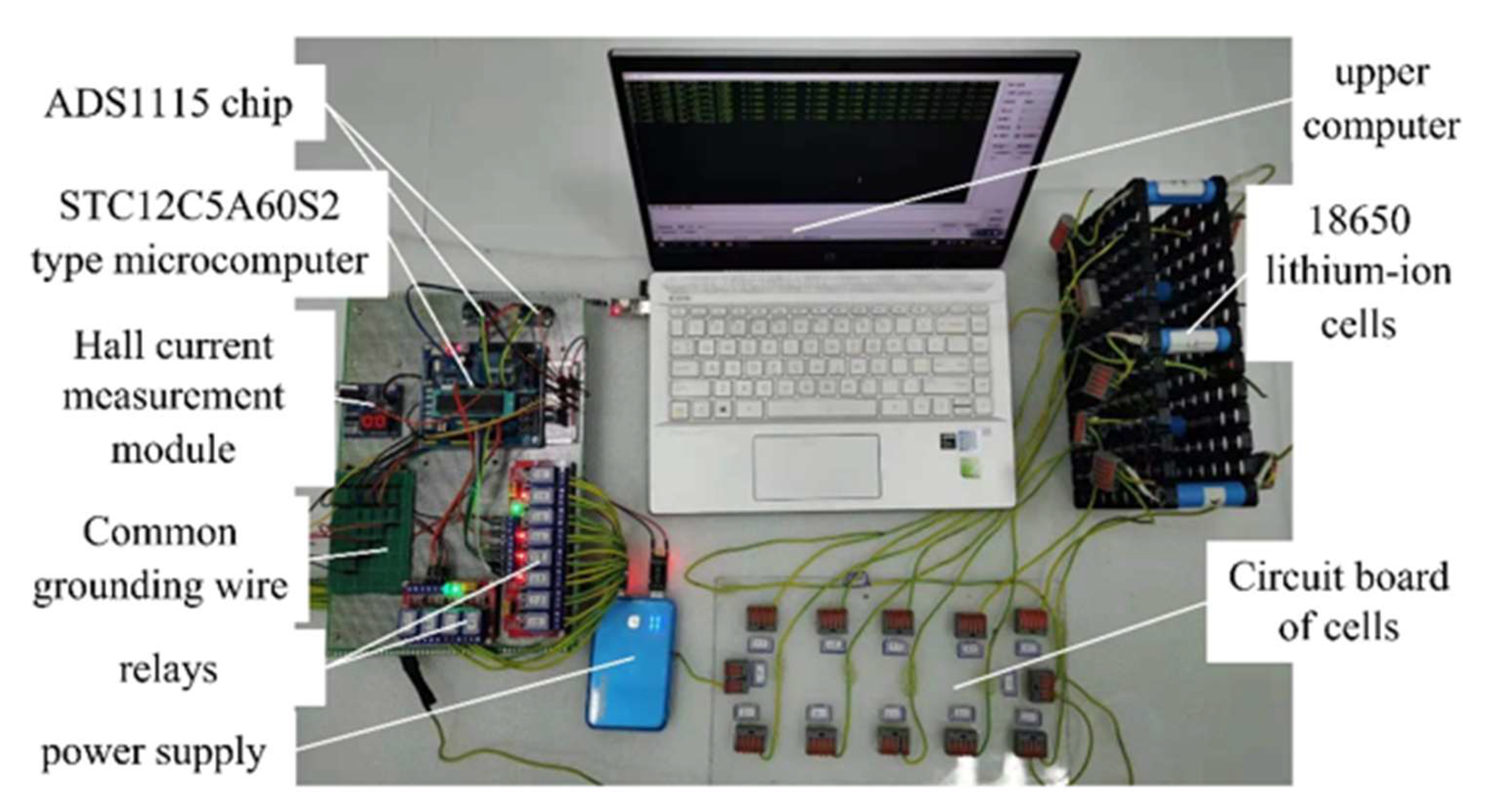
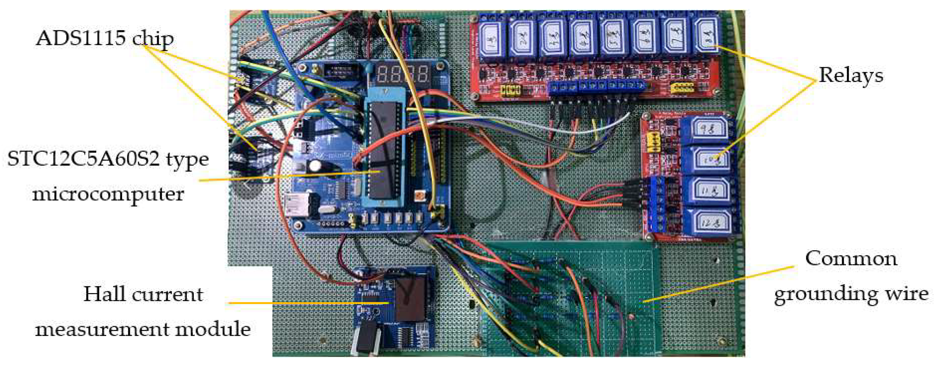
4.1. Experimental Design

The test equipment used includes a charge and discharge tester, host computer charge and discharge tester, and thermostat. The charge and discharge tester is used to charge and discharge the battery group; the host computer monitors and stores the charge and discharge data; and the thermostat simulates the working environment temperature of the battery group.
As shown in Figure 4, AECS is composed of a STC12C5A60S2 series single-chip microcomputer, relay, Hall current measurement module, voltage acquisition chip ADS1115, 18650 lithium-ion battery, power supply, upper computer, and connection harness. The specific hardware structure is shown in Figure 5. Its function is to monitor the battery group’s current and voltage, estimate the SOC of each battery, and judge the conditions of equalization control and data storage.
The best working temperature of the battery used in this study is 25–35 °C. Therefore, all experiments were carried out in an incubator with a temperature set at 25 °C. The experimental steps are as follows:
(1)
According to the SOC and OCV-SOC curves of each battery required for the experiment, the corresponding open-circuit voltage is calculated in Matlab. The OCV- SOC curve is obtained by the test standard of BYD Company.
(2)
Turn on the thermostat and set the temperature to 25 °C. Place all batteries in a thermostat for 2 h and then charge and discharge them until each battery reaches the corresponding open-circuit voltage. Next, connect the AECS circuit and place it in a thermostat for 2 h to stabilize the temperature at 25 °C.
(3)
Download the control program to the STC12C5A60S2 single-chip microcomputer and conduct charge and discharge experiments under different working conditions to verify the feasibility of AECS.
This article regards the data measured by the charge and discharge tester as the accurate data and the data measured by the AECS as the experimental data.

4.2. Experimental Results and Analysis

In order to verify the effectiveness of the designed balance system and control strategy, the experimental design is as follows. Due to the reduction of the current and the delay time, the change of the SOC value during each reorganization period of the battery group will be reduced. Therefore, during the experiment, the delay time is shortened from 20 s to 10 s. The battery group is charged by a constant current and constant voltage charging method. The constant current charging current is 1 C and 0.5 C, and the constant voltage charging voltage is 16.8 V. When the voltage value of any battery reaches 4.2 V, constant current charging is converted to constant voltage charging. The charge cut-off condition is that the SOC of 2 or more batteries is greater than or equal to 100%. The initial SOC of the five batteries are 14.6%, 13%, 8.6%, 9.7%, and 6.0%, respectively.

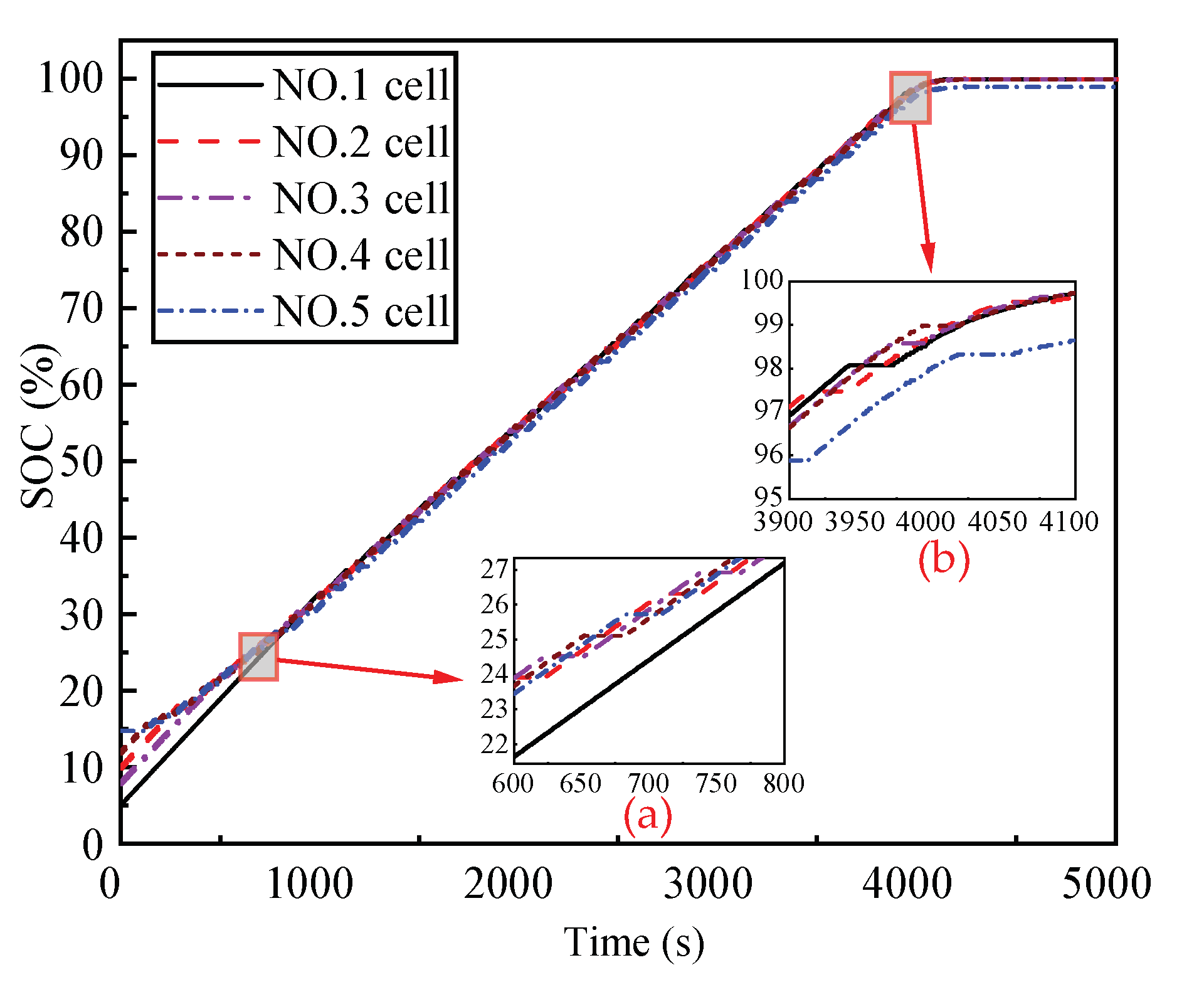
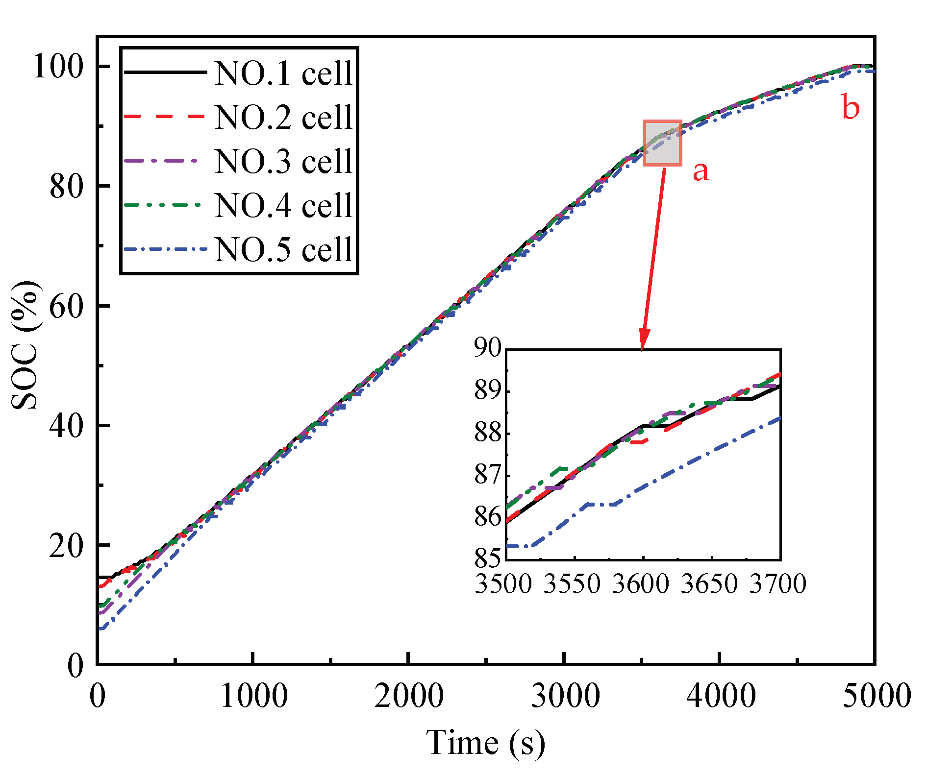
4.2.1. 1 C Charging Rate with the 20 s Delay Time Charging Experiment

According to the charge balance control strategy proposed in this paper, the experimental results of charging equalization at 1 C charge rate with the 20 s delay time are shown in Figure 6.
As shown in Figure 6, during the charging process, the 5-cell SOC increases intermittently. At the end of charging, the SOC is 100%, 100%, 100%, 100%, and 99.2%, respectively, and the φ value is 0.8%. The rising rate of SOC before point a is greater than the rising rate of SOC from point a to point b, and the rising rate of SOC at point b is zero. At point a, the charging mode changes from constant current charging to constant voltage charging, and the charging current is decreasing. Before point a, the maximum value of φ when the battery group reaches an equalization state is 1.542%. After point a, the maximum value of φ is 1.214%. This shows that reducing the current value can reduce the value of φ and improve the equalization effect of the equalization control system.

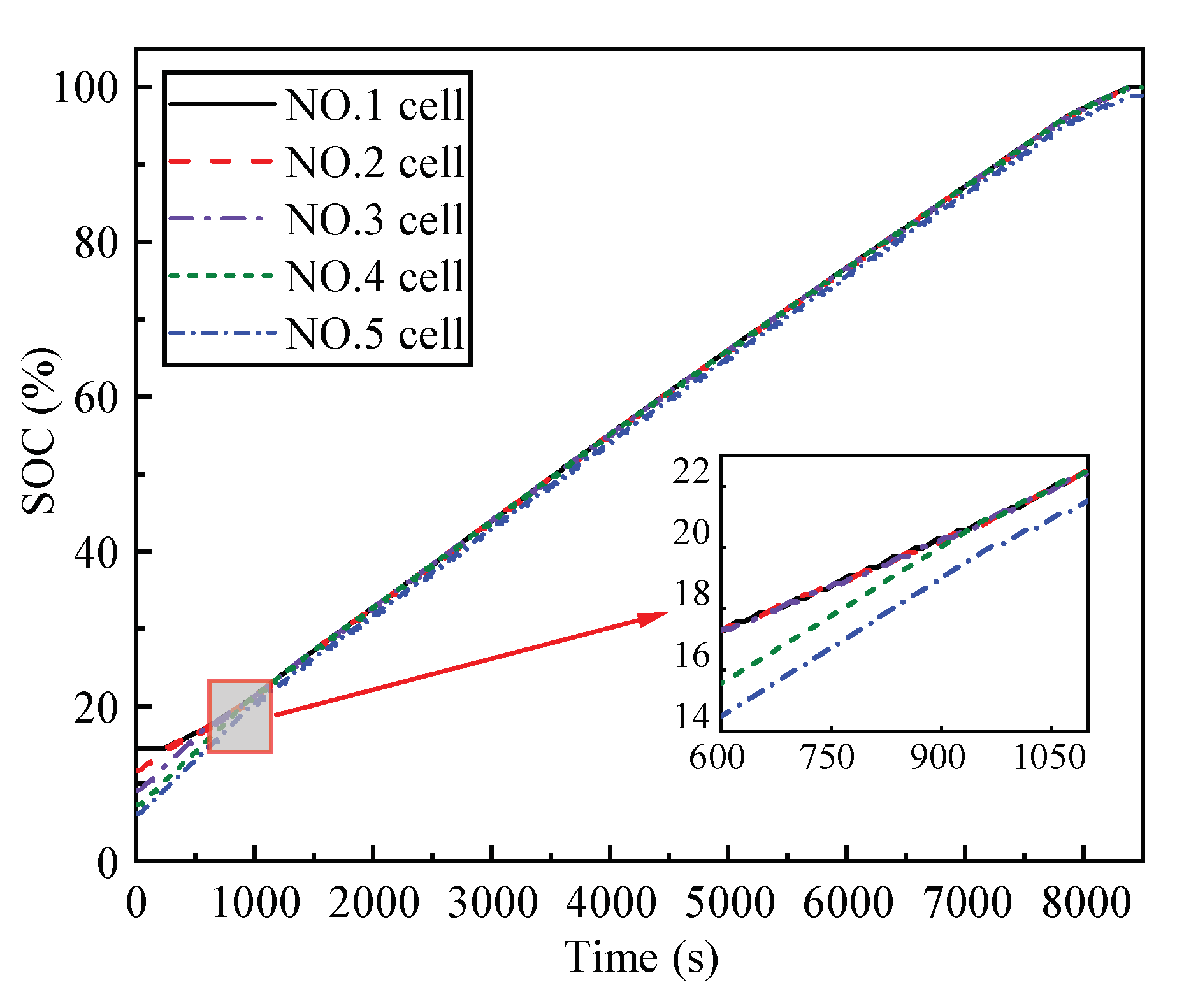
4.2.2. 0.5 C Charging Rate with the 20 s Delay Time Charging Experiment

Experiments with different charging rates were set, and the charging rate was reduced from 1 C to 0.5 C, and the delay time remained unchanged. The experimental results of charging equalization at a 0.5 C charging rate with the 20 s delay time are shown in Figure 7.
As shown in Figure 7, during the charging process, the 5-cell SOC increases intermittently. At the end of charging, the SOC is 100%, 100%, 100%, 99.9%, and 98.9%, respectively, and φ is 1.1%. The maximum SOC difference of the battery group when it reaches an equalization state is 1.288%. Compared with the 1C charging rate of the 20 s delay time, the maximum SOC difference of 0.5 C charging rate of the 20 s delay time is smaller when the system reaches an equalization state. The result shows that reducing the charging rate can effectively improve the equalization effect.

4.2.3. 0.5 C Charging Rate with 10 s Delay Time Charging Experiment

Experiments with different delay times were set. The delay time was reduced from 20 s to 10 s while the charging rate remained unchanged. The experimental results of charging equalization at 0.5 C charging rate with the 10 s delay time are shown in Figure 8.
As shown in Figure 8, during the charging process, the 5-cell SOC increases intermittently. At the end of charging, the SOC is 100%, 100%, 100%, 100%, and 99%, respectively, and φ is 1%. The maximum SOC difference of the battery group when it reaches the equalization state is 1.035%. Compared with the 20 s delay time 0.5 C charging rate, the 10 s delay time 0.5 C charging rate has a minor maximum SOC difference when reaching equalization. The result can effectively improve the balance by reducing the delay time with the same charging rate effect.

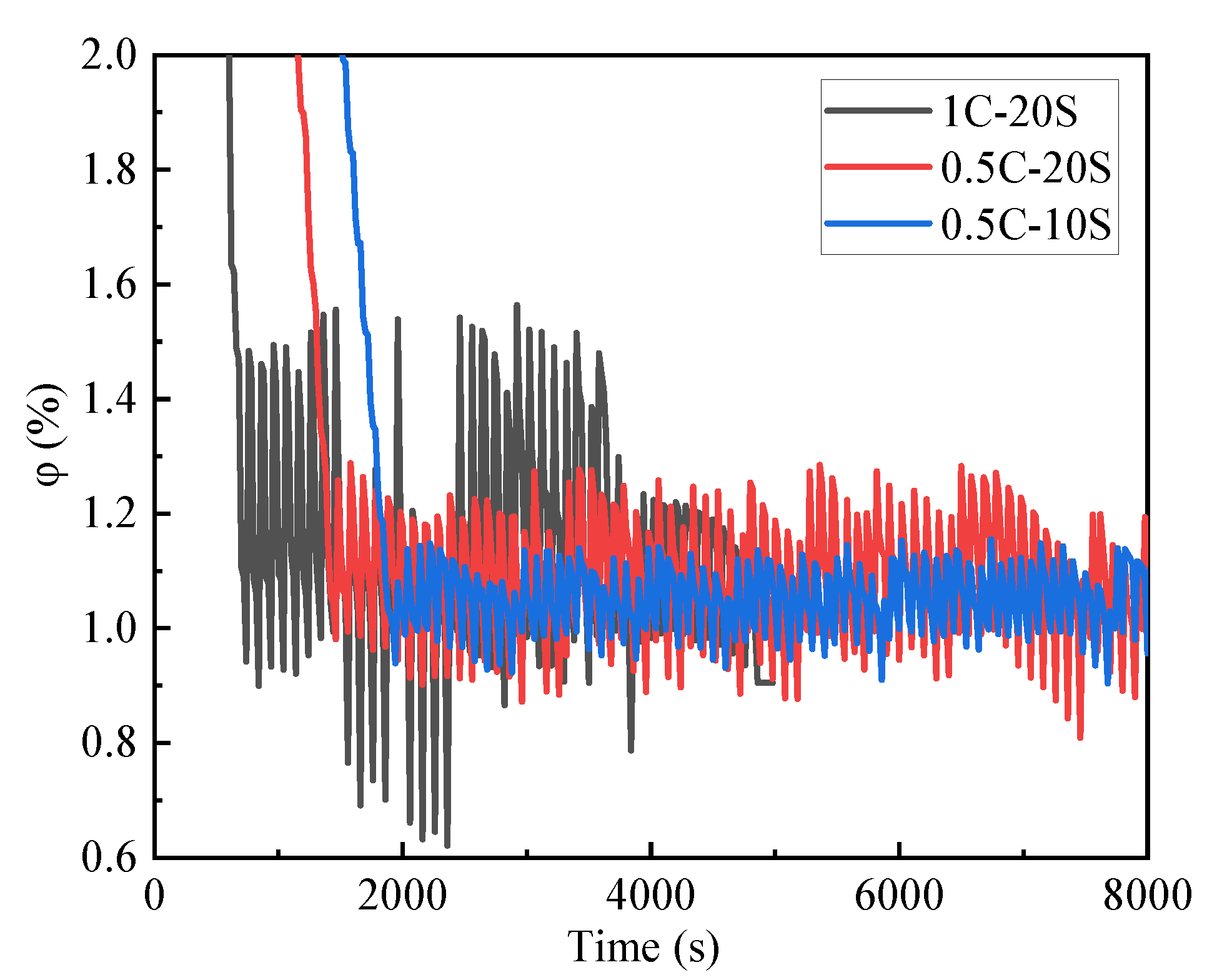
4.3. Comparison of the SOC Difference under Different Working Conditions

The overall SOC difference was analyzed and compared under three other charging conditions, comparing the results as shown in Figure 9.
It can be seen from the figure that the overall SOC difference under the three different charging conditions is gradually reduced from the original SOC difference of the battery group to about 1%. According to the control strategy proposed in this paper, batteries are constantly alternately reorganized into a new battery group for charging, so that the overall SOC difference of the battery group is continuously decreasing, thus verifying the effectiveness of the equalization system. It can be seen from the figure that the charging rate is reduced from 1 C to 0.5 C while charging, while other conditions remain unchanged. When the battery group reaches the equalization state of charge, the overall SOC difference of the 0.5 C charging rate is significantly smaller than the 1 C charging rate SOC difference. It shows that reducing the charging current can effectively improve the equalization effect. Secondly, the overall SOC difference of the 10 s delay time is smaller than the SOC difference of the 20 s delay time when the delay time is reduced from 20 s to 10 s, and other conditions remain the same. The results indicate that the equalization effect can be effectively improved by reducing the delay time when other conditions remain unchanged during the charging process.

5. Conclusions

This paper proposes a short-circuit equalization circuit and its control strategy based on 18650 ternary lithium-ion batteries and constructs the AECS topology. Through simulation analysis and experimental verification, the balance control of the battery in the lithium-ion battery group is studied. The main conclusions are as follows:
(1)
An ACES topology and its charging control strategy were proposed, its working principle and advantages were studied, and a charging simulation was carried out in Matlab/Simulink. A battery group consisting of five batteries with the initial SOC value of 5%, 10%, 8%, 12% and 15% was charged. The simulation results show that during the charging process, the maximum SOC difference of the battery group is continuously reduced from 10% to 1%, which proves the feasibility of the charging control strategy.
(2)
A charging experiment of the battery group was carried out. In the charging experiment, the SOC difference in the constant current charging stage dropped from 8.6% to about 1%, and the maximum SOC difference was 1.542%. In the constant voltage charging stage, the maximum difference in SOC dropped from 1.542% to 1.214% due to the decrease of the charging current. The maximum difference of SOC at the end of charging was 0.8%, which indicated that the alternating balance control system designed in this paper could realize the charging balance of the battery group.
(3)
A charging experiment with a 0.5 C charging rate with the 20 s delay time was set. In the experiment, the maximum SOC difference of the battery group when it reached the equalization state was 1.288%. The result showed that, compared to the charging experiment at 1 C charging rate, the equalization effect could be effectively improved when the charging rate was low.
(4)
A charging experiment at a 0.5 C charging rate with the 10 s delay time was set. In the experiment, the maximum SOC difference of the battery group when it reached the equalization state was 1.035%. The results showed that when the charging rate did not change, reducing the delay time could effectively improve the equalization effect of the equalization system.

Author Contributions

Conceptualization, C.Z. and Y.L.; methodology, C.Z. and Y.L.; software, Z.X.; validation, Y.L, J.H. and J.L.; formal analysis, Y.L.; investigation, C.Z.; resources, C.Z.; data curation, Z.X.; writing—original draft preparation, Y.L.; writing—review and editing, Y.L. and J.H.; visualization, C.Z.; supervision, C.Z.; project administration, C.Z.; funding acquisition, C.Z. All authors have read and agreed to the published version of the manuscript.

Funding

This research was funded by the National Natural Science Foundation of China: Research on the Integrated Control Method of the Lateral Stability of Distributed Drive Mining Electric Vehicles (51974229) and the 2021 Youth Innovation Team Construction Scientific Research Program of Shaanxi Provincial Education Department (Project No.21JP071).

Institutional Review Board Statement

Not applicable.

Informed Consent Statement

Not applicable.

Data Availability Statement

Not applicable.

Conflicts of Interest

The authors declare no conflict of interest.

References

  1. Widmaier, M.; Jäckel, N.; Zeiger, M.; Abuzarli, M.; Engel, C.; Bommer, L.; Presser, V. Influence of carbon distribution on the electrochemical performance and stability of lithium titanate based energy storage devices. Electrochim. Acta 2017, 247, 1006–1018. [Google Scholar] [CrossRef]
  2. Chen, G.W.; Liu, Z.T.; Su, H.; Zhuang, W.C. Electrochemical-distributed thermal coupled model-based state of charge estimation for cylindrical lithium-ion batteries. Control Eng. Pract. 2021, 109, 1006–1018. [Google Scholar] [CrossRef]
  3. Wang, X.M.; Xie, Y.Q.; Day, R.; Wu, H.; Hu, Z.L.; Zhu, J.Q.; Wen, D. Performance analysis of a novel thermal management system with composite phase change material for a lithium-ion battery pack. Energy 2018, 156, 154–168. [Google Scholar] [CrossRef] [Green Version]
  4. Gozdur, R.; Guzowski, B.; Dimitrova, Z.; Noury, A.; Mitukiewicz, G.; Batory, D. An energy balance evaluation in lithium-ion battery module under high temperature operation. Energy Convers. Manag. 2021, 227, 113565. [Google Scholar] [CrossRef]
  5. Diao, W.P.; Xue, N.N.; Bhattacharjee, V.; Jiang, J.C.; Karabasoglu, O.; Pecht, M. Active battery cell equalization based on residual available energy maximization. Appl. Energy 2018, 210, 690–698. [Google Scholar] [CrossRef]
  6. Cui, X.D.; Shen, W.; Zhang, Y.L.; Hu, C.G.; Zheng, J.C. Novel active LiFePO4 battery balancing method based on chargeable and dischargeable capacity. Comput. Chem. Eng. 2017, 97, 27–35. [Google Scholar] [CrossRef]
  7. Samanta, A.; Chowdhuri, S. Active Cell Balancing of Lithium-ion Battery Pack Using Dual DC-DC Converter and Auxiliary Lead-acid Battery. J. Energy Storage 2020, 33, 102109. [Google Scholar] [CrossRef]
  8. Wu, T.Z.; Ji, F.; Liao, L.; Chun, C. Voltage-SOC balancing control scheme for series-connected lithium-ion battery packs. J. Energy Storage 2019, 25, 100895. [Google Scholar] [CrossRef]
  9. Dam, S.K.; John, V. A Modular Fast Cell-to-Cell Battery Voltage Equalizer. IEEE Trans. Power Electron. 2020, 35, 9445–9463. [Google Scholar] [CrossRef]
  10. Ding, X.; Zhang, D.H.; Cheng, J.W.; Wang, B.B.; Chai, Y.M.; Zhao, Z.; Xiong, R.; Luk, P.C. A Novel Active Equalization Topology for Series-Connected Lithium-ion Battery Packs. IEEE Trans. Ind. Appl. 2020, 56, 6892–6903. [Google Scholar] [CrossRef]
  11. Shang, Y.L.; Zhang, Q.; Cui, N.X.; Duan, B.; Zhang, C.H. An Optimized Mesh-Structured Switched-Capacitor Equalizer for Lithium-Ion Battery Strings. IEEE Trans. Transp. Electrif. 2019, 5, 252–261. [Google Scholar] [CrossRef]
  12. Singirikonda, S.; Obulesu, Y. Active cell voltage balancing of Electric vehicle batteries by using an optimized switched capacitor strategy. J. Energy Storage 2021, 38, 102521. [Google Scholar] [CrossRef]
  13. Chen, Y.; Liu, X.F.; Shen, T.; Cheng, L.F.; Xiaogang, W.; Yang, R.; Yang, S.Y. An any-cell(s)-to-cell(s) equalization method with a single magnetic component for Lithium-ion battery pack. J. Energy Storage 2020, 33, 102071. [Google Scholar] [CrossRef]
  14. Zhang, K.; Sun, L.; Fan, S.G. Research on design methodology of super capacitor balancing system based on multi-winding transformer. Power Electron. 2018, 52, 37–40. [Google Scholar] [CrossRef]
  15. Li, Y.; Xu, J.H.; Mei, X.; Wang, J.P. A Unitized Multiwinding Transformer-Based Equalization Method for Series-Connected Battery Strings. IEEE Trans. Power Electron. 2019, 34, 11981–11989. [Google Scholar] [CrossRef]
  16. Liu, W.; Tang, C.Y.; Wang, T.R.; Na, W.; Sun, J.L. Research on Active Equalization Topology and Control Strategy of Series Battery Pack. J. Power Supply 2020, 1–14. [Google Scholar]
  17. Gao, M.Y.; Qu, J.F.; Lan, H.; Wu, Q.X.; Lin, H.P.; Dong, Z.K.; Zhang, W.Z. An Active and Passive Hybrid Battery Equalization Strategy Used in Group and between Groups. Electronics 2020, 9, 1744. [Google Scholar] [CrossRef]
  18. Shang, Y.L.; Zhao, S.F.; Fu, Y.H.; Han, B.; Hu, P.P.; Mi, C. A Lithium-Ion Battery Balancing Circuit Based on Synchronous Rectification. IEEE Trans. Power Electron. 2020, 35, 1637–1648. [Google Scholar] [CrossRef]
  19. Liu, H.R.; Du, C.F.; Chen, S.L.; Li, Y.Z.; Xia, C.Y. Research on Bidirectional Battery Group Equalizer with Double Deck Based on Cuk Chopper Circuit. J. Power Supply 2017, 15, 142–147. [Google Scholar]
  20. Liu, Y.; Xia, C.Y.; Gu, M.; Xin, W.; Men, X.M. A novel active equalizer for Li-ion battery pack in electric vehicles. Energy Procedia 2019, 158, 2649–2654. [Google Scholar] [CrossRef]
  21. Hua, Y.; Zhou, S.D.; Cui, H.G.; Liu, X.H.; Zhang, C.; Xu, X.; Ling, H.P.; Yang, S.C. A comprehensive review on inconsistency and equalization technology of lithium-ion battery for electric vehicles. Int. J. Energy Res. 2020, 44, 11059–11087. [Google Scholar] [CrossRef]
  22. Moon, S.; Kim, J. Balanced charging strategies for electric vehicles on power systems. Appl. Energy 2017, 189, 44–54. [Google Scholar] [CrossRef]
  23. Turksoy, A.; Teke, A.; Alkaya, A. A comprehensive overview of the dc-dc converter-based battery charge balancing methods in electric vehicles. Renew. Sustain. Energy Rev. 2020, 133, 110274. [Google Scholar] [CrossRef]
Figure 1. The short-circuit equalization of n is 4.
Wevj 12 00114 g001
Figure 2. Process of charging equalization control strategy. Y=Yes. N=No.
Wevj 12 00114 g002
Figure 3. Simulation results of charging equalization. (a) and (b) are partial enlargements.
Wevj 12 00114 g003
Figure 4. The experimental platform of AECS.
Wevj 12 00114 g004
Figure 5. The main hardware structure of AECS.
Wevj 12 00114 g005
Figure 6. 1 C charging rate with the 20 s delay time charging experimental equalization result. a: Charge mode changes from constant current charge to constant voltage charge. b: End of charging.
Wevj 12 00114 g006
Figure 7. 0.5 C charging rate with the 20 s delay time charging experimental equalization result.
Wevj 12 00114 g007
Figure 8. 0.5 C charging rate with 10 s delay time charging experimental equalization result.
Wevj 12 00114 g008
Figure 9. Comparison of the SOC difference under different working conditions.
Wevj 12 00114 g009
Table 1. Basic parameters of 18650 lithium-ion cell.
OrderName of ParameterValue and Unit
1Size ϕ   = 18.00 mm
H = 65.00 mm
2Rated Capacity2.55 Ah
3Practical Capacity3.0 Ah
4Working Voltage3.6 V
5Charging Cut-Off Voltage4.2 V
6Discharging Cut-Off Voltage2.5 V
7Maximum Continuous Discharge Rate3 C
8Optimum Working Temperature 25   ~   35 °C
9Working Temperature Range 20   ~   60 °C
Table 2. Charge equalization control strategy when φ is greater than or equal to α.
The Battery with the Highest SOCClosed SwitchesCharging Cells in Series
B1S2,S3,S4,S5,S6B2,B3,B4,B5
B2S1,S3,S4,S5,S7B1,B3,B4,B5
B3S1,S2,S4,S5,S8B1,B2,B4,B5
B4S1,S2,S3,S5,S9B1,B2,B3,B5
B5S1,S2,S3,S4,S10B1,B2,B3,B4
Publisher’s Note: MDPI stays neutral with regard to jurisdictional claims in published maps and institutional affiliations.

