Article

Evaluation of the Magnetic Field Leakage from Two Wireless Power Transfer Systems for EV/PHV Driven Simultaneously

TOYOTA Central R&D Inc., 41-1, Yokomichi, Nagakute, Aichi 480-1192, Japan
*
Author to whom correspondence should be addressed.
World Electr. Veh. J. 2019, 10(2), 41; https://doi.org/10.3390/wevj10020041
Submission received: 21 May 2019 / Revised: 8 June 2019 / Accepted: 10 June 2019 / Published: 13 June 2019

Abstract

:
Wireless power transfer for electric and plug-in hybrid vehicles has been developed to facilitate battery charging. In a wireless power transfer system, because the magnetic field leaks to the surroundings of the vehicle, it is important to evaluate the quantitative human exposure. The International Commission on Non-Ionizing Radiation Protection provides guidelines for human exposure assessment. In this study, we evaluate the magnetic field leakage under two parking configurations and current phase differences for two vehicles being simultaneously charged (3.7 kW at 85 kHz per vehicle). The results of the analysis show that the magnetic field leakage is lower than the reference level of the guidelines for all cases and that the leakage could be reduced by controlling the phase difference between the two wireless power transfer systems equally distributed from the single high-frequency power source for each parking configuration.

1. Introduction

To mitigate environmental problems such as global warming and air pollution, electric vehicles (EVs) and plug-in hybrid vehicles (PHVs), which have lower CO2 emissions compared to conventional gasoline vehicles, have been developed. Wireless power transfer (WPT), which can conveniently charge batteries, is being developed to popularize such vehicles. Among the various methods for WPT [1,2,3,4,5], magnetic resonance coupling is most commonly used for EV and PHV charging due to its high transmission power and long-distance transmission. However, when a large amount of power is transmitted using this method, there is concern that exposure to the magnetic field leakage may affect the human body. In the guidelines [6] on human body protection against electromagnetic field exposure established by the International Commission on Non-Ionizing Radiation Protection (ICNIRP), a physical quantity called basic restriction is defined as an evaluation standard for safety. It is desirable to design systems that do not exceed this standard. The induced electric field is used as the physical quantity that defines the basic restriction for exposure to a magnetic field in the frequency band considered for use in WPT systems. The induced electric fields in WPT systems have been analyzed [7,8,9,10]. In one study [7,8], the induced electric field was analyzed in various situations, such as when a person is standing upright beside an EV or picking up an object from the ground during wireless charging. It was found that the induced electric field was below the basic restriction. In another study [9], the exposure to the induced electric field for a person standing upright beside an EV was analyzed with the mounting position of the secondary coil as a parameter. The induced electric field was largest when the secondary coil was mounted at the center of an EV. The induced electric field has also been analyzed for various gap sizes between the primary and secondary coils [10]. It was found that the induced electric field decreased with increasing gap size. In these evaluations, it was assumed that power was transmitted to only one vehicle. However, with the spread of WPT, it is expected that multiple vehicles would be charged at the same time in a commercial facility. In this paper, we consider the simultaneous charging of two vehicles from a single power source. We examine how the parking configuration of the two vehicles and the current phase difference between coils affect magnetic field leakage.

2. Analysis Method and Conditions

2.1. Outline of Analysis Method

For the analysis of the induced electric field in the body, a two-step analysis method, which independently calculates the magnetic field distribution and the induced electric field, was used. In the first step, the magnetic field leakage around the WPT system was calculated using a commercially available electromagnetic simulator, and a vector potential was calculated from the result. In the second step, the induced electric field was calculated from the vector potential obtained in the first step using the scalar-potential finite difference method [11]. The scholar potencial finite difference (SPFD) method is a calculation method based on a quasi-static approximation, which calculates without considering the electric field induced by the fluctuating magnetic field and the magnetic field caused by a sufficiently small induced current.
For analyzing the in-body induced electric field, the ICNIRP guidelines recommend using a numerical human body model created with cells made of 2-mm squares (voxels) for muscles and fat [6]. In this analysis, we used whole-body voxel human model named TARO, developed by the National Institute of Information and Communications Technology, and the average body size of a Japanese adult male [12]. In this model, the human body occupied a space of 640 × 320 × 1732 mm; this space was divided into 2 mm voxels; and each voxel was distinguished by material flags, such as skin, blood vessels, and organs. The physical properties such as conductivity and relative permittivity for each of these flags are given by Gabriel et al. [13]. The high frequency electromagnetic field simulator named HFSSTM [14] using the finite element method was used for the first step, and our original code was used for the second step.

2.2. Analysis Conditions

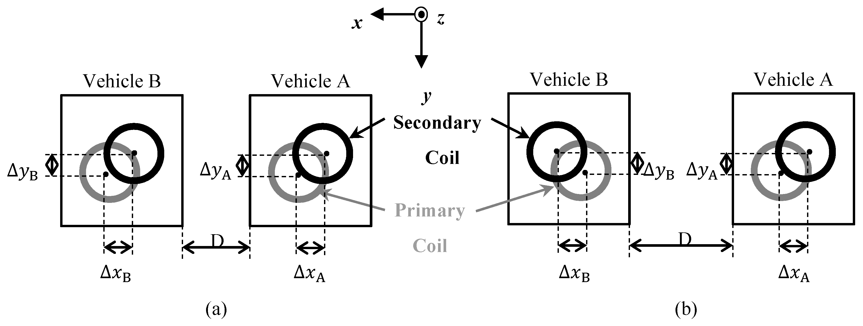
In this evaluation, we analyzed the magnetic field leakage between two vehicles that were charged simultaneously using a single power supply. Figure 1 shows an overview and the coordinate system for the vehicle model used in this analysis. The shapes of the vehicles, primary coils, and secondary coils were the same for both vehicles. The vehicles equipped with secondary coils represent ordinary passenger cars (size shown in Figure 1). The secondary coil was mounted at the center bottom of the vehicle, and the primary coil was installed on the floor below it. The floor was a conductor, which previous studies have found to be the worst case [9]. The primary and secondary coils were both circular, and their sizes were the same as those in a previous study [9,10]. The gap size (z-direction) between the coils was 150 mm. Two configurations were set assuming that the positional relationship between the two vehicles depends on their parking positions. Figure 2 shows the positional relationship between the primary and secondary coils of the two vehicles for the two configurations. Misalignments in the x- and y-directions of the secondary coil center from the primary coil center are denoted as ΔxA,B and ΔyA,B, respectively. For vehicle A, ΔxA = −100 mm and ΔyA = −75 mm for both configurations; for vehicle B, ΔxB = −100 mm and ΔyB = −75 mm for configuration 1, and ΔxB = 100 mm and ΔyB = −75 mm for configuration 2. The center-to-center distance between the primary coils of the two vehicles was fixed at 2500 mm for both parking configurations. The distance between the secondary coils was 2500 mm for configuration 1 and 2700 mm for configuration 2. The distance between the sides of vehicles A and B was 800 mm for configuration 1 and 1000 mm for configuration 2.
When the shapes of the primary and secondary coils are the same, as in this analysis, the absolute values of the primary current I1 and the secondary current I2 when transmitting power P are given by Equation (1) [9,10]; the phase relationship is expressed by Equation (2) [10]:
| I 1 A , B | P 2 π f k L s 1 , | I 2 A , B | P 2 π f k L s 2 ,
I 2 A , B j I 1 A , B .
Here, the subscripts A and B for I1 and I2 indicate the values for vehicles A and B, respectively. The parameters Ls1, Ls2, and k in Equation (1) are the self-inductance of the primary coil, that of the secondary coil, and the coupling coefficient between the coils, respectively. P and f are the transmission power and transmission frequency, respectively; f was 85 kHz and P was 3.7 kW. The currents in the primary and secondary coils of vehicle A are denoted as I1A and I2A, and those of vehicle B are denoted as I1B and I2B, respectively. The currents, obtained using a previously reported method [9,10], are |I1A| = |I2A| = |I1B| = |I2B| = 20.3 A. Equation (2) indicates that the phase of I2A,B is delayed by 90° compared to that of I1A,B.
When the two adjacent vehicles were charged simultaneously, the magnetic field leakage distribution around the WPT system changed due to the change in the phase difference between the current of vehicle A and that of vehicle B. The magnetic field leakage was analyzed with a phase difference θ of 0° and 180°. In this analysis, it was assumed that a human was standing between vehicles A and B at a position 200 mm away from vehicle A, as shown in Figure 3. The magnetic field analysis region is a rectangular parallelepiped with dimensions of 400 mm × 700 mm × 800 mm (x × y × z), which was set to surround the human. The average magnetic field strength in this region was analyzed.

3. Results and Discussion

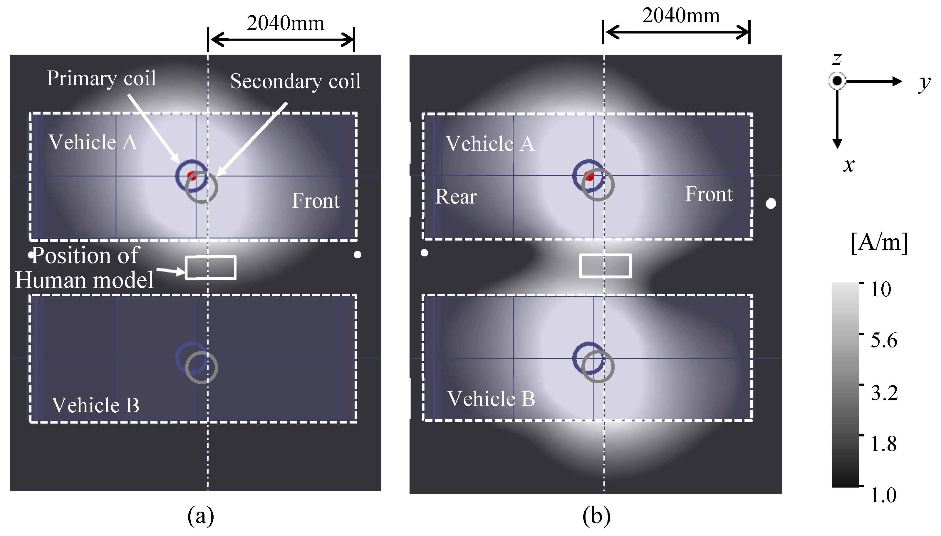
The magnetic field distributions in the middle position (height from floor: 120 mm) in the gap between the primary and secondary coils where only vehicle A is charged and where both vehicles are charged are shown in Figure 4a,b, respectively. The solid rectangle between the two vehicles is the cross section of the analysis region. In both cases, the magnetic field strength increases around the side of the coil. When the two vehicles are simultaneously charged, the strong magnetic field region is enlarged.
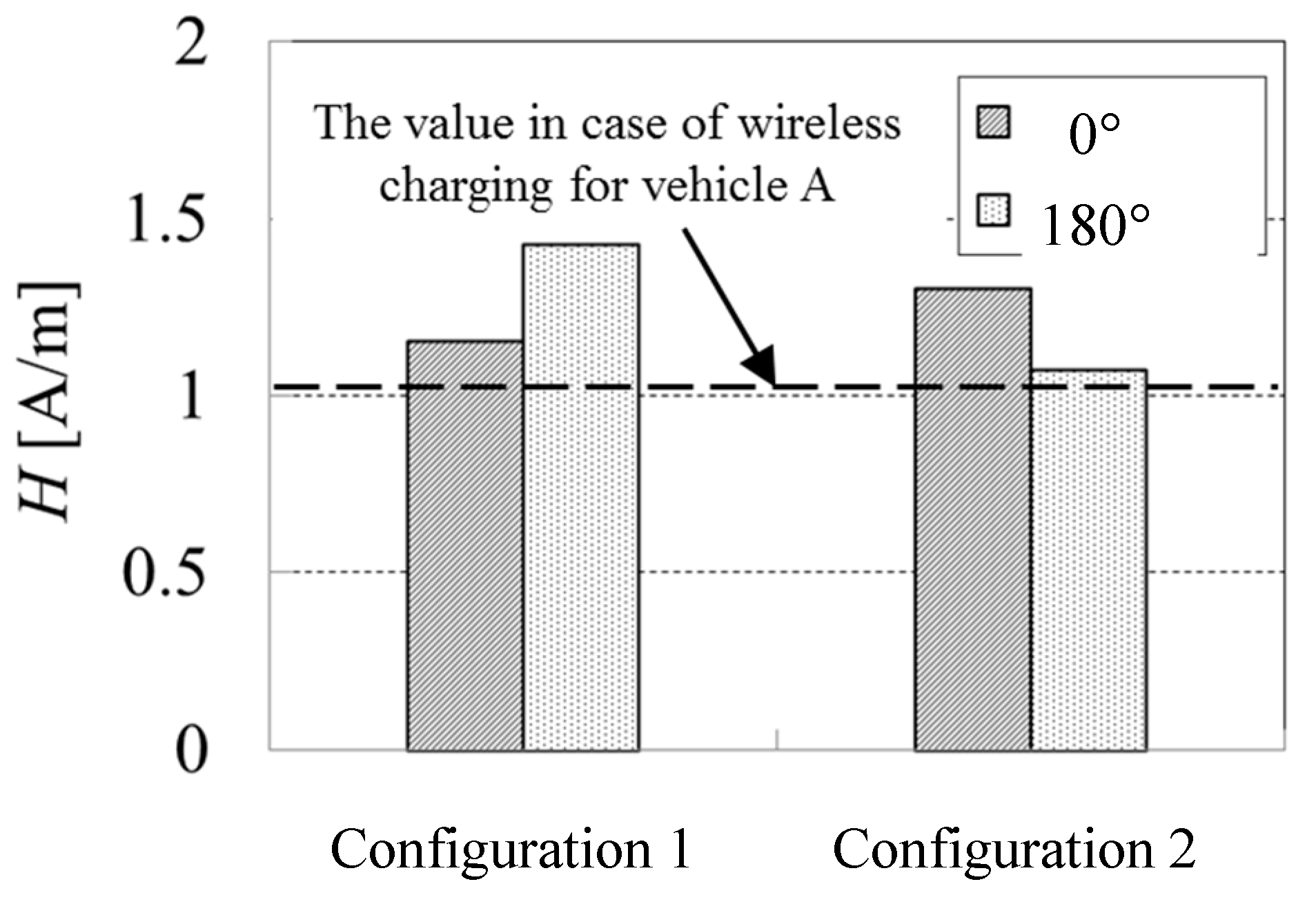
The average magnetic field strength H in the analysis region defined in the previous section is shown in Figure 5. The bars show the magnetic field strength for the two vehicles being charged simultaneously, and the broken line shows that for only vehicle A being charged. For only one vehicle being charged, H is 1.00 A/m. For the simultaneous charging of two vehicles, H is 1.15 and 1.43 A/m for phase differences θ of 0° and 180° for configuration 1, respectively. The increase in the magnetic field strength is larger for the antiphase configuration (θ = 180°). H is 1.31 and 1.08 A/m for phase differences θ of 0° and 180° for configuration 2, respectively. The increase in the magnetic field strength is larger for the in-phase configuration (θ = 0°). For all conditions, the magnetic field strength is at most 1/14 of the reference level defined in the ICNIRP guidelines (21 A/m) [6].
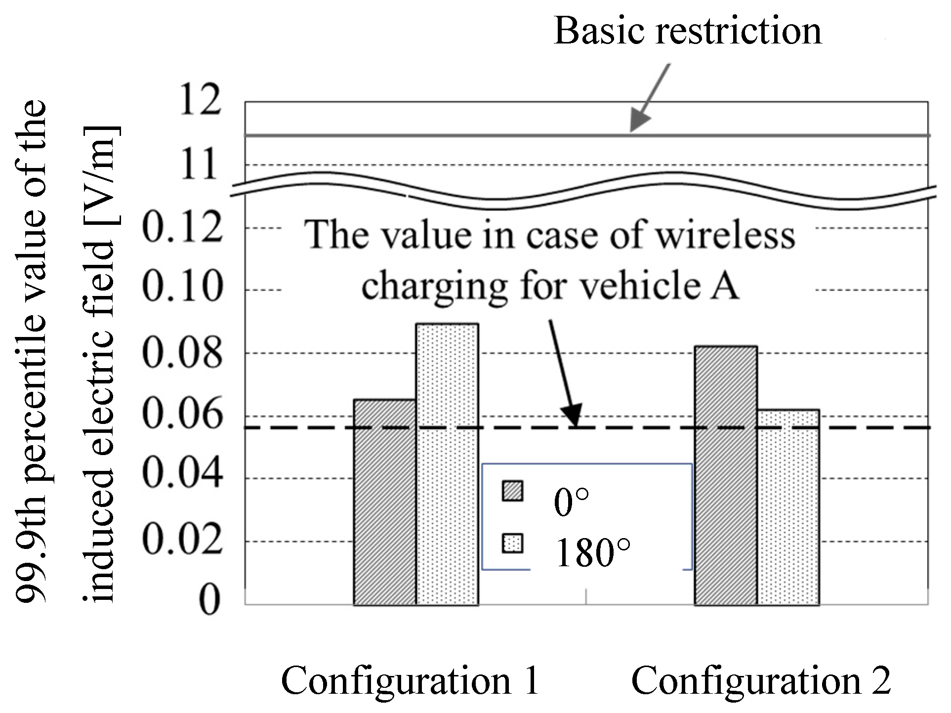
The computed results for the induced electric field 99.9th percentile value of Ein in the human model are shown in Figure 6. Here, the broken line is the induced electric field when only vehicle A is charged. In this case, Ein is 0.055 V/m. For the simultaneous charging of two vehicles, Ein is 0.066 and 0.089 V/m for phase differences θ of 0° and 180° for configuration 1, respectively. The increase of the magnetic field strength is larger in the antiphase configuration (θ = 180°). Ein is 0.082 and 0.062 V/m for phase differences θ of 0° and 180° for configuration 2, respectively. The increase in the magnetic field strength is larger for the in-phase configuration (θ = 0°). For all conditions, the induced electric field 99.9th percentile value is at most 1/100 of the basic restriction defined in the ICNIRP guidelines (11.475 V/m) [6]. The magnetic field strength H shown in Figure 5 and the induced electric field strength 99.9th percentile value shown in Figure 6 show the same trends for the effects of parking configuration and phase difference θ.
These results indicate that the effects of different conditions can be understood by analyzing the magnetic field distribution in detail.
Spatially averaged values |Hx|, |Hy|, and |Hz| of the x, y, and z components in the analysis region, expressed in Equation (3), were obtained:
H = | H x | 2 + | H y | 2 + | H z | 2
|Hx|, |Hy|, and |Hz| are shown in Figure 7a,b. For configuration 1, |Hx|= 0.97 A/m and H = 1.15 A/m at θ = 0°, and, thus, the |Hx| component is dominant. |Hz| = 1.39 A/m and H = 1.43 A/m for θ = 180°, and, thus, the |Hz| component is dominant. This is because the x and z components of the magnetic field leakage vectors for vehicles A and B strengthen and weaken each other, respectively, at θ = 0. Because the direction of the magnetic field vector for vehicle B is reversed, the x component is weakened and the z component is strengthened at θ = 180°.
For configuration 2, |Hz| = 1.26 A/m and H = 1.31 A/m at θ = 0°, and, thus, the |Hz| component is dominant. |Hz| = 1.05 A/m and H = 1.08 A/m at θ = 180°, and, thus, the |Hz| component is dominant. This is because the x and z components of the magnetic field leakage vectors for vehicles A and B weaken and strengthen each other, respectively, at θ = 0°. Because the direction of the magnetic field vector of vehicle B is reversed, the x component is strengthened and the z component is weakened at θ = 180°. Therefore, the strength of the induced electric field in the human body depends on the distribution of the magnetic field component during exposure to the non-uniform magnetic field leakage from the WPT system.

4. Conclusions

We analyzed the magnetic field leakage generated around a WPT system for two vehicles charged simultaneously using one power source. It was found that the magnetic field strength in the case of simultaneously charging two vehicles was less than 1.5 times that in the case of one vehicle charging and was lower than the reference level given in the ICNIRP guidelines. It was also found that the leaked magnetic field strength can be reduced by changing the phase difference θ between the two systems. Furthermore, it was found that when the human body is exposed to the non-uniform magnetic field leakage around this system, the magnitude of the internal induced electric field depends on the intensity distribution of the magnetic field component.

Author Contributions

Conceptualization, investigation, validation, writing (original draft), and visualization: T.W. Conceptualization, investigation, data curation, and writing (review and editing): Y.H.

Funding

This research received no external funding.

Acknowledgments

The authors would like to thank the two anonymous reviewers whose comments helped us improve our manuscript.

Conflicts of Interest

The authors declare no conflicts of interest.

References

  1. Kurs, A.; Karalis, A.; Moffatt, R.; Joannopoulos, J.D.; Fisher, P.; Soliačić, M. Wireless power transfer via strongly coupled magnetic resonances. Sci. Express 2007, 317, 83–86. [Google Scholar] [CrossRef] [PubMed]
  2. Imura, T.; Uchida, T.; Hori, Y. Basic experimental study on helical antennas of contactless power transfer for electric vehicles by using magnetic resonant couplings. In Proceedings of the 2009 IEEE Vehicle Power and Propulsion Conference, Dearborn, MI, USA, 7–10 September 2009; pp. 936–940. [Google Scholar] [CrossRef]
  3. Bushia, M.; Covic, G.A.; Boys, J. A new IPT magnetic coupler for electric vehicle charging systems. In Proceedings of the IECON 2010 36th Annual Conference on IEEE Industrial Electronics Societyemph, Glendale, AZ, USA, 7–10 November 2010; pp. 2481–2486. [Google Scholar] [CrossRef]
  4. Takahashi, H.; Kaneko, Y.; Abe, S.; Yasuda, T. A large air gap 3kW wireless power transfer system for electric vehicles. In Proceedings of the 2012 IEEE Energy Conversion Congress and Exposition (ECCE), Raleigh, NC, USA, 15–20 September 2012; pp. 269–274. [Google Scholar] [CrossRef]
  5. Covic, G.A.; Boys, J.T. Inductive Power Transfer. Proc IEEE. 2013, 101, 1276–1289. [Google Scholar] [CrossRef]
  6. ICNIRP GUIDELINES for Limiting Exposure to Time-Varying Electric and Magnetic Fields (1 Hz–100 kHz). Health Phys. 2010, 99, 818–836.
  7. Laakso, I.; Hirata, A. Evaluation of induced electric field and compliance procedure for a wireless power transfer system in an electrical vehicle. Phys. Med. Biol. 2013, 58, 7583–7593. [Google Scholar] [CrossRef] [PubMed]
  8. Shimamoto, T.; Laakso, I.; Hirarta, A. In-situ electric field in human body model in differnt postures for wireless power transfer system in an electrical vehicle. Phys. Med. Biol. 2014, 60, 163–173. [Google Scholar] [CrossRef] [PubMed]
  9. Watanabe, T.; Ishida, M. Study on the Influence of the Magnetic Field and the Induced Electric Field in Human Bodies by EV/PHV Wireless Charging System. SAE Tech. Paper 2016. [Google Scholar] [CrossRef]
  10. Hakuta, Y.; Watanabe, T.; Matsuzawa, S. Evaluation of the Induced Electric Field in Human Body by Exposure to Leaked Magnetic Field from Wireless Power Transfer System for EV and PHV. IEICE Tech. Rep. 2016, 116, 7–12. [Google Scholar]
  11. Hirata, A.; Yamazaki, K.; Hamada, S.; Kamimura, Y.; Tarao, H.; Wake, K.; Suzuki, Y.; Hayashi, N.; Fujiwara, O. Intercomparison of induced fields in Japanese male model for ELF magnetic field exposures. Radiat. Prot. Dosim. 2010, 138, 237–244. [Google Scholar] [CrossRef]
  12. Nagaoka, T.; Watanabe, T.; Sakurai, K.; Kunieda, E.; Taki, M.; Yamanaka, Y. Development of realistic high-resolution whole-body voxel models of Japanese adult males and females of average height and weight, and application of models to radio-frequency electromagnetic-field dosimetry. Phys. Med. Biol. 2004, 49, 1–15. [Google Scholar] [CrossRef]
  13. Gabriel, S.; Lau, R.W.; Gabriel, C. The dielectric properties of biological tissues: III. Parametric models for the dielectric spectrum of tissues. Phys. Med. Biol. 1996, 41, 2271–2293. [Google Scholar] [CrossRef] [Green Version]
  14. ANSYS HFSS: High Frequency Electromagnetic Field Simulation. Available online: https://www.ansys.com/products/electronics/ansys-hfss (accessed on 7 June 2019).
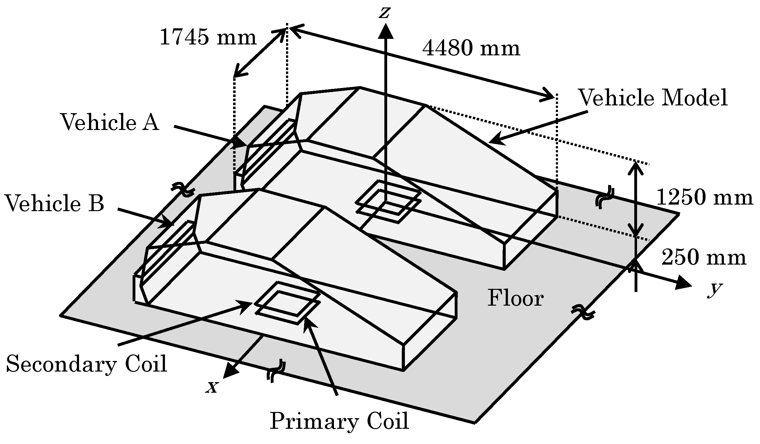
Figure 1. Analysis model of vehicles A and B.
Wevj 10 00041 g001
Figure 2. Two parking patterns of two vehicles A and B: (a) Parking pattern 1; (b) Parking pattern 2.
Wevj 10 00041 g002
Figure 3. Positional relation between the human model and vehicles A and B.
Wevj 10 00041 g003
Figure 4. Distribution of leakage magnetic field in x-y place at z = 120 mm for (a) only vehicle A being charged and (b) both vehicles being charged.
Wevj 10 00041 g004
Figure 5. Average magnetic field strength.
Wevj 10 00041 g005
Figure 6. Induced electric field 99.9th percentile value of Ein for the human model for each parking configuration.
Wevj 10 00041 g006
Figure 7. Values of |Hx|, |Hy|, and |Hz |in the analysis area for parking configurations (a) 1 and (b) 2.
Wevj 10 00041 g007