1. Introduction
Nanotubes (NTs) are a family of compounds having properties as conducting or semiconducting materials with good heat conductivity and a large surface area. They have potential use, for instance, in the field of materials science, nanotechnology [
1], molecular electronics [
2,
3], and medicine [
4].
The properties of nanotube depend upon several factors including chemical constitution [
5], configuration [
6,
7], diameter [
8], and length [
9].
Carbon NTs (CNT) when are doped with nitrogen increase their conductivity. Theoretical systematic studies [
5] have been carried out to analyze this effect on the properties, of some particular zigzag and armchair CNT structure modifications, or defects, such as a number of vacancies, and replacement of carbon atoms by one to four nitrogen atoms.
Methods of NT structure generation by computers are known. For instance Maruyama et al. [
10] generate Cartesian coordinates of regular nanotubes starting with a program that requires a specified (n, m) chirality, while Melchor and Dobado [
11] determine coordinates of a heterojunction between two arbitrary carbon nanotubes; both group of researchers start from a graphene sheet. Their aim is to create, by software, nanotubes with hexagonal cyclic carbon structures, generating some specific “defects”. Particularly, Melchor and Dobado introduce only one pentagon and one heptagon for their heterojunctions. Their software CoNTub [
11] is a nanotube generation algorithm that connects both tubes based on a topological algebra that takes into account a number of combinations and relative orientations between the considered defects by means of a continuous strip of hexagons containing pentagon and heptagon cycles as defects. However, this software does not generate zipper nanotubes neither it takes into consideration the exchange of carbon atoms by other atoms in order to form doped nanotubes.
The most important “defects” or variation requirements in the nanotube structures however belong to another sequence of cycles that give rise for instance to zipper nanotubes which include cycles of 5, 7 and 8 members [
3,
12].
Curtiss et al. [
3] using computer simulation tools, have inserted molecular moieties of two carbons into a single-walled carbon nanotube; however this design is not just a generation software for carbon nanotubes, in the sense that they apply modifications to an already created NT structure. They find that a good method of design is by inserting, horizontally, a two carbon moiety at the mid-point of two opposite sides of a hexagon thus creating two condensed pentagons surrounded by heptagons. If insertion is done in different positions located at a same distance from the end of the NT a bumping nanotube is formed, but when insertion is done along the longitudinal axis of the NT a zipper NT is obtained. If insertion is repeated along the longitudinal axis from one end to the other, is also possible to get multiple zipper nanotubes.
This means that in order to get a wide molecular structure diversity of nanotubes a general algorithm for NT generation with a common and simple software package is necessary.
In this paper a general nanostructure generation method based on a flat graphene sheet constituted by hexagons of carbon atoms is described. On this generated graphene sheet several modifications are done to finally obtain a nanotube which can have variable composition, configuration, shape, and size, including cycles of different sizes as in zipper NTs. Our algorithm generates zipper NTs and allows for changing NT carbon atoms for other atoms.
2. Results and Discussion
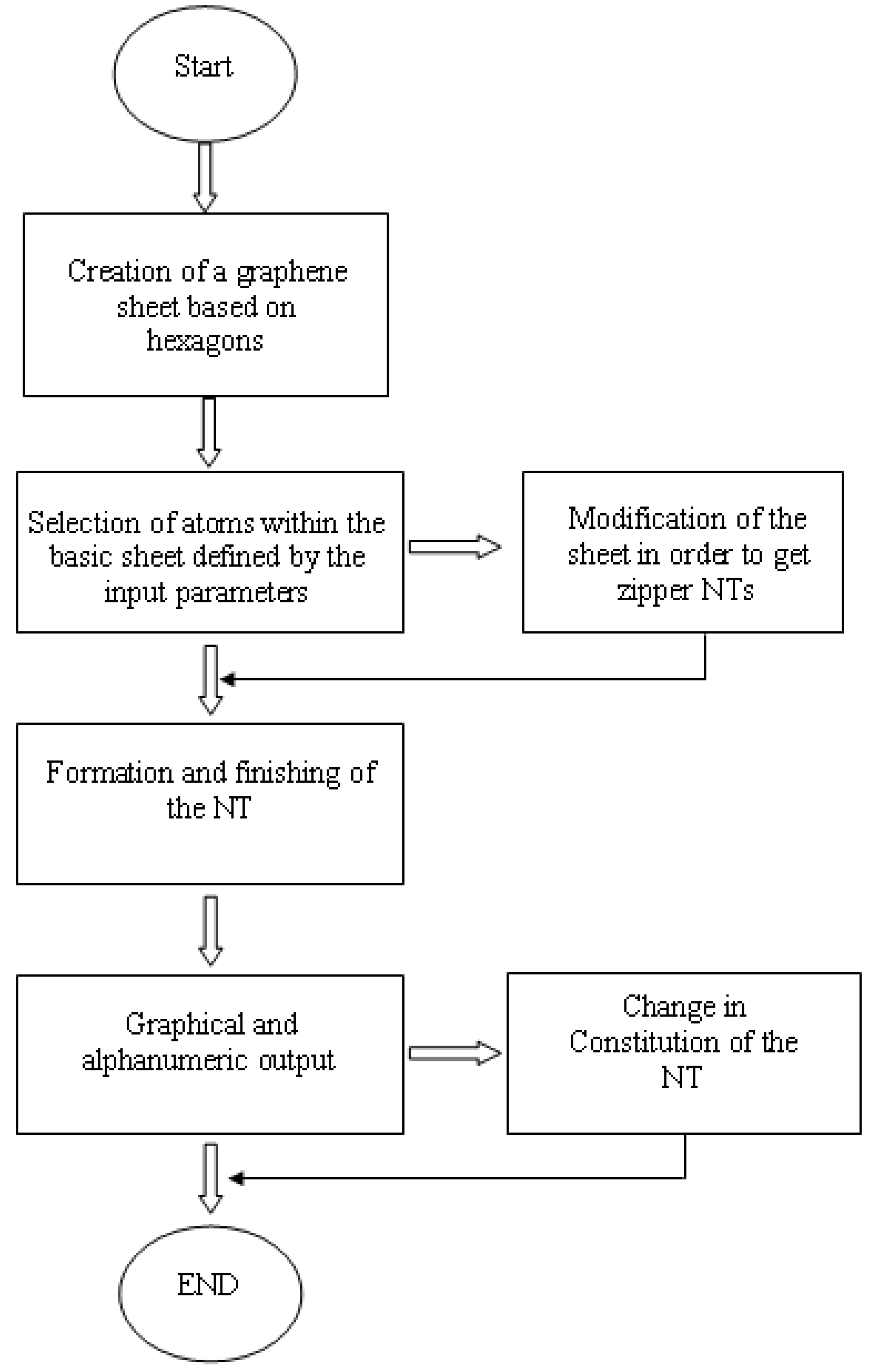
The developed general method called here molecular computer assisted design (MCAD) is shown in
Figure 1 where the main generation steps to get nanotubes with different constitution, configuration, size, and shape are presented. A description of each module follows, which are represented on the GUI developed for visualization and modification of generated nanotubes.
2.1. Creation of the graphene sheet
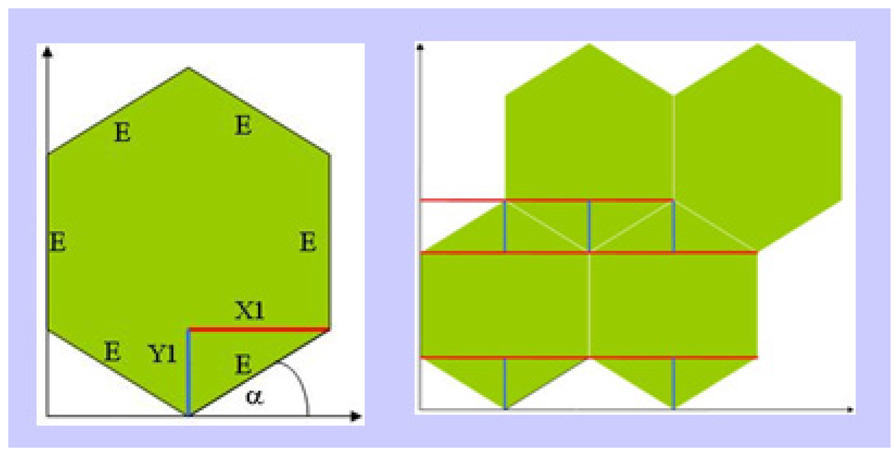
Simple geometrical relationships associated with a six-member cycle were taken into account for establishing the basic graphene sheet by first determining distances X1 and Y1 shown in
Figure 2. The basic geometrical elements of each cycle are repeated in order to generate a graphene sheet having atom coordinates available for further processing. In
Figure 2, E = bond length of 1.47 Å; α = 30°; X1 = E cos α; Y1 = E sin α.
The graphene sheet is generated from these values. Each of the atoms is represented as an element of a bidimensional array which results in connectivity information.
Figure 1.
General flow diagram of the MCAD system for generation of nanotubes, starting from a graphene sheet.
Figure 1.
General flow diagram of the MCAD system for generation of nanotubes, starting from a graphene sheet.
2.2. Selection of atoms comprising the nanotubes
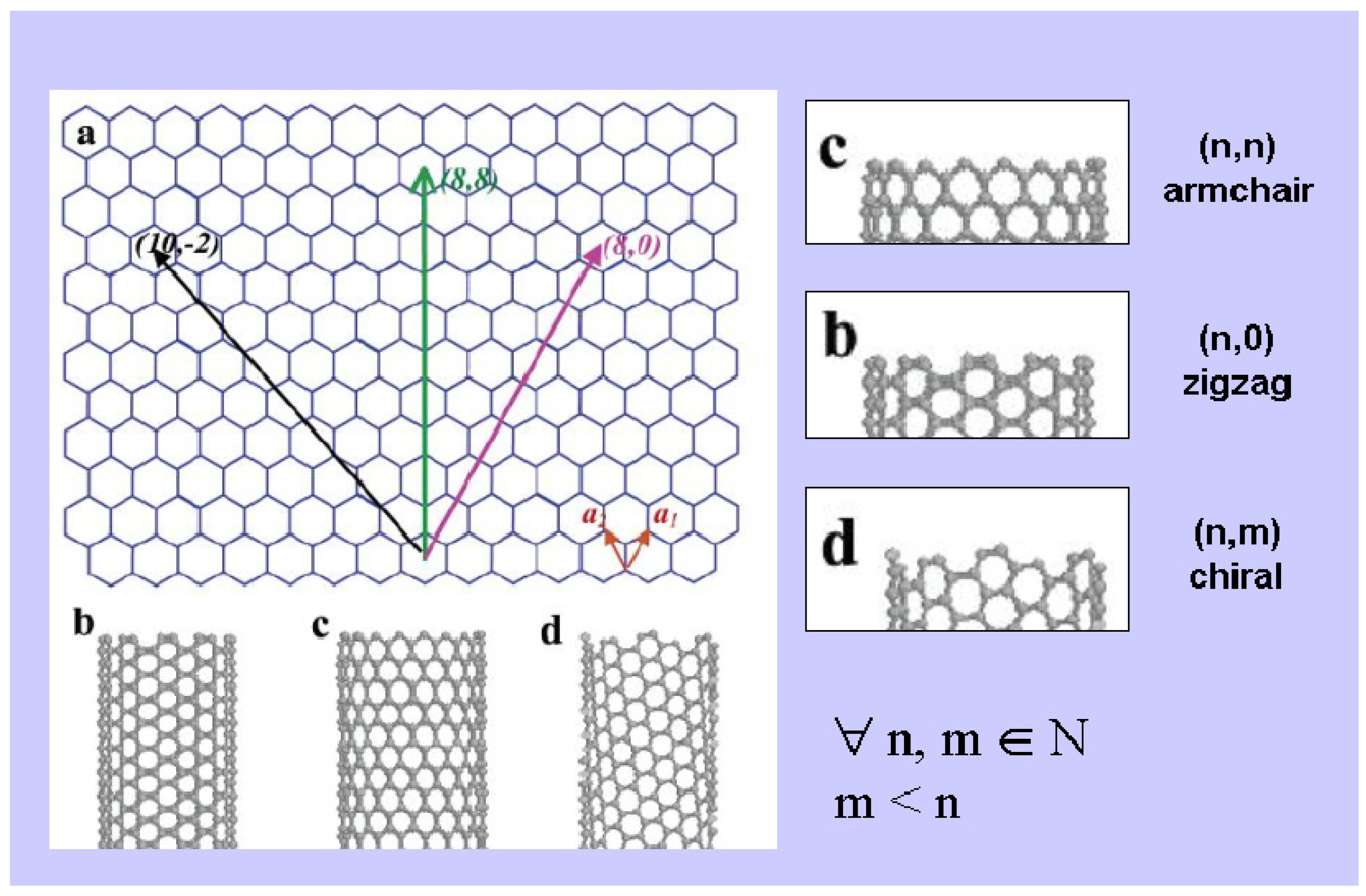
In this step the NT configuration and size is defined. The user interactively indicates the kind of NT going to be built by specifying the input key parameters n, m [
13], as illustrated in
Figure 4 and
Figure 5, as well as the length of the NT.
Figure 2.
Schematic representation of basic geometrical elements used.
Figure 2.
Schematic representation of basic geometrical elements used.
Figure 3.
Representation of different NT configurations and associated vectors.
Figure 3.
Representation of different NT configurations and associated vectors.
Figure 4.
Schematic representation of parameters defining NT diameter and configuration.
Figure 4.
Schematic representation of parameters defining NT diameter and configuration.
Unitary vectors a1 and a2 (denoted as red arrows) function as the basic unit of movement in network coordinates (a1 > 0 and a1 ≥ |a2|). Accordingly, final vector (2,2) defines an armchair NT (for comparison, a vector (2,2) in Cartesian coordinates is also shown); final vector (3,0) defines a zigzag NT, and final vector (3,1) defines a chiral NT.
Once the graphene sheet is generated according to parameters n and m, the length of the nanotube is selected by tracing a rectangular area starting from the defined vector representing one of the shorter rectangular sides. This operation defines the size of the sheet that has to be finally generated to be rolled up.
2.3. Formation and Finishing of the Nanotube
The way in which rolling up takes place, is represented graphically in
Figure 5, wherein coordinates defined in the plane become coordinates of a cylinder (the NT). Coordinates of point B in the flat sheet are transformed to coordinates on the cylinder by means of the arc length equation. The NT notation used in this work is formed by the number of atoms along C side on
Figure 5, and also the number of parallel layers (in relation to C side) which defines the NT length, numbered along A or D sides. In
Figure 5 red lines define a graphene sheet giving a zigzag (C8)6 NT according to the explained notation.
Figure 5.
Schematic view representing the rolling up process.
Figure 5.
Schematic view representing the rolling up process.
To accomplish the rolling up process the algorithm makes use of the following main classes:
Rectangular_Area: This is a class that contains mainly 8 variables, 4 of them are points and the other 4 are straight lines. This class was created with the purpose of generating the information needed for cutting the selection area on the graphene sheet and then rolling up the selected area. Some methods included in this class are:
- ➢
Rectangular_Area: Creates the rectangular area, on the base of two points for the height, and two points for the width, or on the base of four points of a rectangle.
- ➢
Contains: This method returns true value if the point in consideration belongs to the selected area, or false if it does not.
- ➢
Distances: Over each point (or atom) of the graphene sheet, it creates a perpendicular pair of straight lines (a cross) which are, in turn, perpendicular to the rectangle sides, and returns the distance of both traced lines to the respective sides; one of these values corresponds to the height of the atom in the cylinder, and the other distance corresponds to the rotation of the point during the rolling up.
- ➢
ToCircle: It changes Cartesian coordinates to circumference coordinates.
Straight: This class simulates a straight line having the same value as a geometrical straight line, between the starting and the finishing points. Two of the most important methods are, “create a parallel straight line” and “create a perpendicular straight line”.
So, the width of the selected area represents the perimeter of the cylinder, and the length of the selected area is the height of the cylinder.
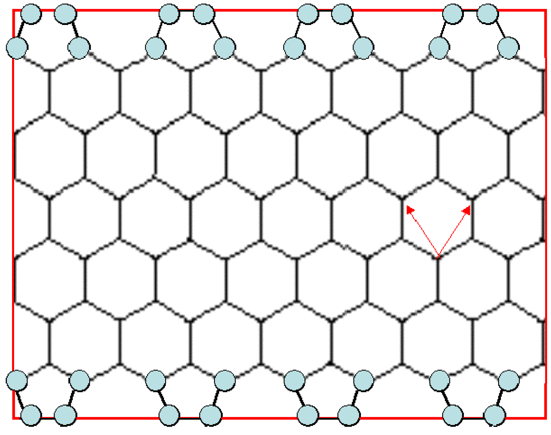
Generation of a zipper, is represented in
Figure 6, where a graphene sheet corresponding to a (3,3) armchair NT is modified by adding atoms such that pentagons are formed at both edges of the sheet previous to rolling it up.
In
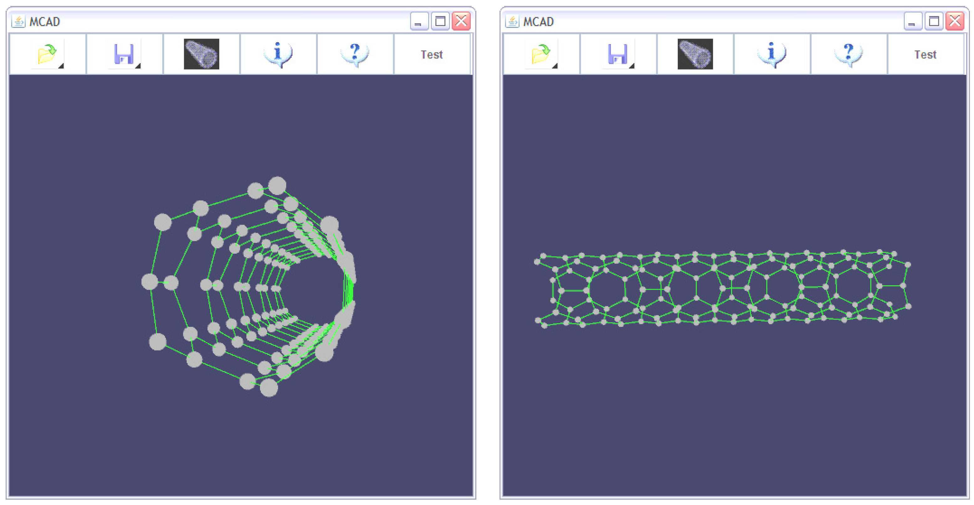
Figure 7 is represented a (C13)10 zipper NT; this notation is used to represent 13 carbon atoms in a layer giving the NT width and 10 layers length, generated with MCAD and optimized at the level of MM+ forcefield using HyperChem software package [
14]. A pattern of two condensed pentagons alternating with octagons is repeated along NT longitudinal axis.
Figure 6.
Modification of the graphene sheet to generate a zipper NT.
Figure 6.
Modification of the graphene sheet to generate a zipper NT.
Figure 7.
A zipper NT representation generated by MCAD.
Figure 7.
A zipper NT representation generated by MCAD.
When two modified graphene sheets are matched together, and then rolled up as shown for zipper NT generation, a multiple zipper NT is obtained.
In
Figure 8 processes used to get the correct NT structures (including zipper NTs) after the graphene sheet rolling up step is carried out, are shown. In process 1, coordinates of atoms that are very near or that overlap to each other, are fused into single coordinates. In process 2, non-bonded atoms that are located at a distance similar to a bond length become linked. In process 3 non-bonded atoms located at a distance highly different from a bond length, are deleted.
Figure 8.
Finishing processes used for creating a nanotube.
Figure 8.
Finishing processes used for creating a nanotube.
2.4. Alphanumeric and Graphical Output
Standard alphanumeric output for a NT having three layers of six carbon atoms each (written as (C6)3) generated by MCAD, compatible with other software packages for property calculations (i.e. HyperChem), is given below (for simplicity, hydrogen atoms are not shown).
forcefield mm+
mol 1
atom 80 - C ** - 0 0.60370505 -1.0456481 5.11 2 72 s 87 s
atom 121 - C ** - 0 0.60370517 1.045648 0.73 3 114 s 115 s 85 s
atom 99 - C ** - 0 -0.60370517 -1.045648 0.0 2 92 s 107 s
atom 109 - C ** - 0 0.6037053 1.045648 5.11 2 101 s 72 s
atom 108 - C ** - 0 -0.6037051 1.045648 2.92 3 100 s 101 s 115 s
atom 107 - C ** - 0 -1.2074103 1.7564588E-15 0.73 3 99 s 100 s 114 s
atom 94 - C ** - 0 -1.2074103 1.2763726E-7 5.11 2 87 s 101 s
atom 93 - C ** - 0 -0.6037052 -1.045648 2.92 3 86 s 87 s 100 s
atom 92 - C ** - 0 0.60370517 -1.045648 0.73 3 85 s 86 s 99 s
atom 101 - C ** - 0 -0.60370505 1.0456481 4.38 3 94 s 108 s 109 s
atom 100 - C ** - 0 -1.2074103 6.381863E-8 2.19 3 93 s 107 s 108 s
atom 79 - C ** - 0 1.2074103 -6.381863E-8 2.92 3 72 s 86 s 115 s
atom 72 - C ** - 0 1.2074103 -1.2763726E-7 4.38 3 79 s 80 s 109 s
atom 115 - C ** - 0 0.6037052 1.045648 2.19 3 108 s 121 s 79 s
atom 114 - C ** - 0 -0.60370517 1.045648 0.0 2 107 s 121 s
atom 87 - C ** - 0 -0.6037053 -1.045648 4.38 3 80 s 93 s 94 s
atom 86 - C ** - 0 0.6037051 -1.045648 2.19 3 79 s 92 s 93 s
atom 85 - C ** - 0 1.2074103 -2.9573022E-16 0.0 2 92 s 121 s
endmol 1
This output example is written as a “.hin” format which will be open with HyperChem program; it can be saved as a “.ent” format as a protein data bank (PDB) compatible file.
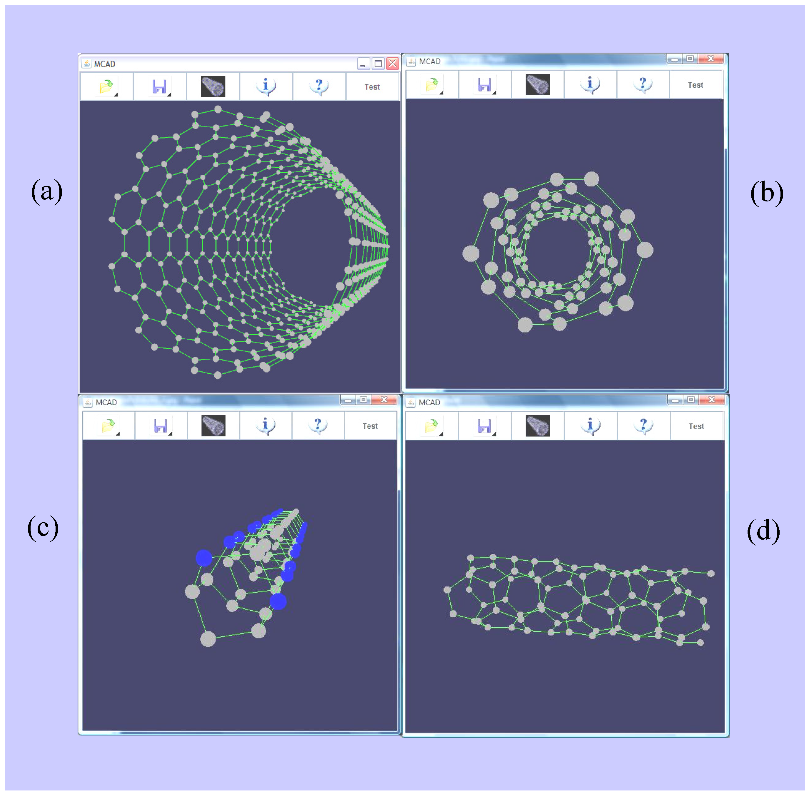
Other graphical outputs of MCAD are represented in
Figure 9, which shows different NT configurations: (a) (10,10) armchair NT (perspective view); (b) (4,2) chiral NT (front view); (c) (6,0) zigzag (C4N2)10 NT modified with nitrogen atoms (in blue) (perspective view); (d) (4,2) chiral NT (side view; same as in (b))
Figure 9.
Examples of different NT configurations generated by MCAD such as (a) armchair, (b, d) chiral, and (c) zigzag nanotubes doped with nitrogen.
Figure 9.
Examples of different NT configurations generated by MCAD such as (a) armchair, (b, d) chiral, and (c) zigzag nanotubes doped with nitrogen.
2.5. Modification of NT Constitution
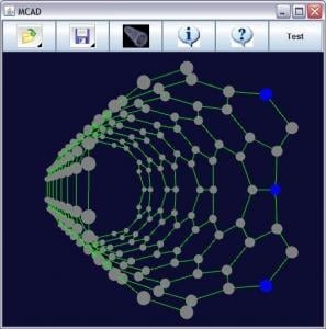
Once the NT is created it is displayed on the screen and one or more chosen carbon atoms could be changed, for instance by nitrogen atoms, with the aid of the Graphical User Interface built for this aim. NTs created in this way can be exported into a standard format.
Table 1 shows the MCAD performance for generating NTs and its comparison with the well known HyperChem software. As can be seen MCAD is able to generate, in a very short time, the NT for different numbers of atoms, whereas with HyperChem some difficulties in achieving such results are encountered. Generation of (C4N2)10 nanotube with MCAD involves manual replacement of 20 carbon atoms by nitrogen atoms, this fact explaining the observed performance.
Table 1.
Nanotube generation MCAD performance, and its comparison with HyperChem.
Table 1.
Nanotube generation MCAD performance, and its comparison with HyperChem.
| N° | Nanotube | MCAD
(sec) | HyperChem (sec) |
| 1 | (C6)3 | 7 | 240 |
| 2 | (C6)5 | 7 | 320 |
| 3 | (C6)10 | 8 | 450 |
| 4 | (C4N2)10 | 160 | 550 |
| 5 | (C12)10 | 9 | 1320 |
| 6 | (C6)20 | 9 | 700 |
| 7 | chiral, C12, 15 Å length | 10 | NA* |
| 8 | armchair, C12, 15 Å length | 10 | NA |
| 9 | zigzag, C12, 15 Å length | 10 | NA |
With the commercial software it is possible to generate nanostructures manually atom by atom, or groups of atoms, which become more complex as the number of atoms of the NTs increases, mainly due to additional amount of atoms in a layer.
Since MCAD is specifically designed for NT generation, it generates NTs in just some seconds according to the input parameters provided for the automatic generation procedure. Parameters used by the algorithm determine diameter, length, and configuration, and are provided by the user at the beginning of the generation process which allows for inmediate nanostructure visualization.
Additionally, the generation system allows for compatibility with other software packages, and after NTs have been generated, they can be exported, for instance, to HyperChem where any other structure modifications can be carried out. MCAD generates NTs with no hydrogen. Structures can be exported to others software packages for adding these atoms if necessary.
Features like automatic fast generation of NTs, and compatibility with other software packages, allows for obtaining many different structures that can be graphically represented which can be modified at will. MCAD also allows for obtaining NTs with variable dimensions into a standard format capable of being submitted to other software packages for carrying out calculations of specific properties.
Figure 10 represents the output for (C12)10 nanotube of
Table 1 wherein upper structures represent manual HyperChem output (side and perspective views), and lower structures represent output of the automatic MCAD (side and front views).
2.6. System Requirements
The software was implemented on a Laptop DELL XPS M1210, Centrino Duo Processor, 1 GB RAM Memory and 80 GB Hard drive, using Eclipse Europa version 3.3.0 as Java Project Editor or Manager, with the Java version 1.6 Compiler and Java 3D 1.5.1 plugin.
The alphanumerical output was checked using HyperChem version 7.0 and 7.5.
The application was tested into an Intel Pentium 4 Workstation using Microsoft Windows XP, Java J2SE JRE 1.6.0_07 and Java 3D.
Any computer that support Windows XP, Java and Java 3D could run this application.
This algorithm can be installed in your own computer. For such a task you can access it through the supplementary material together with instructions for installation.
Figure 10.
Outputs of (C12)10 nanotube of
Table 1.
Figure 10.
Outputs of (C12)10 nanotube of
Table 1.
3. Conclusions
The algorithm developed in this paper allows for the generation of different NT configurations according to some predetermined parameters; it has been developed based on a graphene sheet of carbon created ad hoc, and then rolling it up to form one of an armchair, zipper, multiple zipper, zigzag, or chiral NT. Each step of the process has been described in detail using simple algebra relationships, and NTs are displayed on the graphical user interface (GUI) created for these purposes. Generation of the graphene sheet was done in an efficient way by calculating the appropriate size according to given initial parameters. Modification of the sheet in order to form zipper NTs allows for the generation of different NTs containing pentagons and octagons along the axis of the NT. A finishing treatment necessary to properly carry out NT generation by joining the sides of the graphene sheet is based on three sequential steps, fusion, linking, and deletion of some particular atoms, being quite effective to provide the correct nanostructures in terms of bonding and valence allocation. Most interesting, the output of MCAD has a standard format compatible with known and widely used molecular properties calculation software.
In this way a useful tool has been created which could be of help for designing and then calculating, with other software, molecular properties for different kind of NTs, for instance nitrogen doped NTs which could have interesting technological applications based on their conducting properties.
