1. Introduction
Permanent magnet synchronous (PMS) machines (PMSMs) are widely recognized for their simple structure, high efficiency, and high energy density. Due to these advantages, they are extensively used in applications such as robotics, electric vehicles, computer numerical control (CNC) machines, pumps, and various industrial systems [
1]. Despite these merits, PMSMs exhibit strong nonlinear coupling and are affected by disturbances and uncertainties, including parameter variations, load disturbances, friction effects, and unmodeled dynamics [
2].
In renewable energy systems (ESs), PMSM-based machines are commonly employed for electrical energy (EE) generation from wind energy (WE) sources [
3]. In such configurations, two power electronic inverters are typically required to interface the generator with the grid [
4]. Consequently, ensuring high-quality energy transfer requires advanced control strategies capable of regulating both machine-side and grid-side converters (MSC and GSC). The performance of these inverters plays a crucial role in overall system behavior, as inadequate control can significantly degrade power quality (PQ), particularly under parameter variations and external disturbances.
Among conventional control strategies, the proportional–integral (PI) controller is widely used in PMSM-based systems due to its simplicity and ease of implementation [
5]. However, its performance is highly dependent on accurate system parameter tuning, making it sensitive to model uncertainties [
6]. Moreover, PI-based control exhibits limited robustness against external disturbances and parameter mismatches, which can negatively affect system performance [
7]. These limitations are often reflected in degraded PQ and increased current total harmonic distortion (THD). Therefore, improving control performance and robustness beyond conventional PI-based methods has become a key research focus.
From a broader perspective, the main control strategies used in PMSM and permanent magnet synchronous generator (PMSG)-based renewable ESs can be systematically classified into four categories: classical linear control, nonlinear robust control, intelligent control, and hybrid fractional-order intelligent control.
Classical linear control methods, mainly represented by PI control, are widely adopted in industrial applications due to their simple structure, low computational burden, and ease of implementation. However, their effectiveness is strongly dependent on accurate system modeling and parameter tuning, and they perform poorly under nonlinear operating conditions and disturbances.
To overcome these limitations, nonlinear robust control techniques such as sliding mode control (SMC) and backstepping control (BC) have been developed. SMC is well known for its strong robustness against disturbances and fast dynamic response. However, it suffers from the chattering phenomenon and requires an accurate mathematical model, which limits its practical applicability. Similarly, BC provides a systematic nonlinear control design framework and improves stability performance, but it is highly dependent on system modeling accuracy and may exhibit degraded performance under parameter uncertainties, leading to increased steady-state error (SSE) and undershoot. Recent research has demonstrated the wide applicability and effectiveness of the BC method in addressing nonlinear dynamics, uncertainties, and external disturbances across diverse engineering systems. In the field of renewable energy conversion, study [
8] proposed a BC method for a multilevel modified space vector modulation (SVM) inverter integrated into a variable-speed induction generator-based dual-rotor WE system. The obtained results revealed significant improvements in active and reactive power (
Ps and
Qs) regulation, reduced harmonic distortion, enhanced tracking performance, and increased overall system efficiency. The study confirmed that the BC method effectively handles the nonlinear characteristics of WE conversion systems. Nevertheless, the controller required accurate system modeling and involved a relatively complex design process, which may complicate practical implementation in large-scale wind farms.
The effectiveness of the BC method was also demonstrated in aerial vehicles. Study [
9] developed a fault-tolerant adaptive BC approach for quadrotors experiencing actuator faults. Experimental validation showed that the proposed controller maintained stable flight and accurate trajectory tracking even under partial actuator failures. The adaptive mechanism improved fault accommodation capabilities and enhanced robustness against uncertainties. However, the controller design required careful parameter tuning and increased computational complexity, particularly when multiple faults occurred simultaneously. Despite these challenges, the study highlighted the suitability of the BC approach for safety-critical unmanned aerial vehicle (UAV) applications.
Similarly, study [
10] introduced an optimal disturbance-observer-based fuzzy proportional-integral-derivative (PID) backstepping controller for autonomous vehicles equipped with steer-by-wire systems. The proposed approach combined the advantages of fuzzy logic (FL), disturbance observers, PID control, and BC approach design to improve vehicle stability and trajectory tracking. Simulation results demonstrated reduced tracking errors, improved disturbance rejection, and enhanced robustness under varying driving conditions. However, integrating multiple intelligent control techniques increased implementation complexity and computational requirements. Furthermore, the effectiveness of the controller depended heavily on accurate disturbance estimation and proper tuning of FL parameters.
In another contribution addressing complex nonlinear systems, study [
11] proposed a robust BC approach for a twin rotor MIMO (Multiple-Input, Multiple-Output) system using a Radial Basis Function (RBF) neural network tuned high-gain observer. The obtained results showed superior trajectory tracking accuracy, faster convergence, and effective disturbance compensation compared with conventional methods. The integration of the RBF neural network improved state estimation and enhanced robustness against modeling uncertainties. Nevertheless, the proposed approach suffered from increased computational burden and required extensive training and parameter adjustment of the neural network, which may limit real-time implementation in highly constrained environments.
Advancements in theoretical control design were presented in the study [
12], which developed a fractional-order BC strategy based on the Mittag–Leffler stability criterion for uncertain chaotic systems. The proposed controller successfully stabilized non-commensurate fractional-order chaotic systems under external disturbances and parameter uncertainties. Results demonstrated faster convergence rates, improved robustness, and enhanced stability characteristics compared with traditional control techniques. Despite these advantages, the complexity of fractional-order calculus and the challenges associated with selecting appropriate fractional parameters remain significant limitations. Moreover, practical implementation may require substantial computational resources and advanced numerical algorithms.
The applicability of the BC approach to smart structures was investigated in study [
13], which combined finite element dynamic modeling with an adaptive BC approach. The proposed methodology effectively suppressed vibrations and improved structural stability in smart flexible systems. The adaptive controller successfully compensated for parameter variations and external disturbances while maintaining accurate performance. The study confirmed that the BC approach can provide reliable vibration attenuation in complex structural systems. However, the effectiveness of the approach depends on the accuracy of the finite element model, and the computational effort increases significantly for large-scale structures with high degrees of freedom.
In the UAV domain, study [
14] addressed quadrotor trajectory tracking under wind disturbances using the BC approach combined with various optimization techniques. The results indicated substantial improvements in tracking accuracy, disturbance rejection capability, and overall flight stability. Optimization algorithms enhanced controller parameter selection and improved system performance under adverse environmental conditions. Nevertheless, wind uncertainty remains a major challenge, and optimization procedures may become computationally intensive when dealing with real-time applications or rapidly changing operating conditions.
A related study [
15] proposed a robust backstepping SMC strategy for a morphing quadcopter UAV. By combining the BC approach with sliding mode techniques, the authors achieved strong robustness against parameter variations and external disturbances while ensuring stable flight performance during wing configuration changes. The results demonstrated improved trajectory tracking and resilience under uncertain conditions. However, the controller inherited some limitations associated with the SMC method, including potential chattering effects and increased control complexity. Furthermore, the morphing mechanism introduced additional dynamic uncertainties that required careful modeling and compensation.
In marine propulsion systems, study [
16] developed a nonlinear state observer-based adaptive finite-time command-filtered backstepping speed controller for a PMSM propulsion system used in hybrid ships. The proposed controller achieved fast speed convergence, high tracking precision, and excellent disturbance rejection. The finite-time control framework improved transient response and reduced settling time compared with conventional approaches. Nevertheless, the integration of multiple advanced techniques, including nonlinear observers and command filters, increased controller complexity and computational demand. Accurate parameter identification also remained essential for achieving optimal performance.
For autonomous underwater vehicles (AUVs), study [
17] proposed an event-triggered adaptive BC approach capable of handling input saturation. The proposed strategy significantly reduced communication and computational resources while preserving tracking performance and system stability. Results demonstrated effective trajectory tracking, robustness against uncertainties, and efficient utilization of onboard resources. However, the design of event-triggering mechanisms introduces additional challenges related to stability analysis and threshold selection. Moreover, underwater environments are characterized by highly uncertain hydrodynamic effects that may affect controller performance under practical operating conditions.
Finally, study [
18] presented a robust backstepping-sliding control approach for quadrotor UAVs incorporating disturbance compensation mechanisms. The proposed controller successfully improved tracking accuracy, enhanced robustness against external disturbances, and maintained flight stability during aggressive maneuvers. Disturbance compensation significantly reduced the impact of environmental uncertainties and modeling errors. However, similar to other hybrid backstepping-sliding mode approaches, the controller exhibited increased design complexity and potential chattering issues. Additionally, real-time implementation may require high-performance computational hardware to guarantee a satisfactory response.
Overall, studies [
8,
9,
10,
11,
12,
13,
14,
15,
16,
17,
18] collectively demonstrate that the BC approach remains one of the most effective nonlinear control methodologies for modern engineering systems. Its principal strengths include systematic Lyapunov-based stability design, strong tracking performance, robustness against uncertainties, and adaptability to highly nonlinear dynamics. Furthermore, the integration of the BC approach with adaptive control, neural networks, FL method, SMC method, disturbance observers, optimization algorithms, and finite-time techniques has significantly expanded its capabilities. Nevertheless, common challenges persist across most applications, including controller complexity, dependence on accurate mathematical models, computational burden, parameter tuning difficulties, and practical implementation constraints. Despite these limitations, the reported results consistently indicate that BC approach-based controllers achieve superior stability, faster convergence, improved disturbance rejection, and enhanced robustness, making them highly attractive for renewable ES, autonomous vehicles, UAVs, marine propulsion systems, smart structures, and other advanced nonlinear control applications.
In parallel, intelligent control approaches such as FL control have gained significant attention in renewable ESs due to their model-free nature. FL controllers do not require precise mathematical models and are effective in handling nonlinearities and uncertainties. They have demonstrated improved performance in reducing oscillations, THD, and transient errors compared to PI-based control. However, their design relies heavily on expert knowledge, and the increasing number of FL rules can significantly increase system complexity, while lacking a systematic mathematical formulation for optimization.
To further enhance performance, hybrid and fractional-order intelligent control strategies have been introduced. These methods combine the advantages of nonlinear control, the FL method, and fractional calculus to improve flexibility and dynamic performance. In particular, fuzzy fractional-order approaches introduce additional tuning degrees of freedom, enabling improved robustness, better transient response, and enhanced PQ. Nevertheless, these approaches also introduce higher computational complexity and require careful parameter tuning to ensure stable operation.
In summary, classical PI control is simple but limited in performance, nonlinear methods such as SMC and BC improve robustness but remain model-dependent, FL control enhances adaptability but increases design complexity, while hybrid fractional-order approaches provide superior performance at the cost of increased computational and design complexity. This comparison clearly indicates that no single conventional method fully satisfies the stringent requirements of modern multi-machine WE (MMWE) systems. Work [
19] provides a comprehensive evaluation of generator technologies and power converter configurations used in multi-megawatt WE conversion systems. The study highlights that permanent magnet synchronous generators, coupled with full-scale power converters, have emerged as a promising solution for large offshore wind turbines (WTs) due to their high efficiency and superior reliability, as well as the elimination of gearbox maintenance issues. This work highlights the increasing use of modular multi-level power converters and advanced power electronics interfaces, which improves grid integration and PQ in high-capacity wind farms. Key advantages identified include enhanced energy extraction, reduced maintenance requirements, and improved operational flexibility under varying wind conditions. However, the review also points to several limitations, including the high cost and supply chain dependency of rare-earth element permanent magnets used in PMSGs, the increasing complexity of power electronics converters, and challenges related to thermal management, failure tolerance, and converter reliability in harsh marine environments. Overall, the study concludes that despite the existing technical and economic challenges, advanced generator and converter technologies play a crucial role in improving the performance, efficiency, and scalability of next-generation multi-megawatt WE systems. The authors of work [
20] see the integration of photovoltaic solar, wind, and hybrid renewable ESs into multi-machine ESs as a promising solution, with a particular focus on improving ES oscillation control units. The study highlights that the increasing use of renewable energy sources significantly impacts ES stability due to their intermittent and variable nature. The researchers found that advanced optimization techniques, including heuristic algorithms such as particle swarm optimization (PSO), genetic algorithms (GA), and artificial intelligence (AI)-based methods, can effectively improve the performance of ES stabilizers and damping controllers. Among the key advantages identified is improved damping of low-frequency oscillations, leading to enhanced dynamic stability and reliability of interconnected power grids. Furthermore, hybrid solar and WE systems offer greater operational flexibility and more balanced energy production compared to standalone renewable energy sources. However, the report also reveals several challenges, including the complexity of controller design, the computational burden of optimization algorithms, and the uncertainties arising from the variability of renewable energy production. The researchers conclude that while significant progress has been made in improving oscillation controllers, further research is needed to develop robust, adaptive, and real-time control strategies capable of maintaining system stability under high levels of renewable energy penetration. In work [
21], the authors proposed a BC strategy to improve the stability of ESs under diverse operating conditions. The study demonstrated that the proposed controller effectively enhances transient stability, reduces oscillations, and provides robust performance against disturbances and parameter changes. A key advantage of this approach is its systematic design for nonlinear control, ensuring better dynamic response and stability compared to conventional control methods. However, this strategy has some limitations. The process of designing a BC strategy effect is mathematically complex and relies heavily on an accurate system model. Furthermore, its application in large-scale power systems may increase computational demands and present practical deployment challenges. Overall, the proposed method offers a promising solution for improving stability, although further validation under realistic operating conditions is necessary. In work [
22], the researchers proposed an improved control strategy using voltage reduction technology for double-star induction WT systems. The study showed that the improved controller achieves superior motion tracking performance, faster dynamic response, and reduced power and torque ripple under varying wind conditions. Its main advantages include effective management of the nonlinear behavior of the WT system and improved power generation quality. However, the proposed approach also has some drawbacks. The controller design is relatively complex and requires precise system parameters to achieve optimal performance. Furthermore, the computational load may be higher compared to traditional control methods, potentially impacting real-time implementation in large-scale applications. Overall, this work presents a promising control solution for enhancing the efficiency and stability of double-star induction generator-based WE systems. In [
23], the authors presented an improved sensorless step-down control strategy for brushless doubly fed reluctance generator (BDFRG) using a high-gain adaptive controller. The proposed approach improves rotor speed and system state estimation without the need for mechanical sensors, thereby reducing system costs, maintenance requirements, and reliability issues associated with sensor failures. The results demonstrated improved tracking accuracy, faster dynamic response, and enhanced robustness against parameter changes and external disturbances. However, the method has some limitations. The adaptive monitor and rollback controller increase the overall control complexity and computational requirements. Furthermore, the monitor’s performance may be sensitive to modeling inaccuracies and measurement noise, particularly under harsh operating conditions. Overall, this study presents an efficient and reliable sensorless control solution for WE systems based on dual-feed brushless AC generators, while emphasizing the need for further validation in practical applications. In work [
24], the authors proposed a modified multi-machine ES integrated with a dual-feed induction generator-based WE conversion system and an optimized damping controller to improve system stability. The results showed a significant improvement in low-frequency oscillation damping, faster stabilization times, and better dynamic performance under various disturbance scenarios. The study demonstrated the effectiveness of integrating renewable energy sources while maintaining ES stability. However, key challenges remain, including the variability of WE generation, the complexity of controller tuning, and the need for robust control strategies capable of handling uncertainties and varying operating conditions in large, interconnected ESs.
Motivated by these challenges, MMWE systems have emerged as an effective solution to meet increasing energy demand and improve power generation efficiency. By integrating multiple wind generators, MMWE systems enhance energy capture while reducing the size and cost of wind farms. In this study, a dual-PMSG configuration is considered, where each generator is driven by an independent WT.
In this context, FL-based backstepping control (FLBC) has been applied to both MSC and GSC to improve system performance. Although FLBC improves dynamic response and reduces oscillations compared to conventional BC method, residual ripples and performance limitations remain due to estimation-based dependencies.
To overcome these issues, this paper proposes a fuzzy fractional-order BC (FFOBC) strategy for MMWE systems. The proposed method integrates FL technique, fractional-order dynamics, and BC method to achieve enhanced robustness, reduced chattering, and improved PQ. The main contribution of this work lies in applying the FFOBC strategy to both MSC and GSC in a dual-PMSG system, ensuring improved stability and performance under varying wind conditions.
The second major contribution is the application of the proposed control strategy to a realistic MMWE system composed of two WTs, each connected to a PMSG. The system performance is validated through MATLAB 2021 simulations and compared with existing methods, including SMC method. Furthermore, different wind speed (WS) profiles are considered to evaluate robustness and effectiveness.
The main contributions of this work can be summarized as follows:
Enhancement of MMWE system performance and robustness.
Significant improvement in PQ and current waveform characteristics.
Reduction of current THD under varying operating conditions.
Mitigation of SSE and undershoot in PMSG output power.
Improvement of dynamic response and suppression of oscillations.
The remainder of this paper is organized as follows.
Section 2 presents the mathematical modeling of the WE system, including the WT, PMSG, rectifier, grid interface, and DC-link design.
Section 3 describes the proposed FFOBC strategy and its implementation.
Section 4 presents the simulation results and performance evaluation carried out using MATLAB under different operating conditions.
Section 5 provides a comprehensive discussion of the obtained results, highlighting the effectiveness, robustness, and power quality improvements achieved by the proposed control scheme.
Section 6 discusses the main challenges and limitations associated with the proposed approach and identifies potential directions for future improvements. Finally,
Section 7 concludes the paper and outlines future research perspectives.
2. Suggested Generation System
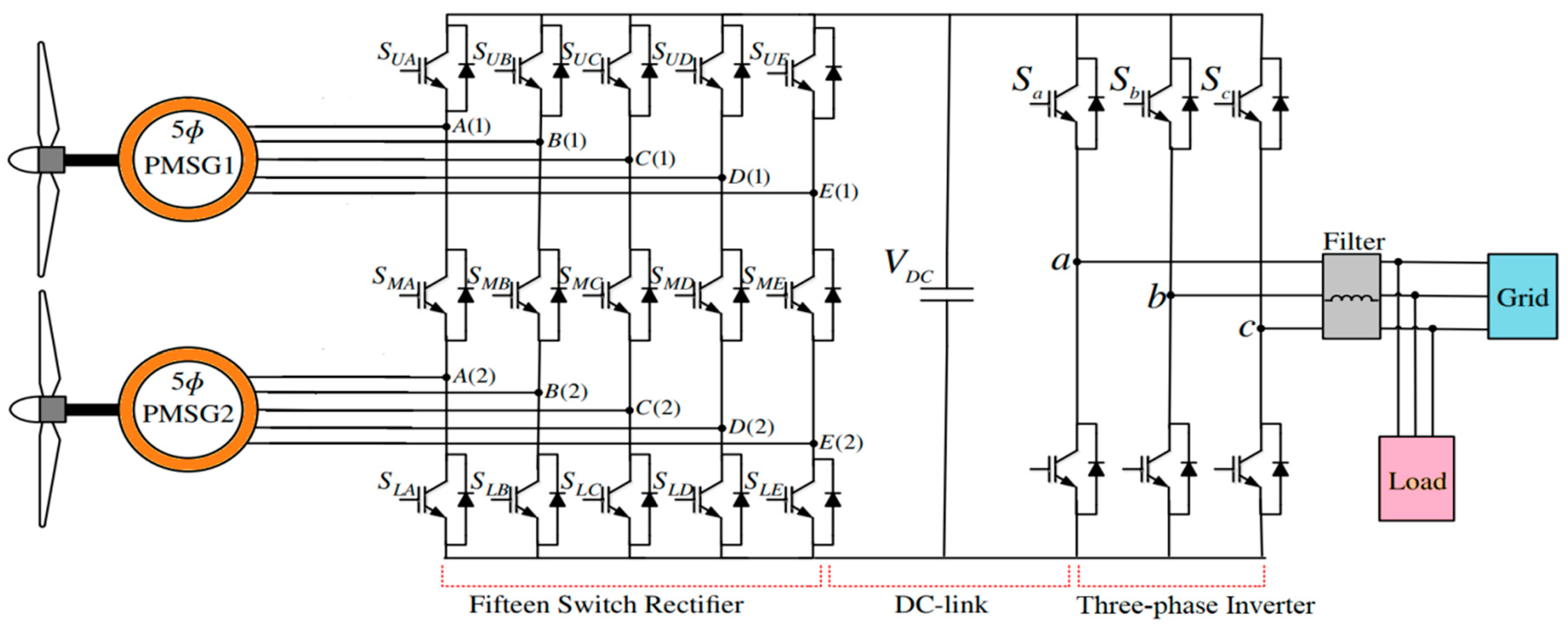
The proposed ES, illustrated in
Figure 1, represents a well-established and widely adopted WE conversion topology for medium- and high-power applications. The system is composed of several interconnected stages that operate sequentially to convert the kinetic energy available in the wind into EE suitable for grid integration. The main components include the WT, the PMSGs, power electronic converters, the DC-link, grid-side transformer, filtering elements, and the associated control units.
The WT captures the available WE and converts it into mechanical torque, which is subsequently transformed into electrical energy by the PMSGs. The generated electrical power is then processed through the power converters and DC-link stage to ensure proper voltage regulation, power flow control, and synchronization with the utility grid. The transformer provides voltage adaptation and electrical isolation, while the control system ensures maximum energy extraction, stable operation, and compliance with grid PQ requirements. The PMSG is particularly attractive due to its high efficiency, high power density, reduced maintenance requirements, and elimination of rotor excitation losses, making it highly suitable for modern WE applications [
25].
In addition to its energy conversion capability, the proposed ES contributes significantly to sustainability objectives by increasing the penetration of renewable energy sources into modern ESs. The integration of advanced control strategies enhances energy harvesting efficiency, minimizes conversion losses, improves PQ, and increases system reliability under varying wind conditions. Consequently, the system reduces dependence on fossil-fuel-based generation, lowers greenhouse gas emissions, and supports global decarbonization efforts. Furthermore, the efficient utilization of available wind resources enables long-term sustainable power generation while improving grid stability and energy security.
The primary challenge associated with implementing these systems lies in the meticulous selection of fundamental components and their quality. The selection of the generator has a substantial impact on the production costs and the system’s longevity, directly affecting the energy output. While the implementation of large turbines has the potential to enhance energy generation, this approach is complex and costly due to the necessity of employing substantial generators and power converters. Consequently, system expenses and energy output escalate. In an effort to reduce expenses and energy dissipation, two critical concerns in converter operations, this study incorporated an FSR. This rectifier, employed in multi-machine power conversion systems, integrates two rectifiers, thereby offering the primary benefit of reducing switch numbers while maintaining control system simplicity and circumventing superfluous complexities. Within the domain of control strategies, their significance is paramount, requiring distinct characterization and adherence to a specific set of selection criteria. The primary considerations include simplicity, robustness, responsiveness, and ease of implementation. While the amalgamation of these attributes into a unified approach presents a substantial challenge, it is a primary objective of this study. A substantial body of research has been dedicated to the integration of disparate control methodologies to develop a robust approach that not only fulfills system requirements but also surpasses conventional techniques. The present research aims to substantiate this premise. A significant challenge in this study is the implementation of the new control on FSR and GSC systems. However, these challenges, despite their complexity, are pivotal in enhancing system performance and efficiency, curbing losses, and reducing production costs [
26].
The control approach suggested in this study, designated as the FFOBC technique, aims to operate both the machine and grid converters concurrently. The control structure under consideration incorporates three different methodologies. The course will also cover fractional calculus, BC, and FL control. Despite its intricate design, the FFOBC technique is a robust control mechanism that offers several desirable characteristics. These include simplicity of implementation and rapid dynamic response, in addition to its demonstrated high performance and excellent tracking of the desired system value compared to the BC, as will be explained in the next sections of this study. Extensive simulation experiments have demonstrated that the FFOBC method is capable of running reliably under various operating situations, displaying robust and consistent performance characteristics. The integration of these combination principles has enabled the FFOBC approach to efficiently manage the intricacies and uncertainties inherent in the system, thereby enhancing its resilience and flexibility.
The statement emphasizes the proposed FFOBC control approach, which utilizes a synergistic integration of diverse control techniques to achieve superior performance, enhanced simplicity, and increased adaptability in comparison to conventional control methods. The simulation validation of the FFOBC’s capabilities under various operating scenarios further strengthens the case for its practical implementation and superior control characteristics.
2.1. PMSGs Model
The PMSGs constitute the core components of the proposed generation system. The MM of the PMSG is based on coupled electrical and mechanical equations that describe the dynamic behavior of the machine. The electrical equations define the evolution of currents and voltages, while the mechanical equation governs the relationship between speed and torque. This latter equation is particularly important, as it determines the operational behavior of the machine in both motoring and generating modes.
The PMSG speed dynamics can be expressed by Equation (1). The machine operates in generating mode when the mechanical load torque (
Tm) exceeds the electromagnetic torque (
Temj) [
27,
28].
In addition to their modeling importance, PMSGs offer several significant advantages in the studied system. They do not require external excitation, which eliminates excitation losses and improves overall system efficiency. Their brushless structure enhances reliability and reduces maintenance requirements. Moreover, PMSGs exhibit high power density and excellent efficiency, making them highly suitable for renewable energy applications, particularly WE conversion systems. They also provide superior performance at variable wind speeds (WSs), improved controllability, and better PQ compared to conventional generator types. These characteristics make PMSGs an ideal choice for enhancing the overall performance, robustness, and sustainability of the proposed ES.
Equation (2) represents the formula for torque, which is determined by its relationship with the flux and current.
The WE captured by the turbine is first converted into mechanical rotational energy and transferred to the shaft of the PMSG. Through the interaction between the magnetic field produced by the permanent magnets and the stator windings, an electromotive force is induced, resulting in the generation of electrical voltage. The rotating magnetic field produced by the rotor establishes a magnetic flux linkage within the stator coils, which directly influences the generated voltage according to the fundamental electromagnetic induction principle. Therefore, the generated voltage is proportional to the rate of change of the magnetic flux linkage, while the flux magnitude depends on the rotor speed and the permanent magnet excitation. This electromechanical energy conversion process constitutes the core operation of the PMSG and plays a crucial role in determining the output power and overall system performance. The relationship between the generated voltage and the magnetic flux linkage is expressed in Equation (3) [
29].
Equation (4) represents the flux in terms of currents.
2.2. WT Model
WTs operate by transforming the aerodynamic power harnessed from the wind into mechanical power. The converting energy process is affected by various important factors, such as the density of the air (
), power coefficient (
), wind speed
, pitch angle control (
β), and tip speed ratio (λ) [
28,
29,
30,
31].
where A indicates the area brushed by wind blades and
R is the blade radius (A = π
R2).
The coefficient
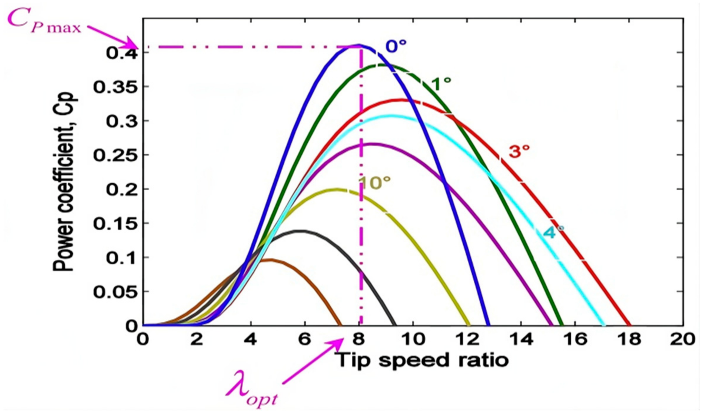
quantifies the proportion of energy derived from the wind and is determined by the variables λ and β (
Figure 2). The value of the TSR (λ) could be calculated using the following method:
The
dictates the energy output from WTs. It is determined by the
β and λ for a given set of conditions. The calculation of
is based on specific formulas, as outlined below. The power coefficient is computed using:
2.3. FSR Design
The rectifier topology can be decomposed into two equivalent sub-rectifier structures, namely the upper and lower rectifiers, to facilitate its analysis and control design. The upper rectifier is formed by the upper and middle switching devices, whereas the lower rectifier is composed of the middle and lower switching devices. This structural decomposition allows the converter to be interpreted as a modular multilevel-like configuration, simplifying its modeling and enabling the application of well-established control techniques.
The dynamic behavior of the converter is comparable to that of conventional power electronic rectifiers; therefore, standard control strategies can be effectively applied. In this work, a PWM technique is adopted to regulate the switching states and ensure proper voltage and current control. This approach provides improved flexibility in shaping the output waveforms and reducing harmonic distortion.
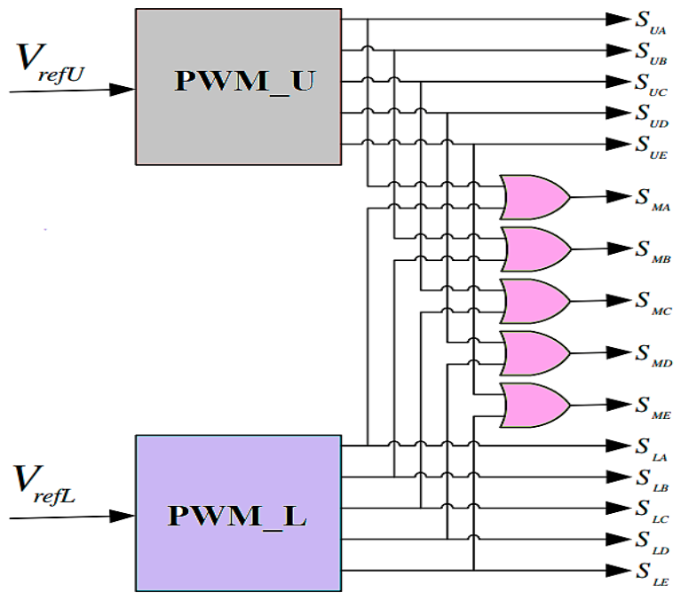
It is important to note that the gating signal of the middle switch is not generated independently; instead, it is obtained through a logical combination of the upper and lower switch control signals using an exclusive OR (XOR) logic gate, as illustrated in
Figure 3 [
25]. This logic-based implementation ensures coordinated switching operation, reduces control complexity, and enhances the reliability of the overall converter operation.
The rectifier’s switch function
might be elucidated in this manner:
Regarding the operating principle of the proposed inverter, each converter leg can operate in three distinct switching states, enabling the generation of a three-level output voltage waveform. This multilevel capability provides greater flexibility in voltage synthesis compared with conventional two-level converters, resulting in improved output waveform quality, reduced voltage stress on semiconductor devices, and lower harmonic distortion. As summarized in
Table 1, the switching states are determined by the status of the upper (S
Uj), middle (S
Mj), and lower (S
Lj) power switches. Depending on the selected switching combination, the leg output voltage can assume three discrete levels: +V
dc, 0, and −V
dc. The state +1 corresponds to the application of the positive DC-link voltage to the output terminal, while the state 0 generates a zero-voltage level. The state −1 applies the negative voltage level, thereby completing the three-level operation. These switching states enable smoother voltage transitions, reducing the voltage variation rate (dv/dt) and minimizing switching-induced disturbances. Furthermore, the availability of multiple voltage levels improves the effectiveness of PWM techniques, leading to lower THD, enhanced PQ, and improved converter efficiency. Consequently, the proposed inverter structure is particularly suitable for high-power renewable energy applications, where stable operation, low switching losses, and superior dynamic performance are required.
2.4. Grid and DC Link Voltage
For the purpose of dynamic modeling and control implementation, the grid voltage is represented in the synchronous rotating Park reference frame (d–q). The use of this reference frame enables independent regulation of the direct- and quadrature-axis components, facilitating
Ps and
Qs control while reducing the complexity of the system equations. Consequently, the grid voltage components in the (d–q) frame are given by [
32]:
In this context, and represent the currents within the grid, and indicate the grid voltage, and and refer to the resistance and inductance of the grid filter, respectively. When and represent the voltage vector of the GSC, they consist of two components in the d–q axis.
Based on the d–q-axis model of the PMSG, the instantaneous
Ps and
Qs can be expressed as functions of the stator voltage and current components. These relationships constitute the basis for power regulation and control design and are given by:
Making
and
is the control strategy that is used for the GSC. Therefore, the power equations are altered in the following manner as a consequence:
The DC-link voltage serves as a critical energy buffer that electrically couples the generator-side converter (rectifier) with the grid-side inverter through the DC-link capacitor. In the considered system, it also interfaces with the transformer on the grid side, ensuring proper power transfer and voltage adaptation between the generation and grid stages. This intermediate stage plays a key role in decoupling the dynamics of the generator from those of the grid, thereby enhancing controllability and system stability.
The dynamic behavior of the DC-link voltage can be derived based on the instantaneous power balance principle, assuming ideal converter operation and neglecting switching and conduction losses [
33]. Under this assumption, the variation in the DC-link voltage is directly related to the difference between the input power supplied by the generator-side converter and the output power delivered to the grid-side inverter through the capacitor energy storage. Consequently, any imbalance between these powers results in charging or discharging of the DC-link capacitor, which governs the transient response of the entire energy conversion system.
Accurate regulation of the DC-link voltage is therefore essential to ensure stable operation, prevent voltage fluctuations, and maintain reliable power exchange between the generator and the grid under varying operating conditions.
3. Designed FFOBC
3.1. MSC Control Design
FC is a generalization of classical integer-order calculus to non-integer (fractional) orders, providing additional degrees of freedom and the ability to model memory and hereditary properties inherent in many physical systems. Several equivalent formulations of fractional derivatives exist in the literature, with the most commonly used being the Riemann–Liouville, Grünwald–Letnikov, and Caputo definitions.
In this study, the Caputo definition is adopted due to its practical advantages in physical modeling and control system design, particularly its compatibility with classical initial conditions expressed in integer-order form. This makes it more suitable for engineering applications compared to other formulations [
34]. Accordingly, the Caputo fractional derivative is used throughout this work and is expressed as follows:
where
represents the gamma function,
denotes the order, and
refers to the integer order calculus of the function, with
being less than or equal to
and a being less than
.
Lemma 1. Suppose is a function that is both continuous and differentiable, then: Transforming Equation (3) into a form that involves fractional order: Let us define the following error terms:
q-axis current following error, Speed following error, x-axis current following error, d-axis current following error, y-axis current following error. Equation (17) illustrates this point.
- ✓
Step 01:
The control scheme of the PMSG system is developed based on the BC methodology, as described in the MM. In this framework, the control design is carried out recursively by stabilizing each subsystem through appropriately defined Lyapunov functions, ensuring overall system stability.
The fractional-order derivative (FOD) of the speed tracking error is computed using the formal definitions of fractional calculus, as presented in Equations (16) and (17) [
35,
36]. This formulation introduces memory and hereditary properties into the control structure, which more accurately reflects the dynamic behavior of the PMSG system compared to conventional integer-order approaches. As a result, the use of fractional-order differentials enhances the flexibility of the controller design, improves transient performance, and increases robustness against parameter uncertainties and external disturbances.
To analyze the stability of the developed fractional-order BC method, the following fractional Lyapunov candidate is chosen:
. In this section, we extend the direct Lyapunov method to fractional-order systems, yielding Mittag–Leffler stability [
37,
38]:
According to Equation (20) previously referenced, the necessary q-axis current may be configured as outlined below:
By substituting Equation (20) into Equation (19), and according to the Fractional Mittag-Leffler stability theorem [
38], the tracking errors asymptotically converge to the origin:
This demonstrates the first step’s stability.
- ✓
Step 02:
When the q-axis current satisfies the condition defined in the previous equation, the fractional-order derivatives of the d-axis and q-axis currents can be formulated based on the corresponding current-tracking errors. This objective is achieved by employing the fractional-order differential definitions together with the mathematical formulations presented in Equations (16) and (17). By incorporating fractional-order calculus, the proposed controller exploits the system’s memory and hereditary properties, providing additional degrees of freedom compared with conventional integer-order approaches. Consequently, the derived fractional-order current dynamics enable more accurate tracking of the reference currents while improving robustness against parameter uncertainties and external disturbances. Moreover, the proposed formulation dynamically adjusts the d-q current components to minimize tracking errors, enhance transient performance, reduce SSE, and suppress undesirable oscillations. As a result, the controller ensures smoother current regulation, improved stability, and superior dynamic behavior of the ES under both normal and varying operating conditions.
The fractional-order derivative currents form:
The speed error dynamics formulation could be updated in the following manner:
To evaluate the stability of the proposed fractional-order backstepping controller, we introduce the following fractional Lyapunov function candidate, denoted as
. Furthermore, leveraging Mittag–Leffler-based stability analysis [
37,
38], the fractional-order time derivative of the Lyapunov function is determined using Equations (23)–(27).
After a thorough analysis and careful consideration, the control law chosen to ensure stability in the PMSG system is as follows:
By replacing the given expressions from Equations (29)–(32) with Equation (28), it can be demonstrated that the FOD of the variable
is proven to be less than or equal to 0. Nevertheless, this condition holds only if the factors
are all negative. The mathematical derivation and the application of Equation (28) show that the FOD of
displays non-positive values, indicating a stable or decreasing behavior of this variable, given that the factors
are negative.
This demonstrates the steps’ (1 + 2) stability.
3.2. FL Control System
In nonlinear control systems, the use of constant-gain control strategies presents several inherent limitations, particularly when the controlled system operates under varying conditions and is subject to parameter uncertainties, external disturbances, and nonlinear dynamics. Although fixed-gain controllers are attractive due to their simplicity and ease of implementation, their performance may deteriorate significantly when applied to complex energy conversion systems characterized by highly dynamic operating environments.
One of the primary drawbacks of constant-gain controllers is their limited adaptability to changes in system dynamics. In practical applications, system parameters may vary due to temperature fluctuations, component aging, magnetic saturation effects, mechanical stress, or load variations. Under such circumstances, a gain value optimized for a specific operating condition may no longer provide satisfactory control performance, resulting in degraded tracking accuracy and reduced robustness [
39].
Furthermore, the performance of fixed-gain controllers is often inconsistent across different nonlinear operating regions. Nonlinear systems typically exhibit distinct dynamic characteristics depending on the operating point. Consequently, a gain that ensures acceptable performance in one region may become inadequate in another, leading to increased SSE, slower transient response, or even instability under severe operating conditions [
40]. This issue becomes particularly critical in renewable energy conversion systems, where operating conditions continuously vary according to environmental factors such as WS fluctuations and grid disturbances.
Another significant limitation is the increased sensitivity to external perturbations and model uncertainties. When operating outside their nominal design range, constant-gain controllers may exhibit either excessive responsiveness or insufficient corrective action. Excessively high gains can amplify measurement noise and induce undesirable oscillations, whereas low gains may reduce disturbance rejection capability and compromise system responsiveness [
41].
In addition, fixed-gain control schemes may suffer from oscillatory behavior and stability degradation in nonlinear systems. Since the controller parameters remain unchanged regardless of the system state, the control action may not adequately account for variations in damping characteristics, nonlinear couplings, and transient operating conditions. As a result, prolonged oscillations, overshoots, chattering phenomena, and even instability may occur, particularly in systems with strong nonlinearities and rapid dynamic changes [
42].
To overcome these limitations, adaptive and intelligent control methodologies have gained considerable attention in recent years. Techniques based on FL, neural networks, optimization algorithms, and fractional-order control provide enhanced adaptability by continuously adjusting control parameters according to the system’s operating conditions. Such approaches improve tracking accuracy, disturbance rejection capability, robustness against parameter variations, and overall dynamic performance, making them particularly suitable for modern renewable energy conversion systems and power electronic applications.
Concerns have also been raised regarding the tracking accuracy of constant-gain control strategies. When required to follow a reference signal under rapidly changing operating conditions, fixed-gain controllers may struggle to maintain optimal performance due to their limited ability to dynamically adapt to variations in system behavior. This often results in degraded tracking precision, increased SSE, and reduced robustness against disturbances [
43].
To overcome these limitations, FL control techniques have been widely recognized as one of the most effective intelligent approaches for enhancing system performance. FL-based controllers offer several advantages that significantly improve control effectiveness and adaptability. First, they provide enhanced flexibility by enabling rule-based decision-making that can be tailored to complex nonlinear systems. Second, FL controllers have the ability to automatically adjust control gains in real time based on error signals and their rate of change, ensuring continuous adaptation to varying operating conditions. This adaptive capability is essential for maintaining consistent performance under uncertainties, parameter variations, and external disturbances [
44,
45].
In addition, FL-based controllers exhibit strong robustness against system uncertainties. By utilizing linguistic variables, membership functions, and rule-based inference mechanisms, they are able to effectively handle imprecise, noisy, and incomplete information, which is commonly encountered in practical engineering systems. This makes them particularly suitable for renewable energy conversion systems, where environmental conditions such as WS and load demand are inherently unpredictable.
Moreover, FL techniques demonstrate superior performance in nonlinear control applications compared with conventional linear control strategies. Their nonlinear mapping capability allows them to capture complex system dynamics and ensure improved stability and tracking performance across a wide operating range. As a result, FL controllers are capable of maintaining accurate reference tracking while enhancing dynamic response characteristics.
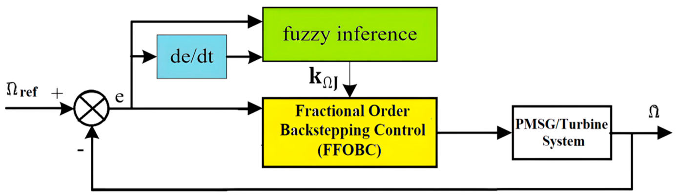
Finally, FL controllers are highly effective in managing tracking errors by incorporating both the error signal and its derivative into the control decision process. This enables the system to recognize error trends and anticipate future deviations, allowing proactive adjustment of control actions. Consequently, overshoot is reduced, settling time is improved, and overall system response is significantly enhanced. The proposed FL-based control structure is illustrated in
Figure 4, highlighting its role in improving system performance and ensuring reliable operation under varying conditions.
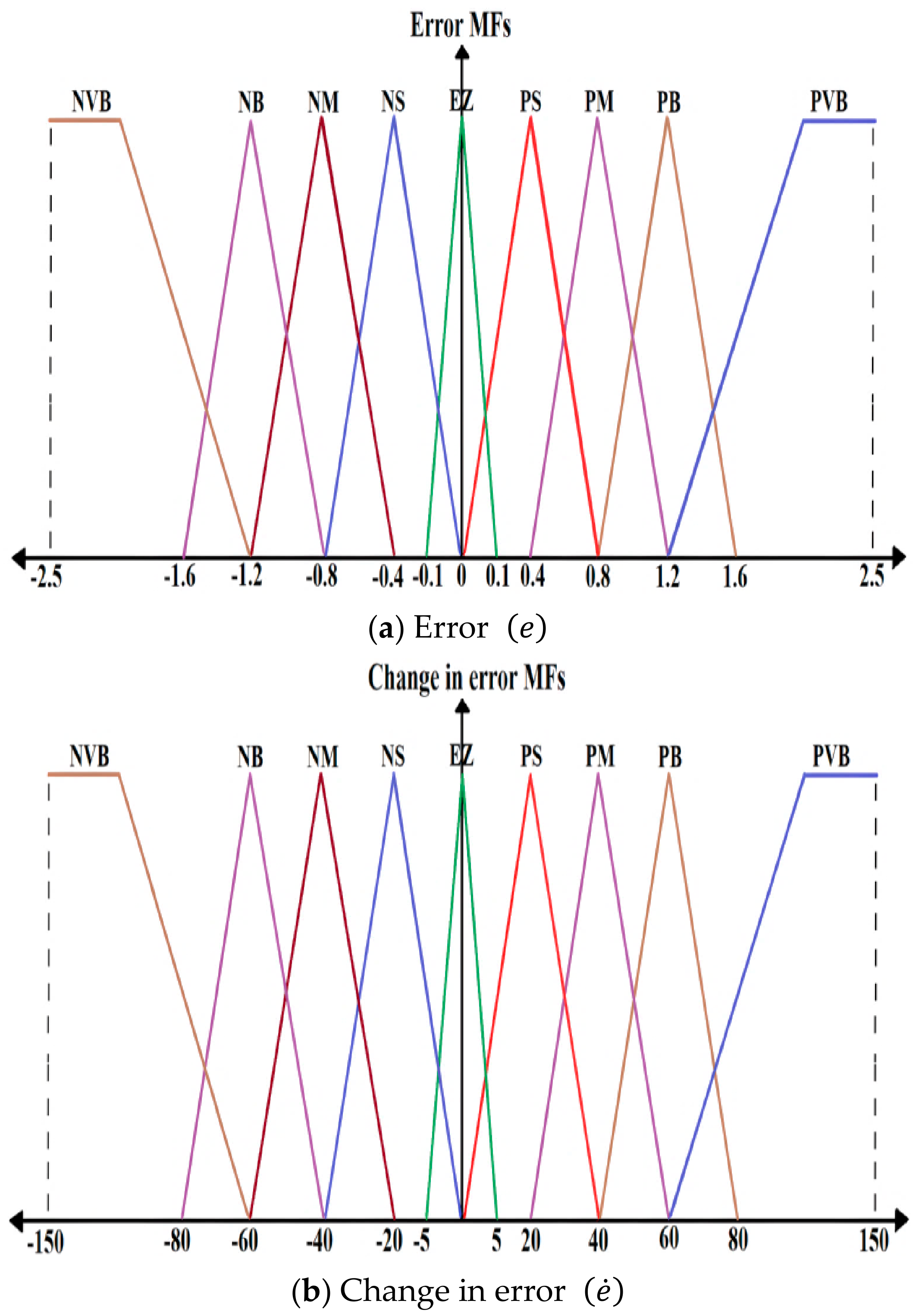
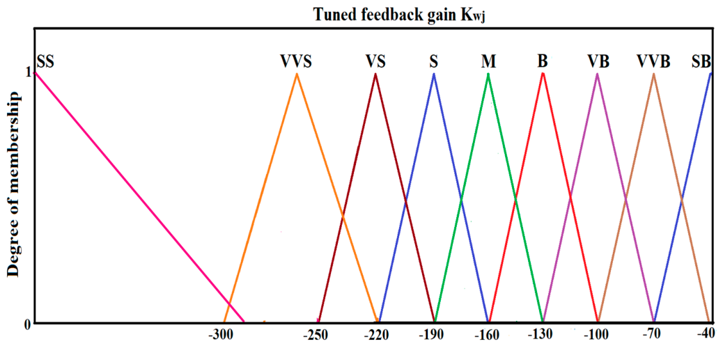
The FL approach rules could be expressed as the correlation between the input linguistic variables
and
and the output linguistic variable
. The input linguistic variable is defined by the utilization of nine membership functions for the control approach, ensuring the stability of the system.
Figure 5 and
Figure 6 depict the membership functions of the input linguistic variables
and
, as well as the output linguistic variable
. The control technique is outlined in
Table 2. This research considers triangle membership functions, as seen in
Figure 5 and
Figure 6.
3.3. GSC Control Design
Transforming Equations (10) and (13) into a form that involves fractional-order control [
31]:
The subsequent error terms will be defined as:
: DC-link voltage following error,
: d-axis current following error, and
: q-axis grid current following error. Equation (29) illustrates this point.
The control ES of the GS system is constructed utilizing the BC approach, as outlined in the MM. The FOD of the DC-bus voltage following error is determined by utilizing the definitions of fractional-order differentials through Equations (32) and (33) [
35,
36].
In this part, we select the following fractional Lyapunov candidate: .
In particular, the present section generalizes the classical direct Lyapunov approach to fractional-order dynamical systems, thereby enabling the establishment of Mittag–Leffler stability as characterized in [
37,
38]. Accordingly, Equation (34) is employed to compute the FOD of the Lyapunov function.
As indicated by Equation (35) previously referenced, the necessary q-axis current can be configured in the subsequent manner:
By substituting Equation (36) into Equation (35) and invoking the fractional Mittag–Leffler stability theorem, it follows that the tracking errors asymptotically converge to the origin.
The main objective of this control strategy is to synthesize a voltage control law based on the direct (d-axis) and quadrature (q-axis) current tracking errors in order to regulate and monitor the output power of the PMSG. This is achieved by incorporating fractional-order calculus into the control design, as defined in Equations (32) and (33), which provide the mathematical foundation for the fractional-order differential operators.
By utilizing these fractional-order derivatives, the proposed controller generates FOD current dynamics that enhance the tracking capability of the system. Consequently, the d–q axis current components are adaptively adjusted to ensure accurate convergence toward their reference values under varying operating conditions. Unlike conventional integer-order approaches, the fractional-order formulation introduces additional degrees of freedom and memory effects, allowing a more precise representation of the inherent dynamics of the ES.
As a result, the proposed method improves transient response, enhances robustness against parameter variations and external disturbances, and ensures smoother control action in the regulation of PMSG power output.
The reference current
formulation could be updated in the following manner:
The fractional-order derivative currents form:
The DC-link voltage error dynamic formulation could be updated in the following manner:
We introduce the following fractional Lyapunov function candidate, denoted as
. Moreover, through a Mittag–Leffler-based stability analysis, the corresponding FOD of V
2 is obtained using Equations (38)–(40).
After performing an extensive study and giving careful calculations, the control law selected to maintain stability in the power-injecting system is as follows:
By replacing the given expressions from Equations (44) and (45) with Equation (43), it can be demonstrated that the FOD of the variable
is proven to be less than or equal to 0. Nevertheless, this condition holds only if the factors
are all negative. The mathematical derivation and the application of Equation (43) show that the FOD of
displays non-positive values, indicating a stable or decreasing behavior of this variable, given that the factors
are negative.
This demonstrates the system’s stability.
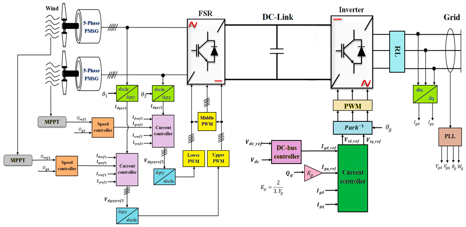
Figure 7 illustrates the overall architecture of the proposed ES, including the control structure associated with the two power converters. The system consists of two WTs driven by PMSGs, where each WT is equipped with an independent MPPT algorithm to ensure optimal extraction of available WE under varying WS conditions. The generated power is processed through dedicated power electronic converters, which are regulated by the proposed control strategy to guarantee stable operation and efficient power transfer.
In addition, a phase-locked loop (PLL) is integrated into the control scheme to accurately estimate the grid voltage phase angle and frequency, ensuring proper synchronization between the converters and the utility grid. The PLL contributes significantly to improving the dynamic response, stability, and robustness of the overall system, particularly under grid disturbances and parameter uncertainties. Furthermore, the coordinated operation of the MPPT units, PLL, and converter controllers enables enhanced PQ, reduced current harmonics, and reliable energy conversion performance across a wide range of operating conditions.
Stability assessment is commonly performed using two complementary methodologies: Lyapunov-theoretic analysis based on Mittag–Leffler stability and Bode plot analysis. Lyapunov-based methods typically require the formulation of suitable Lyapunov functions and involve complex analytical derivations, which can be mathematically intensive and prone to error. In contrast, the Bode plot provides a graphical and more intuitive means of analyzing system behavior in the frequency domain, without requiring extensive computations.
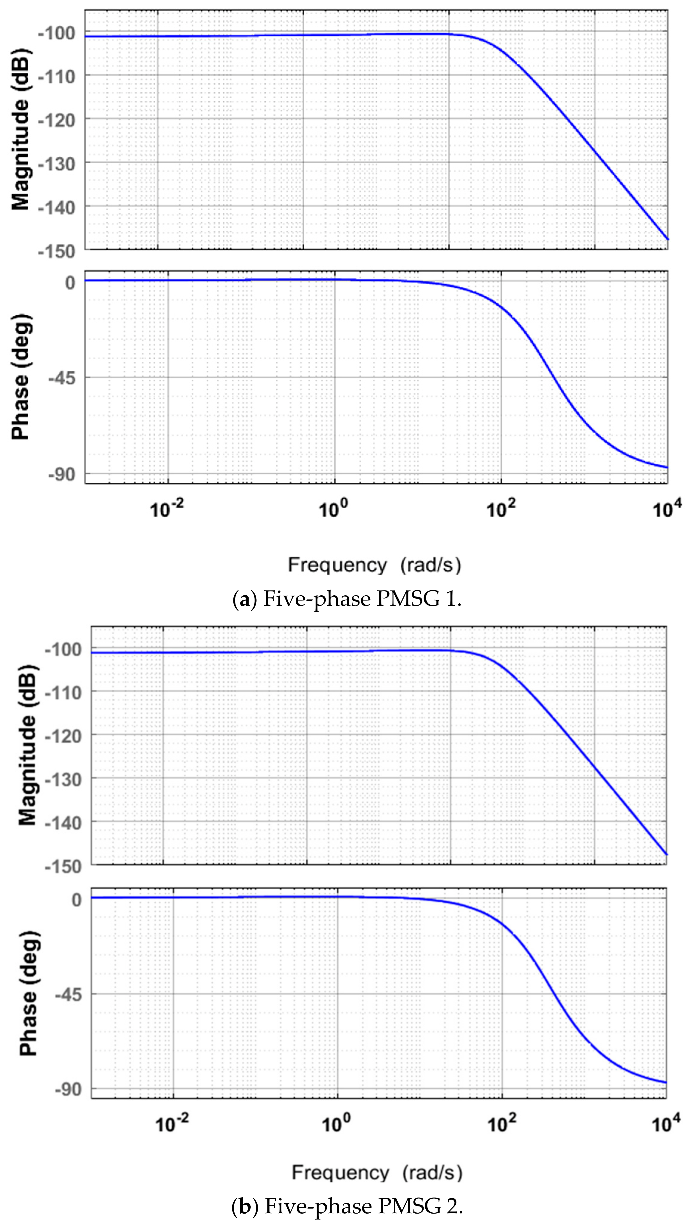
In this study, the Bode plot is employed to analyze the dynamic behavior of the proposed FFOBC scheme. The frequency responses corresponding to the two PMSG systems are presented in
Figure 8, showing both magnitude and phase characteristics.
It should be noted that negative magnitude values in dB indicate signal attenuation and do not, by themselves, confirm system stability. Therefore, stability is assessed based on standard frequency-domain criteria such as gain margin, phase margin, and crossover frequencies. As observed in
Figure 8, the magnitude decreases with increasing frequency, while the phase shifts progressively, which is consistent with typical system behavior.
For the proposed FFOBC, the magnitude ranges approximately from −102 dB to −150 dB, and the phase varies from 0° to −90° over the analyzed frequency range. These results are interpreted in the context of established control theory metrics to evaluate system performance and stability.
4. Results
This section implements the control schemes for the 5-ph PMSGs and utilizes MATLAB for this purpose. Consequently, the following parameters were utilized: A total of two distinct experiments are implemented to validate the advantage of the suggested FFOBC over the SMC.
4.1. Test 1
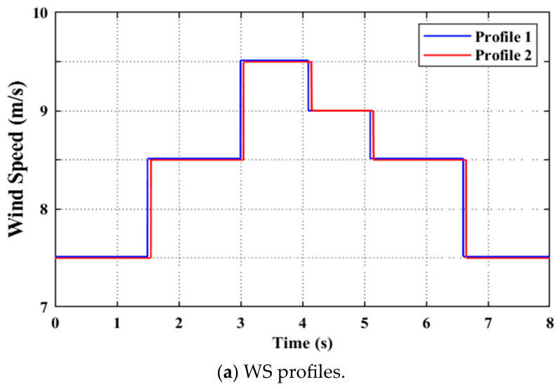
The initial test evaluates the proposed FFOBC approach, employing a WS form utilized in a series of steps for this objective. The utilized WS is illustrated in
Figure 9a.
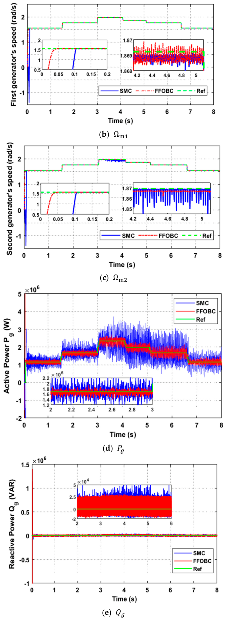
Figure 9b,c illustrates the combined rotational speed of both PMSGs when utilizing both approaches (FFOBC and SMC). The speed of the two generators is observed to manifest as a change in WS, with the FFOBC demonstrating superior stability and a rapid dynamic response compared to the SMC approach.
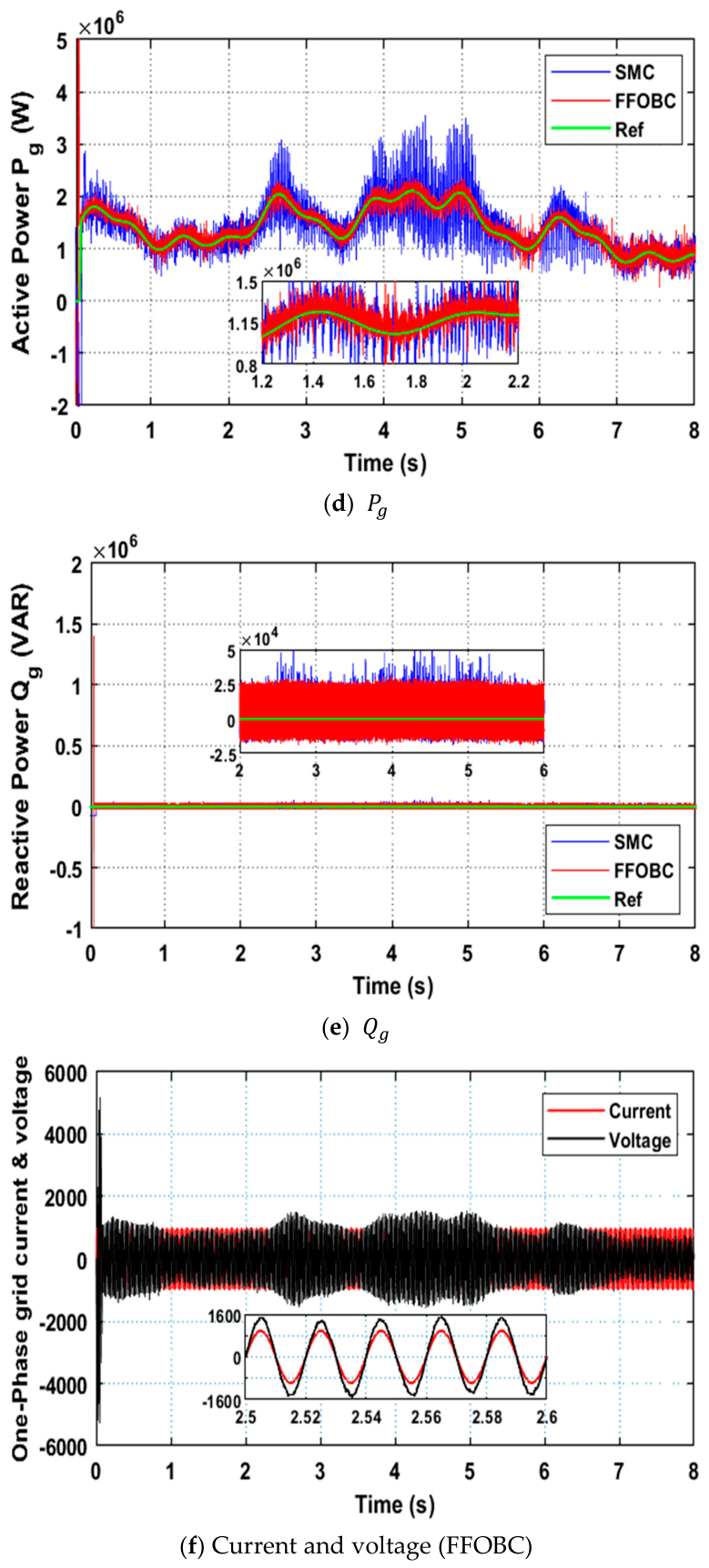
Figure 9d presents the variation in
Ps for the two controllers. The
Ps varies according to changes in the WS, thereby demonstrating a rapid dynamic response from both control systems. It has been observed that both approaches are subject to fluctuations. The fluctuations are considerably more substantial when the SMC is employed in comparison to the FFOBC. The
Qs of the two regulators are illustrated in
Figure 9e, indicating that this power remains unchanged over time, consistently maintaining a value of 0 VAR. It is observed that the SMC results in larger ripples when compared to the FFOBC.
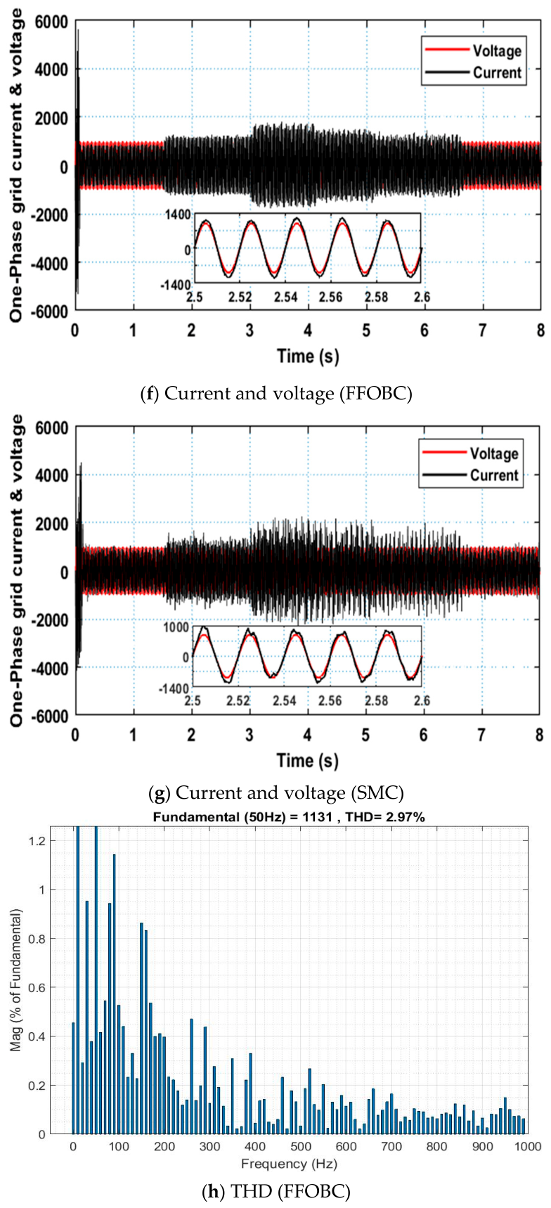
The one-phase grid voltage and current for each of the controls are illustrated in
Figure 9f and
Figure 9g, respectively, where ripples are evident for the two controls. Furthermore, these estimates demonstrate variability in response to variations in WS, as the current adopts a sinusoidal shape, thereby exhibiting enhanced quality when employing the FFOBC in comparison to the SMC approach. The observed correlation between the current and voltage for both methods demonstrates a strong unit power factor.
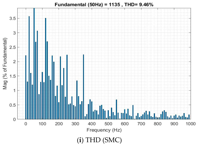
The test indicated that the THD of current was estimated at 9.46% for the SMC approach and 2.97% for the FFOBC approach, as illustrated in
Figure 9h,i. The FFOBC exhibited a substantial reduction in THD when contrasted with the SMC method. The proposed FFOBC technique demonstrated a substantial reduction in THD, reaching approximately 68.60%, thereby substantiating its efficacy and capacity to refine the current. The amplitude value of the fundamental signal (FS) for the two approaches is nearly identical, with a slight advantage for the SMC over the FFOBC, recording values of 1135 A and 1131 A for the conventional and suggested approaches, respectively.
The data in
Table 3 highlight the improvements achieved by the proposed FFOBC method over the conventional SMC in regulating the
Ps and
Qs of PMSG. The FFOBC system significantly reduces power ripple compared to the SMC system, indicating smoother performance under stable conditions. For
Ps, ripple decreases from 800,000 watts in the SMC system to 300,000 watts in the FFOBC system, representing a 62.5% improvement. Similarly, for
Qs, ripples decrease from 60,000 VAR to 40,000 VAR, representing a 33.33% improvement. This reduction in oscillations reflects the enhanced stability and high control accuracy achieved through fuzzy tuning and fractional calculus.
The SSE values also show a significant improvement. For Ps, the SSE decreased from 60,000 W to 15,000 W (a 75% decrease), and for Qs, from 30,000 V to 10,000 V (a 66.66% decrease). These results confirm that FFOBC achieves more accurate tracking of reference power values at steady state, contributing to improved reliability and consistent performance. Both controllers exhibit similar overshoot behavior. While FFOBC shows a slight change of −2.85% in Ps overshoot (a slight increase from 3.4 MW to 3.5 MW), Qs overshoot remains constant at 1.4 MW, indicating that FFOBC maintains similar transient performance in this respect.
The response time (RT) improved significantly in the FFOBC algorithm, decreasing from 0.12 s to 0.08 s for effective energy (33.33% faster) and from 0.11 s to 0.076 s for Qs (31% faster). This demonstrates that the FFOBC algorithm provides a faster dynamic response, enabling the system to reach a stable state more quickly after disturbance or reference changes.
Overall, the results clearly demonstrate that the FFOBC method outperforms the conventional SMC method in almost all evaluated performance metrics. The combination of the FL method and fractional calculus improves adaptability, accuracy, and switching speed, resulting in smoother power output and enhanced stability. Although the overshoot remained largely constant, the large reductions in ripple, SSE and response time confirm that the FFOBC method provides a more stable, responsive and efficient control strategy for PMSG-based WE systems.
4.2. Test 2
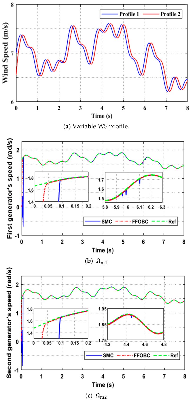
The suggested FFOBC method is evaluated in the second test (robustness test), which involves altering the parameters of system
and
on each machine. This test employs a different form of WS change than the first test, which utilized a fluctuation model (see
Figure 10a).
As illustrated in
Figure 10b,c, the velocity profiles for both generators are presented. An analysis of the data reveals that the SMC approach exhibits ripples in the generator speed waveform and a significant RT. This phenomenon can be attributed to the substantial reliance of the SMC on the sign function. The dynamic nature of system features poses challenges for the SMC method in effectively regulating generator speed, resulting in an increased occurrence of undesirable ripples in the speed profile. The FFOBC demonstrates a notably superior performance. The generator velocity utilizing the FFOBC consistently aligns with the reference value, exhibiting exceptional stability and remaining unaffected by variations in system parameters.
Figure 10d,e illustrates the variation in power over time for both of these controls. Despite adjustments made to the parameter values, the capabilities maintain a strong alignment with the reference values, a finding that is encouraging. The
Ps consistently aligns with the variations in WS, exhibiting greater ripples when employing the SMC strategy in contrast to the FFOBC. The constant
Qs persist in the face of variations in WS, maintaining a constant value of 0. Furthermore, the proposed FFOBC strategy demonstrates a reduced degree of ripples when compared to the SMC method, yielding results that are consistent with the preceding evaluation.
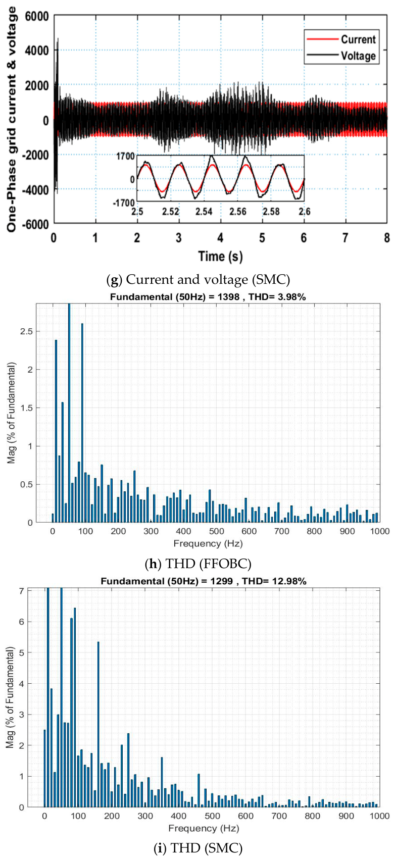
The one-phase grid voltage and current for each control method indicate that the current retains a waveform that aligns with variations in WS for both controls, displaying ripples. The electric current waveform is sinusoidal for both controls, with the FFOBC technique demonstrating a qualitative advantage, as illustrated in
Figure 10f,g. Furthermore, the observed correlation between the current and voltage for both methods indicates a robust unit power factor.
The THD value for the two algorithms is presented in
Figure 10h,i. The present THDs were recorded at 12.98% for the SMC approach and 3.98% for the FONF method, respectively. Consequently, both strategies have increased the value of THD in comparison to the prior test, with an estimated augmentation of 1.01% for the FFOBC technique and 3.52% for the SMC approach. This percentage indicates that, despite variations in ES parameters, the quality of the current is superior when employing the FFOBC approach in comparison to the SMC approach by 69.33%. The amplitude value of the FS (50 Hz) for the two approaches is nearly identical, with a notable advantage for the FFOBC over the SMC, recording values of 1398 A and 1298 A for the conventional and suggested approaches, respectively. This amplitude value indicates an enhancement in performance when compared with the preceding test for the FFOBC technique and a reduction in performance for the SMC method.
Table 4 provides a comparative evaluation of the SMC and FFOBC control methods in regulating the outputs of the
Ps and
Qs of the PMSG under test conditions 2. The results show that the FFOBC method consistently improves PQ, steady-state accuracy, and dynamic response compared to the conventional SMC.
The proposed FFOBC system demonstrates a significant reduction in power fluctuations. For Ps, ripples decrease from 700,000 W (SMC) to 250,000 W (FFOBC), representing a 62.28% improvement. For Qs, fluctuations decrease from 56,000 VAR to 40,000 VAR, achieving a 28.57% reduction. This indicates that the FFOBC system provides smoother operation in a stable state, effectively reducing power output fluctuations and improving overall stability.
The FFOBC system achieves a significant reduction in SSE efficiency compared to the SMC system. For Ps, the SSE efficiency decreases from 60,000 W to 13,000 W, representing a 78.33% improvement. Similarly, for Qs, the SSE efficiency decreases from 24,000 VAR to 10,000 VAR, a 58.33% improvement. These results confirm that the proposed controller improves tracking accuracy and ensures better conformance to reference values. Both control schemes exhibit identical bypass characteristics, with no significant improvement (0%). The bypass remains at 3.4 MW for Ps and 1.4 MVAR for Qs. This indicates that although FFOBC does not further reduce the bypass, it maintains stable transition behavior comparable to that of SMC.
The RT was significantly improved in the FFOBC system. For Ps, the response time decreased from 0.123 s to 0.081 s (34.14% faster), while for Qs it decreased from 0.11 s to 0.0765 s (30.45% faster). These results demonstrate the superior dynamic response and adaptability of the FFOBC controller in handling system changes and disturbances.
Overall, the results in
Table 4 confirm that the FFOBC method achieves significant improvements in steady-state performance and transient response compared to the conventional SMC system. The integration of the FL method enhances the controller’s adaptability, while fractional calculus contributes to more precise control and smoother responses. The FFOBC method effectively reduces ripple and SSEs, minimizes response time, and maintains consistent overshoot levels. These improvements indicate that the proposed FFOBC system offers a more robust and efficient control strategy for PMSG-based WE systems, ensuring higher PQ and dynamic stability under varying operating conditions.
Table 5 represents the comparative sensitivity analysis of performance indices between Test 1 and Test 2. The comparative results between Test 1 and Test 2 provide valuable insight into the sensitivity and robustness of the proposed control system under parameter variations and different WS profiles. Overall, the system demonstrates a stable behavior with limited degradation, confirming its robustness.
For Ps, a reduction in fluctuations of approximately 12.5% is observed in Test 2 compared to Test 1, indicating improved damping characteristics under parameter variation conditions. However, the SSE remains unchanged, while a slight increase of 2.5% in response time is recorded, suggesting a marginal slowdown in dynamic response under the second test scenario. Importantly, overshoot remains constant in both tests, confirming that transient peak behavior is not significantly affected by system parameter variations.
For Qs, the system exhibits further improvements in steady-state performance, with SSE reduced by 20% and fluctuations decreased by approximately 6.67%. These results indicate that Qs control is more sensitive to parameter variations and benefits more noticeably from the modified operating conditions in Test 2. Similarly to Ps, overshoot and response time remain largely unchanged, highlighting consistent transient behavior across both scenarios.
Overall, the comparative analysis confirms that the system maintains strong robustness against uncertainties, with improvements primarily observed in steady-state accuracy and power smoothing, while transient peak characteristics remain invariant. This indicates that the proposed control strategy is more effective in enhancing steady-state performance than altering transient response dynamics.
As illustrated in
Table 6, a comparative analysis of the completed search with other methodologies (references [
46,
47,
48]) is provided with regard to THD of current, robustness, simplicity, and stability. The findings of this study demonstrate that the implementation of the FFOBC approach resulted in a significant reduction in THD values when compared to several control strategies, including MPC, FBSC, and FSMC. The proposed FFOBC technique introduces complexity issues for certain existing controls, including MPC, which is a disadvantage. Notwithstanding its inherent complexity, the FFOBC method exhibits numerous advantages over alternative control approaches, such as SMC. In terms of robustness, the FBC approach demonstrates superior resilience in comparison to certain existing controls, thus indicating the potential of the developed FFOBC as a solution within the domain of control.
Table 7 provides a quantitative comparison between the FFOBC developed in this study and the technique mentioned in reference [
29] across multiple tests and performance indicators, namely, energy ripples, overshoot, RT, and SSE for both
Ps and
Qs of the PMSG. FFOBC exhibits a significantly greater reduction in energy ripples compared to the method described in [
29].
In Test 1, FFOBC achieved improvements of 62.28% (
Ps) and 28.57% (
Qs), compared to only 16.66% and 2.50% in [
29]. In Test 2, the improvements remained strong at 62.5% (
Ps) and 33.33% (
Qs) for FFOBC, compared to 13.33% and 6.66% for [
29].
The results show that FFOBC reduces Ps and Qs fluctuations approximately 3–5 times more effectively, confirming its superior ability to stabilize PMSG output and suppress fluctuations during steady-state operation.
In both tests 1 and 2, the FFOBC’s overshoot performance was good or slightly better than the approach described in [
29]. The FFOBC maintains a 0% overshoot for
Qs and close to 0% (−2.85%) for Ps, which is better than the moderate overshoot (4–7.41%) observed in [
29]. This indicates that the FFOBC design effectively controls transient heights and ensures a smoother dynamic transition without additional overshoot penalties.
The FFOBC system exhibits a significantly faster RT to reach a steady state compared to [
29]. In Test 1, the FFOBC system improves RT by 34.14% (
Ps) and 30.45% (
Qs), compared to 14.28% and 15.05% in [
29]. In test 2, the FFOBC system’s results (33.33% Ps, 31%
Qs) again outperform those of [
17] (15.22%
Ps, 15.85%
Qs).
These results confirm that the proposed method improves the control response by more than double the rate achieved in the previous study, ensuring faster system stabilization under varying wind conditions.
In both test cases, the FFOBC also demonstrated a superior reduction in SSE. In Test 1, the FFOBC achieved an improvement of 78.33% (
Ps) and 58.33% (
Qs), while [
29] achieved only 16.66% (
Ps) and 6.66% (
Qs). In Test 2, the proposed controller again outperformed [
29] with reductions of 75% (
Ps) and 66.66% (
Qs), compared to 20% (
Ps) and 20% (
Qs). This significant improvement in SSE performance reflects the FFOBC’s ability to accurately track reference signals and maintain precise operation under stable conditions.
The comparison clearly shows that the FFOBC method significantly outperforms the reference control technique [
29] in all key performance metrics and test scenarios. FFOBC achieves higher ripple suppression, faster dynamic response, and more accurate steady-state performance while maintaining a stable and minimal overshoot level. This superior performance can be attributed to the synergistic integration of FL method and fractional calculus within the BC architecture. Fuzzy adaptation enhances nonlinear processing and gain control, while fractional elements improve response smoothness and stability. Therefore, FFOBC provides a robust, adaptive, and high-performance control framework for PMSG-based WT systems, surpassing traditional methods documented in previous studies such as [
29].
5. Discussion
The obtained results from the two conducted tests clearly demonstrate the superior performance of the proposed FFOBC strategy compared to the conventional SMC for the multi-machine PMSG-based WE system.
In Test 1, under a stepwise WS profile, the proposed FFOBC exhibits enhanced dynamic behavior characterized by faster speed tracking and improved stability for both PMSGs. The power responses (Ps and Qs) show significantly reduced oscillations compared to the SMC, indicating smoother energy conversion and better damping of system dynamics. Although both controllers are able to follow WS variations, the FFOBC consistently provides lower ripples in Ps and Qs.
The grid current quality is also significantly improved using the proposed method. The current waveforms become more sinusoidal with reduced distortions, which is confirmed by the substantial reduction in THD from 9.46% (SMC) to 2.97% (FFOBC), corresponding to an improvement of approximately 68.60%. This confirms the effectiveness of the proposed control in enhancing PQ at the grid side.
Furthermore, quantitative performance indicators highlight the superiority of FFOBC. For Test 1, power ripple reduction reaches 62.5% for Ps and 33.33% for Qs, while SSE is reduced by 75% and 66.66%, respectively. In addition, the response time is significantly improved, showing faster convergence to steady-state conditions. These results confirm that fractional-order control combined with fuzzy logic enhances system adaptability, reduces oscillations, and improves tracking precision.
In Test 2 (robustness test), where system parameters Rs and Lm are varied, the FFOBC maintains stable performance, confirming its robustness against parameter uncertainties. Unlike SMC, which exhibits noticeable ripples and slower response due to its strong reliance on the sign function, the proposed method ensures smooth speed tracking and stable power regulation even under system perturbations.
The robustness of FFOBC is further confirmed by THD analysis, where the current distortion remains significantly lower (3.98%) compared to SMC (12.98%), maintaining an improvement of approximately 69.33%. Moreover, performance indices show consistent improvements in ripple reduction (62.28% for Ps and 28.57% for Qs), SSE reduction (78.33% and 58.33%), and faster response time (up to 34.14%). Importantly, both controllers maintain similar overshoot levels, indicating that the improvement is mainly achieved in steady-state accuracy and dynamic response rather than transient peak behavior.
Overall, both tests validate that the proposed FFOBC strategy provides superior performance in terms of PQ, dynamic response, and robustness, making it highly suitable for PMSG-based WE systems operating under variable wind conditions and parameter uncertainties.