Abstract
Proton exchange membrane fuel cell (PEMFC) hybrid vehicles offer a long driving range but are heavily dependent on energy management strategies (EMS). Traditional EMS methods, such as rule-based approaches and optimization-based methods like model predictive control (MPC), either lack flexibility or are computationally complex and rely on prior driving experience. To overcome these limitations, this study proposes a semi-empirical approach that combines state machine (SM) and MPC in a novel hybrid EMS (SM-MPC) to optimize power distribution in a 100 kW PEMFC hybrid vehicle. The SM-MPC strategy uses SM to handle fast power fluctuations and MPC to manage slow variations, balancing real-time adaptability and efficiency. Simulation results based on the NEDC and HWFET driving cycles show that compared to the traditional MPC method, SM-MPC significantly reduces hydrogen consumption by 7.11 g (NEDC) and 1.89 g (HWFET). Additionally, the proposed method effectively maintains the state of charge (SOC) of the lithium-ion battery using a PID controller and ensures the PEMFC stack temperature remains within ±5.8 °C. Overall, the SM-MPC strategy improves energy efficiency, reduces fuel consumption, and enhances the stability of the hybrid power system, offering a promising solution for real-time energy optimization in fuel cell vehicles.
1. Introduction
The proton exchange membrane fuel cell (PEMFC) is a clean power conversion device that generates electrical and thermal energy through the electrochemical reaction of hydrogen and oxygen [1]. It has been widely applied in mobile power sources, automobiles, drones, and other devices. The power generation process produces virtually no noise and realizes no carbon emissions. However, fuel cells have relatively smooth output characteristics and may not provide sufficient power for instantaneous demands [2]. As a result, they often require supplementary power sources, such as lithium-ion batteries. A system composed of fuel cells and lithium-ion batteries forms a fuel cell hybrid power system.
Vehicles equipped with fuel-cell hybrid power systems have a better range compared to traditional vehicles [3]. However, the highly nonlinear nature of power systems composed of multiple energy sources presents design challenges for energy management strategies (EMS), particularly regarding adaptability and control robustness under various driving conditions [4]. Under this premise, advanced EMSs have a considerable effect on releasing the energy-saving potential of hybrid power systems.
Many experts and researchers have already designed various hybrid power systems and studied their energy management [5,6]. Currently, there are two mainstream types of EMS: rule-based EMS and optimization-based EMS [7]. Rule-based EMS uses deterministic or fuzzy logic strategies and is widely favored in the industry due to its simple structure and easy implementation [8]. Nevertheless, rule-based methods heavily rely on expert experience and practical operating constraints, which lack flexibility, especially when facing with complex driving conditions. Typically, rule-based methods allocate the power between the fuel cell and lithium-ion battery according to different power demand phases. This approach primarily considers the operation of a single battery, to some extent leading to fuel waste.
Optimization-based methods effectively address such issues by setting different objectives to constrain and allocate the power between the fuel cell and the lithium-ion battery [9]. Some indicators, such as the lithium battery SOC, stack temperature, and the hydrogen mass flow rate, are used as optimization objectives to balance the power distribution in hybrid power systems. Through a review of the latest research literature, global optimized-based EMS and instantaneous optimization-based EMS offer superior economic performance. The globally optimized-based EMS mainly includes dynamic programming (DP) [10], Pontryagin’s minimum principle (PMP) [11], and heuristic algorithms such as genetic algorithms (GA) [12] and differential evolution (DE) [13]. These methods intend to obtain the optimal control sequence based on known driving information. However, these strategies are limited by their computational complexity and heavy reliance on prior driving information. This makes it difficult for them to be applied in practice. In contrast, instantaneous optimization-based EMS, such as the equivalent consumption minimization strategy (ECMS) [14] and Model Predictive Control (MPC) [15], offer satisfactory control performance and have the potential for real-time applications.
ECMS uses an equivalent factor to minimize the instantaneous equivalent fuel consumption by equating power consumption with fuel consumption. However, the inability to automatically adjust internal parameters limits its adaptability to different driving conditions. Recently, Li et al. [16] proposed a preferred variant called adaptive ECMS (A-ECMS). A-ECMS adapts the equivalent factor in ECMS by obtaining several ideal driving conditions, thus enhancing robustness. However, external disturbances are not considered, making it difficult to apply in real-world, complex, and dynamic driving environments. MPC generates the optimal control input signal by defining a prediction horizon for rolling optimization, demonstrating its flexibility under different driving conditions. Recently, Touil et al. [17] investigated the impact of velocity prediction on the performance of MPC-based EMS for FCEVs. Four MPC prediction settings were tested: prescient MPC, frozen time MPC, exponentially decreasing MPC, and MPC with a Markov chain model. This research compared the results across different driving cycles to explore how prediction horizon and accuracy affect hydrogen consumption and battery charge sustainability. Jia et al. [18] proposed an energy management strategy based on a variable-step multi-step prediction MPC aimed at reducing energy losses in a fuel cell and supercapacitor hybrid energy storage system. This strategy ensured that the battery current and the supercapacitor’s SOC remained within an appropriate range.
MPC-based EMS holds great promise for achieving efficient power conversion in various hybrid electric vehicles. Therefore, MPC is considered a promising control algorithm for unlocking the energy-saving potential of FCEVs and can be deployed in onboard controllers.
This study aims to design a PEMFC hybrid power system for a 100 kW truck. The Modelica-based model is built to investigate the multi-energy flow coupling characteristics, including thermal, electrical, and hydrogen energy, of the hybrid system. Then, a hybrid method combining the proposed state machine and MPC is also used for the EMS of the 100 kW truck. The main contributions of this study are listed as follows:
- (1)
- A hybrid power system of 100 kW rated power is designed. The mathematical models of the PEMFC system, lithium-ion battery system, and other subsystems will be presented in detail. Subsequently, one-dimensional modeling of the fuel cell and zero-dimensional modeling of the lithium-ion battery will be performed using Modelica through the Dymola 2023X platform.
- (2)
- The vehicle’s power demand is divided into different stages, and a hybrid method combining the proposed state machine and MPC (SM-MPC) is proposed for the vehicle’s EMS.
- (3)
- The performance of the proposed SM-MPC EMS is validated using test data from two driving cycles, and it is compared with SM and MPC methods.
The rest of this study is organized as follows: Section 2 introduces the modeling process of the PEMFC stack and other components. In Section 3, the proposed energy management strategy will be described briefly. The simulation and evaluation analysis are discussed in Section 4. Finally, Section 5 gives the conclusion and prospectives of this study.
2. Mathematic Model of Hybrid Power System
The proposed hybrid power system mainly consists of a water-cooled PEMFC stack and a lithium-ion battery. The PEMFC is primarily used to provide stable high-power output, while the lithium-ion battery is used to deliver instantaneous and rapid power response. The balance of plant (BOP) system of the PEMFC includes a cooling water circulation subsystem and an air compressor subsystem. The associated auxiliary components are also considered, as shown in Figure 1 below:
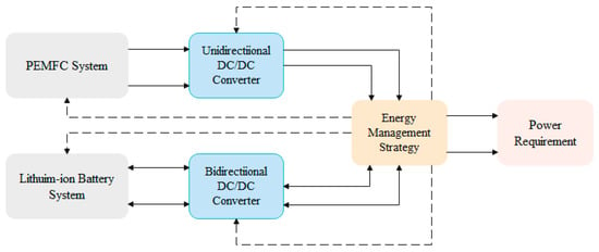
Figure 1.
Structure diagram of the proposed hybrid power system.
The dashed lines in Figure 1 represent the control signal transmission path, while the solid lines represent the direction of electrical energy transmission. In the proposed configuration, the PEMFC and lithium-ion battery jointly supply the vehicle’s required power. The PEMFC is connected in parallel to the DC bus through a unidirectional DC/DC converter, providing continuous power to the vehicle. The lithium-ion battery is connected to the DC bus via a bidirectional DC/DC converter, supplying supplementary power for the stack startup. The advantage of this configuration lies in the ability of the lithium-ion battery to assist the fuel cell system in providing supplementary power, thereby improving power output performance. Moreover, the lithium-ion battery can provide or absorb transient power demands or responses, extending the service life of the stack.
2.1. PEMFC Model
The PEMFC system is a complex, multi-input, multi-output, and multi-time-scale nonlinear system [19]. It involves various dynamic processes, such as gas flow, electrochemical reactions, gas-liquid phase transitions of water vapor, and heat exchange between channels [20]. Generally, the regulation capability of the fuel cell stack itself is limited, particularly when there are significant changes in external environmental conditions. Therefore, the design and construction of corresponding auxiliary subsystems are fundamental to ensuring the stable operation of the PEMFC stack. As shown in Figure 2, hydrogen and oxygen flow through the anode and cathode, respectively, entering the PEMFC through the flow channels. After passing through the gas diffusion layer, they enter the catalyst layer where they gain and lose electrons. The electrons generated by the electrochemical reaction flow through the external circuit, forming an electric current. Simultaneously, the heat produced is absorbed by the exhaust gases and the fuel cell itself [21].
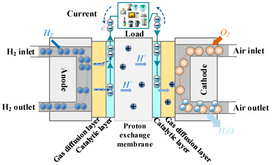
Figure 2.
Structure diagram of the PEMFC.
The interconnections among subsystems introduce complex dynamic variations in critical physical parameters. For instance, the output voltage of the stack is influenced by factors such as stack temperature, relative humidity on the anode and cathode sides, gas pressure, and external current density [22]. Additionally, the internal humidity of the stack is closely tied to its operating temperature. To ensure the long-term stable operation of the PEMFC system, it is crucial to conduct in-depth research into the physical relationships among these subsystems [23]. Consequently, constructing a comprehensive dynamic model of the PEMFC system and analyzing its dynamic characteristics are fundamental tasks.
2.1.1. Stack Voltage
For PEMFC, the cell voltage is produced by the electrochemical reaction of hydrogen and oxygen [24]. The actual output circuit voltage can be stated as Equation (1):
where indicates the Nernst open circuit voltage, is the activation polarization voltage, is the ohmic polarization voltage, and is the concentration polarization voltage.
In the model, is the theoretical reversible voltage at a certain temperature effect and pressure of hydrogen and oxygen [25]. Equation (2) gives the numerical expression while the liquid water is produced by the electrochemical reaction.
where the temperature of fuel cell is provided by the temperature calculation model described in Section 2.1.2, denotes the reference temperature ( = 298.15 K), and and are the partial pressure of anode and cathode reactants, respectively.
The activation polarization voltage mainly originates from the energy required to transfer electrons during the electrochemical reaction, as well as the energy involved in breaking or forming chemical bonds at the anode and cathode sides [26]. Therefore, activation losses exist on both the cathode and anode sides. Generally, the chemical reaction of oxygen is slower compared to the reduction reaction of hydrogen. Equation (3) is a theoretical expression according to the Butler–Volmer equation.
where , , , and are the empirical coefficient, is the oxygen concentration of cathode catalyst interface, and is the output current of the external circuit.
The ohmic polarization voltage losses consist of the electrode resistance and the internal resistance of the PEM [27]. As the equivalent membrane impedance of the PEM is the main contributor to the ohmic polarization voltage, it can be described using Equation (4):
where , , and denote the total resistance, PEM resistance, and the electrode resistance, respectively. Theoretically, the PEM resistance strongly depends on the moisture of PEM, current density, and working temperature of PEMFC.
where is the thickness of the membrane, and is the conductivity of PEM as the following formula:
where is the effective area of PEM, and is the membrane water content indicating the following equation:
where is the water activity.
The PEM must maintain a certain level of hydration to ensure efficient proton transport through the membrane. Therefore, its conductivity is related to the water content. When the water content in the membrane is at an optimal level, it not only maximizes conductivity but also effectively reduces the internal resistance of PEMFC.
The concertation polarization voltage arises from the potential difference caused by the reduction in reactant concentration as they are consumed [28]. This loss is the primary reason for the rapid voltage drop of the fuel cell stack at high current densities. The concertation polarization voltage can be described as Equation (8):
where denotes the maximum current of the PEM, R is the reaction constant, and F is the Faraday constant.
In practical application, multiple fuel cells are usually connected in series to form a stack to increase the output power. Therefore, the overall output voltage of the fuel cell stack is given by Equation (9):
where is the output voltage of the stack, and is the number of fuel cells connected in series.
2.1.2. Stack Temperature
The electrochemical reaction of a fuel cell is temperature-dependent, and the operating temperature directly affects its output power, efficiency, and service life. Both excessively high and low temperatures can lead to a decline in the performance of the cell [29]. For instance, high temperatures may cause catalyst deactivation, material aging, and internal moisture management issues, which in turn affect the long-term stability of the fuel cell. On the other hand, low temperatures can make it difficult to start the fuel cell and reduce its efficiency. Therefore, precisely controlling the fuel cell’s temperature helps maintain it within the optimal operating range, thereby improving the overall system’s efficiency and power output.
The temperature model of the PEMFC system primarily describes the dynamic process of temperature variation in the fuel cell stack, the stack cathode, the anode, and the cooling channels. In this study, a cooling system using water circulation is employed to dissipate the heat from the fuel cell stack efficiently and uniformly. This approach effectively prevents localized overheating or overcooling of the stack, allowing for better regulation of the operating temperature of the fuel cell stack [30].
The model constructed in this section includes the heat generated by electrochemical reactions, the heat carried by excess gases, the heat carried by the cooling water, and the net output power.
According to the law of energy conservation, the main energy transfer processes are described. The contributions of the kinetic and potential energy of the mass flow are relatively small compared to other energy transfers and can be neglected. The thermodynamic differential equation for the temperature of the fuel cell stack is given by Equation (10) [31]:
where is the mass of stack in kilograms, is the average specific heat capacity, stands for heat generated by the stack, is stack temperature, is the temperature dynamic change, refers to the heat flow rate generated by the reaction in the current fuel cell stack that produces water vapor, is the heat flow rate of the excess air that did not participate in the reaction, and is the heat flow rate between the stack and cooling water and ambient air respectively, and is the electric output power of the stack.
The reaction of PEMFC is a complex exothermic chemical reaction process. The heat flow rate of this reaction can be calculated from the mass flow rate of the consumed hydrogen and the reaction energy of the products using Equation (11):
where is the hydrogen mass flow of reaction consumption calculated by Equation (12), and is the reaction enthalpy change.
In order to further refine the energy transfer of electrochemistry in the reaction process, the generated water is assumed to be in liquid form. After absorbing heat, a phase change occurs, considering that the evaporation of water will absorb a portion of the energy from the battery stack, and its heat flow rate can be calculated by Equation (13):
where is the amount of water produced by the reaction by Equation (14), and is the enthalpy of evaporation of liquid water given by Equation (15):
where stands for the average temperature of cathode, is the molar mass of water, and , , , and are the empirical coefficient.
The heat rate is taken by the excessive air liquid as the following Equation (16):
where and are the mass flow of air inlet and reaction consumption in PEMFC, is the heat capacity of air, and and are the temperature of outlet and inlet.
where is the molar mass of oxygen.
The heat exchange of cooling water is described as:
where is the convective heat transfer coefficient between cooling water and stack, is the heat exchange area, and is the inlet temperature of cooling water.
The heat exchange between the stack and the ambient air can be calculated by the ambient temperature and PEMFC’ working temperature.
where is the convective heat transfer coefficient between ambient air and stack, is the corresponding heat exchange area, and is the temperature of ambient air.
2.2. Circulating Cooling Water Pump
The cooling circulating water pump is an essential component in the stack system. The cooling circulating water pump regulates the stack temperature by controlling the flow rate of the circulating water, thereby ensuring that the stack operates within an appropriate temperature range [32].
The EasyPro EP200 series water pump is used as the cooling circulation pump in this study, with a conventional operating flow rate ranging from 0~0.67 kg/s and a maximum flow rate of 0.75 kg/s. According to the pump characteristic manual, the power of the pump motor can be calculated using the semi-empirical formula shown below:
where is the mass flow of cooling water, is the head of water pump, and is the efficiency of water pump (70%), is a coefficient.
where is the maximum head of pump, is the frictional resistance of pipe, and is air density.
Cooling water carries away the heat from the fuel cell stack and is cooled by a fan to maintain a constant temperature of the cooling water at the stack inlet.
2.3. Lithium-Ion Battery
A lithium-ion battery is used to smooth the power supply of the PEMFC, to provide instantaneous power fluctuation response for the hybrid power system. A simplified lithium-ion battery model is adopted without considering the influence of temperature and degradation [33]. This model consists of an ideal resistance Rba and an open circuit connected to an ideal open voltage source VOC in series whose value is associated with SOC [34].
According to the Rint model of lithium batteries [35], the relationship between the terminal voltage Vba and Voc,ba in the equivalent circuit can be described as:
where Iba is terminal current and stands the total voltage of ncell series-connected batteries.
In fact, Voc,ba is closely related to SOC, and this study uses a fitting method to obtain the correspondence between Voc,ba and SOC:
where and are constants.
The output power of the battery is expressed as:
where Pba is the output power for the battery.
The battery current Iba can be calculated through solving Equation (25) as follows:
The relationship between SOC and Iba can be described by the Ampere–time integral method:
where Cba is the capacity of battery (Ah).
Combining the above equations, the SOC dynamic change of the battery can be represented as:
2.4. DC/DC Converter
Since the voltage of the vehicle’s DC bus is much higher than the PEMFC and lithium battery voltage, a DC/DC boost converter is used to stabilize and increase their output voltage. The ideal DC/DC converter has no power loss, but the operating insulated-gate bipolar transistor produces heat loss [36]. Therefore, the conversion efficiency of the DC/DC converter is defined as 98%. The relationship between the converter’s input and output power can be expressed as:
where and are, respectively, input and output power of the DC/DC converter, is conversion efficiency, is the reference voltage of DC bus, and is the outlet current of the DC/DC converter.
2.5. FCEV Power Requirement
The fuel cell electric vehicle (FCEV) dynamics model refers to the mathematical representation used to describe the motion and behavior of a vehicle in response to various forces, including engine power, braking, and external conditions such as road surface and incline. It is commonly used in simulation and control applications to predict the vehicle’s acceleration, speed, and handling characteristics under different operating conditions [37]. A simple model of FCEV can be expressed as:
where is the power load of FCEV, refers to the resistance losses during the acceleration process, refers to rolling resistance losses, is the air resistance losses, is the driving velocity of FCEV, is the transmission efficiency, m is the mass of FCEV, g is the gravitational acceleration, is the air resistance factor, is the friction factor, is the air resistance coefficient, and A is the frontal area. The values for all the parameters can be found in Table 1.

Table 1.
Configuration of FCEV.
3. Energy Management Strategy and Power Distribution Method
In the traditional EMS, adhering to the stack temperature, maintaining SOC, and minimizing fuel consumption are considered to achieve the optimal performance of the hybrid power system. As a rule-based approach, a state machine (SM) is employed to classify the vehicle’s operation into high–low power (HP and LP) and fast–slow response scenarios (FP and SP). In Figure 3, the FSM method is applied for power distribution during fast load variation phases, while MPC is used for slow load power variation phases. When the slope of change in the load demand power exceeds a predefined threshold, the vehicle is determined to be in the FP phase. Similarly, when the vehicle’s power is less than half of the maximum power, it is determined to be in the LP phase.
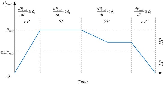
Figure 3.
Diagrammatic sketch of the vehicle’s power and response interval division.
The MPC method is employed during the HP-SP and LP-SP phases, following the SM method for the HP-FP and LP-FP phases. The state machine allocation method differs for HP and LP loads, as detailed in Section 3.2. In the FP phase, significant fluctuations are observed in the power outputs of the fuel cell and the lithium-ion battery. As a result, the SM method is employed to ensure the stabilization of the fuel cell temperature.
In the HP phase, the proposed SM for power allocation is designed to focus on the output power of the fuel cell, whereas in contrast, the SM is intended to prioritize the power of the lithium-ion battery conversely.
In a typical vehicle driving cycle, the power demand curve can be categorized into four intervals: LP-SP, LP-FP, HP-SP, and HP-FP. During the LP-SP phase, the vehicle operates at low power with relatively stable output, which corresponds to the low-speed cruising stage. The LP-FP phase is characterized by low power with rapid changes, typically occurring during the initial startup phase or low-speed emergency braking. In the HP-SP phase, the vehicle operates in a high-speed cruising stage. Finally, the HP-FP phase corresponds to the completion of the vehicle startup or high-speed emergency braking scenarios.
3.1. Model Predictive Control
MPC is an advanced control method that utilizes process models to predict the future dynamic behavior of controlled systems and solves constrained control optimization problems through rolling solutions. Due to its reliability, robustness, and practicality, MPC is widely used in complex industrial processes [38].
Generally, the state equation and relationship between input and output variables can be expressed as Equation (30):
where A and B stand for the state space matrix and input matrix, and C and D are the output matrix and direct transfer matrix, respectively.
where Q and R are the weighting matrices, f (·) and g (·) stand for the mapping relationship of x, u, y, and are the lower and upper boundaries of state variants, and are the lower and upper boundaries of input variants, and and are the lower and upper boundaries of output variants, respectively.
In this study, SOC is used as the state references with the input being the vehicle’s required power and the output being the fuel cell power. SOC reference is set to 0.5. In order to maintain SOC stability, the Voc,ba can be considered constant when the SOC fluctuates within a small range.
where is the time interval (1 s), and refer to the deviation between the SOC at time k and k + 1 and the reference value, is the SOC reference, and represents the SOC value at time k + 1, based on the state at time k.
where and stand for the weight factor of SOC deviation and PFC respectively, and is the floating range of PFC related to Pload.
The battery management system of the lithium-ion battery limits the SOC to remain between 0.2 and 0.85.
3.2. State Machine
This study proposes two finite-state machine methods for optimizing vehicle power allocation in the HP and LP stages. In the HP-FP stage, the state machine method mainly focuses on the power of fuel cells while using the less energy storage of lithium-ion batteries, known as SM1. Compared to the LP-FP stage, the power change of fuel cells is slow, and the required power is relatively low. Therefore, it is crucial for lithium-ion batteries to absorb excess energy, and the state machine method used at this stage is called SM2. The SM1 method is shown in Table 2. Compared with the SM1 method, the SM2 method only increases the rated power of the fuel cell stack by 5 kW.

Table 2.
The Power allocation of the proposed SM method for vehicles.
3.3. SM-MPC-EMS
3.3.1. Power Load of the Vehicle
Two driving cycle test suites, including the New European Driving Cycle (NEDC) and the Highway Fuel Economy Test (HWFET), are used to verify the effectiveness of the proposed EMS. The NEDC has a duration of 1180 s. In the first ten minutes, the vehicle experiences frequent start-stop operations, simulating driving conditions in suburban areas. In the subsequent phase, the vehicle enters a high-power demand stage. The HWFET is a driving cycle used primarily in the United States to evaluate the highway fuel economy of vehicles. For this study, their power load curve is shown in Figure 4. The two vehicle driving tests are solely theoretical tests for evaluating the vehicle in this study.
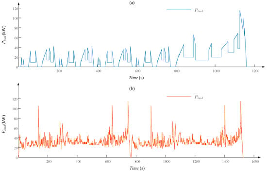
Figure 4.
Power load curve for the fuel cell vehicle in this study, (a) NEDC, and (b) HWFET.
3.3.2. Framework of SM-MPC-EMS
This section proposes an energy management method that combines SM and MPC, as shown in Figure 5. Firstly, the power demand stage of the vehicle—whether it is in the high-demand stage or the low-demand stage—is determined based on the required power and the initial SOC state of the lithium-ion battery. Then, we determine the response conditions based on the electricity demand. The SM method is used when the power gradient changes significantly, while the MPC method is used when the power change is slower. For times with high power demand, use the SM1 method; otherwise, use the SM2 method.
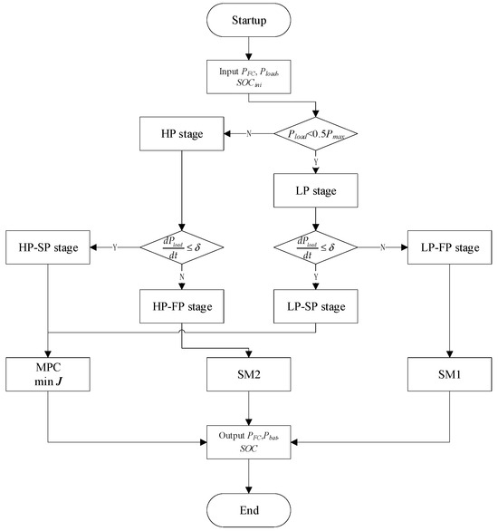
Figure 5.
The flowchart of the SM-MPC-based EMS.
4. Simulation and Evaluation
This experiment was conducted on the Dymola 2023X platform, with all modules and programs compiled within it. The experimental results are divided into three parts: (1) a description of the output characteristics of the fuel cell and lithium-ion battery; (2) the experiment is based on two internationally recognized driving cycles, NEDC and HWFET. While the vehicle’s original load is within a 1.5 kW range, specific parameters have been adjusted in this experiment, making the study highly targeted. The results will be presented in terms of hybrid system allocation outcomes, hydrogen consumption, and fluctuations in the SOC of the lithium-ion battery; (3) a temperature control experiment for the fuel cell was conducted, utilizing a PID controller to regulate the speed of the circulating cooling water pump, achieving closed-loop temperature control and maintaining the stability of the battery stack temperature.
4.1. Test-Bed
The specifications of the PEMFC stack and lithium-ion battery used in this study are shown in Table 3 below:

Table 3.
Parameter configuration of the proposed hybrid power system.
Additionally, the comparative methods used in this study are SM and MPC. SM represents the combination of SM1 and SM2 methods, focusing solely on power levels while ignoring the rate of power change.
4.2. Testing Subsystems
This section provides an independent analysis of the output characteristics of PEMFCs and lithium batteries. The loading current for the fuel cell ranges from 10 to 400 A, while the loading current for the lithium battery ranges from 10 to 300 A. The lithium-ion (Li-ion) battery has a discharge rate of 25 C.
The voltage and power outputs of both types of batteries are shown in Figure 6. Specifically, to protect the proton exchange membrane of the fuel cell, the maximum loading current is set to 400 A. The output voltages and power of both systems also meet the expected conditions.
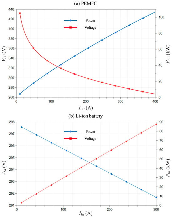
Figure 6.
Output voltage and power curves of PEMFC and lithium-ion battery at the different loading current: (a) PEMFC, and (b) lithium-ion battery.
4.3. Results of Power Allocation for SM-MPC
In this subsection, three methods, SM-MPC, SM, and MPC will be compared to verify the effectiveness of the vehicle’s power distribution.
4.3.1. SM-MPC Power Allocation Comparisons with MPC and SM Methods
From Figure 7 and Figure 8, it can be observed that for the SM method, the fixed fuel cell power leads to excessive hydrogen consumption most of the time. Compared to the SM method, MPC performs better in tracking the vehicle’s power demand. However, the SM-MPC method outperforms the MPC method in tracking the vehicle’s power demand. This is because, during low-power response, the MPC method stabilizes the fuel cell output, while during high-power response, the SM method is used, allowing the lithium-ion battery to absorb high-frequency power fluctuations. In other words, it extends the lifespan of the fuel cell stack.
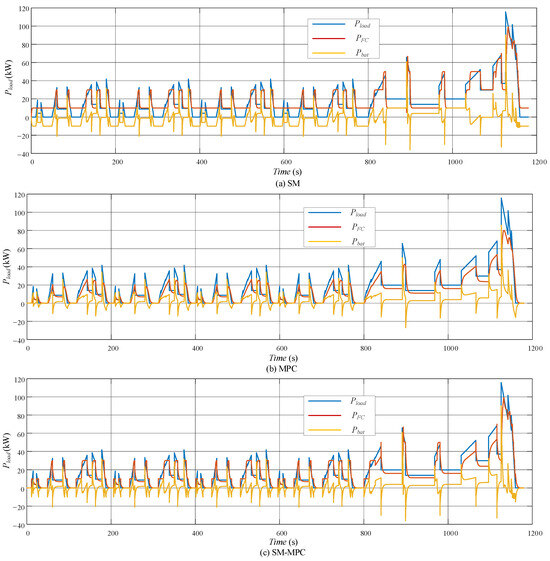
Figure 7.
Power allocation results from three methods in the NEDC: (a) SM; (b) MPC; (c) SM-MPC.
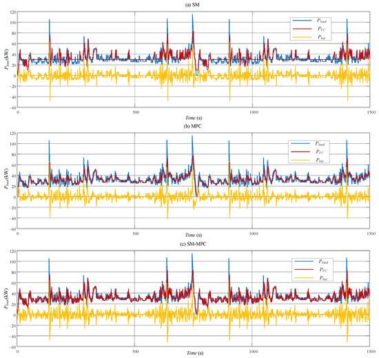
Figure 8.
Power allocation results of three methods in the HWFET: (a) SM; (b) MPC; (c) SM-MPC.
4.3.2. Fluctuation of SOC for Lithium Battery
Based on the allocation results of the three methods under the NEDC and HWFET conditions, the corresponding SOC variation curves are shown in Figure 9 and Figure 10 below. From the figures, it can be seen that under the NEDC condition, the SOC allocated by the state machine exhibits a gradually increasing trend. This is primarily because this condition spends most of its time in a low power demand phase, and the SM1 method is able to continuously charge the lithium battery, resulting in its SOC being higher than the reference point. In contrast, the MPC method shows SOC values below the reference point most of the time. However, the SM-MPC method is able to maintain the SOC near the reference value. In the HWFET driving cycle, it can still be observed that the SM-MPC method more effectively maintains the SOC value of the lithium battery.
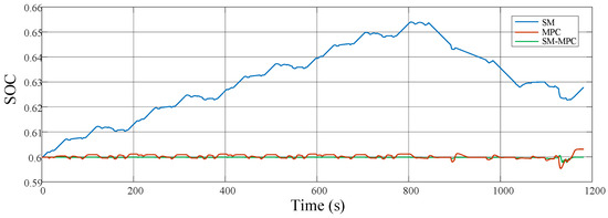
Figure 9.
SOC variation curve of three methods in the NEDC.
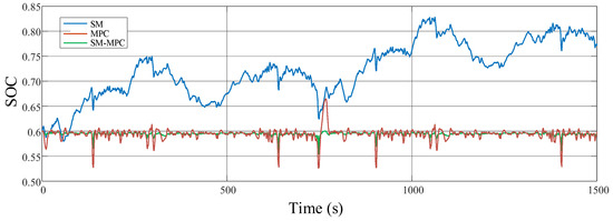
Figure 10.
SOC variation curve of three methods in the HWFET.
4.3.3. Comparison of Hydrogen Consumption
For the NEDC test, the hydrogen consumption at 1180 s varies among the three methods. The SM-MPC method has the lowest hydrogen consumption at 268.63 g, which is 7.11 g less than the MPC method and 18.22 g less than the SM method. Similarly, for the HWFET test with 1500 s, the SM-MPC method uses the least hydrogen, reducing hydrogen consumption by 1.89 g compared to the MPC method and by 10.18 g compared to the SM method, as shown in Table 4.

Table 4.
Comparison results of hydrogen consumption for three methods.
4.4. Stack Temperature Control
During the startup of the fuel cell stack, the temperature is relatively low. At this stage, circulating cooling water is still required to prevent the occurrence of local overheating in the fuel cell during actual operation, even when the average stack temperature remains low. In this study, a PID controller is used to regulate the speed of the circulating cooling water pump, thereby controlling the stack’s temperature.
In the HWFET test, the temperature variation curves of the battery stack under different cooling water flow rates, based on the battery stack power obtained using the SM-MPC method, are depicted in Figure 11. Obviously, as the cooling water flow rate increases, the overall temperature curve of the battery stack shifts downward. To ensure that the battery stack operates within an appropriate range, the cooling water flow rate is limited to below 0.5 kg/s here, in order to reduce water pump power consumption while maintaining the battery stack temperature.
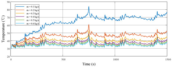
Figure 11.
Temperature variations of the battery stack under different cooling water flow rates during the HWFET test.
PID controller parameters are set to Kp = 100, Ki = 10, and Kd = 0.1 without tuning. The test results under the HWFET driving condition are shown in Figure 12.
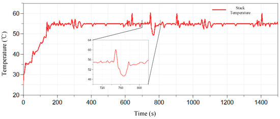
Figure 12.
Temperature variation of the fuel cell stack under the PID controller.
From the figure, it can be seen that the fuel cell stack reaches 55 °C at 170.2 s, at which point the cooling-water mass flow increases. During this period, the vehicle reaches its maximum power demand at 742.6 s, and consequently, the stack temperature subsequently rises to a maximum of 60.8 °C. The control process of the PID controller is relatively stable, with the temperature error maintained within ±5.8 °C.
The power and speed of the circulating water pump are shown in Figure 13. It can be observed that the pump’s speed fluctuates rather rapidly for most of the time. The speed easily reaches the preset upper limit and may drop abruptly to zero. Consequently, although the fuel cell stack temperature remains stable in this experiment, the temperature range being maintained is excessively large. This leads to frequent start-stop operations of the water pump, indicating that further improvements in the performance of the control algorithm are still required. In addition, the power consumption of the water pump is negligible compared to the overall power generation of the hybrid system. Therefore, when modeling high-power fuel cell hybrid systems, more auxiliary components can be considered to refine the system modeling process.
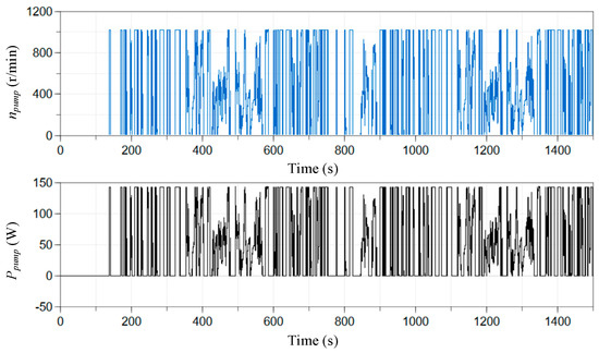
Figure 13.
Rotation speed and power consumption variations of the fuel cell stack under the PID controller.
5. Conclusions
This study presents a comprehensive investigation into a PEMFC-based hybrid power system designed for a 100 kW vehicle, focusing on energy management strategies and temperature control. By integrating the state machine (SM) and model predictive control (MPC) methods, a novel SM-MPC energy management strategy (EMS) is proposed, achieving notable improvements in system performance compared to conventional methods.
The simulation results demonstrate the effectiveness of the SM-MPC method in optimizing power allocation between the PEMFC and lithium-ion battery. In both NEDC and HWFET driving cycles, the SM-MPC method maintains the battery SOC near the reference value and achieves lower hydrogen consumption compared to the SM and MPC methods. For instance, in the NEDC cycle, the SM-MPC method reduces hydrogen consumption by 7.11 g compared to the MPC method and by 18.22 g compared to the SM method. This underscores the potential of the proposed method in enhancing the energy efficiency of hybrid power systems while ensuring the stability of system operations. Additionally, this study incorporates a PID controller for stack temperature management. The results reveal that the controller effectively regulates the stack temperature within ±5.8 °C of the target value during dynamic driving conditions.
In conclusion, the integration of SM and MPC methods provides a promising solution for addressing the nonlinear and dynamic challenges of hybrid power systems. The proposed SM-MPC EMS not only improves energy utilization but also enhances the operational stability of the PEMFC and lithium-ion battery. However, this study simplified the mathematical models of PEMFC and lithium batteries, and in the future, the nonlinear characteristics of parameters in the models can be considered to improve their accuracy. Furthermore, future work will also focus on refining the control algorithms, exploring real-time adaptability under complex driving conditions, and incorporating additional components to achieve more precise system modeling and control.
Author Contributions
Conceptualization, K.Z. and X.S.; methodology, J.J.; software, J.J.; validation, X.S.; formal analysis, X.S. and J.D.; investigation, J.J.; resources, J.J.; data curation, J.J.; writing—original draft preparation, J.J.; writing—review and editing, J.J.; visualization, J.J.; supervision, K.Z. and J.D.; project administration, K.Z.; funding acquisition, J.D. All authors have read and agreed to the published version of the manuscript.
Funding
This research was funded by the technology project about the development and application of hydrogen–lithium hybrid zero-carbon power generation system equipment for long-term emergency supply, grant number JC2024115.
Data Availability Statement
Data will be made available on request.
Acknowledgments
Sincere thanks to Changzhou Changgong Electric Power Design Institute Co., Ltd. for their financial support of the scientific research projec.
Conflicts of Interest
Author Keshu Zhang, Jiandong Jia, Xiaodan Shangguan and Jing Dong were employed by the company Changzhou Changgong Electric Power Design Institute Co., Ltd. The remaining authors declare that the research was conducted in the absence of any commercial or financial relationships that could be construed as a potential conflict of interest.
References
- Alaswad, A.; Omran, A.; Sodre, J.R.; Wilberforce, T.; Pignatelli, G.; Dassisti, M.; Olabi, A.G. Technical and commercial challenges of proton-exchange membrane (PEM) fuel cells. Energies 2020, 14, 144. [Google Scholar] [CrossRef]
- Bizon, N. Load-following mode control of a standalone renewable/fuel cell hybrid power source. Energy Convers. Manag. 2014, 77, 763–772. [Google Scholar] [CrossRef]
- Das, H.S.; Tan, C.W.; Yatim, A.H.M. Fuel cell hybrid electric vehicles: A review on power conditioning units and topologies. Renew. Sustain. Energy Rev. 2017, 76, 268–291. [Google Scholar] [CrossRef]
- Neffati, A.; Guemri, M.; Caux, S.; Fadel, M. Energy management strategies for multi source systems. Electr. Power Syst. Res. 2013, 102, 42–49. [Google Scholar] [CrossRef]
- Olatomiwa, L.; Mekhilef, S.; Ismail, M.S.; Moghavvemi, M. Energy management strategies in hybrid renewable energy systems: A review. Renew. Sustain. Energy Rev. 2016, 62, 821–835. [Google Scholar] [CrossRef]
- Lü, X.; Wu, Y.; Lian, J.; Zhang, Y.; Chen, C.; Wang, P.; Meng, L. Energy management of hybrid electric vehicles: A review of energy optimization of fuel cell hybrid power system based on genetic algorithm. Energy Convers. Manag. 2020, 205, 112474. [Google Scholar] [CrossRef]
- Vuddanti, S.; Salkuti, S.R. Review of energy management system approaches in microgrids. Energies 2021, 14, 5459. [Google Scholar] [CrossRef]
- Yin, H.; Zhou, W.; Li, M.; Ma, C.; Zhao, C. An adaptive fuzzy logic-based energy management strategy on battery/ultracapacitor hybrid electric vehicles. IEEE Trans. Transp. Electrif. 2016, 2, 300–311. [Google Scholar] [CrossRef]
- Hannan, M.A.; Wali, S.B.; Ker, P.J.; Abd Rahman, M.S.; Mansor, M.; Ramachandaramurthy, V.K.; Dong, Z.Y. Battery energy-storage system: A review of technologies, optimization objectives, constraints, approaches, and outstanding issues. J. Energy Storage 2021, 42, 103023. [Google Scholar] [CrossRef]
- Liu, X.; Ma, J.; Zhao, X.; Zhang, Y.; Zhang, K.; He, Y. Integrated component optimization and energy management for plug-in hybrid electric buses. Processes 2019, 7, 477. [Google Scholar] [CrossRef]
- Serrao, L.; Onori, S.; Rizzoni, G. ECMS as a realization of Pontryagin’s minimum principle for HEV control. In Proceedings of the 2009 American Control Conference 2009, St. Louis, MO, USA, 10–12 June 2009; pp. 3964–3969. [Google Scholar]
- Leonori, S.; Paschero, M.; Mascioli, F.M.F.; Rizzi, A. Optimization strategies for Microgrid energy management systems by Genetic Algorithms. Appl. Soft Comput. 2020, 86, 105903. [Google Scholar] [CrossRef]
- Mandal, S.; Mandal, K.K. Optimal energy management of microgrids under environmental constraints using chaos enhanced differential evolution. Renew. Energy Focus 2020, 34, 129–141. [Google Scholar] [CrossRef]
- Chen, Z.; Liu, Y.; Ye, M.; Zhang, Y.; Li, G. A survey on key techniques and development perspectives of equivalent consumption minimisation strategy for hybrid electric vehicles. Renew. Sustain. Energy Rev. 2021, 151, 111607. [Google Scholar] [CrossRef]
- Basantes, J.A.; Paredes, D.E.; Llanos, J.R.; Ortiz, D.E.; Burgos, C.D. Energy management system (EMS) based on model predictive control (MPC) for an isolated DC microgrid. Energies 2023, 16, 2912. [Google Scholar] [CrossRef]
- Li, S.; Chu, L.; Hu, J.; Pu, S.; Li, J.; Hou, Z.; Sun, W. A novel A-ECMS energy management strategy based on dragonfly algorithm for plug-in FCEVs. Sensors 2023, 23, 1192. [Google Scholar] [CrossRef] [PubMed]
- Touil, W.; Li, Z.; Outbib, R.; Hissel, D.; Jemei, S. Model predictive control energy management strategy of fuel cell hybrid electric vehicle. In Proceedings of the IECON 2022–48th Annual Conference of the IEEE Industrial Electronics Society 2022, Brussels, Belgium, 17–20 October 2022; pp. 1–8. [Google Scholar]
- Jia, C.; Qiao, W.; Cui, J.; Qu, L. Adaptive model-predictive-control-based real-time energy management of fuel cell hybrid electric vehicles. IEEE Trans. Power Electron. 2022, 38, 2681–2694. [Google Scholar] [CrossRef]
- Bavarian, M.; Soroush, M.; Kevrekidis, I.G.; Benziger, J.B. Mathematical modeling, steady-state and dynamic behavior, and control of fuel cells: A review. Ind. Eng. Chem. Res. 2010, 49, 7922–7950. [Google Scholar] [CrossRef]
- Anderson, R.; Zhang, L.; Ding, Y.; Blanco, M.; Bi, X.; Wilkinson, D.P. A critical review of two-phase flow in gas flow channels of proton exchange membrane fuel cells. J. Power Sources 2010, 195, 4531–4553. [Google Scholar] [CrossRef]
- Rashidi, S.; Karimi, N.; Sunden, B.; Kim, K.C.; Olabi, A.G.; Mahian, O. Progress and challenges on the thermal management of electrochemical energy conversion and storage technologies: Fuel cells, electrolysers, and supercapacitors. Prog. Energy Combust. Sci. 2022, 88, 100966. [Google Scholar] [CrossRef]
- Miller, M.; Bazylak, A. A review of polymer electrolyte membrane fuel cell stack testing. J. Power Sources 2011, 196, 601–613. [Google Scholar] [CrossRef]
- Sharma, P.; Cirrincione, M.; Mohammadi, A.; Cirrincione, G.; Kumar, R.R. An overview of artificial intelligence-based techniques for PEMFC system diagnosis. IEEE Access 2024, 12, 165708–165735. [Google Scholar] [CrossRef]
- Chavan, S.L.; Talange, D.B. Modeling and performance evaluation of PEM fuel cell by controlling its input parameters. Energy 2017, 138, 437–445. [Google Scholar] [CrossRef]
- Kucernak, A.R.; Zalitis, C. General models for the electrochemical hydrogen oxidation and hydrogen evolution reactions: Theoretical derivation and experimental results under near mass-transport free conditions. J. Phys. Chem. C 2016, 120, 10721–10745. [Google Scholar] [CrossRef]
- Virkar, A.V.; Chen, J.; Tanner, C.W.; Kim, J.W. The role of electrode microstructure on activation and concentration polarizations in solid oxide fuel cells. Solid State Ion. 2000, 131, 189–198. [Google Scholar] [CrossRef]
- Asghari, S.; Mokmeli, A.; Samavati, M. Study of PEM fuel cell performance by electrochemical impedance spectroscopy. Int. J. Hydrogen Energy 2010, 35, 9283–9290. [Google Scholar] [CrossRef]
- Santarelli, M.G.; Torchio, M.F.; Cochis, P. Parameters estimation of a PEM fuel cell polarization curve and analysis of their behavior with temperature. J. Power Sources 2006, 159, 824–835. [Google Scholar] [CrossRef]
- Song, C.; Tang, Y.; Zhang, J.L.; Zhang, J.; Wang, H.; Shen, J.; Kozak, P. PEM fuel cell reaction kinetics in the temperature range of 23–120 C. Electrochim. Acta 2007, 52, 2552–2561. [Google Scholar] [CrossRef]
- Fly, A.; Thring, R.H. Temperature regulation in an evaporatively cooled proton exchange membrane fuel cell stack. Int. J. Hydrogen Energy 2015, 40, 11976–11982. [Google Scholar] [CrossRef]
- Dale, N.V.; Mann, M.D.; Salehfar, H. Semiempirical model based on thermodynamic principles for determining 6 kW proton exchange membrane electrolyzer stack characteristics. J. Power Sources 2008, 185, 1348–1353. [Google Scholar] [CrossRef]
- Yu, Y.; Chen, M.; Zaman, S.; Xing, S.; Wang, M.; Wang, H. Thermal management system for liquid-cooling PEMFC stack: From primary configuration to system control strategy. ETransportation 2022, 12, 100165. [Google Scholar] [CrossRef]
- Tippmann, S.; Walper, D.; Balboa, L.; Spier, B.; Bessler, W.G. Low-temperature charging of lithium-ion cells part I: Electrochemical modeling and experimental investigation of degradation behavior. J. Power Sources 2014, 252, 305–316. [Google Scholar] [CrossRef]
- Koad, R.B.; Zobaa, A.F.; El-Shahat, A. A novel MPPT algorithm based on particle swarm optimization for photovoltaic systems. IEEE Trans. Sustain. Energy 2016, 8, 468–476. [Google Scholar] [CrossRef]
- Solmaz, H.; Kocakulak, T. Determination of lithium ion battery characteristics for hybrid vehicle models. Int. J. Automot. Sci. Technol. 2020, 4, 264–271. [Google Scholar] [CrossRef]
- Zhao, D.; Guo, C.; Li, Y.; Pan, S.; Feng, S.; Zhu, H. Study of the temperature distribution in insulated gate bipolar transistor module under different test conditions. Microelectron. Reliab. 2023, 140, 114880. [Google Scholar] [CrossRef]
- Hou, Z.; Chu, L.; Du, W.; Hu, J.; Jiang, J.; Yang, J.; Zhang, Y. A Novel Dual-Model MPC-based Energy Management Strategy for Fuel Cell Electric Vehicle. IEEE Trans. Transp. Electrif. 2024, 10, 8585–8604. [Google Scholar] [CrossRef]
- Schwenzer, M.; Ay, M.; Bergs, T.; Abel, D. Review on model predictive control: An engineering perspective. Int. J. Adv. Manuf. Technol. 2021, 117, 1327–1349. [Google Scholar] [CrossRef]
Disclaimer/Publisher’s Note: The statements, opinions and data contained in all publications are solely those of the individual author(s) and contributor(s) and not of MDPI and/or the editor(s). MDPI and/or the editor(s) disclaim responsibility for any injury to people or property resulting from any ideas, methods, instructions or products referred to in the content. |
© 2025 by the authors. Licensee MDPI, Basel, Switzerland. This article is an open access article distributed under the terms and conditions of the Creative Commons Attribution (CC BY) license (https://creativecommons.org/licenses/by/4.0/).