Article

An Intelligent Control Method for Servo Motor Based on Reinforcement Learning

1
School of Computer and Information Engineering, Nantong Institute of Technology, Nantong 226001, China
2
School of Software, Northwestern Polytechnical University, Xi’an 710000, China
*
Author to whom correspondence should be addressed.
Algorithms 2024, 17(1), 14; https://doi.org/10.3390/a17010014
Submission received: 23 November 2023 / Revised: 22 December 2023 / Accepted: 25 December 2023 / Published: 28 December 2023
(This article belongs to the Special Issue Advancements in Reinforcement Learning Algorithms)

Abstract

:
Servo motors play an important role in automation equipment and have been used in several manufacturing fields. However, the commonly used control methods need their parameters to be set manually, which is rather difficult, and this means that these methods generally cannot adapt to changes in operation conditions. Therefore, in this study, we propose an intelligent control method for a servo motor based on reinforcement learning and that can train an agent to produce a duty cycle according to the servo error between the current state and the target speed or torque. The proposed method can adjust its control strategy online to reduce the servo error caused by a change in operation conditions. We verify its performance on three different servo motors and control tasks. The experimental results show that the proposed method can achieve smaller servo errors than others in most cases.

1. Introduction

A servo motor plays an important role in the composition of automation equipment. It can convert the voltage signal into torque and speed to drive the controlled object with high control precision. Because servo motors can meet the torque and speed control requirements of most tasks, they have been widely used in many manufacturing fields, such as in aerospace, automotive manufacturing, and robotics, among others [1].
In the servo motor control system, the most widely used and stable control method is proportion–integration–differentiation (PID), which can generate the control strategy only by the tracking error. This control strategy bears the advantage of a control mechanism which is completely independent of the mathematical model of the controlled object [2]. However, the PID parameters can generally only be set manually. Thus, the actual control effect not only depends on the debugging experience of engineering personnel, but also requires another time-consuming process to verify the control effect of parameters. Moreover, during the operation of the servo system, the change in magnetic saturation degree, temperature, load and other conditions of the motor will degrade the performance of the PID controller designed with the original parameters. Therefore, the PID controller parameters should be adjusted in a timely manner according to the actual working conditions, which will increase the difficulty of manual parameter setting. In order to reduce the burden of manual parameter setting and improve the control effect, the servo system needs an adaptive control algorithm which is able to effectively solve the problems caused by the changes in servo motor working conditions by identifying some related parameter values online and modifying the control strategy in real time [3,4,5,6,7].
In recent years, reinforcement learning, as a major branch of artificial intelligence, has gained increased attention and made breakthroughs in fields such as autonomous driving [8,9], path planning [10,11], and robotics [12,13]. Reinforcement learning imitates humans’ self-learning ability and can continuously optimize decision-making strategies through a trial and error mechanism to realize its own evolution [14]. By applying the reinforcement learning algorithm, it may prompt the servo motor control system to adapt to the complex control environment by automatically adjusting the output of the control system through the imitation of human decision-making behavior [15,16,17,18]. The existing methods are all based on deterministic strategies, and their learned optimal strategies are uniquely determined action values which lack the ability to explore the interaction environment. To explore other actions around the current optimal action, noise needs to be artificially added to the policy. The performance is affected. Moreover, in the existing algorithm, the tracking error is taken as the basis of reward, and the error values in a period of time are uniformly input to the neural network model. Then, the coefficients of proportion, integral, and differential of the PID algorithm are learned via the neural network. This method only allows the agent to control the motor by tracking errors, although it improves the generalization performance of the algorithm to a certain extent, but also causes the loss of the motor running-state information, which is not conducive to further improving the control accuracy.
In view of the problems faced by traditional industrial control systems, this study intends to design a deep reinforcement learning controller based on reference trajectory coding to implement intelligent servo motor control. In this, the running state of the servo motor and the target trajectory in the control process are regarded as two different items of input information, so that the agent can make better use of the external information to make control decisions. Therefore, the control precision of the reinforcement learning motor control algorithm is more optimized. This investigation will break through the limitation of manually setting controller parameters, realize the online real-time setting of a servo motor control strategy, and maximize the performance of the servo motor while reducing the manpower burden. The study has broad application prospects in aerospace, industrial robots, and other fields.

2. Basic Knowledge

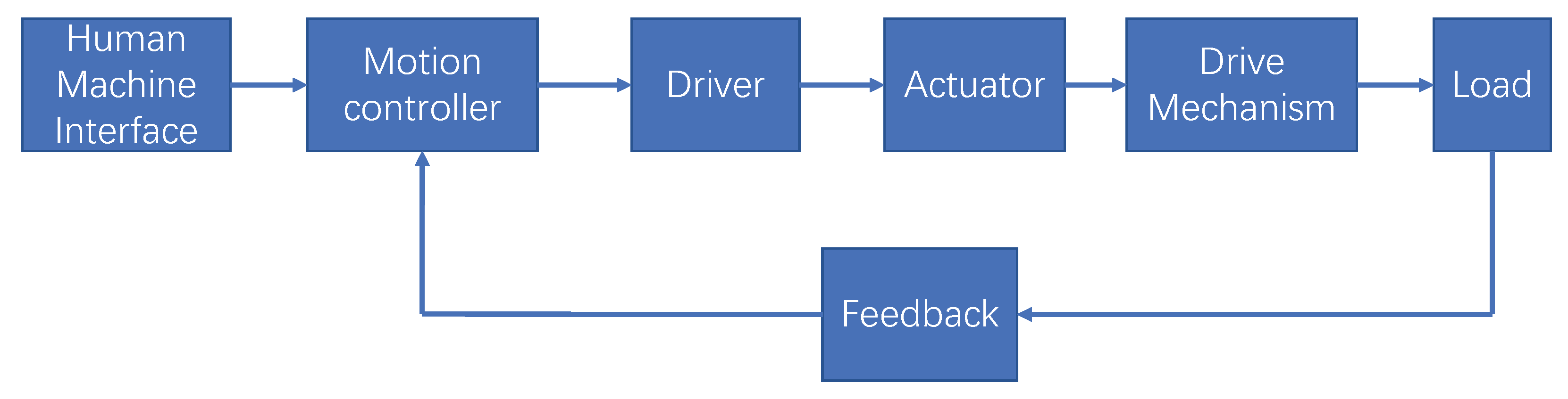
2.1. Motion Control System

As shown in Figure 1, a complete servo motor control system includes seven main parts, namely, the man–machine interface, motion controller, driver, actuator, drive mechanism, load, and a feedback part.
The motor control method works in the motion controller. As a control center, the motion controller closes the feedback loop by monitoring the input and output of the system. The controller receives feedback from the motor and calculates the servo error between the actual and given state. Then, the motor control method generates a control signal to adjust the state of the motor and reduce the error. After that, the driver amplifies these signals to a high-power voltage and current to meet the needs of the motor operation [2].
Our work mainly focuses on the motor control method, and the goal is to adjust it online to adapt it to changes in operating conditions.

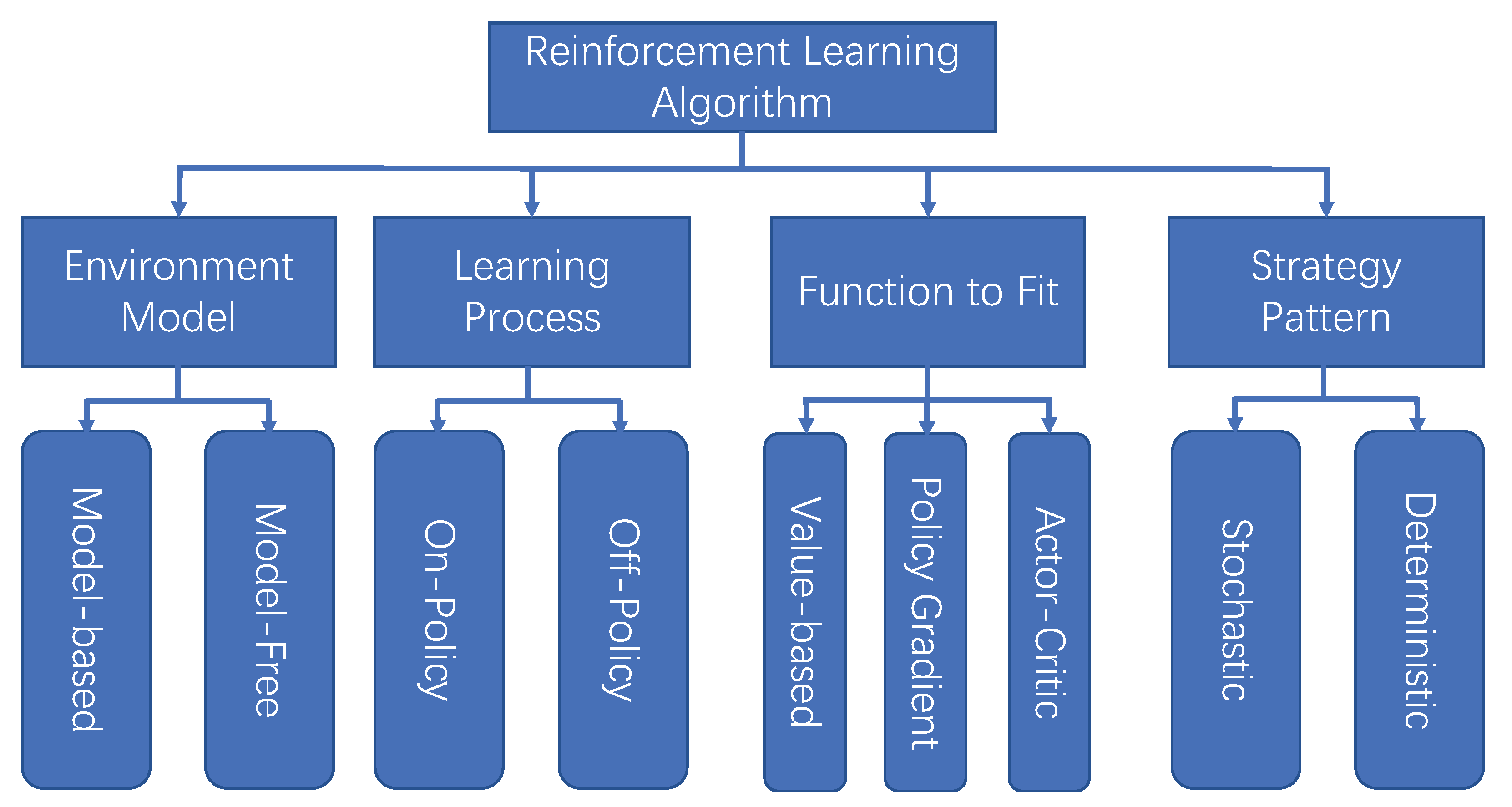
2.2. Reinforcement Learning

Reinforcement learning is developed from the idea of trial and error learning. Its learning process does not rely on artificially marked data labels, but instead on the reward or punishment mechanism. More specifically, constant trial and error in an environment full of uncertainty are considered, and a decision-making method that can obtain the maximum reward in the environment is summarized. Reinforcement learning algorithms can be classified in various ways, as shown in Figure 2.

2.2.1. On-Policy Algorithm and Off-Policy Algorithm

The policies used by the reinforcement learning algorithm can be divided into two kinds: one is used to interact with environment in the learning process and the other is used by the final learned algorithm. According to the relationship between the two policies, the reinforcement learning algorithm can be divided into an on-policy algorithm and an off-policy algorithm [19].
The on-policy algorithm means that the policies used by the agent to interact with the environment are the same as those eventually learned. During the learning process, only the samples of environment interaction that are collected using their own strategies can be used [20].
An off-policy algorithm refers to the agent using one policy when interacting with the environment, and then obtaining a different policy after learning. Compared with the on-policy algorithm, the off-policy algorithm can be used to explore the environment when collecting interactive data within the environment. Thus, it can improve the utilization efficiency of data and will not affect the performance of the final policy [21,22].

2.2.2. Model-Free Algorithm and Model-Based Algorithm

In the learning process, the model-free reinforcement learning agent only learns the value function and policy function of the current environment without direct environment cognition.
A model-based reinforcement learning agent builds a virtual model of the real environment in the process of interacting with the environment, and it replaces the real environment with a small amount of the virtual environment to reduce interaction requirements. Although model-based algorithms can improve the learning speed by reducing the number of interactions between the agent and the environment, the performances of these algorithms are often inferior to those of model-free algorithms due to their low modeling accuracy [23].

2.2.3. Value Function Algorithm and Policy Gradient Algorithm

According to the different learning contents and agent methods, reinforcement learning algorithms can be divided into the value function method, policy gradient method, and actor–critic method [24].
The agent based on the value function method only learns the value function. In the actual use process, it will choose an action with a higher value to interact with the environment, according to the value of each action in the current state.
When using the policy gradient method, the agent only learns the strategy function, and the algorithm dynamically adjusts the probability value of taking the action according to the subsequent income generated by each action, and it gradually converges to the optimal strategy. After learning, the algorithm directly uses the policy function to make a decision.
The calculation efficiency of the policy gradient method is low. Therefore, the actor–critic method, combining the value function and policy gradient, was proposed. In this approach, the agent learns and optimizes both the value function and the policy function at the same time [25].

2.2.4. Stochastic Strategy and Deterministic Strategy

When the agent interacts with the environment using a stochastic strategy, it may perform any action in the action space, and the execution probability of each action is non-zero [26]. When the agent uses deterministic strategy to interact with the environment, the agent will only take the optimal action in its cognition, which can be said to be the preferred action [27].
Stochastic strategy has advantages that deterministic strategy does not have. First, in the learning process, the randomness of stochastic strategy can be directly used to explore the environment, and the agent can correct the exploration scope itself in the learning process, so that it will not easily fall into the local optimum. Second, after learning, deterministic strategies can only output the same action value for the same environment, which is easy to target in the game process with other agents [28,29].

3. Problem Description

3.1. Control Mode of Servo Motor

The general servo motor has three control modes: position control, torque control, and speed control.
The position control mode is usually assigned to the displacement directly through the external input. Because the position mode can control the speed and position strictly, it is generally applied to the positioning device.
The speed control mode is used to control the motor rotation speed through the external input, which has been quite widely applied. In addition, there is a need for a rapid response of the continuous speed control system, the upper closed-loop positioning system, and the need for a rapid change in the speed system.
Torque control mode is used to change the size of the motor’s external output torque through the external input. It is mainly used in winding and unwinding devices with strict requirements regarding the force of the material, such as a winding device or fiber-pulling equipment.
In this work, we only consider the torque control mode and speed control mode, since position control can be achieved via speed control in definite time. The speed and torque of the motor are determined by the duty cycle, which denotes the ratio of the up-level time to the whole-cycle time within a pulse period. The range of the duty cycle is [0, 1], and its value is proportional to the velocity and torque.

3.2. State Information of Servo Motor

In this paper, we only consider three commonly used servo motors: the externally excited DC motor (ExtEx), series DC motor (Series), and three-phase permanent magnet synchronous motor (PMSM). The state information of the servo motor generally refers to some physical quantities that can describe the actual running state of the motor, such as the angular velocity of the motor, the actual current, the actual voltage, and the motor torque.
The state of an externally excited DC motor can be described by its angular velocity ω , torque T, armature current i A , excitation circuit current i E , armature voltage u A , excitation circuit voltage u E , and service voltage u s e r [2], which is denoted as Equation (1).
O E x t E x = [ ω , T , i A , i E , u A , u E , u s e r ]
In the circuit construction of a series DC motor, the armature and the excitation circuit are connected in series, so their armature values are the same and can be denoted as i. The input voltage is the sum of armature voltage and excitation circuit voltage, which can be denoted as u = u A + u E [2]. The state of the series DC motor is denoted as Equation (2).
O S e r i e s = [ ω , T , i , u , u s e r ]
A permanent magnet synchronous motor consists of three phases; each of them has a phase voltage and phase current, denoted as u a , u b , u c , i a , i b , and i c , respectively. Because the dynamic mathematical model of the PMSM in a three-dimensional static coordinate system is too complex, it is often converted to a DQ two-phase rotor coordinate system, where the inductance matrix will be simplified to a constant. In DQ coordinates, the voltage components in the d and q directions are denoted as u s d and u s q , respectively. The current components in the d and q directions are denoted as i s d and i s q , respectively. The rotor flux is ε . Therefore, the state of the PMSM is denoted as Equation (3).
O P M S M = [ ω , T , i a , i b , i c , i s q , i s d , u a , u b , u c , u s q , u s d , u s e r , ε ]

3.3. Task of Agent

To enable the motor to operate at a given speed or torque, the task of the reinforcement learning agent is to output an appropriate duty cycle according to the servo error, which not only depends on the state of the motor but also depends on the target value.
In order to reduce the influence of observation errors on the control strategy and the learning process of the agent, and to capture some motor running states that cannot be represented by instantaneous observations, each model input of the algorithm not only includes the current motor running state observations, but also combines historical information within a period of time. This includes the observation of the motor running state and the control output of the agent in the past period. The state input s t of each neural network model can be specifically expressed as (4).
s t = [ o t h , a t h , o t h + 1 , a t h + 1 , . . . , o t ]
where o t represents all operational state observations of the motor at time t, i.e., Equations (1)–(3); a t represents the action output by the agent at time t; and h indicates the length of the history information contained in the status input.
The action output of the reinforcement learning agent is the duty cycle. For the externally excited DC motor, it includes duty cycles of the armature voltage and excitation circuit voltage, which are denoted as a E x t E x = [ a A , a E ] . For a series DC motor, it only includes one duty cycle of the input voltage and is denoted as a S e r i e s . For the permanent magnet synchronous motor, it includes three duty cycles of the A, B, and C phases, respectively, which is denoted as a P M S M = [ a A , a B , a C ] . Each output action is a real number between 0 and 1, and as the value increases from 0 to 1, the duty cycle gradually increases.
Therefore, the task of the agent is to output the appropriate duty cycle a t at time t based on the state input s t in order to control the motor running under the set target g t . g denotes the value of the set speed or torque.

The Interaction between Agent and Environment

Given a task space G including all possible speeds or torques, the reward function of the model is expressed as r ( s , a , g ) , which calculates the real reward according to the environment state s, the duty cycle a output by the agent, and the target g. The reward is given to the agent by the environment after the agent outputs the duty cycle in a specific state under this target. At the beginning of each turn, the environment obtains an initial state of the environment s 0 and the target g 0 . In each subsequent turn, the agent makes decisions according to the environment state s t and the target g t to be tracked in the current time step t. When the agent output duty cycle occurs, the environment feeds back a reward signal r t = r ( s t , a t , g t ) to the agent. At the same time, the environment transitions to the next state s t + 1 , and gives a new target g t + 1 . The reward function is calculated based on the negative of the value of the current servo error.

4. The Proposed Intelligent Control Method

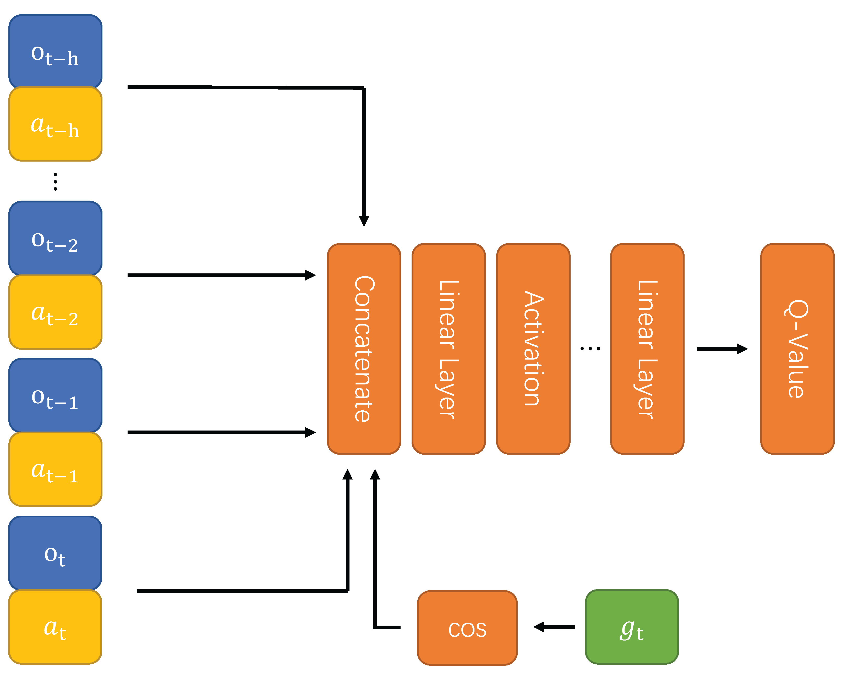
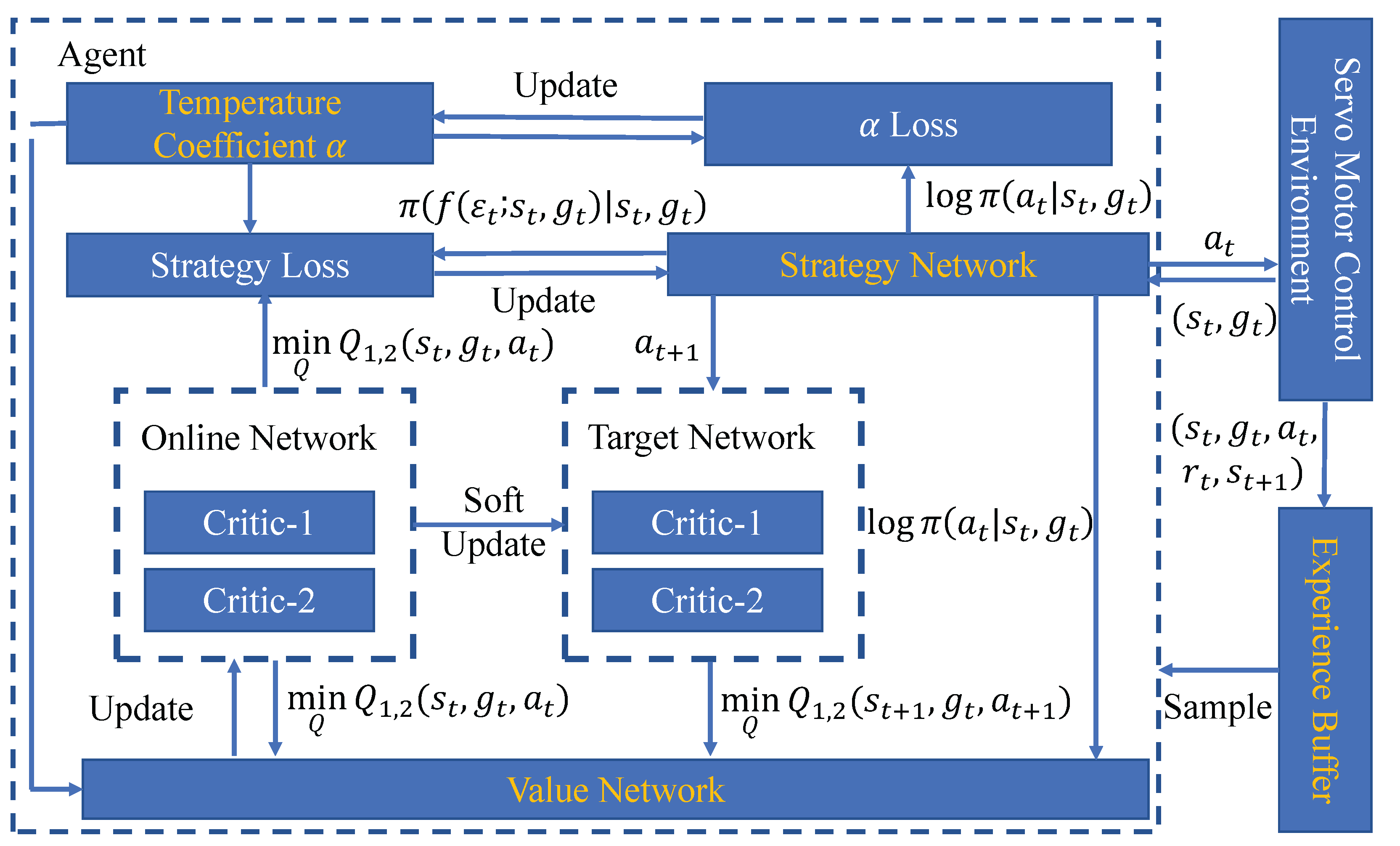
4.1. The Structure of the Control Method

As shown in Figure 3, reinforcement learning based on the intelligent control method consists of four main components: (1) strategy network, which is used to control the running state of the motor and output the specific duty cycle; (2) value network, which is used to evaluate the output value of each duty ratio of the policy network under a specific state and target trajectory; (3) temperature coefficient, which is used to balance the proportional relationship between the duty ratio value and the strategy in the loss function, affecting the degree of emphasis on the exploration and utilization of the algorithm; (4) experience buffer, which is used to store interactive data between the reinforcement learning agent and servo motor control environment as training data for strategy improvement.

4.1.1. Structure and Loss Function of Value Network

As shown in Figure 4, the inputs of the value network are the motor running state s t , target speed or torque g t , and the duty ratio output of the agent a t . Its output is Q ( s t , g t , a t ) , denoting the reward of the duty cycle in a given state.
To solve the overvaluation problem of the duty ratio, the algorithm uses two value networks with identical structures. When estimating the duty cycle value, the output values of the two networks are compared, and the minimum value is taken as the final output. In the training process, the objective function of value network J ( θ ) can be expressed as Equation (5).
J ( θ ) = E ( s t , g t , a t ) D , a t + 1 π 1 2 Q ( s t , g t , a t ) r ( s t , g t , a t ) γ Q * ( s t + 1 , g t , a t + 1 ) α l o g π ( a t + 1 | s t + 1 , g t ) 2
where D represents the experience buffer that stores the interactive data with the environment, γ is the discount factor, α is the temperature coefficient, and π ( a t | s t , g t ) is the policy function that will be described next.
Equation (5) represents the update objective function of the value network. By sampling in the replay buffer D, the calculation method used is the negative of the absolute value of the difference between the target of the control trajectory and the actual control result.

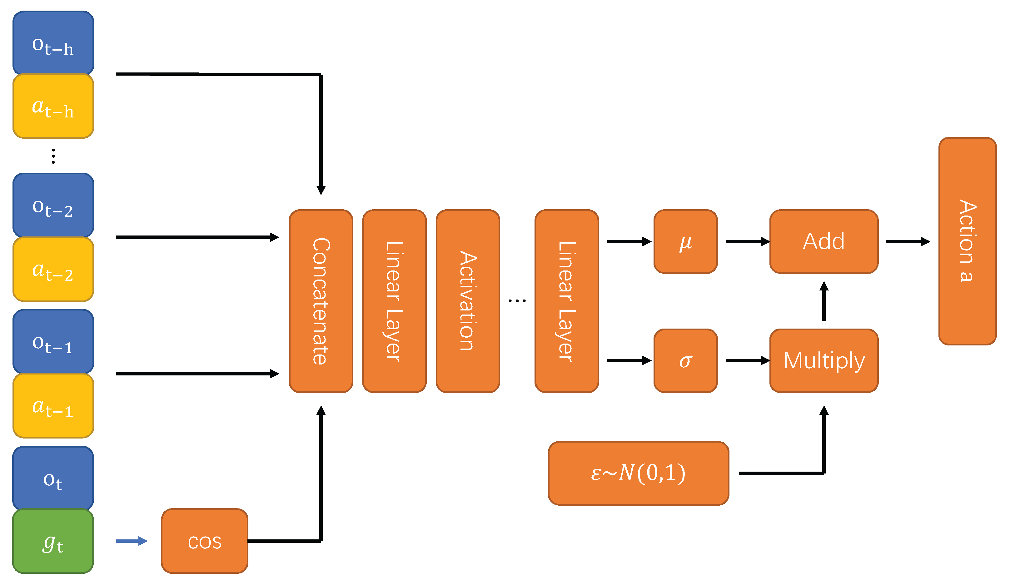
4.1.2. Structure and Loss Function of Strategy Network

As shown in Figure 5, the inputs of the strategy network are the motor state s t and target g t , and its output is the duty ratio after normalization, which is denoted as π ( s t , g t ) . Therefore, the objective function of the strategy network can be expressed as Equation (6).
J ( ϕ ) = E s t D log π f ε t ; s t , g t Q s t , f ε t ; s t , g t
where ε t is noise sampled from a standard normal distribution. Equation (6) represents the update objective function of the policy network, which adjusts the update objective of the proposed control algorithm based on the structure and input–output of the value network and policy network, while the training method remains basically the same.
In order to use the gradient descent method to train the policy network, it is necessary to make the random policy output of the network derivable. Therefore, the algorithm uses the reparameterization technique to calculate the output of the strategy network. The strategy network itself outputs two real values, μ and σ , corresponding to the mean and standard deviation of the normal distribution, respectively. The value of the output action a t can be calculated via Equation (7).
a t = f ( ε t ; s t , g t ) = ε t × σ ( s t , g t ) + μ ( s t , g t )

4.1.3. Temperature Coefficient and Its Loss Function

The temperature coefficient α controls the relative importance between the instantaneous reward and strategy entropy in each time step and affects the randomness of the optimal strategy. α is a learnable parameter, so only an initial value needs to be provided at the beginning of training, and then the value of α can be dynamically adjusted during the course of the algorithm. It can be adjusted using the objective function in Equation (8).
J ( α ) = E ( s t , g t ) D , a t π α log π ( a t | h t , s t , g t ) α H 0
where H 0 represents the target value of entropy, and is set to the negative of the duty cycle dimension in this paper. The temperature coefficient is updated by iteration, similar to that for the value network and the actor network. In each network-weight-updating process, the value network, the actor network, and the temperature coefficient are trained sequentially, and all the used samples are drawn from the replay buffer. When the entropy of the current strategy is lower than the target value, the objective function will increase the value of α . Otherwise, the value of α will be reduced. In this way, the relative importance of policy entropy in the objective function of the policy network is adjusted to control the direction of policy improvement.
The pseudocode of the proposed method is summarized in Algorithm 1.
Algorithm 1 The proposed intelligent control method
Require: 
Parameters of value network θ 1 and θ 2 , parameter of policy network φ , and experience pool D .
1:
for each iteration do
2:
   for each environment step do
3:
      obtain the duty cycle a t according to the state
       s t , the current target g t and the sampling strategy
       π φ ;
4:
      execute duty cycle a t and then obtain the next
      state s t + 1 , the next target g t + 1 and the reward r t ;
5:
      store sample ( s t , a t , r t , s t + 1 , g t ) into experience pool
       D ;
6:
      for each gradient step do
7:
         evenly extract a batch size sample from D for
         training;
8:
         update value network parameters θ 1 and θ 2 ;
9:
         update policy network parameter φ ;
10:
        update temperature coefficient α ;
11:
      end for
12:
   end for
13:
end for

5. Experiment and Analysis

5.1. Experimental Environment and Setting

To verify the effectiveness of the proposed reinforcement learning control algorithm, the Python-based Gym Electric Motor was selected, which is an open-source simulation platform. It provides a simple algorithm interface for reinforcement learning agents like the OpenAI Gym. Therefore, the interaction between agents and the environment can be simulated conveniently, which provides favorable conditions for researchers to develop and test reinforcement learning control algorithms [30].
As shown in Table 1, six common tasks were selected to verify the performance of our method.
Aside from the proposed method, four other similar methods are selected to compare the performance. Firstly, the depth deterministic policy gradient (DDPG) and twin delay depth deterministic strategy gradient (TD3) of two deep reinforcement learning algorithms are selected. Secondly, the difference value input (DVI) and state input without special processing (SI) are also taken into account as feature extraction methods. Therefore, we combined the reinforcement learning algorithm and feature extraction method to obtain the four comparison methods, which are termed as DDPG-DVI, DDPG-SI, TD3-DVI, and TD3-SI, respectively.
Both the strategy network and value network of each method contain two hidden layers, and each of them has 512 neurons. The ReLU activation function is used. The historical input length of the value network is 20. The chosen batch size is 256. The Adam optimizer [31] is used to optimize network parameters for gradient descent, and the learning rate of the optimizer is set to 0.00003. The discount reward factor is 0.99.

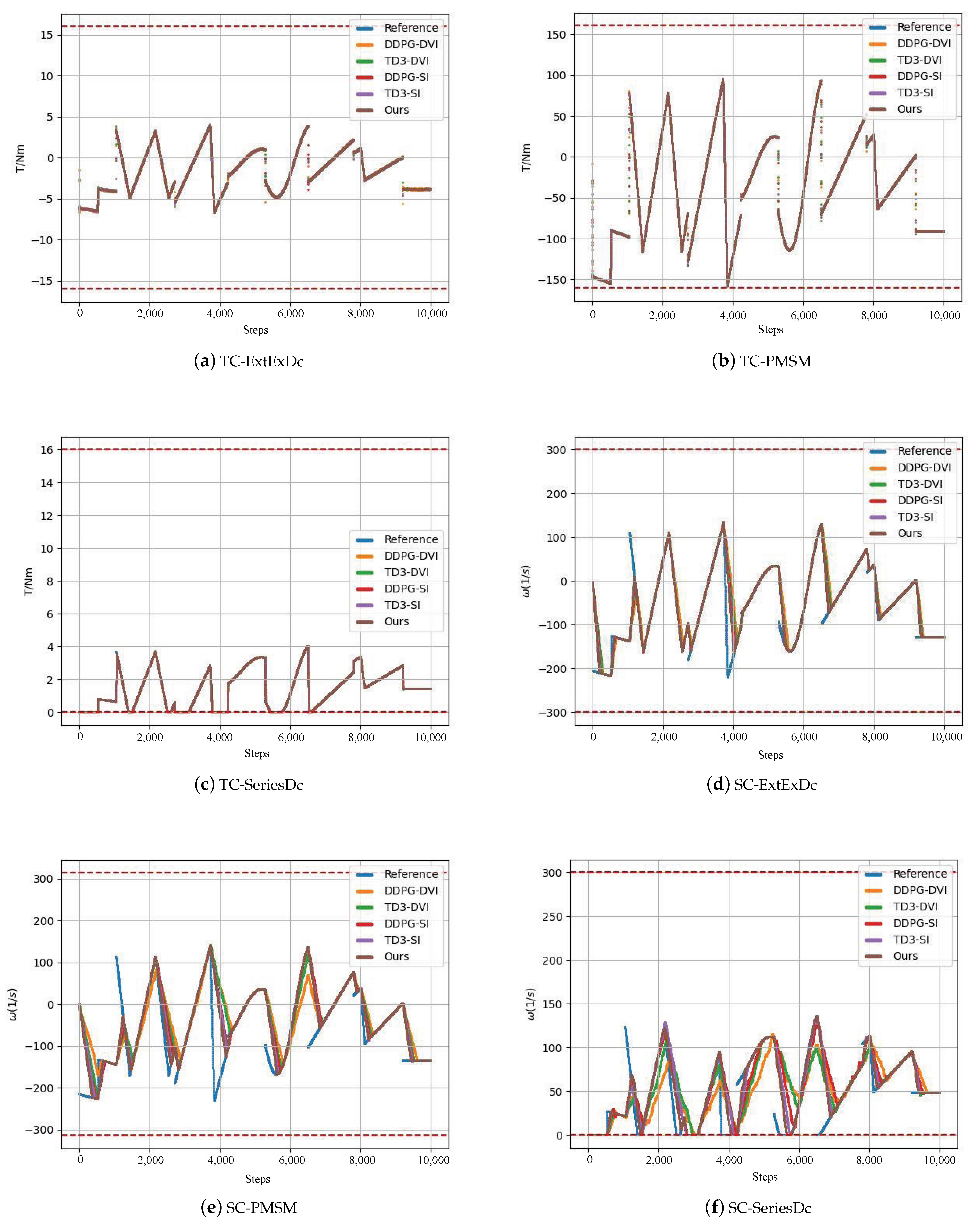
5.2. Comparison Experiment for Control Performance

In each control task, the same control target is used to compare the control performance of all comparison algorithms. The total length of each test was 10,000 time steps, and each control algorithm repeated the process under 10 identical random seeds. The mean absolute error (MAE) during the test was used as a measure of the control accuracy.
Figure 6 shows the control performance of all the control algorithms in each control task under the same target trajectory when the random seed is 0, where the horizontal coordinate represents the number of time steps in the test process, and the vertical coordinate represents the actual size of the target state quantity of the control task. By measuring the distance between the actual running state and the target trajectory of each control algorithm in the control process, we can roughly see the difference in the control effect among various algorithms. The blue lines represent the control targets, while the lines of other colors represent the actual control results of various algorithms. The smaller the gap, the stronger the ability of the algorithm to control the motor to track the reference trajectory; and the larger the gap, the weaker the ability of the algorithm to control the motor to track the target trajectory. Table 2 shows the mean and standard deviation of the mean absolute error in tests based on 10 different random seeds.
As shown in Figure 6, for the torque control, the performance difference between control methods is minimal. This may be because the response speed of the current loop is fast, and so no algorithms can easily open the gap. In the task of speed control, it can be clearly seen that the distance between the motor running trajectory controlled by the proposed algorithm and the target trajectory is the closest. Compared with other algorithms, our algorithm has certain advantages regarding control accuracy. The difference in control accuracy between algorithms may be more highly reflected in control trajectory changes due to the slow response speed of the speed control. In general, the proposed soft actor–critic algorithm based on target trajectory coding maintains the closest distance to the target trajectory. No matter how the target trajectory changes, the proposed algorithm can respond to the change quickly and adjust the running state of the motor in time.
As can be seen from Table 2, in both torque control and speed control, our algorithm obtains the smallest mean absolute error in all tasks, indicating that compared with the other algorithms, the proposed algorithm has the highest control accuracy under a regular control trajectory, although it has a higher standard deviation in individual tasks. This shows that the performance of the control algorithm may not be as stable as that of similar algorithms, but, in general, it achieves the best effect.

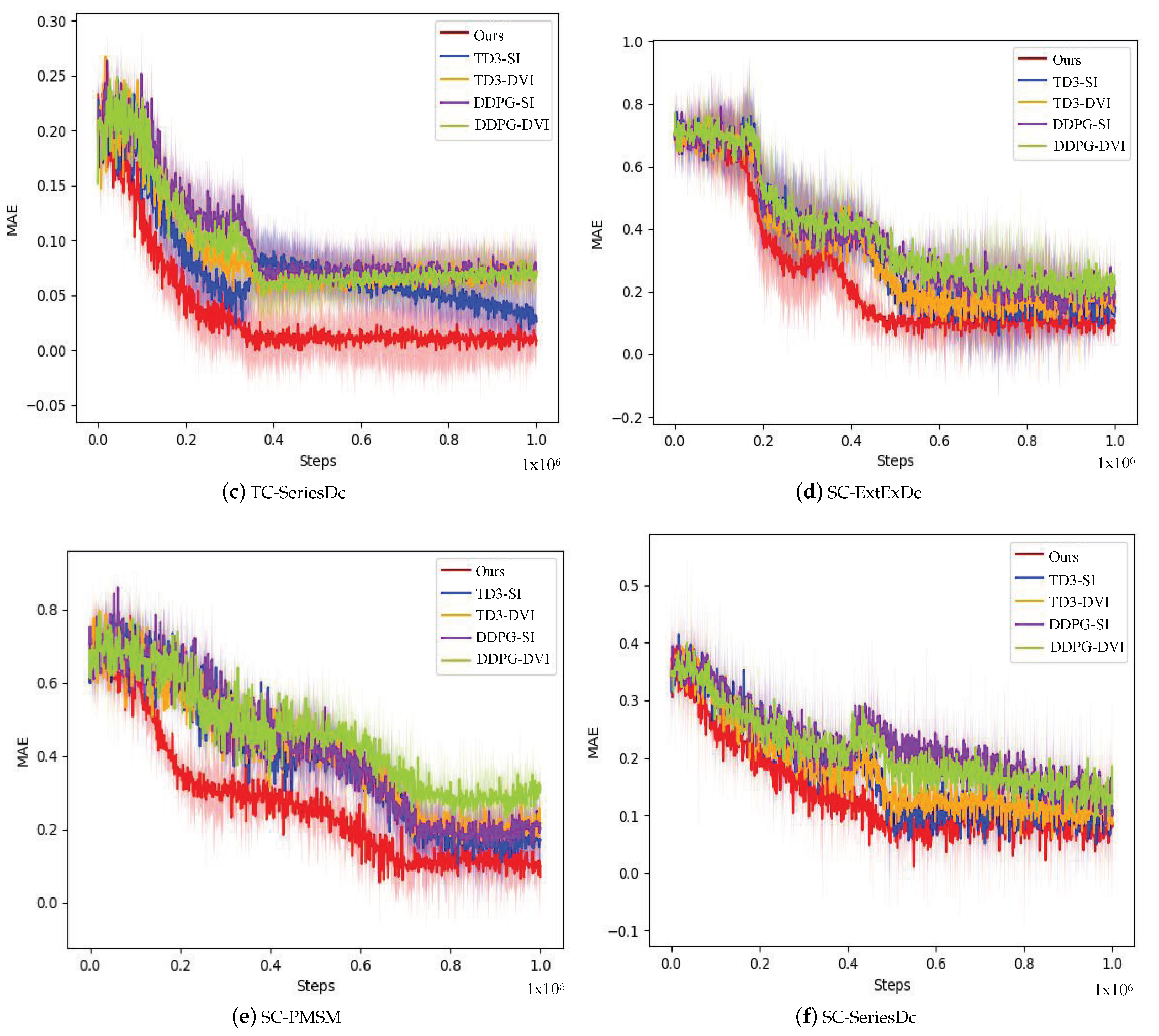
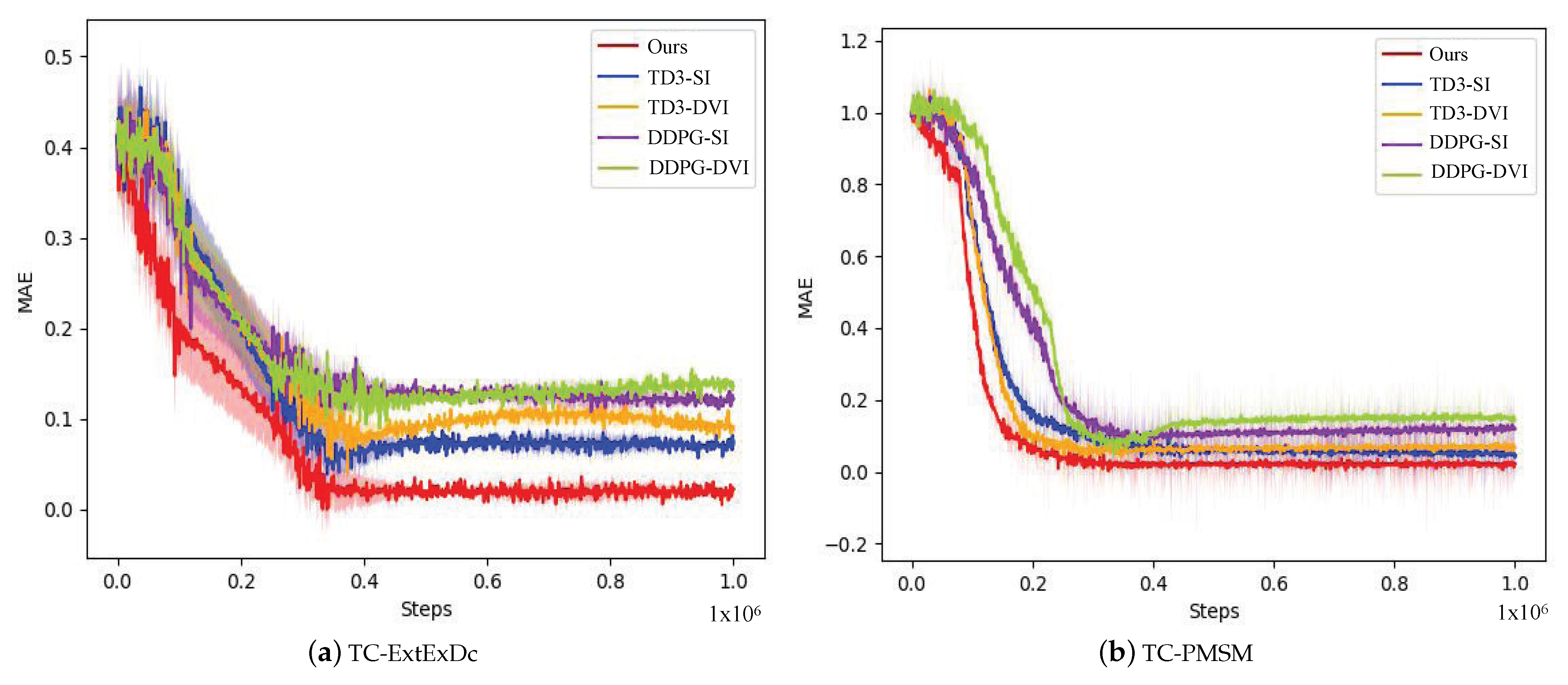
5.3. Comparison Experiment for Training Speed

The comparison experiment for training speed uses six control tasks provided by Gym Electric Motor (from Cont-TCExtExDc-v0, Cont-SC-ExtExDc-v0, Cont-TC-PMSM-v0, Cont-SC-PMSM-v0, Cont-TCSeriesDc-v0, and Cont-SC-SeriesDc-v0). The experiment records the mean absolute error between the target trajectory and the actual running state of the motor in the control task from the initialization state of the algorithm to a certain training time. The target trajectory includes the step signal, asymmetric triangle signal, and sine wave signal, and it randomly switches between the three forms. The total training time is 10 6 time steps. In the whole process of the experiment, the default random initialization parameters provided by Gym Electric Motor were used, and to ensure that the algorithm performance would not deviate too much from the actual performance during the test, we used 10 fixed random seeds to repeat the experiment.
In order for the MAE to better reflect the changing trend in the algorithm’s control ability, a sliding window of size 1000 was set up when drawing a picture of the experimental results, and the MAE in the window was calculated. Figure 7 shows the learning process of all algorithms, where the horizontal coordinate represents the number of time steps in the training process, and the unit is one million. The coordinate represents the MAE between the actual running state of the motor and the target trajectory. The curve represents the mean of all experimental results, and the shaded part represents the standard deviation of the experimental results.
From Figure 7, we can see that the convergence rate of the proposed method is faster than others for all tasks. Regarding torque control, all methods can converge within 0.3 million steps and obtain stable performance. Regarding speed control, the convergence rates are slower, and most of them need 0.7–0.8 million steps to converge. Moreover, their performance is less stable. This is because speed control is more difficult than torque control.

5.4. Inference Speed Test

To test the inference speed, we recorded the time taken by the agent’s policy network after receiving the environmental state input to make the output control instructions. The results in Table 3 show the average reasoning duration of the proposed algorithm after 10,000 repetitions of neural network reasoning. As shown in Table 3, under the hardware condition of GeForce RTX 3060, if the servo motor requires a control frequency in the range of 6000–10,000, the computational efficiency of the proposed algorithm can meet the requirements.

6. Conclusions

The selection of parameters for traditional control methods is difficult and cannot adapt to dynamic changes in the operating condition. Therefore, to solve these problems, we proposed a intelligent control method for servo motors based on reinforcement learning. This method trains an agent to produce the duty cycle according to the motor’s state and target speed or torque. Based on a Gym Electric Motor test environment, we verified the performance of the proposed algorithm. The experimental results of six different control tasks show that the control accuracy can be improved in comparison to previous algorithms. In future, some methods to reduce the scale of the neural network could be considered in order to improve the computational efficiency of the algorithm.

Author Contributions

D.G. wrote the manuscript; S.W. performed the experiment and simulation; Y.Y. and H.Z. processed the experimental data and participated in the revision of the manuscript; H.C. and X.M. assisted with the experiments and analysis; S.C. analyzed the format; J.Q. provided financial support. All authors have read and agreed to the published version of the manuscript.

Funding

This research was funded by the Basic Science (Natural Science) research project of higher education institutions in Jiangsu Province (grant numbers 23KJD520011, 22KJD520008, 21KJD210004, 17KJB520031, and 22KJB520032).

Data Availability Statement

All data generated or analyzed to support the findings of this study are included within the article.

Conflicts of Interest

The authors declare no conflicts of interest.

References

  1. Jinkun, L. MATLAB Simulation of Advanced PID Control, 2nd ed.; Electronic Industry Press: Beijing, China, 2004. [Google Scholar]
  2. Baojun, G.; Yanping, L.; Dajun, T. Electromechanics; Higher Education Press: Beijing, China, 2020. [Google Scholar]
  3. Coskun, M.Y.; İtik, M. Intelligent PID control of an industrial electro-hydraulic system. ISA Trans. 2023, 139, 484–498. [Google Scholar] [CrossRef]
  4. Chen, P.; He, Z.; Chen, C.; Xu, J. Control Strategy of Speed Servo Systems Based on Deep Reinforcement Learning. Algorithms 2018, 11, 65. [Google Scholar] [CrossRef]
  5. Maosheng, Z.; Jie, D.; Xi, X. Control strategy of electro-mechanical actuator based on deep reinforcement learning-PI control. Appl. Sci. Technol. 2022, 49, 18–22. [Google Scholar]
  6. Wang, C.-H.; Guo, C.-W.C.; Tsay, D.-M.; Perng, J.-W. PMSM Speed Control Based on Particle Swarm Optimization and Deep Deterministic Policy Gradient under Load Disturbance. Machines 2021, 9, 343. [Google Scholar] [CrossRef]
  7. Schenke, M.; Kirchgässner, W.; Wallscheid, O. Controller Design for Electrical Drives by Deep Reinforcement Learning: A Proof of Concept. IEEE Trans. Ind. Inform. 2020, 16, 4650–4658. [Google Scholar] [CrossRef]
  8. Hoel, C.J.; Wolff, K.; Laine, L. Ensemble quantile networks: Uncertainty-aware reinforcement learning with applications in autonomous driving. IEEE Trans. Intell. Transp. Syst. 2023, 24, 6030–6041. [Google Scholar] [CrossRef]
  9. Zhou, W.; Cao, Z.; Deng, N.; Jiang, K.; Yang, D. Identify, Estimate and Bound the Uncertainty of Reinforcement Learning for Autonomous Driving. IEEE Trans. Intell. Transp. Syst. 2023, 24, 7932–7942. [Google Scholar] [CrossRef]
  10. Chen, L.; Wang, Y.; Miao, Z.; Mo, Y.; Feng, M.; Zhou, Z.; Wang, H. Transformer-Based Imitative Reinforcement Learning for Multirobot Path Planning. IEEE Trans. Ind. Inform. 2023, 19, 10233–10243. [Google Scholar] [CrossRef]
  11. Yu, X.; Luo, W. Reinforcement learning-based multi-strategy cuckoo search algorithm for 3D UAV path planning. Expert Syst. Appl. 2023, 223, 119910. [Google Scholar] [CrossRef]
  12. Orr, J.; Dutta, A. Multi-agent deep reinforcement learning for multi-robot applications: A survey. Sensors 2023, 23, 3625. [Google Scholar] [CrossRef]
  13. Walke, H.R.; Yang, J.H.; Yu, A.; Kumar, A.; Orbik, J.; Singh, A.; Levine, S. Don’t start from scratch: Leveraging prior data to automate robotic reinforcement learning. Proc. Mach. Learn. Res. 2023, 205, 1652–1662. [Google Scholar]
  14. Mnih, V.; Kavukcuoglu, K.; Kavukcuoglu, K.; Silver, D.; Rusu, A.A.; Veness, J.; Bellemare, M.G.; Graves, A.; Riedmiller, M.; Fidjeland, A.K.; et al. Human-level control through deep reinforcement learning. Nature 2015, 518, 529–533. [Google Scholar] [CrossRef] [PubMed]
  15. Tian, M.; Wang, K.; Lv, H.; Shi, W. Reinforcement learning control method of torque stability of three-phase permanent magnet synchronous motor. J. Phys. Conf. Ser. 2022, 2183, 12–24. [Google Scholar] [CrossRef]
  16. Lillicrap, T.P.; Hunt, J.J.; Pritzel, A.; Heess, N.; Erez, T.; Tassa, Y.; Silver, D.; Wierstra, D. Continuous control with deep reinforcement learning. arXiv 2016, arXiv:1509.02971. [Google Scholar]
  17. Song, Z.; Yang, J.; Mei, X.; Tao, T.; Xu, M. Deep reinforcement learning for permanent magnet synchronous motor speed control systems. Neural Comput. Appl. 2021, 33, 5409–5418. [Google Scholar] [CrossRef]
  18. Hamed, R.N.; Abolfazl, Z.; Holger, V. Actor–critic learning based PID control for robotic manipulators. Appl. Soft Comput. 2023, 151, 111153. [Google Scholar]
  19. Sutton, R.S.; McAllester, D.; Singh, S.; Mansour, Y. Policy Gradient Methods for Reinforcement Learning with Function Approximation; Advances in Neural Information Processing Systems; Morgan Kaufmann Publisher: Burlington, NJ, USA, 2000; pp. 1057–1063. [Google Scholar]
  20. Ståhlberg, S.; Bonet, B.; Geffner, H. Learning General Policies with Policy Gradient Methods. Proc. Int. Conf. Princ. Knowl. Represent. Reason. 2023, 19, 647–657. [Google Scholar]
  21. Scott, F.; Herke, V.H.; David, M. Addressing Function Approximation Error in Actor-Critic Methods. International Conference on Machine Learning. arXiv 2018, arXiv:1802.09477. [Google Scholar]
  22. Kumar, H.; Koppel, A.; Ribeiro, A. On the sample complexity of actor-critic method for reinforcement learning with function approximation. Mach. Learn. 2023, 112, 2433–2467. [Google Scholar] [CrossRef]
  23. Van, H.H.; Guez, A.; Silver, D. Deep Reinforcement Learning with Double Q-Learning. In Proceedings of the AAAI Conference on Artificial Intelligence, Phoenix, AZ, USA, 12–17 February 2016; AAAI: Menlo Park, CA, USA, 2016; pp. 2094–2100. [Google Scholar]
  24. Jianwei, L.; Feng, G.; Xionglin, L. A Review of Deep Reinforcement Learning Based on Value Function and Strategy Gradient. Chin. J. Comput. 2019, 42, 1406–1438. [Google Scholar]
  25. Haarnoja, T.; Zhou, A.; Abbeel, P.; Levine, S. Soft Actor-Critic: Off-Policy Maximum Entropy Deep Reinforcement Learning with a Stochastic Actor. arXiv 2018, arXiv:1801.01290. [Google Scholar]
  26. Schaul, T.; Horgan, D.; Gregor, K.; Silver, D. Universal Value Function Approximators. In Proceedings of the 32nd International Conference on Machine Learning, Lille, France, 6–11 July 2015; Volume 37. [Google Scholar]
  27. Voigtlaender, F. The universal approximation theorem for complex-valued neural networks. Appl. Comput. Harmon. Anal. 2023, 64, 33–61. [Google Scholar] [CrossRef]
  28. Haarnoja, T.; Zhou, A.; Hartikainen, K.; Tucker, G.; Ha, S.; Tan, J.; Kumar, V.; Zhu, H.; Gupta, A.; Abbeel, P.; et al. Soft actor-critic algorithms and applications. arXiv 2018, arXiv:1812.05905. [Google Scholar]
  29. Schaul, T.; Quan, J.; Antonoglou, I.; Silver, D. Prioritized experience replay. arXiv 2015, arXiv:1511.05952. [Google Scholar]
  30. Balakrishna, P.; Book, G.; Kirchgässner, W.; Schenke, M.; Traue, A.; Wallscheid, O. Gym-electric-motor (GEM): A python toolbox for the simulation of electric drive systems. J. Open Source Softw. 2021, 6, 2498. [Google Scholar] [CrossRef]
  31. Diederik, P.K.; Jimmy, B. Adam: A Method for Stochastic Optimization. In Proceedings of the International Conference on Learning Representations, San Diego, CA, USA, 7–9 May 2015; pp. 13–19. [Google Scholar]
Figure 1. Structure diagram of servo motor control system.
Algorithms 17 00014 g001
Figure 2. Classification of reinforcement learning algorithms.
Algorithms 17 00014 g002
Figure 3. The structure of the control method.
Algorithms 17 00014 g003
Figure 4. The structure of the value network.
Algorithms 17 00014 g004
Figure 5. The structure of the strategy network.
Algorithms 17 00014 g005
Figure 6. The control performance on six tasks.
Algorithms 17 00014 g006
Figure 7. The convergence procedures of each method on different tasks.
Algorithms 17 00014 g007aAlgorithms 17 00014 g007b
Table 1. The used tasks.
NameState DimensionTargetDuty Cycle DimensionMotor
TC-ExtExDc7Torque control2Externally excited DC motor
SC-ExtExDc7Speed control2Externally excited DC motor
TC-PMSM14Torque control3Three-phase permanent magnet synchronous motor
SC-PMSM14Speed control3Three-phase permanent magnet synchronous motor
TC-SeriesDc5Torque control1Series DC motor
SC-SeriesDc5Speed control1Series DC motor
Table 2. Mean and standard deviation of control error.
Control TaskTD3-SITD3-DVIDDPG-SIDDPG-DVIOurs
TC-ExtExDc0.029 ± 0.0020.021 ± 0.0060.022 ± 0.0040.035 ± 0.0060.016 ± 0.002
TC-PMSM0.320 ± 0.0140.474 ± 0.0160.312 ± 0.0120.434 ± 0.0190.308 ± 0.014
TC-SeriesDc0.035 ± 0.0040.048 ± 0.0020.045 ± 0.0030.029 ± 0.0040.013 ± 0.002
SC-ExtExDc13.509 ± 1.35116.785 ± 1.26214.827 ± 1.31618.949 ± 1.40112.60 ± 1.229
SC-PMSM29.591 ± 4.05338.271 ± 4.23132.670 ± 4.12243.365 ± 5.03225.590 ± 3.653
SC-SeriesDc12.478 ± 1.13319.503 ± 1.23118.549 ± 1.39321.798 ± 1.53811.251 ± 1.513
Table 3. Mean reasoning time (unit: 1 × 10 5 s).
Control TaskTime
TC-ExtExDc7.87805
TC-PMSM8.16622
TC-SeriesDc7.80392
SC-ExtExDc7.80206
SC-PMSM8.19868
SC-SeriesDc7.85899
Disclaimer/Publisher’s Note: The statements, opinions and data contained in all publications are solely those of the individual author(s) and contributor(s) and not of MDPI and/or the editor(s). MDPI and/or the editor(s) disclaim responsibility for any injury to people or property resulting from any ideas, methods, instructions or products referred to in the content.

