Article

Multi-Objective UAV Positioning Mechanism for Sustainable Wireless Connectivity in Environments with Forbidden Flying Zones

by
İbrahim Atli
1,
Metin Ozturk
1,*,
Gianluca C. Valastro
2 and
Muhammad Zeeshan Asghar
3
1
Faculty of Engineering and Natural Sciences, Ankara Yıldırım Beyazıt University, Ankara 06760, Turkey
2
National Inter-University Consortium for Telecommunications (CNIT), 43124 Parma, Italy
3
Department of Communications and Networking, Aalto University, 02150 Espoo, Finland
*
Author to whom correspondence should be addressed.
Algorithms 2021, 14(11), 302; https://doi.org/10.3390/a14110302
Submission received: 1 September 2021 / Revised: 16 October 2021 / Accepted: 20 October 2021 / Published: 21 October 2021
(This article belongs to the Special Issue Reinforcement Learning Algorithms)

Abstract

:
A communication system based on unmanned aerial vehicles (UAVs) is a viable alternative for meeting the coverage and capacity needs of future wireless networks. However, because of the limitations of UAV-enabled communications in terms of coverage, energy consumption, and flying laws, the number of studies focused on the sustainability element of UAV-assisted networking in the literature was limited thus far. We present a solution to this problem in this study; specifically, we design a Q-learning-based UAV placement strategy for long-term wireless connectivity while taking into account major constraints such as altitude regulations, nonflight zones, and transmit power. The goal is to determine the best location for the UAV base station (BS) while reducing energy consumption and increasing the number of users covered. Furthermore, a weighting method is devised, allowing energy usage and the number of users served to be prioritized based on network/battery circumstances. The suggested Q-learning-based solution is contrasted to the standard k-means clustering method, in which the UAV BS is positioned at the centroid location with the shortest cumulative distance between it and the users. The results demonstrate that the proposed solution outperforms the baseline k-means clustering-based method in terms of the number of users covered while achieving the desired minimization of the energy consumption.

1. Introduction

It was a truism that the number of subscriptions to mobile communication networks and the amount of data consumed per user were increasing over the years, and that the newer generations were becoming more dominant than the legacy after a few years of their first deployment [1]. In the fifth generation of mobile communications (5G), on the other hand, such increase is more highlighted due to the fact that there are more demanding emerging applications, including tactile internet, 4K video streaming, online gaming, etc., and the concept of Internet of Things (IoT) was seriously proliferating and pervading our daily lives with a large inclusion in various domains, such as healthcare, manufacturing, etc. [2]. There were various concepts and technologies proposed in the literature to address the aforementioned capacity issues. The use of millimeter-wave (mmWave) frequencies, massive multi-input multioutput (mMIMO), and network densification are some of the most popular and practical ones among others [3,4,5,6]. Each of these technologies has a different set of advantages and disadvantages, however, they mainly target capacity enhancement in mobile communication networks. With mmWave communications, for example, an additional spectrum added to 5G networks—it was already included in 5G New Radio (NR) as frequency range-2 [7]—, and thus the capacity is increased with this additional bandwidth. The use of higher carrier frequencies also enable smaller antenna sizes, which subsequently enables mMIMO antenna arrays, enhancing the capacity further [3,5]. Network densification, on the other hand, offers deployments of smaller base stations (BSs) with comparatively less antenna transmit power to reuse the frequency band, leading to a great deal of capacity enhancement [3].
Even though all these solutions are quite beneficial in enhancing the capacity of mobile communication networks, there is still room for improvements, since the spatio-temporal changes in wireless networks pose another type of challenges. More specifically, unusual circumstances, including expositions, sport competitions, and musical concerts, where much more people than normal gather together and significantly increase the demand for wireless communications are required to be tackled in a more sophisticated and intelligent manner. This is mainly because such kind of events do not happen pretty often (only few times a year); hence, it is not a good idea to design the network by taking them into consideration. In this regard, BS mounted on UAVs (which will be referred as to UAV BS hereafter) was a promising solution to meet the strict user requirements of coverage, capacity, and quality of service (QoS). With the dawn of 5G network and related technologies, the user requirements are getting diverse as the users are from a diverse groups including conventional user equipments (UEs), IoT devices, machines, vehicles, etc. The UAV-assisted communication system is a solid use-case for the next generation of mobile communications given that UAVs are flexible, easy-to-deploy, and cost-efficient [8]. This provides a boost to the terrestrial cellular infrastructure as UAVs can be deployed to provide the extra coverage, or increase the capacity in the given area.
The primary research challenges regarding the UAV-assisted communication systems are as follows: (i) determining optimal positions of the UAVs; (ii) finding optimal UAV trajectory; and (iii) meeting the regional regulations for UAVs. Energy efficient networking with UAV BSs is at the core of the discussion, since the UAVs are battery operated and have limited energy capacity. This is one of the most important limitations with UAV-assisted communications, requiring a proper management; otherwise, the concept can get infeasible if the the flight time of UAVs cannot be sufficiently prolonged (The sufficiency mentioned here should be discussed according to the scenario; i.e., the conditions of the networks and the requirements of mobile network operators as well as users, and hence, it is quite hard to put a formal and strict definition and/or a numerical value for it. However, the main idea is to maximize the flight time of UAVs as much as possible). Furthermore, UAV-based communication systems represent even a more complex case, because the total energy consumption depends on both the communication to the ground users and flying on a predefined trajectory or simply hovering over a fixed point. Besides, to cover as much as users as possible while maintaining the energy efficiency is an important aspect of UAV-assisted networking, since the the main objective is to enhance the capacity of the network to serve more users in temporally-dense networks. Put it another way, energy efficiency is required to realize the main objective, which is capacity enhancement in this case, an thus the idea is to keep the UAV BSs more in the air to serve more users in total. Therefore, to capture this phenomena in our work, we consider both the energy consumption and the total number of users covered as objective functions of our novel problem formulation.
No-fly-zones (NFZs), which are restricted or prohibited areas where UAV is not allowed to fly—such as military bases—are considered as a practical constraint in the deployment phase of UAV BSs. This is because the optimal UAV trajectory and positioning are affected by NFZs given that UAVs need to avoid those places even if they are optimal positions. In other words, UAV BSs are supposed to be positioned considering the NFZ constraints, bringing additional challenge to the optimization process. In addition, as aforementioned, there are also regulations on the minimum and maximum altitude of the UAVs; such that the UAVs are supposed to be within the allowed range in terms of their altitude (The altitude regulations vary for different countries and regions). In this regard, to seize this idea of NFZs and altitude regulations in this work, we consider them as constraints in the problem formulation.
Machine learning has a considerable place in optimizing wireless communications networks [9,10,11,12,13], due to its strong capabilities in terms of convergence, dynamism, and agility. Moreover, it is envisioned that it will play rather a more critical role in the upcoming generations of mobile communication networks, such as sixth generation of mobile communication (6G) [14,15]. Therefore, we employed reinforcement learning (RL), a subset of machine learning, in this study to provide more intelligent, dynamic, and effective solution.

1.1. Related Work

The literature on UAV-assisted communication systems is thoroughly evaluated in this subsection. In recent years, numerous number of studies were done in the field of UAV-assisted wireless networking [16,17,18,19,20,21,22,23,24,25], but only a few studies have looked at the flying regulations [26,27]. In [8], the authors presented a survey on the most recent research possibilities and problems in the field of UAV aided wireless networks. The key difficulties in UAV-assisted networking are investigated, including 3D deployment, performance analysis, channel modeling, and energy efficiency. These topics are investigated due to huge demands in terms of network performances for 5G services, which results, among other factors, in a considerable increase in energy consumption. Consequently, energy saving is a fundamental design requirement for 5G networks. Although, in the case of ground base stations, solutions as low-cost, low-complexity cell sleep scheduling algorithms may help to minimize the energy consumption while guaranteeing the service requirements [28,29], for UAV-assisted networks it is still an open-issue. For the coexistence of UAVs and under-laid device-to-device (D2D) communication networks, a tractable analytical framework is proposed in [22]. The authors showed that flying a UAV at the ideal altitude can result in the highest system sum-rate and coverage probability. Furthermore, an optimal trajectory design can reduce transmit power; however, networking under the UAV altitude regulations did not receive enough attention in the literature. The lowest and maximum authorized altitudes of flying UAVs vary by country; for example, European laws for flying UAVs establish the limits of minimum and maximum allowed altitudes, which may fluctuate in different regions of the world, and in [26], the authors looked at the status of UAV-related regulations.
In the previous few years, numerous surveys and tutorials were released. The findings reveal that creating air route networks is a scientifically sound and efficient way to standardize and improve the efficiency of low-altitude UAV operations [27]. The most significant approach for UAV regulation in urban regions, in terms of safety and efficiency, is to enhance research that heavily relies on urban remote sensing and Geographic Information System (GIS) technology, as well as application demonstrations of low-altitude public air route networks [26]. In [27], the authors discussed the standardization initiatives for UAV-assisted UEs, UAV-assisted BSs, UAV communication prototypes, and UAV-assisted cellular communications cyber-physical security. The usage of UAV-assisted communication was suggested as a possible approach for Internet of Things (IoT) networks in the literature [8,30,31,32]. In [30], it was demonstrated how to collect data in an energy-efficient manner for IoT networks, and the best way to deploy and move several UAVs was examined. The authors developed a framework for concurrently optimizing UAV 3D positioning and mobility, device-UAV association, and uplink power regulation in their paper. Firstly, the ideal UAV location is identified based on the locations of active IoT devices at each time instant. Next, the optimal UAV mobility patterns were studied to dynamically serve the IoT devices in a time-varying network. The goal is to utilize as little energy as possible for the UAVs’ mobility while serving IoT devices. For the coverage and rate analyses, a tractable analytical framework is developed [21], wherein the UAV’s coexistence with a D2D communication network is taken into account. The authors in [33], reviewed the literature of machine learning integration to UAV-assisted communications, and they discussed various aspects including physical layer, security, resource management, and positioning.
The interfering UAVs are considered in [34], while in [35], the authors investigated the optimal 3D placement of multiple UAVs, that use directional antennas, to maximize total coverage area. The authors in [36] analyzed the impact of a UAV’s altitude on the sum-rate maximization of a UAV-assisted terrestrial wireless network. The 3D placement of drones to achieve the goal of maximizing the number of ground users served by the drones was investigated in [37]. The minimum number of drones needed for serving all the ground users within a given area was determined in [38]. In [39], evolutionary algorithms were employed to find the optimal placement of low-altitude platforms (LAPs) and portable BSs. The optimal locations and minimum number of UAVs required to completely cover the desired area are investigated for disaster relief scenarios. The authors in [40] determined the optimal location of the UAV by maximizing the average rate while ensuring that the bit error rate does not exceed a specified percentage. The UAVs are categorized as access and gateway UAVs in [41], wherein a disaster scenario, where the terrestrial infrastructure is completely down, was considered. The authors formulated the problem of gateway UAV selection (gateway UAVs use mmWave backhaul) and tried to solve it with multiarm bandit.
Different considerations, such as flight time, energy limits, ground user demands, flying regulations, and avoiding NFZs, have a substantial impact on a UAV’s trajectory. For maximizing the minimal average rate among ground users, the authors in [42] proposed a simultaneous optimization of user scheduling and UAV trajectory. While a number of jammers with unknown locations sent jamming signals, the authors in [42] presented a combination UAV and ground users’ scheduling and transmit power allocation optimization technique. The optimal trajectory of UAVs with multiple antenna for maximum sum-rate in uplink communication was researched [43]. The throughput maximization problem in mobile relaying systems was investigated in [44], where authors optimized the transmit power along with the UAV trajectory considering the practical mobility constraints such as speed and UAV’s locations. The authors in [45] proposed an E-Spiral algorithm for accurate photogrammetry. This technique used an energy model to determine different optimal speeds for straight parts of the road, thereby lowering energy consumption and improving the energy model’s ability to estimate overall path energy. To characterize the practical path planning requirements of UAVs in difficult situations, the authors in [46] developed an energy-aware, multi-UAV, multiarea coverage path planning model. A bipartite cooperative coevolution (BiCC) algorithm was suggested in this regard, which coevolves interarea and intra-area path planning components to generate good solutions. In [47], the authors proposed a geometric planning-based iterative trajectory optimization technique. To begin, graph theory was used to generate all potential UAV-ground BS association sequences, and candidate association sequences were chosen based on the topological link between UAV and ground BSs. Following that, an iterative handover location design based on the triangle inequality property is given to calculate the shortest flying route with quick convergence and minimal computation complexity. After that, by comparing all of the possible trajectories, the optimal flight trajectory can be determined. The authors presented a tradeoff between mission completion time and flight energy usage [47].
In addition, recent research looks on multiobjective optimization of UAV-assisted communication [48,49]. Over the course of a flight, a multiobjective optimization problem is constructed to jointly optimize three objectives [49]: (1) maximization of cumulative data rate, (2) maximization of total gathered energy, and (3) reduction of UAV energy consumption. Because these goals are incompatible, the authors suggested an enhanced deep deterministic policy gradient (DDPG) technique for learning UAV control policies with multiple goals. In [50], the authors developed a mathematical propulsion energy model for rotary-wing UAVs with the goal of minimizing the total energy consumption of the UAV while keeping all ground node data rates in consideration. The authors in [51] take the problem of UAV-based communicating systems in a more complete manner, where they optimize both access and backhaul links simultaneously. In particular, they consider low earth orbit (LEO) satellites as a backhauling option and try to obtain an optimal backhaul link through BS-satellite association. Besides, the transmit power, channel to be used, and the trajectory of UAV BSs are also optimized with the help of RL.

1.2. Contributions

In this paper, a smart UAV positioning mechanism is proposed by taking such regulation constraints into account to provide sustainable wireless coverage and services to the ground users under more realistic conditions. In particular, we propose a Q-learning-based approach for UAV-assisted communication systems. The optimal position of UAVs are determined under the constraints of altitude regulations, NFZs, and transmit power. The main contributions of the paper are as follows:
  • A smart UAV positioning mechanism for a sustainable UAV communication system is proposed, under certain constraints.
  • A multiobjective optimization model is formulated, that is, minimizing the energy consumption of UAV, while maximizing the number of users covered.
  • A weighting mechanism is developed to prioritize the two objectives given in the previous item over each other for different scenarios.
  • Q-learning-based algorithm is used to find the optimal position of UAV. The convergence of the developed algorithm is first tested, followed by comparing its performance with the baseline k-means method in terms of number of users covered and energy consumption.

1.3. Organization of the Paper

The remainder of this paper is organized as follows. Section 2 describes the system model including propagation and energy consumption models, while Section 3 presents the problem formulation. Section 4 presents the proposed Q-learning-based UAV positioning mechanism, followed by discussing the simulation scenario and the results in Section 5. Section 6 concludes the the paper.

2. System Model

In this section, we elaborate on the system modeling of the work, including the scenario used, propagation, and energy consumption modeling.

2.1. Scenario

We consider a UAV mounted BS to provide coverage to n u ground users that are distributed over a geographical area of size a × b square-meter, Figure 1. Let U = { 1 , 2 , 3 , , n u } be a set of n u users, and the UAV can move in the (x, y, or z) direction to cover maximum number of ground users based on user density. The total time of service T t (in mins) is divided into consecutive time-slots with equal duration of T d (in mins), such that n ts = T t / T d is the number of time slots, and T becomes a vector containing the consecutive time slots as T = [ t 0 , t 1 , , t n ts ] . The location of a user is represented by ( x u , y u , z u ) , where x u R + is in the range of x u = [ 0 , a ] , and similarly y u R + is in the range of x u = [ 0 , b ] . z u R + is assumed to be a constant number as z = h u , since we consider the conventional mobile handsets, which are carried around a similar height. In this work, we assume the height of UEs to be h u = 1.5 m.
The altitude of the UAV h d R + is in the range of [ h min , h max ] where h min and h max are the minimum and maximum allowed altitude (According to the regulations of concerning country/region) of the UAV, respectively. For instance, according to the European regulations for flying UAV, h min and h max are 30 and 120 m, respectively (Easy Access Rules for Unmanned Aircraft Systems (Regulation (EU) 2019/947 and Regulation (EU) 2019/945) by EASA (European Union Aviation Safety Agency)).
Specifically, the association between the UAV and the ground users is based on time division multiple access (TDMA). Although orthogonal frequency division multiple access (OFDMA) or nonorthogonal multiple access (NOMA) are the most used approaches for the UAV networks, we adopt TDMA to fully exploit the above-mentioned time slots for the total time of service.

2.2. Propagation Model

The propagation model is inspired from [19,24], wherein the average path loss model for air-to-ground communication can be given below in terms of the line of sight (LoS) links and non-LoS (NLoS) links.
L LoS k = 20 log 4 π f c d k 2 + η LoS , L NLoS k = 20 log 4 π f c d k 2 + η NLoS ,
where f c is the carrier frequency and d k is the Euclidian distance between the UAV and user k, c is the speed of light, η LoS and η NLoS are the mean value of the excessive path loss for LoS and NLoS, respectively. The probability of LoS link is given as,
P LoS k ( ϑ k ) = 1 1 + ψ exp ( ς ( ϑ k ψ ) ) ,
where ψ and ς are constant values depend on the environment, ϑ k = 180 π arcsin ( h d d k ) is the elevation angle. Besides, the probability of NLoS link can be calculated as
P NLoS k ( ϑ k ) = 1 P LoS k ( ϑ k ) .
Therefore, the average path loss can be expressed as
L k ( h d , ϑ k ) = 20 log 4 π f c d k 2 + P LoS k ( ϑ k ) η LoS + P NLoS k ( ϑ k ) η NLoS .

2.3. Energy Consumption Model

The energy consumption model is inspired from [24] where it is modeled as a combination of the energy consumption resulting from communication, UAV hovering, and UAV mobility.

Communication Energy Consumption

The communication energy is needed to communicate with the ground users; i.e., transmit/receive the signals to/from the users. As such, the communication energy consumption of UAV E C can be calculated as follows:
E C ( t j ) = ( n u , t j P t + P cu ) t cm ,
where P t is transmission power, P cu is the on-board circuit power, t cm is the duration to communication of UAV to user j, and n u , t j is the number of users served by UAV during time slot t j .

2.4. Hovering Energy Consumption

The hovering energy is required to keep the UAV up in the air and stay at the right altitude, and the hovering energy consumption of the UAV during time slot t j can be given as
E H ( t j ) = P H t H ,
where t H is the duration of hovering of UAV. P H (in Watts) is the instantaneous hovering power consumption that can be determined by
P H = R U 3 2 2 ρ π β 2 ,
where R is the number of rotors of the helicopter, U is the thrust, ρ is the fluid density of the air, and β is the rotor disk radius.

2.5. Mobility Energy Consumption

The mobility energy is needed to move the UAV to the optimal position to serve the ground users. From [24], the mobility energy consumption of the UAV can be given as
E M ( t j ) = P h d ( t j ) v h + I ( Δ h ( t j ) ) P a Δ h ( t j ) v a ( 1 I ( Δ h ( t j ) ) ) P d Δ h ( t j ) v d ,
where P h is instantaneous power consumption for mobility in the horizontal direction, P a is the ascending power, P d is descending power. d ( t j ) the horizontal moving distance at t j , while Δ h ( t j ) is the changes in the altitude of the UAV at t j . v h , v a , and v d are the horizontal, vertical (ascending), and vertical (descending) velocities of the UAV, respectively (For the details on the calculations of these velocities, please refer to [24]). I ( Δ h ( t j ) ) is the indicator function, such that [24]
I ( Δ h ( t j ) ) = 1 Δ h ( t j ) 0 , 0 Δ h ( t j ) < 0 .
Lastly, the power consumption of the horizontal direction is as follows:
P h = P P + P I ,
where P P is the parasitic power for overcoming the parasitic drag due to the aircraft’s skin friction [24].

3. Problem Formulation

The primary objective of this work is to maximize the number of connected users while minimizing the total energy consumption of the UAV BS to prolong its flight time. In this regard, we aim to find the optimal position of the UAV BS and associate the ground users, which are normally out-of-service due to the congestion in the terrestrial network, to it so that the number of unconnected users are reduced; however, it is important to consider the total energy consumption of the UAV BS to maximize the service duration given they they are battery operated and have limited flight time. We also consider certain constraints, including the NFZs (e.g., the UAV BS cannot fly over those forbidden regions), the altitude regulations for UAVS, etc., thereby determining the optimal positioning of the UAV BS by taken into account both the requirements and constraints becomes a nontrivial objective.
Theorem 1.
The number of connected users, n c , can be controlled by the altitude of the UAV BS, h d .
Proof. 
Let K be a rectangular prism with the base area of A K = x K y K , x K and y K are the x and y dimensions of the base of K that is placed on z = 0 plane. If we place the UAV BS—with a directivity angle of θ —at any point inside K, the radius of the footprint of the UAV BS can be calculated as follows [16]:
R d = h d tan θ 2 ,
where h d is determined by
h d = | N | ,
where | N | is the length of the normal vector, N , from UAV BS to the z = 0 plane. Then, the footprint of the UAV BS can be found as
A d = π R d 2 .
If a random point is selected on z = 0 plane, then the probability of falling inside the footprint of the UAV BS can be given as
p f = A d A K = π R d 2 x K y K ,
where A K is the base area of the rectangular prism K. Let p q is the probability of receiving sufficient signal-to-noise ratio (SNR (It is worth noting that we assumed that the UAV BS is operating at an out-of-band spectrum, and thus it does not cause any interference to the terrestrial networks, or vice versa.)) for a UE, such that
p q = P ( S r T min ) ,
where S r is the received SNR, while S min is the minimum required SNR value to establish a connection between the UAV BS and the UE. We assume the ground BS uses a different frequency band than the UAV BS, thereby it does not create any interference to the UAV BS. Therefore, SNR is a better choice here. Moreover, note that T s captures the receiver sensitivity of the user equipment (UE), and p q encompasses small-scale and large-scale fading effects. Therefore, for a UE, the probability of being served by the UAV BS can be determined as
p c = p f p q p r ,
where p r is the probability of having enough resource for the UE at the UAV BS, such that p r = P ( B L B R ) , where B L is the remaining radio resources at the UAV BS and B R is the required radio resources for the UE. By substituting (11), (13), and (14) into (16), we get:
p c = p q p r π z d 2 tan 2 θ 2 x K y K .
Hence, it is obvious from (17) that the probability of being served by the UAV is a function of the height of the UAV BS and they have a direct proportionality. □
Theorem 2.
The total energy consumption of the UAV BS, E T , can be controlled by the altitude of the UAV BS, h d .
Proof. 
Let E T be the total energy consumption of the UAV BS, E C be the communication energy, E M be the energy consumption during the UAV mobility. Suppose UAV moves to the optimal position and attain optimal altitude to serve the ground users.
The total energy consumption of the UAV BS can be calculated as follows:
E T = E C + E H + E M .
By substituting the E M from (8) into (18), we get
E T = E C + E H + P h d ( t j ) v h + I ( Δ h ( t j ) ) P a Δ h ( t j ) v a ( 1 I ( Δ h ( t j ) ) ) P d Δ h ( t j ) d .
It is obvious from (19) that the total energy consumption of the UAV directly depends on the changes in the height of the UAV as well as the movement in the horizontal direction. □

3.1. Optimization Problem Formulation

There are two primary objective functions considered in this work; namely, (i) maximization of the number of served users by the UAV BS ( n c ) and (ii) minimization of the total energy consumption of the UAV BS ( E T ). Therefore, these two objective functions can be formulated as follows:

3.1.1. Maximization of Number of Served Users

The number of served users by the UAV, n c is supposed to be maximized at each time slot. Let F be the NFZ and a nonself-intersecting convex quadrilateral that is defined by its vertices as V i = ( x i , y i , z i ) , where i = 1 , 2 , 3 , 4 . Moreover, let C 3 d R 3 be a vector containing the 3-dimensional (3-D) coordinates of the UAV, and C 2 d be a point in x y -plane, representing the projection of the UAV on the x y -plane, and imagine we draw straight lines from each vertex of F to the point C 2 d . Then, the optimization problem can be modeled as follows:
max C 3 d R 3 f ( C ) s . t . C 1 : h min h d h max , C 2 : A 1 + A 2 + A 3 + A 4 < 2 π , C 3 : θ < π , C 4 : P t P t max ,
where A 1 = V 1 C 2 d V 2 , A 2 = V 2 C 2 d V 3 , A 3 = V 3 C 2 d V 4 , and A 4 = V 1 C 2 d V 4 . f : R 3 R is the objective function, and f ( C ) = n c in this case.

Explanations of Constraints in (20)

  • C 1 : The altitude of the UAV ( h d ) is regulated in many countries and regions, such that the maximum ( h max ) and minimum ( h min ) altitudes that UAVs can flight are determined. Therefore, in this work, the UAV is supposed to obey these limitations in terms of the altitude.
  • C 2 : Since F is defined as the NFZ, it means that the UAV BS cannot fly over it. As such, this constraint confirms that the UAV BS is flying out of F, such that the projection of the UAV BS on the x y -plane, C 2 d , is not within F.
  • C 3 : The directivity angle of the antenna of the UAV BS can be π at maximum (The use of an isotropic antenna is not a good idea for UAV BSs as they are serving to the users under them in terms of height, and there is no sense to provide a radiation above the UAV BS. Therefore, we assume that the maximum antenna angle for the UAV BSs should be π ), but practically it should be less than that to have a better antenna gain. Though this could be normally not a hard constraint, in this work we deal with the case where the antenna angle is less than π , thereby this becomes a constraint for the optimization problem.
  • C 4 : Given that the maximum transmit power of the BSs are regulated, this constraint captures such regulations, meaning that the transmit power of the UAV BS has an upper bound.

3.1.2. Minimization of Energy Consumption

It is crucial to minimize the energy consumption of the UAV BS for it to stay in the air for a longer time so that the service that the ground users get is prolonged. Put it another way, the optimization objective elaborated in Section 3.1.1 focuses on maximizing the number f connected users, n c , however, such objective is instantaneous (i.e., for a duration of a single time slot, T d ) and does not aim to maximize n c for a period of time. The total number of connected users over a period of time considered can be calculated by
n c , t = i = 1 n ts n c , i ,
where n c , i indicated the number of served users by the UAV BS during time slot i from T . In (21), n ts is a function of T s , such that n ts = f ( T s ) , thereby although T s is assumed to be fixed here, normally it is dependent on the energy stored in the UAV battery (i.e., battery capacity) as well as the energy consumption of the UAV BS. Since the battery capacity is fixed (We acknowledge that different UAVs have different battery capacities, but here we mean that once a UAV is selected out of various options, the battery capacity becomes something that cannot be changed/controlled), the only way left to prolong the UAV flight time is reducing the energy consumption. Therefore, the second objective of our problem formulation becomes the minimization of the total energy consumption of the UAV BS ( E T ), and that can be modeled as follows:
min C 3 d R 3 g ( C ) s . t . C 1 : h min h d h max , C 2 : A 1 + A 2 + A 3 + A 4 < 2 π , C 3 : θ < π , C 4 : P t P t max ,
where g : R 3 R is the objective function, and g ( C ) = E T in this case.

3.1.3. Multiobjective Problem Formulation

As detailed in Section 3.1.1 and Section 3.1.2, there are two distinctive objectives included in our problem; i.e., maximization of connected users—as given in (20)—and minimization of the energy consumption of the UAV BSs—as given in (22). In this work, we aim at optimizing the both objectives—(20) and (22), simultaneously. In this regard, we developed the following optimization model:
max C 3 d R 3 h ( C ) s . t . C 1 : h min h d h max , C 2 : A 1 + A 2 + A 3 + A 4 < 2 π , C 3 : θ < π , C 4 : P t P t max ,
where h : R 3 R is the objective function, and h ( C ) = w 1 f ( C ) w 2 g ( C ) = w 1 n c w 2 E T in this case. Here, w 1 , w 2 R are coefficients used for two purposes:
  • To prioritize one objective over the other. For example, a mobile network operator may not be interested in the energy consumption much and focuses only on covering as much as users as possible for a short duration, and it would choose w 1 w 2 . On the other hand, if the operator ranks both objectives equally, then it would choose w 1 = w 2 . Therefore, w 1 and w 2 allow the operators to rank the objectives according to their requirements.
  • To make the units of both f ( C ) (unitless) and g ( C ) (in Joules) the same, since h ( C ) includes the summation of f ( C ) and g ( C ) . To this end, while w 1 is chosen to be unitless, w 2 is in ( 1 / Joules ).

4. Proposed Q-Learning Based UAV Positioning Mechanism

RL has a special place in machine learning, as it is structurally quite different than supervised and unsupervised learning methods. RL consists of a set of policy-based goal-seeking algorithms, where an agent takes actions in a given environment to maximize its reward or minimize the penalty, and therefore RL is predominantly used in optimization problems rather than time-series analysis, classification, or clustering as supervised and unsupervised learning algorithms do.
RL has unique advantageous characteristics making it more preferable than other types of optimization methodologies, including heuristics. Firstly, RL algorithms, such as Q-learning and state–action–reward–state–action (SARSA), are predominantly model-free, meaning that they do not require the model of the environment-of-interest in advance, they instead interact with the environment to capture its dynamics [52]. Moreover, since RL algorithms include learning in their body, they do not have to start from scratch every time there is a change in the environment, they rather adapt themselves to the changes, giving them a strength of optimization with reasonable time complexity. This is an essential feature for an optimization algorithm especially for dynamic scenarios, where network conditions change rapidly and frequently. To this end, we employ Q-learning, one of the most common RL algorithms, in this work to take the benefit of above-mentioned features.
In RL, there is an agent taking actions to find the optimum policy for a given problem. Based on the action of the agent, first, corresponding state is observed, followed by evaluating the subsequent penalty/reward function. Then, the action-value function, storing calculated penalty/reward values for all the states and actions, is updated [52]. The agent takes action in two different ways: explore and exploit. In the initial phases of the implementation, the agent is expected to explore more to discover the environment better. However, after a sufficient exploration, the agent should start exploiting the available information to be able to focus on finding the best policy.
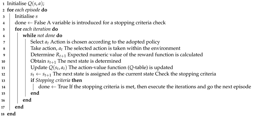
We adopted OpenAI Gym [53] tool for building environment for this study. It is based on episodic RL, where experience of each agent is divided into episodes. In initial state of each episode, we randomly localize the UAV BS and the users in a grid, and learning proceeds until the environment reaches one of the stopping criteria (this will be detailed in the following paragraphs). The main goal here is to maximize the total reward per episode and to decrease the number of episodes for achieving desired performance. RL steps in each episode are given in Algorithm 1, where s t and s t + 1 are the current and next states, respectively, and a t is the current state while R t + 1 is the expected value of the reward function.
Algorithm 1:Q-learning algorithm [52]
Algorithms 14 00302 i001
In this study, states refer to the position of the UAV in the grid. The agent in the developed Q-learning algorithm has seven action values for each state, which denote the agent action a t in UAV state of s t at time t. The possible actions for each state s t are hold, move up, move down, move left, move right, move forward, and move backward. The agent follows ϵ -greedy [52] policy to take random actions initially—which is referred to as exploring— and decays ϵ through iterations—which is referred to as exploiting— for decreasing random actions. Given that the main goal of this study is to optimize energy consumption of the UAV along with maximizing user coverage, the reward function in the proposed method is inline with the objective function in (23), and depends on the energy consumption and coverage.
The components of the developed Q-learning algorithm for the problem of UAV BS positioning are detailed in the following paragraphs.

4.1. Environment

We create discrete environment with finite size (grid) representing the state of UAV in OpenAI-Gym. The size of the grids in the environment-of-interest in this study is ( 25 , 25 , 12 ) , which is simulated with 10 m-resolution in each axis. Therefore, the real environment size becomes ( 250 , 250 , 120 ) in meters. These certain dimensions of the environment are chosen by considering both the computational burden and the reality of the work; such that, the environment should be in a size of some realistic area (and the UAV BS should be able to have sufficient degree of freedom in movement) while not bringing much computational burden (the simulation time should be reasonable for us to make some tuning during the design of the algorithm). However, we intuitively confirm that the developed algorithm would work in any environment size, as the UA BS can only move slightly at one iteration thereby extending the size of the environment would not affect the performance of the algorithm other than prolonging the simulation time.

4.2. Agent

The UAV BS in the state s t corresponds to the agent in this study. It will take an action, a t , in state s t , and it receives an observation and reward from the environment. Accordingly, it updates Q-table to learn the dynamics of the environment, and adapt itself to the changes. It is quite convenient to choose the UAV BS as the agent in the developed Q-learning algorithm, as it is the only one taking different actions; e.g., moving in different directions.

4.3. Actions

We consider seven different actions that agents can take. Let C 3 d = ( x u , y u , z u ) be the current position of the UAV BSs and C ^ 3 d be the position after an action taken, while r (in meters) denotes the step size in any direction. Then, the set of the actions, A , that the agent takes is as follows:
  • C ^ 3 d = ( x u , y u , z u + r ) : Move up (in z direction)
  • C ^ 3 d = ( x u , y u , z u r ) : Move down (in z direction)
  • C ^ 3 d = ( x u + r , y u , z u ) : Move left (in x direction)
  • C ^ 3 d = ( x u r , y u , z u ) : Move right (in x direction)
  • C ^ 3 d = ( x u , y u + r , z u ) : Move forward (in y direction)
  • C ^ 3 d = ( x u , y u r , z u ) : Move backward (in y direction)
  • C ^ 3 d = ( x u , y u , z u )   :Hold

4.4. States

We denote state s as the position of the UAV in a 3D space. We divide 3D space into grids (i.e., we discretized the state space) for having finite set of state that can be used in Q-learning. This state selection is inline with the criterion given in [52], such that the state should be affected by the actions that the agent takes. As such, the actions of the agent is fundamentally altering the 3D position of the UAV BS, which changes the state of the agent, which is also defined to be the 3D position of the agent.

4.5. Reward

To avoid the limitations of the work (or respect the constraints, in other words), a penalty mechanism is developed, such that the agents obtains a reward of -1 when the UAV BS
  • goes beyond the dimensions of the environment,
  • flies on the NFZ,
  • does not respect any other constraint in (23).
On the other hand, a reward function is designed for the cases where the UAV BS is not in one of the states listed above. Since the main goal is to optimize energy consumption along with maximizing number of user covered, the reward is defined inline with the optimization objective in (23), such that
R t + 1 = h ( C ) = w 1 n c w 2 E T .
The selection of the reward function as in (24) (i.e., making it equal to h ( C ) ) is a legitimate decision, because the the objective of the developed Q-learning algorithm is to maximize the reward, R, and the objective function in (23) is the maximization of h ( C ) . Thus, making the reward equal to h ( C ) is completely inline with the model in (23).

4.6. Policy

There are mainly two phases in the search of an agent to find optimal solution: (i) exploration and (ii) exploitation. In the former, agents enhance their current knowledge for a long-term benefit and make more accurate estimations of action-values. On the other hand, in the latter, agents take advantage of their experiences and perform greedy actions to obtain the most reward by exploiting the action-value estimate of agents. This behavior may not result in getting the most award and leads to suboptimal solutions. Namely, agents make more accurate action-values predictions when they explore, and receive more reward when they exploit. It is not possible to perform exploration and exploitation simultaneously which is known as exploration-exploitation dilemma. ϵ -greedy is a simple policy to create a balance between exploration and exploitation. ϵ identifies the probability of agent’s action to choose explore. This method is formulated as follows:
A t = Q t ( a ) ( 1 ϵ ) κ ϵ ,
where κ is a random variable with a discrete uniform distribution on A .
We follow an ϵ -greedy policy [52] to explore the environment by taking random actions in earlier iterations (exploration phase). As the iterations proceed (e.g., the number of the iterations get larger), we turn the exploration phase into the exploitation phase by decreasing ϵ with a decay-rate of 0.95 . This is done to allow the agent explore and acquire new experiences during the exploration phase, while in the exploitation phase it uses the obtained experience to converge to an optimal value.

4.7. Q-Table Update

We update the Q-table according the action a t in the state s t using:
Q ( s , a ) = : Q ( s , a ) + α [ R t + 1 + γ max ( Q ( s t + 1 ) ) Q ( s , a ) ]
where α is the learning-rate, and γ is the discount rate. Q-table update is crucial in storing the obtained experience as well as modifying it with the new data.

4.8. Initialization

In each episode, the UAV BS and the users are located randomly in the grid, so that the agent does not “memorize" (or it is called as overfitting in more technical terminology) a certain environment, instead produce a more generic model.

4.9. Episodes

The episode is considered as a snapshot of the environment in the problem formulation. The agent takes random actions in each episode and learn the environment using Q-table with (26) by evaluating the reward, R, through (24). When the the agent reaches stopping criteria, a new episode begins.

4.10. Stopping Criteria

If the predefined maximum number of iterations is reached or all the users are covered by the UAV BS, the current episode is terminated, and the algorithm goes into a new episode. The maximum number of iteration is set to 2000 in this work.

4.11. Complexity

The space complexity of Q-learning algorithm is the number of states times the number of actions. In this study, the UAV BS can take 7 actions as described earlier in Section 4. The 3D environment is discretized into (25, 25, 12), and thus the total number of states is 25 × 25 × 12 = 7,500.
The time complexity of proposed algorithm is the same as Q-learning which is O ( N a ) where N a is the number of actions. The current position of the UAV BS is the current state of the UAV BS and the action is performed accordingly by looking up the Q-table after training.

5. Performance Evaluation

In this section, we present the performance evaluation of the proposed methodology. After describing the simulation scenario, we introduce the benchmark method as well as the performance metrics, followed by presenting the obtained results and corresponding discussions. The parameters used in the simulation campaigns are given in Table 1.
The speed of the UAV BS is fixed in our model, as seen in Table 1. However, it is also an important parameter to considers, as it can have multiple impacts on the performance. For example, if the speed of the UAV BS is less than the average speed of the ground users, the UAV BS positions itself after the perfect time, which would degrade the overall performance as there is a delay in finding the optimal position. In the extreme scenario where the speed of the UAV BS is too less than the average speed of the users, a new positioning would be needed by the time the UAV BS arrives at the optimal position, as the users already moved, and the position of the UAV BS is not the optimal anymore. The same principle also applies to the case where the speed of the UAV BS is more than the average speed of the ground users, since there will be delay between the time that the UAV BS positions to an optimal point and the time that such point becomes the optimal position (because the users move slower than the UAV BS, which arrives the future optimal position early). The speed of the UAV BS requires a complex and detailed discussion, which would make this work lengthy and would also distract the main focus of the work. Therefore, we kept that discussion for a further study and focused only on how the UAV BS can be located in the case of moving users and NFZs.

5.1. Simulation Scenario

We implement a simulation scenario to evaluate the proposed Q-learning algorithm. An urban area of 250 × 250 m 2 —which is discretized by means of square-shaped grid—and n t = 100 total number of users (that are normally out-of-service from the terrestrial network) are considered. Consequently, the UAV can move in the discretized 3D space in terms of x, y, and z coordinates. Furthermore, due to the regulations, we impose a minimum and a maximum altitude of h min = 30 and h max = 120 m, respectively, and a certain number of NFZs, corresponding to specific not allowed grids. The users in the considered model are mobile and move at each time slot, and we consider a random walk model for the user mobility, meaning that the users move by a certain amount of distance from their original location in a random manner; such that the directions that they can move to have equal probability. The height from ground for all UEs is fixed to 1.5 m. Furthermore, we assume the directivity angle θ = 60 and the carrier frequency f c = 1 GHz. An initialization procedure is performed to explicate the initial conditions. In particular, the values for all the involved parameters are determined, considering arbitrary positions for the UAV BS and the users. An outage threshold is calculated considering a required minimum received power to establish and maintain with a certain QoS a connection between the UE and the UAV BS, called P r min . For a given transmitted power for the UAV BS, P t —lower than the maximum allowed value, P t max —, and the above-mentioned P r min , the path loss experienced by the UE, L, can be expressed by the following relation, L = P t P r min . Considering the 2D position of the UAV BS ( C 2 d ), the QoS constraint can be expressed in terms of L lower than L max [19], where L max is the path loss experienced by edge users. The footprint of the UAV BS, on the other hand, can be considered as a circle centered in the 2D position of the UAV BS ( C 2 d ).

5.2. Benchmark and Metrics

In this work, k-means algorithm is employed as a benchmark method, since it was widely used in similar problems [16]. k-means is an unsupervised clustering algorithm, where the data points are clustered according to certain features. In k-means, a centroid is assigned to each cluster and the objective is to place the centroids to the position which yields minimum cumulative distance to the data points. In particular, in the initialization of the algorithm, the centroids are placed randomly and the data points are assigned to each centroid to form a cluster, and the assignment is done in a way that each data point is assigned to the cluster that is closest to it in terms of Euclidian distance. Then, the centroids are moved towards to the center of their clusters, and this process iteratively continues until the convergence, where the centroids cannot be moved anymore.
Therefore, as this algorithm finds the position of the centroid, where the cumulative distance between the centroid and the data points is the minimum, it serves as a strong benchmark for this problem. In particular, if the UAV BS is considered as the centroid, while the ground users are the data points, the k-means algorithm positions the UAV BS at a point where it is closest to the ground users in terms of distance. Given that the distance is the primary parameter affecting the link quality between the transmitter and receiver, k-means algorithm becomes a appropriate benchmark. With this algorithm, we compute the centroid position related to the actual ground users’ positions. Consequently, the centroid corresponds to the best 2D position for UAV, in terms of respective distances between UAV and ground users.
Two different phases, one for training and one for testing, respectively, are performed to demonstrate the efficiency of the proposed Q-learning algorithm in terms of coverage and energy consumption. Regarding the coverage, we count the number of ground users, which are normally out of service from the terrestrial network, connected to the UAV BS, and the more users covered means a better performance in terms of the coverage. In the energy consumption, we measure the total energy consumption, E T , of the UAV BS while it is providing service to the users, and the less energy consumption refers to a better performance in terms of the energy consumption as the flight time of the UAV BS is prolonged.
During the training phase of the developed Q-learning algorithm, the simulation is conducted through a certain number of episodes to populate the related Q-table and consequently achieve the needed learning. A trade-off between coverage and energy consumption prioritization is considered both in training and testing phases. Specifically, five different experiments are performed with different values of the weights (e.g., w 1 and w 2 ) that are responsible of prioritizing the coverage or the energy consumption.

5.3. Simulation Results

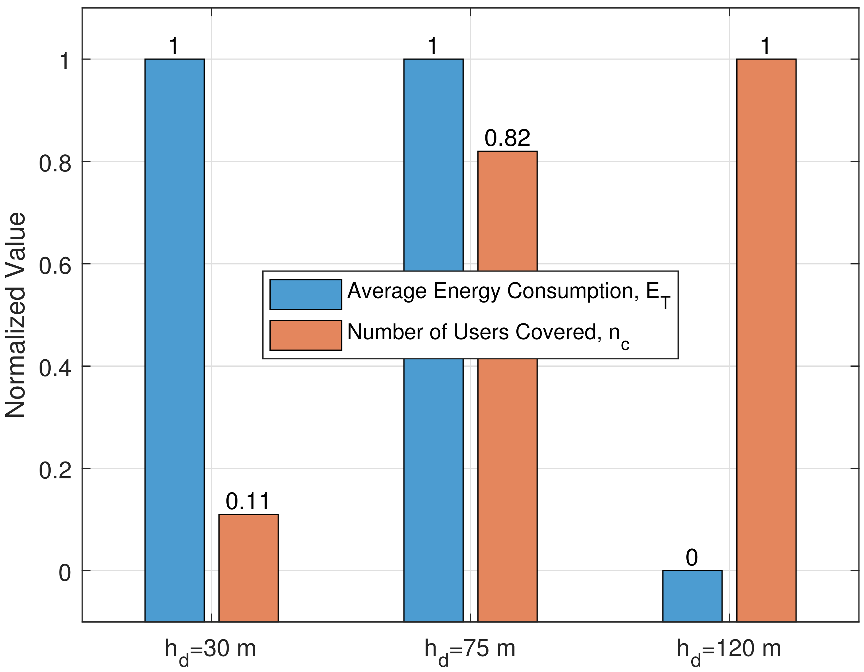
Figure 2 demonstrates the averaged and normalized results in terms of energy consumption (orange bars) and covered users (green bars) for different altitudes through k-means algorithm. Since the k-means algorithm determines the 2D position of the UAV BS, the altitude of the UAV BS should also be determined. Although there are different methods to determine the altitude, such as a trigonometric approach is used in [16], those usually do not consider the altitude regulations for the UAVs. In this work, on the other hand, considering such regulations, we used different fixed levels for the altitude of the UAV BS. In particular, three different altitude levels are considered: i) minimum allowed altitude ( h min = 30), maximum allowed altitude ( h max = 120 m), and the middle point between the two h max + h min 2 = 75 m.
From (11) it is understood that the value in the second case, i.e., with maximum allowed height of 120 m, can be assumed as the upper-bound in terms of coverage, since in this case the UAV is placed in the best 2D position with the maximum allowed height, that means the maximum achievable coverage area with respect to the size of the considered urban area, consequently obtaining the maximum number of covered users. A similar consideration can be done for this case (i.e., h max = 120 m) in terms of energy consumption. Since all ground users are covered at the first iteration, one of the stopping criteria is readily matched, thereby no movement is performed by the UAV, resulting in energy consumption due to mobility equals to zero. For the two remaining cases, with altitudes of 30 and 75 m, respectively, the results in terms of coverage can be considered as lower-bound and median values, since as previously stated, the coverage area, and subsequently, the number of covered user are highly dependent on the considered altitude of the UAV BS. Lastly, considering the energy consumption results, the UAV BS exploits the maximum number of allowed iterations attempting to match the stopping criteria for coverage, consequently resulting in the maximum value for energy consumption due to mobility.
We acknowledge that the number of users considered in the simulation campaigns would intuitively change the results in terms of the percentage of covered users, since the UAV BS has a certain amount of radio resources available and cannot serve all the users in case the number of users increased (when the total demand exceeds its available capacity). However, the goal of the agent (the UAV BS in our case) in this design is to maximize the number of users covered when w 2 is prioritized, and the simulation results confirm that the agent performs according to the prioritization conditions. Therefore, the scope of this work is to prove that the UAV BS is capable of maximizing the number of users covered and/or minimizing the energy consumption according to the prioritization policy. In the cases where the total demand is more than the capacity of a single UAV BS, then deploying multiple UAV BSs would be considered to accommodate more users in the system.
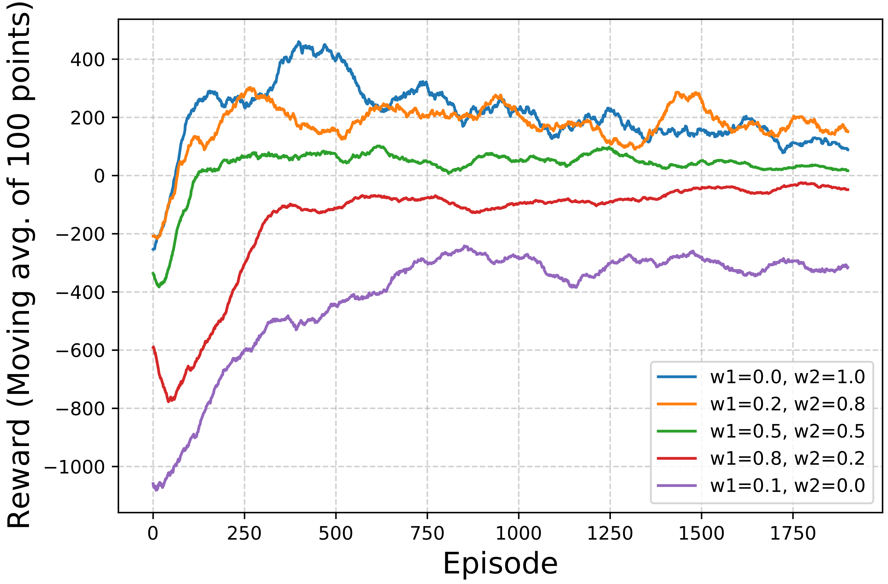
Figure 3 presents the results in terms of achieved rewards, after an initial phase, the convergence of the Q-learning algorithm occurs, demonstrating the effectiveness of the Q-learning algorithm. One of the important takeaway from the findings in Figure 3 is that, regardless of the weighting approach (e.g., for different w 1 and w 2 values), the designed Q-learning algorithm converges to the final reward. This confirms the proper design of the algorithm, and is a clear sign that it can work in various scenarios.
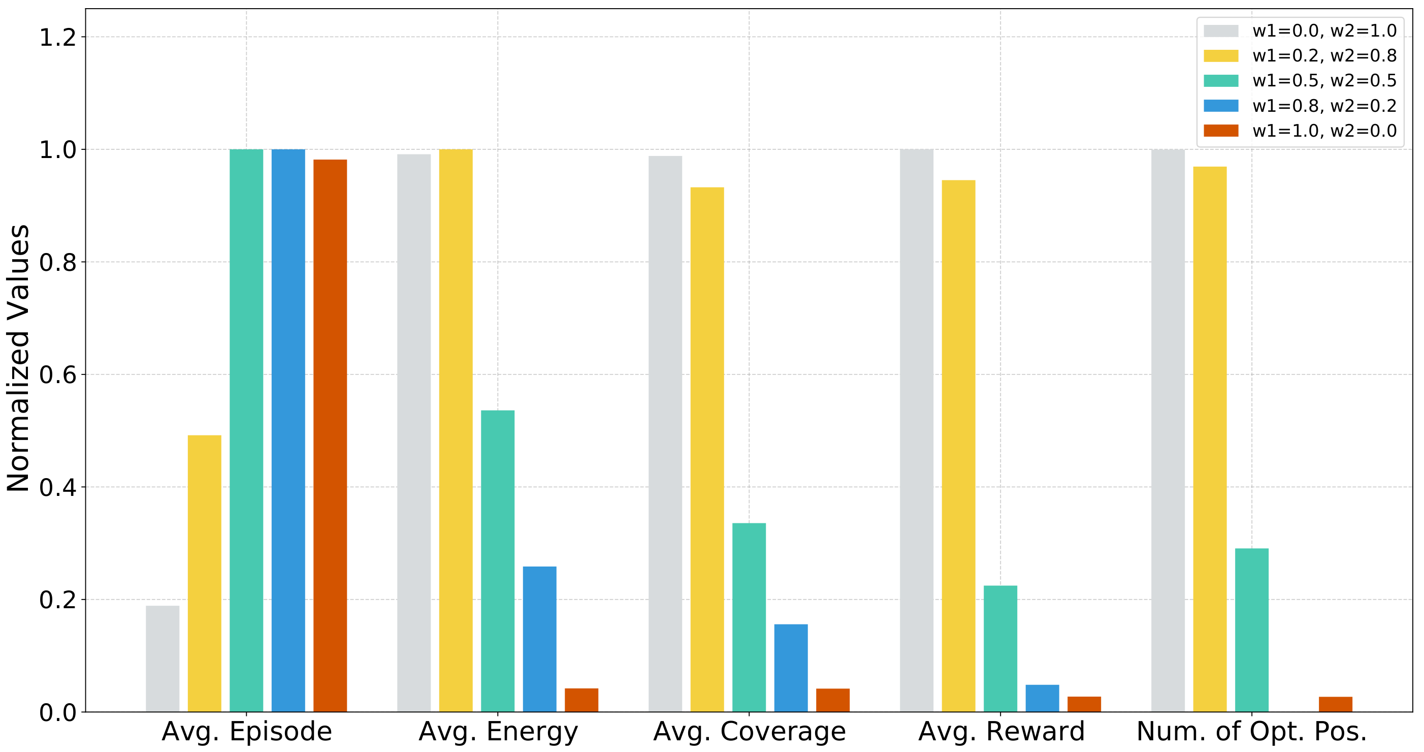
Following the above assumptions, the efficiency of the proposed Q-learning algorithm is verified through the testing phase, with the UAV BS positioning optimization through k-means as a benchmark. In this phase, the UAV BS is located in the above-mentioned simulated scenario and an arbitrary uniform distribution for the ground users is considered. The testing phase is conducted performing a certain number of runs, to average the results with regard to the specified parameters. Figure 4 shows the single UAV BS position optimization for different set of weights and the results are the normalized version of the average values between 0 and 1. The goodness of considering a trade-off between coverage and energy consumption, achieved by means of the two different weights, is mostly visible in two of the five experiments. In particular, for the w 1 = 0.2 and w 2 = 0.8, the best average energy consumption is achieved, whereas for the weights w 1 = 0.0 and w 2 = 1.0, best overall coverage, and rewards are obtained. In other words, the proper performances of the above-mentioned trade-off can be observed from the results in Figure 4. Effectively, when energy consumption is not prioritized, the UAV BS finds the optimum position in fewer episodes but at the expense of a higher energy consumption, conversely in the remaining cases. Therefore, the designed weighting mechanism works well, as the performance of the Q-learning algorithm is deeply affected by the numerical values of the weights. However, these results does not only affirm that the weighting mechanism works, but also gives superiority to the proposed approach, as it can converge to a solution according to the requirements of the network operators.

6. Conclusions

In this paper, a smart UAV BS positioning mechanism was proposed by taking altitude regulations as well as NFZs into account along with some hard constraints, including maximum transmit power and directivity of the UAV BS antenna, to provide sustainable wireless coverage and services to the ground users under more realistic conditions. As such, firstly, two different optimization models were developed for the minimization of the energy consumption and maximization of the number of users covered. Then, these two distinctive models are combined with a weighting mechanism, and a multiobjective optimization problem formulation was developed. With the developed weighting mechanism, wireless networks operators become capable of positioning the UAV BSs according to their requirements by relatively ranking the energy consumption and the number of users covered. We proposed a Q-learning-based approach for UAV-assisted communication systems, and the OpenAI Gym tool was used to build the RL environment. The objective is to find the optimal position of the UAV and minimize the energy consumption while maximizing the number of users covered. The results demonstrate that the proposed solution outperforms the baseline k-means method in terms of covered users, while achieving the desired minimization of the energy consumption.
Since a single UAV BS has a certain amount of radio resources and is capable of accommodating a limited number of users, in future we plan to investigate the UAV-assisted coverage extension problem in multi-UAV scenario, wherein more than one UAV BS are deployed to serve to the ground users to further maximize the number of connected users. That would be a more challenging problem due to the fact that the interference between the UAV BSs will be another aspect to consider, as such interference will have an impact on the communication performance and so the positions of the UAV BSs. Future work would also consider to investigate the impacts of the speed of the UAV BS in the overall performance. Moreover, as in a realistic case, having a dynamic speed for the UAV BS, in which case the speed should also be optimized, will be also considered.

Author Contributions

Conceptualization, M.O. and M.Z.A.; Investigation, G.C.V.; Methodology, İ.A., M.O. and G.C.V.; Software, İ.A. and G.C.V.; Validation, İ.A. and G.C.V.; Visualization, İ.A. and G.C.V.; Writing—original draft, İ.A., M.O., G.C.V. and M.Z.A.; Writing—review & editing, M.O. All authors have read and agreed to the published version of the manuscript.

Funding

This research received no external funding.

Data Availability Statement

Not applicable.

Conflicts of Interest

The authors declare no conflict of interest.

References

  1. Ericsson. Ericsson Mobility Report; Technical report; Ericsson: Stockholm, Sweden, 2021. [Google Scholar]
  2. Al-Fuqaha, A.; Guizani, M.; Mohammadi, M.; Aledhari, M.; Ayyash, M. Internet of Things: A Survey on Enabling Technologies, Protocols, and Applications. IEEE Commun. Surv. Tutorials 2015, 17, 2347–2376. [Google Scholar] [CrossRef]
  3. Shafi, M.; Molisch, A.F.; Smith, P.J.; Haustein, T.; Zhu, P.; De Silva, P.; Tufvesson, F.; Benjebbour, A.; Wunder, G. 5G: A Tutorial Overview of Standards, Trials, Challenges, Deployment, and Practice. IEEE J. Sel. Areas Commun. 2017, 35, 1201–1221. [Google Scholar] [CrossRef]
  4. Jameel, F.; Faisal; Haider, M.A.A.; Butt, A.A. Massive MIMO: A survey of recent advances, research issues and future directions. In Proceedings of the 2017 International Symposium on Recent Advances in Electrical Engineering (RAEE), Islamabad, Pakistan, 24–26 October 2017; pp. 1–6. [Google Scholar] [CrossRef]
  5. Busari, S.A.; Huq, K.M.S.; Mumtaz, S.; Dai, L.; Rodriguez, J. Millimeter-Wave Massive MIMO Communication for Future Wireless Systems: A Survey. IEEE Commun. Surv. Tutorials 2018, 20, 836–869. [Google Scholar] [CrossRef]
  6. Rappaport, T.S.; Xing, Y.; MacCartney, G.R.; Molisch, A.F.; Mellios, E.; Zhang, J. Overview of Millimeter Wave Communications for Fifth-Generation (5G) Wireless Networks—With a Focus on Propagation Models. IEEE Trans. Antennas Propag. 2017, 65, 6213–6230. [Google Scholar] [CrossRef]
  7. 3GPP. 5G; NR; Base Station (BS) Radio Transmission and Reception. Technical Specification (TS) 38.104. Available online: https://portal.3gpp.org/desktopmodules/Specifications/SpecificationDetails.aspx?specificationId=3202 (accessed on 1 September 2021).
  8. Mozaffari, M.; Saad, W.; Bennis, M.; Nam, Y.H.; Debbah, M. A Tutorial on UAVs for Wireless Networks: Applications, Challenges, and Open Problems. IEEE Commun. Surv. Tutorials 2019, 21, 2334–2360. [Google Scholar] [CrossRef] [Green Version]
  9. Klaine, P.V.; Imran, M.A.; Onireti, O.; Souza, R.D. A Survey of Machine Learning Techniques Applied to Self-Organizing Cellular Networks. IEEE Commun. Surv. Tutorials 2017, 19, 2392–2431. [Google Scholar] [CrossRef] [Green Version]
  10. Zhang, C.; Patras, P.; Haddadi, H. Deep Learning in Mobile and Wireless Networking: A Survey. IEEE Commun. Surv. Tutorials 2019, 21, 2224–2287. [Google Scholar] [CrossRef] [Green Version]
  11. Morocho Cayamcela, M.E.; Lim, W. Artificial Intelligence in 5G Technology: A Survey. In Proceedings of the 2018 International Conference on Information and Communication Technology Convergence (ICTC), Jeju Island, Korea, 17–19 October 2018; pp. 860–865. [Google Scholar] [CrossRef]
  12. Sun, Y.; Peng, M.; Zhou, Y.; Huang, Y.; Mao, S. Application of Machine Learning in Wireless Networks: Key Techniques and Open Issues. IEEE Commun. Surv. Tutorials 2019, 21, 3072–3108. [Google Scholar] [CrossRef] [Green Version]
  13. Zhang, H.; Dai, L. Mobility Prediction: A Survey on State-of-the-Art Schemes and Future Applications. IEEE Access 2019, 7, 802–822. [Google Scholar] [CrossRef]
  14. Dogra, A.; Jha, R.K.; Jain, S. A Survey on beyond 5G network with the advent of 6G: Architecture and Emerging Technologies. IEEE Access 2020. [Google Scholar] [CrossRef]
  15. Lu, Y.; Zheng, X. 6G: A survey on technologies, scenarios, challenges, and the related issues. J. Ind. Inf. Integr. 2020, 19, 100158. [Google Scholar] [CrossRef]
  16. Ozturk, M.; Nadas, J.P.B.; Klaine, P.H.V.; Hussain, S.; Imran, M.A. Clustering Based UAV Base Station Positioning for Enhanced Network Capacity. In Proceedings of the 2019 International Conference on Advances in the Emerging Computing Technologies (AECT), Medina, Saudi Arabia, 8–10 December 2019; pp. 1–6. [Google Scholar] [CrossRef]
  17. Zhang, X.; Duan, L. Energy-Saving Deployment Algorithms of UAV Swarm for Sustainable Wireless Coverage. IEEE Trans. Veh. Technol. 2020, 69, 10320–10335. [Google Scholar] [CrossRef]
  18. de Paula Parisotto, R.; Klaine, P.V.; Nadas, J.P.B.; Souza, R.D.; Brante, G.; Imran, M.A. Drone Base Station Positioning and Power Allocation using Reinforcement Learning. In Proceedings of the 2019 16th International Symposium on Wireless Communication Systems (ISWCS), Oulu, Finland, 27–30 August 2019; pp. 213–217. [Google Scholar] [CrossRef]
  19. Wang, L.; Hu, B.; Chen, S. Energy Efficient Placement of a Drone Base Station for Minimum Required Transmit Power. IEEE Wirel. Commun. Lett. 2020, 9, 2010–2014. [Google Scholar] [CrossRef]
  20. Donevski, I.; Nielsen, J.J. Dynamic Standalone Drone-Mounted Small Cells. In Proceedings of the 2020 European Conference on Networks and Communications (EuCNC), Dubrovnik, Croatia, 16–17 June 2020; pp. 342–347. [Google Scholar] [CrossRef]
  21. Al-Hourani, A.; Kandeepan, S.; Lardner, S. Optimal LAP Altitude for Maximum Coverage. IEEE Wirel. Commun. Lett. 2014, 3, 569–572. [Google Scholar] [CrossRef] [Green Version]
  22. Mozaffari, M.; Saad, W.; Bennis, M.; Debbah, M. Unmanned Aerial Vehicle With Underlaid Device-to-Device Communications: Performance and Tradeoffs. IEEE Trans. Wirel. Commun. 2016, 15, 3949–3963. [Google Scholar] [CrossRef]
  23. Becvar, Z.; Mach, P.; Nikooroo, M. Reducing Energy Consumed by Repositioning of Flying Base Stations Serving Mobile Users. In Proceedings of the 2020 IEEE Wireless Communications and Networking Conference (WCNC), Seoul, Korea, 25–28 May 2020; pp. 1–7. [Google Scholar] [CrossRef]
  24. Qi, H.; Hu, Z.; Huang, H.; Wen, X.; Lu, Z. Energy Efficient 3-D UAV Control for Persistent Communication Service and Fairness: A Deep Reinforcement Learning Approach. IEEE Access 2020, 8, 53172–53184. [Google Scholar] [CrossRef]
  25. Dorling, K.; Heinrichs, J.; Messier, G.G.; Magierowski, S. Vehicle Routing Problems for Drone Delivery. IEEE Trans. Syst. Man, Cybern. Syst. 2017, 47, 70–85. [Google Scholar] [CrossRef] [Green Version]
  26. Xu, C.; Liao, X.; Tan, J.; Ye, H.; Lu, H. Recent Research Progress of Unmanned Aerial Vehicle Regulation Policies and Technologies in Urban Low Altitude. IEEE Access 2020, 8, 74175–74194. [Google Scholar] [CrossRef]
  27. Fotouhi, A.; Qiang, H.; Ding, M.; Hassan, M.; Giordano, L.G.; Garcia-Rodriguez, A.; Yuan, J. Survey on UAV Cellular Communications: Practical Aspects, Standardization Advancements, Regulation, and Security Challenges. IEEE Commun. Surv. Tutorials 2019, 21, 3417–3442. [Google Scholar] [CrossRef] [Green Version]
  28. Patané, G.M.M.; Valastro, G.C.; Sambo, Y.A.; Ozturk, M.; Hussain, S.; Imran, M.A.; Panno, D. Flexible SDN/NFV-based SON testbed for 5G mobile networks. In Proceedings of the 2019 IEEE/ACM 23rd International Symposium on Distributed Simulation and Real Time Applications (DS-RT), Cosenza, Italy, 7–9 October2019; pp. 1–8. [Google Scholar] [CrossRef]
  29. Sambo, Y.A.; Valastro, G.C.; Patané, G.M.M.; Ozturk, M.; Hussain, S.; Imran, M.A.; Panno, D. Motion Sensor-Based Small Cell Sleep Scheduling for 5G Networks. In Proceedings of the 2019 IEEE 24th International Workshop on Computer Aided Modeling and Design of Communication Links and Networks (CAMAD), Limassol, Cyprus, 11–13 September 2019; pp. 1–5. [Google Scholar] [CrossRef] [Green Version]
  30. Mozaffari, M.; Saad, W.; Bennis, M.; Debbah, M. Mobile Unmanned Aerial Vehicles (UAVs) for Energy-Efficient Internet of Things Communications. IEEE Trans. Wirel. Commun. 2017, 16, 7574–7589. [Google Scholar] [CrossRef]
  31. Pang, Y.; Zhang, Y.; Gu, Y.; Pan, M.; Han, Z.; Li, P. Efficient data collection for wireless rechargeable sensor clusters in Harsh terrains using UAVs. In Proceedings of the 2014 IEEE Global Communications Conference, Austin, TX, USA, 8–12 December 2014; pp. 234–239. [Google Scholar] [CrossRef]
  32. Liu, X.; Ansari, N. Resource Allocation in UAV-Assisted M2M Communications for Disaster Rescue. IEEE Wirel. Commun. Lett. 2019, 8, 580–583. [Google Scholar] [CrossRef]
  33. Bithas, P.S.; Michailidis, E.T.; Nomikos, N.; Vouyioukas, D.; Kanatas, A.G. A Survey on Machine-Learning Techniques for UAV-Based Communications. Sensors 2019, 19, 5170. [Google Scholar] [CrossRef] [PubMed] [Green Version]
  34. Mozaffari, M.; Saad, W.; Bennis, M.; Debbah, M. Drone Small Cells in the Clouds: Design, Deployment and Performance Analysis. In Proceedings of the 2015 IEEE Global Communications Conference (GLOBECOM), San Diego, CA, USA, 6–10 December 2015; pp. 1–6. [Google Scholar] [CrossRef] [Green Version]
  35. Mozaffari, M.; Saad, W.; Bennis, M.; Debbah, M. Efficient Deployment of Multiple Unmanned Aerial Vehicles for Optimal Wireless Coverage. IEEE Commun. Lett. 2016, 20, 1647–1650. [Google Scholar] [CrossRef]
  36. Hayajneh, A.M.; Zaidi, S.A.R.; McLernon, D.C.; Ghogho, M. Drone Empowered Small Cellular Disaster Recovery Networks for Resilient Smart Cities. In Proceedings of the 2016 IEEE International Conference on Sensing, Communication and Networking (SECON Workshops), London, UK, 27–30 June 2016; pp. 1–6. [Google Scholar] [CrossRef] [Green Version]
  37. Bor-Yaliniz, R.I.; El-Keyi, A.; Yanikomeroglu, H. Efficient 3-D placement of an aerial base station in next generation cellular networks. In Proceedings of the 2016 IEEE International Conference on Communications (ICC), Kuala Lumpur, Malaysia, 23–27 May 2016; pp. 1–5. [Google Scholar] [CrossRef] [Green Version]
  38. Kalantari, E.; Yanikomeroglu, H.; Yongacoglu, A. On the Number and 3D Placement of Drone Base Stations in Wireless Cellular Networks. In Proceedings of the 2016 IEEE 84th Vehicular Technology Conference (VTC-Fall), Montréal, QC, Canada, 18–21 September 2016; pp. 1–6. [Google Scholar] [CrossRef] [Green Version]
  39. Košmerl, J.; Vilhar, A. Base stations placement optimization in wireless networks for emergency communications. In Proceedings of the 2014 IEEE International Conference on Communications Workshops (ICC), Sydney, NSW, Australia, 10–14 June 2014; pp. 200–205. [Google Scholar] [CrossRef]
  40. Zhan, P.; Yu, K.; Lee Swindlehurst, A. Wireless Relay Communications using an Unmanned Aerial Vehicle. In Proceedings of the 2006 IEEE 7th Workshop on Signal Processing Advances in Wireless Communications, Cannes, France, 2–5 July 2006; pp. 1–5. [Google Scholar] [CrossRef] [Green Version]
  41. Mohamed, E.M.; Hashima, S.; Aldosary, A.; Hatano, K.; Abdelghany, M.A. Gateway Selection in Millimeter Wave UAV Wireless Networks Using Multi-Player Multi-Armed Bandit. Sensors 2020, 20, 3947. [Google Scholar] [CrossRef] [PubMed]
  42. Wu, Q.; Zeng, Y.; Zhang, R. Joint Trajectory and Communication Design for Multi-UAV Enabled Wireless Networks. IEEE Trans. Wirel. Commun. 2018, 17, 2109–2121. [Google Scholar] [CrossRef] [Green Version]
  43. Jiang, F.; Swindlehurst, A.L. Optimization of UAV Heading for the Ground-to-Air Uplink. IEEE J. Sel. Areas Commun. 2012, 30, 993–1005. [Google Scholar] [CrossRef] [Green Version]
  44. Zeng, Y.; Zhang, R.; Lim, T.J. Throughput Maximization for UAV-Enabled Mobile Relaying Systems. IEEE Trans. Commun. 2016, 64, 4983–4996. [Google Scholar] [CrossRef]
  45. Cabreira, T.M.; Franco, C.D.; Ferreira, P.R.; Buttazzo, G.C. Energy-Aware Spiral Coverage Path Planning for UAV Photogrammetric Applications. IEEE Robot. Autom. Lett. 2018, 3, 3662–3668. [Google Scholar] [CrossRef]
  46. Shao, X.; Gong, Y.J.; Zhan, Z.H.; Zhang, J. Bipartite Cooperative Coevolution for Energy-Aware Coverage Path Planning of UAVs. IEEE Trans. Artif. Intell. 2021. [Google Scholar] [CrossRef]
  47. Yang, D.; Dan, Q.; Xiao, L.; Liu, C.; Cuthbert, L. An efficient trajectory planning for cellular-connected UAV under the connectivity constraint. China Commun. 2021, 18, 136–151. [Google Scholar] [CrossRef]
  48. Sun, G.; Li, J.; Liu, Y.; Liang, S.; Kang, H. Time and Energy Minimization Communications Based on Collaborative Beamforming for UAV Networks: A Multi-objective Optimization Method. IEEE J. Sel. Areas Commun. 2021. [Google Scholar] [CrossRef]
  49. Yu, Y.; Tang, J.; Huang, J.; Zhang, X.; So, D.K.C.; Wong, K.K. Multi-Objective Optimization for UAV-Assisted Wireless Powered IoT Networks Based on Extended DDPG Algorithm. IEEE Trans. Commun. 2021. [Google Scholar] [CrossRef]
  50. Zeng, Y.; Xu, J.; Zhang, R. Energy Minimization for Wireless Communication With Rotary-Wing UAV. IEEE Trans. Wirel. Commun. 2019, 18, 2329–2345. [Google Scholar] [CrossRef] [Green Version]
  51. Arani, A.H.; Hu, P.; Zhu, Y. Re-envisioning Space-Air-Ground Integrated Networks: Reinforcement Learning for Link Optimization. In Proceedings of the ICC 2021—IEEE International Conference on Communications, Montreal, QC, Canada, 14–23 June 2021; pp. 1–7. [Google Scholar] [CrossRef]
  52. Sutton, R.S.; Barto, A.G. Reinforcement Learning: An Introduction; MIT Press: Cambridge, MA, USA, 2018. [Google Scholar]
  53. Brockman, G.; Cheung, V.; Pettersson, L.; Schneider, J.; Schulman, J.; Tang, J.; Zaremba, W. OpenAI Gym. arXiv preprint arXiv:1606.01540.
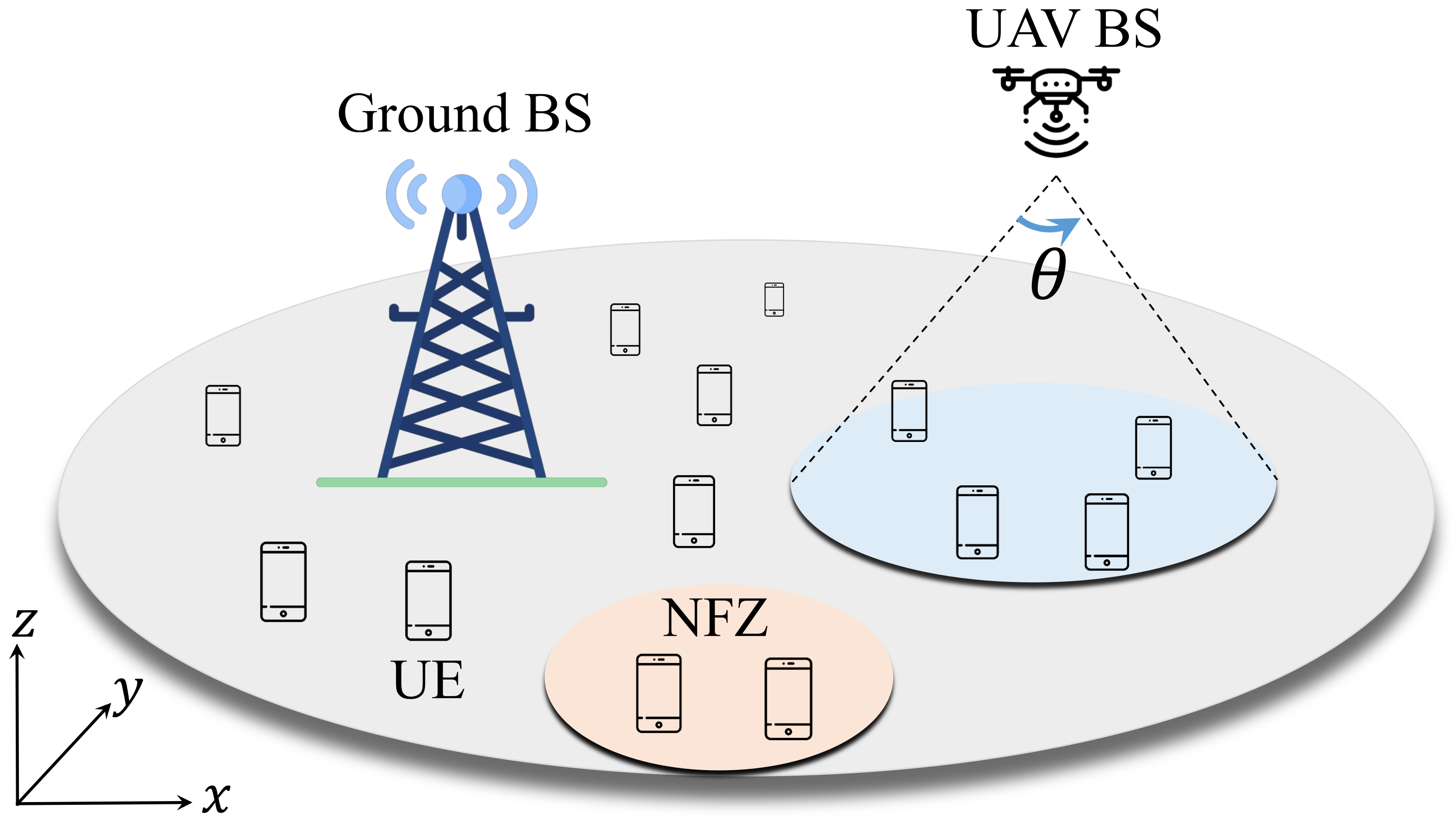
Figure 1. Considered scenario depicting a ground macro BS that provides a wide-range coverage and UAV BS that provides additional capacity to the cellular network. A no-fly zone (NFZ), over which the UAV BSs are prohibited to fly, is also illustrated.
Algorithms 14 00302 g001
Figure 2. Single UAV positioning for different altitudes through k-means.
Algorithms 14 00302 g002
Figure 3. Q-learning algorithm convergence in terms of rewards for different set of weights for 2000 episodes.
Algorithms 14 00302 g003
Figure 4. Monte Carlo test results. Single UAV position optimisation comparison for different set of weights.
Algorithms 14 00302 g004
Table 1. Simulation parameters.
ParameterValue
General
Carrier frequency, f c 1 GHz
Antenna directivity angle, θ 60
Minimum UAV height, h min 30 m
Maximum UAV height, h max 120 m
Urban Area250 × 250 m 2
Total number of users, n t 100
Height from ground for all UEs1.5 m
Speed of light, c 3 × 10 8 m/s
η LoS1.6 dB
η NLoS23 dB
Parameter of A2G path loss model, Ψ 12.08
Parameter of A2G path loss model, ζ 0.11
Number of rotors, M4
Fluid density of the air, ρ 1.2 Kg/m 3
Rotor disk radius, β 0.25 m
Weight of the frame1.5 Kg
Weight of the battery and payload2 Kg
Bandwidth180 kHz
Transmit power, P t 30 dBm (1 W)
On-board circuit power, P cu 0.01 W
Duration of hovering of UAV, t h 1 s
Duration to communication of UAV, t cm 1 s
Velocity of the UAV, v30 m/s
Angular velocity, ω 40 rad/s
Drag coefficient0.025
Rotor chord, c b 0.022 m
Reference frontal area of the UAV0.192 m 2
Q -learning
Discount rate, γ 0.9
Epsilon, ϵ 1
Epsilon decay, ϵ -decay0.95
Learning rate, α 0.9
Learning rate decay, α -decay 1 × 10 4
Publisher’s Note: MDPI stays neutral with regard to jurisdictional claims in published maps and institutional affiliations.