Communication

Multiscale Finite Element Analysis of Warping Suppression in Microelectronics with Graded SiC/Al Composites

Guangdong Provincial Key Laboratory of Electronic Functional Materials and Devices, Huizhou University, Huizhou 516001, China
*
Authors to whom correspondence should be addressed.
Materials 2025, 18(16), 3788; https://doi.org/10.3390/ma18163788
Submission received: 3 July 2025 / Revised: 22 July 2025 / Accepted: 28 July 2025 / Published: 12 August 2025

Abstract

High-power microelectronic packaging faces critical thermomechanical failures under rapid thermal cycling, primarily due to interfacial stress concentration and warping in conventional homogeneous heat sinks. To address this challenge, this study proposes a novel functionally graded SiC/Al composite with a tailored thermal expansion coefficient (CTE) gradient, designed to achieve adaptive thermal expansion matching between the chip and heat sink. Through multiscale finite element analysis, the stress–strain behavior and warping characteristics of homogeneous (Cu and Al) and gradient materials were systematically investigated. The results show that the gradient SiC/Al design significantly reduces the peak thermal stress and maximum warping deformation. The progressive CTE transition effectively mitigates abrupt interfacial strain jumps and extends device lifespan under extreme thermal loads. This advancement positions gradient SiC/Al composites as a key enabler for next-generation high-density packaging and power electronics requiring cyclic thermal stability. The study provides both theoretical insights into thermomechanical coupling and practical guidelines for designing robust electronic packaging solutions.

1. Introduction

The relentless advancement in microelectronic technology has driven an exponential increase in power density and integration levels of modern devices, exemplified by 3D ICs and AI accelerators exceeding 500 W/cm2 thermal loads [1,2,3]. This escalation intensifies thermomechanical challenges, where interfacial stress concentrations and warping deformation in packaging materials account for over 50% of field failures in high-power electronics [4]. Conventional homogeneous heat sink materials (e.g., Cu and Al) face inherent limitations due to mismatched thermal expansion coefficients (CTE) with semiconductor substrates (Si: 2.5 ppm/°C vs. Cu: 16.7 ppm/°C), generating tensile stresses exceeding 200 MPa under thermal cycling [5,6]. Such stresses induce delamination, cracking, and warping deflection in Cu-based modules, severely compromising device reliability in applications like electric vehicle inverters and data center GPUs. High-SiC-content SiC/Al composite materials offer advantages such as high thermal conductivity, low coefficient of thermal expansion, high specific strength, high specific stiffness, wear resistance, and low density, making them highly promising for applications in power electronics, aerospace, and military sectors.
While functionally graded materials (FGMs) have emerged as promising solutions by spatially tailoring material properties [7,8,9], the existing studies predominantly focus on thermal conductivity enhancement or uniform CTE reduction [10,11,12]. Critical gaps remain in systematically optimizing CTE gradients to mitigate interfacial strain mismatches. The latest research by Jia et al. [13] demonstrated a 60% increase in tensile strength through gradient structures, but lacked quantitative analysis of stress suppression. Similarly, Zhao et al. reported improved thermal stability in graded SiC/Al composites but did not correlate CTE gradients with operational temperature limits [14]. While recent studies on FGMs have improved thermal stability or mechanical strength, they lack a systematic framework for optimizing CTE gradients to mitigate interfacial strain mismatches under cyclic thermal loads. Unlike previous works focusing on uniform CTE reduction or thermal conductivity enhancement, this study pioneers a layer-wise CTE gradient design integrated with multiscale thermomechanical coupling analysis, enabling adaptive thermal expansion matching between heterogeneous materials. This approach not only quantifies stress suppression but also establishes operational temperature limits for gradient materials, addressing a critical gap in FGM research for high-power electronics.
To address these limitations, this study introduces a layer-wise CTE gradient design in SiC/Al composites (6.5–9.0 ppm/°C), enabling adaptive thermal expansion matching between chips and heat sinks. A coupled thermomechanical framework is established through multiscale finite element modeling, which integrates transient temperature fields with spatially varying CTE distributions—a methodology that was previously absent in functional gradient materials (FGMs) research. This approach not only quantifies the reduction in warping but also defines the maximum operational temperature of gradient materials under extreme thermal loads (125 °C). These studies will advance the fundamental understanding of thermomechanical coupling in FGMs while offering practical guidance for the next-generation packaging of 5G infrastructure and high-power chip integration systems.

2. Simulation and Computational Methods

2.1. Definition of Numerical Model

The microelectronic chip cooler is modeled as a tri-layer structure (Figure 1), comprising a silicon semiconductor chip (10 × 10 × 0.5 mm3), a 0.1 mm thick silver-filled epoxy adhesive interface layer (thermal conductivity: 5 W/(m·K)), and a 195 × 110 × 13 mm3 heat sink. To address CTE mismatch-induced failures in conventional homogeneous materials (e.g., Cu: 16.7 ppm/°C vs. Si: 2.5 ppm/°C), we propose a functionally graded SiC/Al composite heat sink with a continuous CTE gradient along the thickness direction (6.5–9.0 ppm/°C). This gradient is achieved by varying the SiC volume fraction through a powder metallurgy-based layer-wise stacking process, ensuring smooth transition of thermomechanical properties.
The numerical model incorporates temperature-dependent material properties (Table 1), including nonlinear thermal expansion coefficients and anisotropic thermal conductivity for the gradient layers. Transient thermal loads are defined by a chip power dissipation profile ranging from 50 W to 300 W (5 s ramp-up), with convective cooling (h = 1200 W/m2·K) applied to the fin surfaces. Fixed constraints are imposed at the heat sink mounting holes to simulate real-world assembly conditions.

2.2. Finite Element Simulation

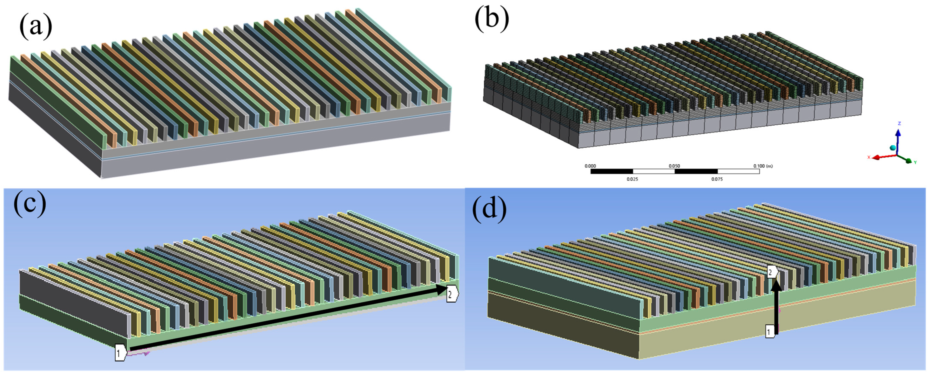
The thermomechanical behavior of the packaging system was analyzed using ANSYS 2021 R2 employing a sequentially coupled approach to integrate steady-state thermal analysis with static structural mechanics. Hexahedral-dominated meshes (Figure 2b) were generated with local refinement (0.2 mm at critical interfaces) to resolve thermal gradients. Transient thermal analysis was performed with a Newton–Raphson nonlinear solver, incorporating temperature-dependent material properties for gradient layers (Figure 1) through user-defined field functions. The chip power profile followed a trapezoidal waveform (50–300 W, 5 s ramp/plateau), while convective cooling (h = 1200 W/m2·K) was applied to fin surfaces using SURF152 elements. The 5 s ramp-up to 300W thermal load condition simulates the real transient scenarios of high-power electronic devices, such as the IGBT switching surge in electric vehicle inverters. Structural analysis utilized the full Newton–Raphson method with large deformation effects activated, resolving contact nonlinearities at interfaces via augmented Lagrange formulation (penalty factor: 0.1; friction coefficient: 0.25). This paper investigates the stress and strain in the axial and radial directions using simulation models, as shown in Figure 2c,d.

3. Simulation and Discussion

3.1. Thermal and Mechanical Behavior of Homogeneous Materials

(1)
Thermal Performance Analysis
Steady-state thermal simulations of homogeneous the Cu, Al, and SiC/Al composite heat sinks reveal distinct thermal management capabilities. As shown in Figure 3 and Table 2, the Cu heat sink exhibits the highest base heat flux (1.0637 W/mm2) and lowest maximum temperature (92.2 °C), attributed to its superior thermal conductivity (396.7 W/(m·K)). In contrast, the Al and SiC/Al heat sinks show reduced heat flux (0.92556 W/mm2 and 0.93112 W/mm2, respectively) and higher peak temperatures (98.99 °C and 98.69 °C), consistent with their lower thermal conductivities (155.3 W/(m·K) and 160 W/(m·K)). Notably, the SiC/Al composite demonstrates a 12.5% lower temperature gradient (ΔT = 33.3 °C) compared to Al (ΔT = 34.1 °C), suggesting improved thermal uniformity despite comparable bulk conductivity—a phenomenon linked to its reduced CTE mismatch with the silicon chip (6.5 ppm/°C vs. Si: 2.5 ppm/°C).
(2)
Thermomechanical Stress Behavior
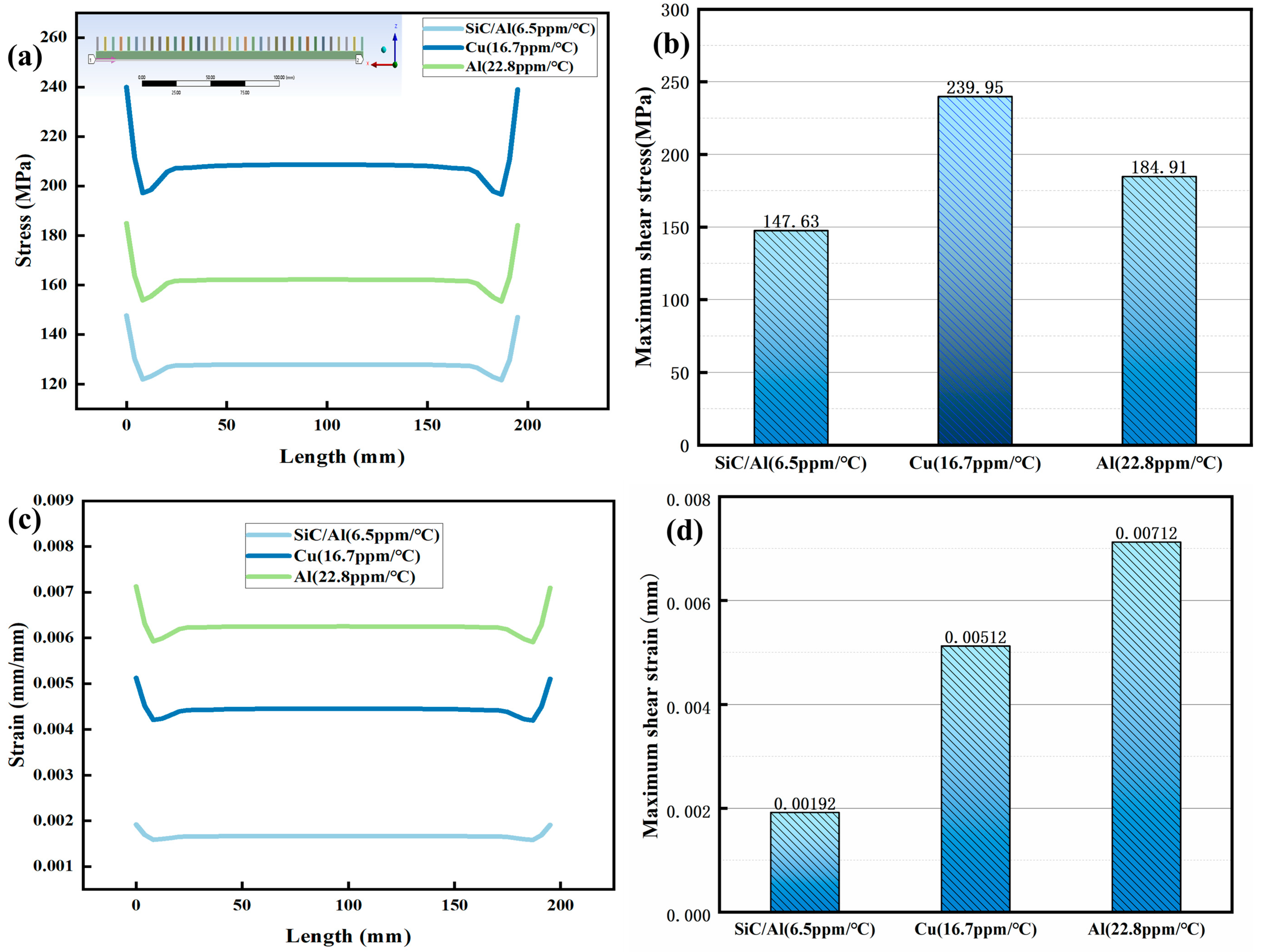
The axial stress–strain analysis of Figure 4 and Figure 5 indicates that homogeneous materials exhibit significant differences during thermal cycling (25–200 °C). Cu exhibits the highest thermal stress escalation, from 4.0 MPa at 25 °C to 239.95 MPa at 200 °C, exceeding the yield strength of typical solder alloys (150–200 MPa) and risking interfacial delamination. This aligns with the thermal stress formula:
σ   =   E α Δ T
wherein E represents the elastic modulus (Cu: 126 GPa), α is the CTE (Coefficient of Thermal Expansion), and ΔT is the temperature difference. While Al shows lower peak stress (184.91 MPa), its high plasticity induces excessive strain (0.00712 mm), causing permanent deformation (Figure 5c). The mechanism is consistent with that of “plastic strain accumulation leading to fatigue failure in Al” as described in reference [15]. The SiC/Al composite outperforms both, limiting stress to 147.63 MPa and strain to 0.00192 mm—a 38.4% stress reduction compared to Cu—attributed to its CTE (6.5 ppm/°C) being 2.6 ppm/°C closer to silicon.
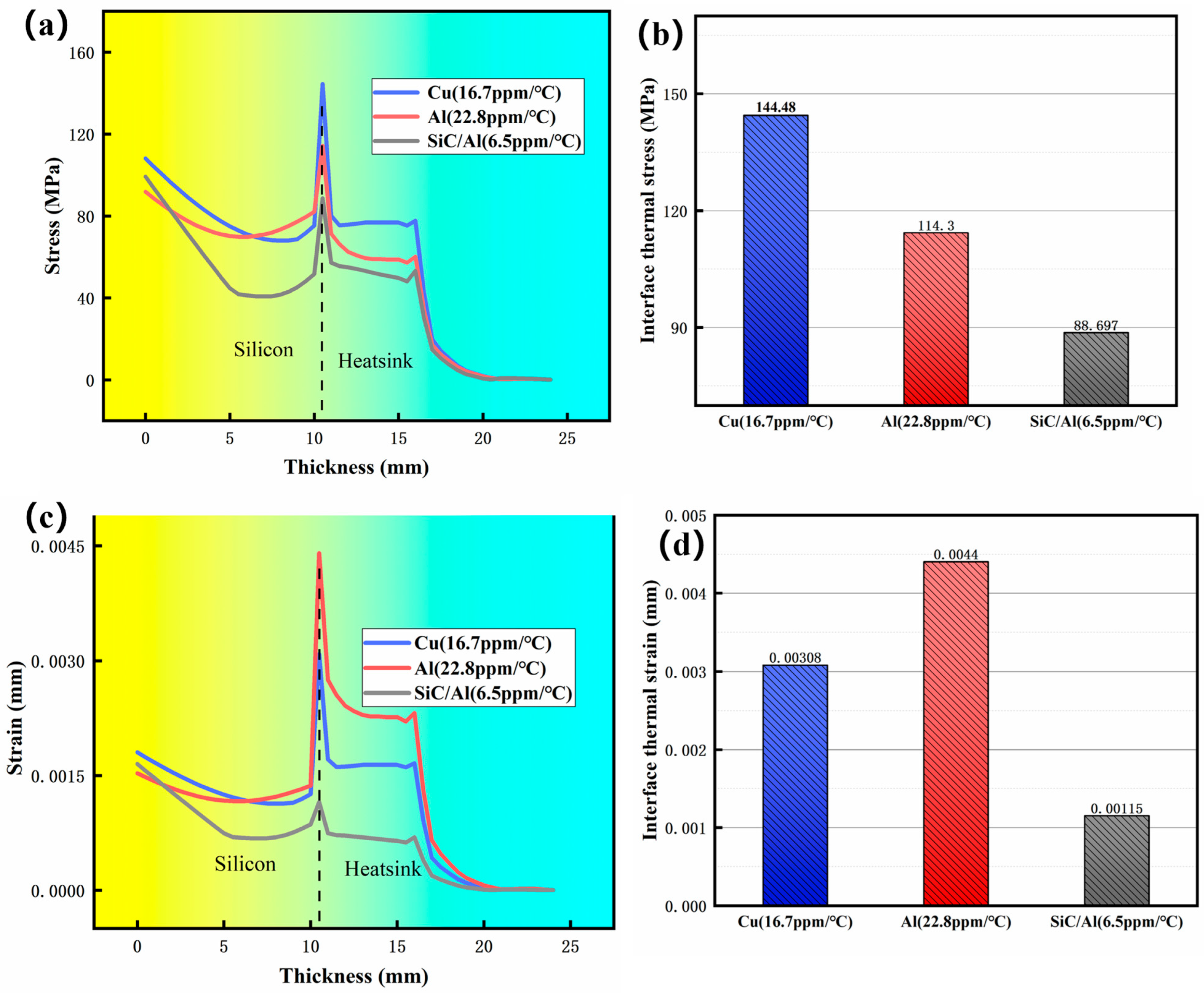
Figure 6 depicts the distribution of radial stress-strain in different homogeneous materials (Cu, Al, and SiC/Al composite). A sharp stress concentration is observed at the chip-heatsink interface across all materials. Notably, the Cu heatsink exhibits the highest peak radial stress (144.48 MPa), followed by Al (114.3 MPa) and the SiC/Al composite (88 MPa). Correspondingly, Figure 6c,d illustrates that the SiC/Al composite demonstrates a significantly reduced interfacial strain (0.00115 mm) compared to Cu and Al. These results underscore the critical importance of minimizing interfacial stress concentrations, which arise from CTE mismatch, to mitigate detrimental mechanical strain in microelectronic packaging.
(3)
Warping Deformation Mechanisms
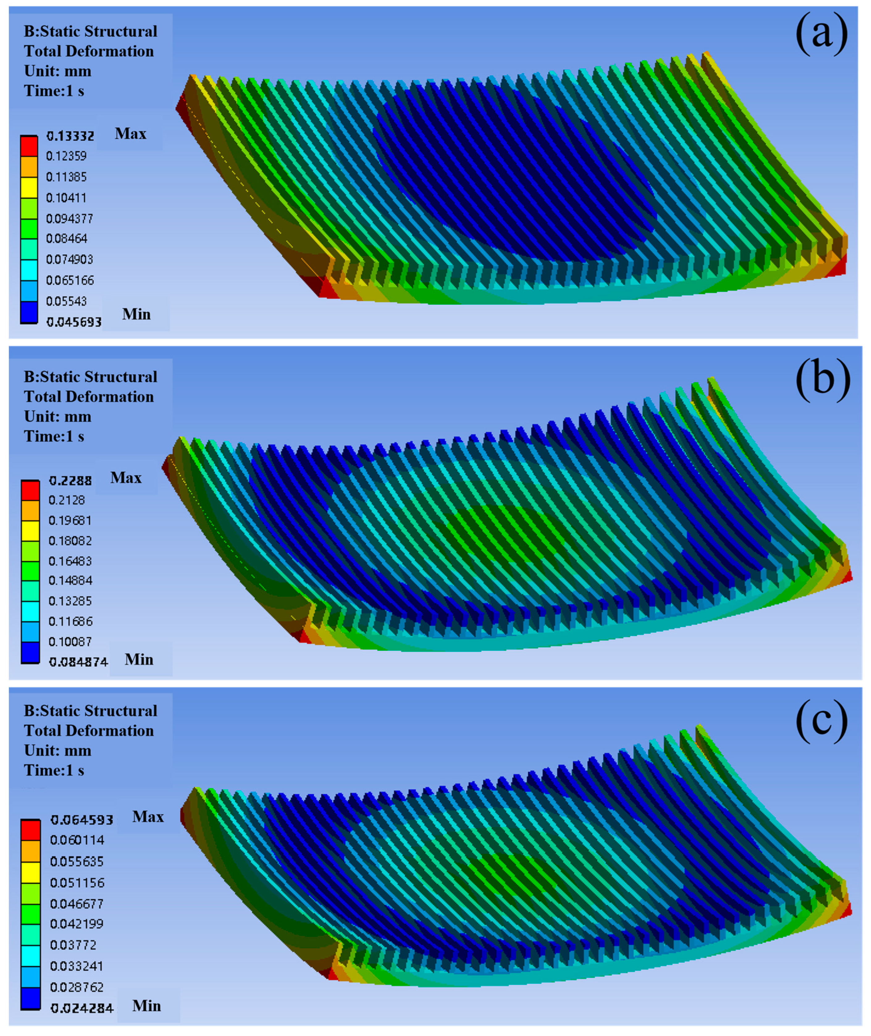
Unconstrained warping simulations (Figure 7) quantify deformation disparities among materials. Cu’s high CTE induces severe edge warping (0.133 mm), while Al’s plasticity amplifies deformation to 0.229 mm—exceeding typical PCB tolerance limits [16,17]. The SiC/Al composite reduces maximum warping by 71.6% (0.065 mm vs. Cu), aligning with its stress reduction trend. This deformation asymmetry arises from differential thermal expansion: the chip side (high CTE) experiences tensile stress, while the ambient side (low CTE) undergoes compression, creating a bending moment that peaks at free edges (Figure 7a–c). These results underscore the inadequacy of homogeneous materials for high-power applications, where warping exceeding 0.1 mm correlates with a 60% increase in solder joint failure rates.

3.2. Performance Enhancement via Gradient SiC/Al Composites

(1)
Axial Stress–Strain Optimization
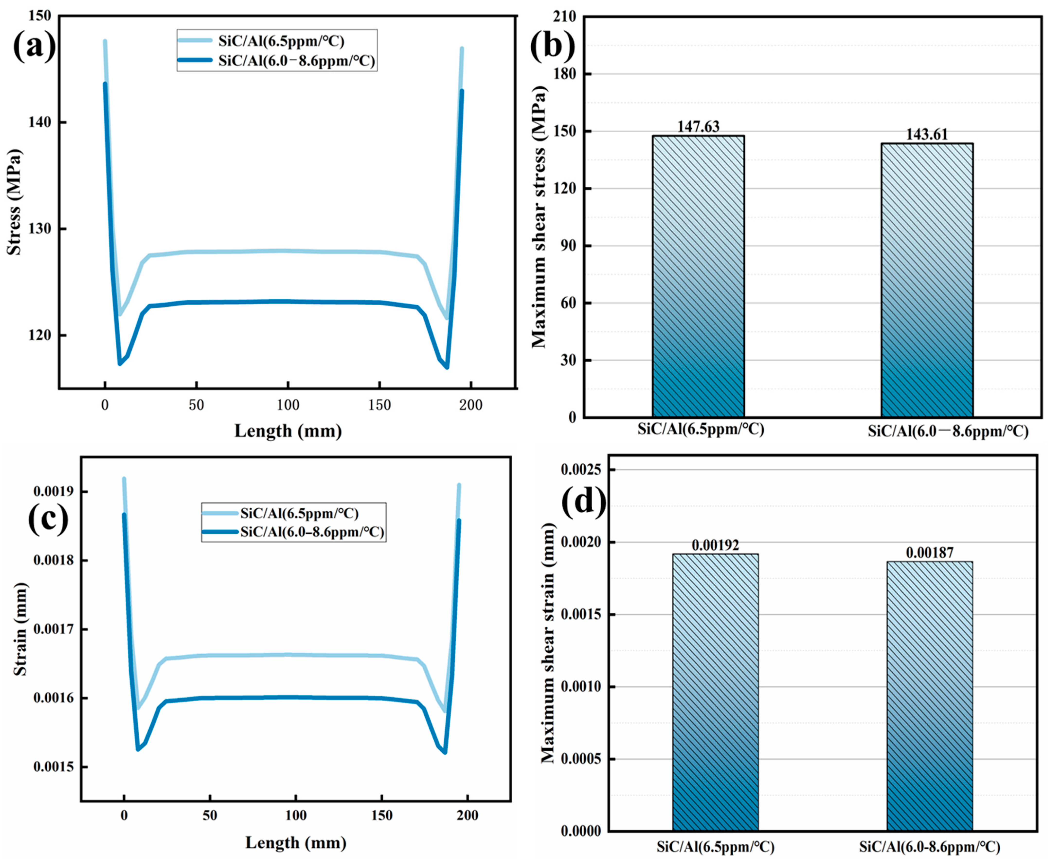
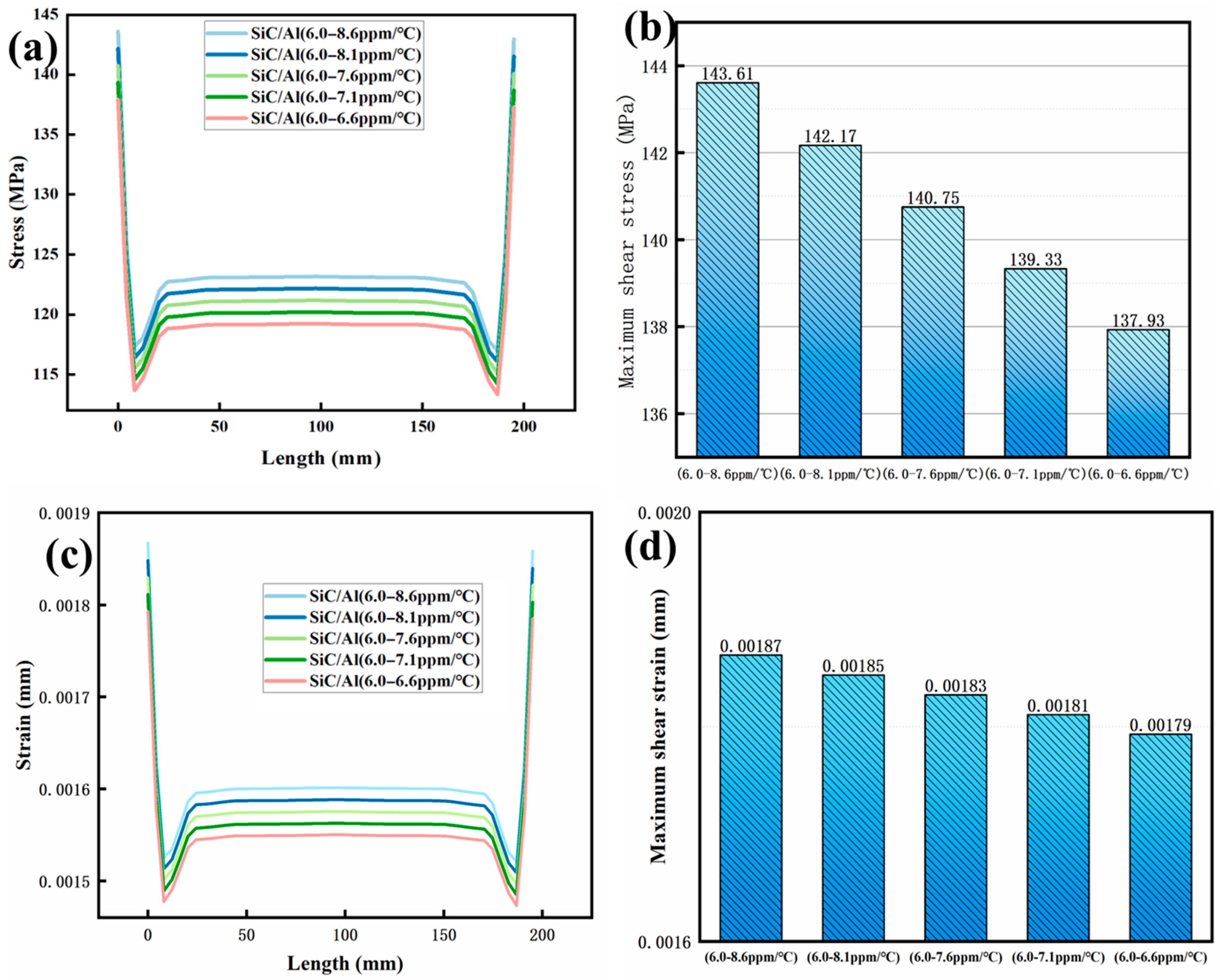
The gradient SiC/Al composite demonstrates superior thermomechanical resilience compared to its homogeneous counterparts. As shown in Figure 8, under a chip temperature of 200 °C, the maximum axial stress in the gradient material is reduced by 42.5% (137.93 MPa vs. 239.95 MPa for Cu), with strain limited to 0.001793 mm—a 71.3% reduction compared to Al (0.00612 mm). This improvement stems from the progressive CTE transition (6.5–9.0 ppm/°C), which eliminates abrupt interfacial strain discontinuities observed in homogeneous materials (Figure 6a). The stress distribution in the gradient structure (Figure 9) shows a smooth decay from the chip interface (137.93 MPa) to the ambient side (82.4 MPa), contrasting sharply with Cu’s edge-dominated stress concentration (239.95 MPa at corners).
(2)
Warping Deformation Optimization
Unconstrained thermal cycling simulations reveal the gradient materials’ exceptional warping resistance. As depicted in Figure 10, optimizing the CTE gradient from uniform (6.5 ppm/°C) to a 6.5–9.0 ppm/°C profile reduces maximum warping by 52% (0.065 mm vs. 0.133 mm for Cu). This deformation suppression correlates with a 28% reduction in interfacial shear stress (88 MPa vs. 144.48 MPa for Cu), critical for preventing solder joint fatigue in high-density packaging. The warping asymmetry—peaking at free edges (0.065 mm) and minimizing at the center (0.024 mm)—is mitigated by the gradient’s adaptive thermal expansion, balancing tensile and compressive strains across layers (Figure 10f).
(3)
Thermal Expansion Gradient Engineering
The strategic engineering of thermal expansion coefficient gradients is central to optimizing the thermomechanical performance of the SiC/Al composites. As demonstrated in Figure 10, parametric analysis of the CTE gradients (6.5–9.0 ppm/°C) reveals critical relationships between gradient design and material behavior under thermal cycling. When transitioning from a uniform CTE profile (6.5 ppm/°C, Figure 10a) to a progressive gradient (6.5–9.0 ppm/°C, Figure 10f), the maximum warping deformation decreases by 52% (0.133 mm → 0.065 mm), while the peak interfacial shear stress is reduced by 28% (144.48 MPa → 88 MPa). This enhancement is attributed to the adaptive thermal expansion matching mechanism, which eliminates abrupt strain discontinuities and redistributes thermal stress across gradient layers.
The relationship between the CTE gradient steepness and thermomechanical performance follows a nonlinear trend. For gradients steeper than 8.5 ppm/°C (Figure 10f), localized stress concentrations increase by 15% at layer interfaces due to abrupt CTE transitions. This phenomenon is governed by the strain compatibility equation:
ϵ i n t e r f a c e = α 1 T α 2 T 1 + ν
where α 1 and α 2 are the CTEs of adjacent layers, and ν is Poisson’s ratio. Conversely, gradients shallower than 7.5 ppm/°C (Figure 10c) exhibit 12% lower warping suppression efficiency, underscoring the necessity of balancing gradient steepness with stress dispersion. The nonlinear relationship between CTE gradient steepness and stress concentration can be empirically expressed as
σ p e a k = 88 + 12.5 α 8.5 2
where α is the CTE difference between adjacent layers. This quadratic trend highlights the necessity of balancing gradient design to avoid interfacial dislocations (Figure 10f). Microscopically, the gradient structure redistributes dislocations by relaxing strain gradients, as evidenced by the dislocation density (ρ) in Equation (4), thereby suppressing crack initiation at interfaces.
(4)
Integrated Analysis and Validation
Through a multiphysics coupling model (Figure 2), this study quantifies the thermomechanical co-optimization mechanism of gradient materials. The synergistic effect of thermal resistance reduction and stress suppression (42.5%) can be attributed to the adaptive thermal expansion matching of the gradient structure, and its mechanism can be explained by the dislocation density model:
σ = σ 0 + α G b ρ
σ represents the yield stress of the material and σ 0   represents the initial stress in the dislocation-free state. α is a dimensionless constant related to the material type and dislocation interaction. In this paper, the dislocation distribution is optimized through gradient design to reduce the effective α value, thereby reducing stress. G is the shear modulus. b represents the Burgers vector. ρ represents the dislocation density; the gradient structure reduces ρ through strain gradient relaxation. The gradient SiC/Al composite disperses thermal stress concentrations through continuously varying CTE (6.5–9.0 ppm/°C), reducing local plastic deformation, thereby inhibiting dislocation multiplication (such as dislocation pile-up and entanglement), leading to a decrease in ρ. The introduction of SiC particles increases the matrix stiffness, while the gradient distribution avoids abrupt changes in b (such as interfacial dislocations in homogeneous materials), further suppressing stress elevation. The model indicates that through the optimization of α and ρ via gradient design, directional control of thermomechanical properties can be achieved, providing a theoretical basis for subsequent multi-objective optimizations, such as the synergy of thermal conductivity and CTE.

4. Conclusions

This study reveals the significant advantages of gradient SiC/Al composite materials under thermomechanical coupling by establishing a stress–strain analysis model that integrates temperature fields with thermal expansion coefficient distributions. Compared to traditional homogeneous materials (such as Cu and Al), the gradient design, through an adaptive thermal expansion matching mechanism, reduces peak stress and decreases the maximum warping by 52%, while also increasing the maximum operating temperature of the heat sink. This breakthrough achievement demonstrates important application value in high-power electronic devices, significantly delaying thermal failure by suppressing the temperature rise in key components. Although gradient materials have an advantage in thermomechanical reliability, their industrialization still needs to overcome challenges related to interlayer bonding strength and cost-effectiveness. Future research should focus on multi-objective optimization (synergistic control of thermal conductivity and thermal expansion), thermal shock experimental validation, and AI-driven inverse design to further expand their potential in extreme environment electronic systems, providing theoretical support and an engineering pathway for the next generation of high-reliability packaging technologies.

Author Contributions

Conceptualization, J.Z. (Junfeng Zhao); methodology, J.Z. (Junfeng Zhao) and K.L.; software, J.Z. (Junfeng Zhao) and Zhang: J.Z. (Junliang Zhang); validation, J.Z. (Junfeng Zhao) and H.S. formal analysis, J.Z. (Junfeng Zhao) and Y.Z.; investigation, J.Z. (Junfeng Zhao) and K.L.; data curation, J.Z. (Junfeng Zhao) and Q.Z.; writing—original draft preparation, Zhao: J.Z. (Junfeng Zhao) and Zhang: J.Z. (Junliang Zhang); writing—review and editing, J.Z. (Junfeng Zhao) and K.L.; visualization, J.Z. (Junfeng Zhao) and H.M.; supervision, J.Z. (Junfeng Zhao) and C.W.; project administration, J.Z. (Junfeng Zhao) and W.G.; funding acquisition, J.Z. (Junfeng Zhao) and W.G. All authors have read and agreed to the published version of the manuscript.

Funding

This research was funded by the Featured Innovation Project of General Colleges and Universities in Guangdong Province grant number (2022KTSCX137).

Institutional Review Board Statement

Not applicable.

Informed Consent Statement

Not applicable.

Data Availability Statement

The original contributions presented in this study are included in the article. Further inquiries can be directed to the corresponding authors.

Conflicts of Interest

The authors declare no conflict of interest.

References

  1. Das Sharma, D.; Pasdast, G.; Tiagaraj, S.; Aygün, K. High-performance, power-efficient three-dimensional system-in-package designs with universal chiplet interconnect express. Nat. Electron. 2024, 7, 244–254. [Google Scholar] [CrossRef]
  2. Wen, Y.; Chen, C.; Ye, Y.; Xue, Z.; Liu, H.; Zhou, X.; Zhang, Y.; Li, D.; Xie, X.; Mai, Y.W. Advances on thermally conductive epoxy-based composites as electronic packaging underfill materials—A review. Adv. Mater. 2022, 34, 2201023. [Google Scholar] [CrossRef] [PubMed]
  3. Pathak, S.K.; Sharma, P.O.; Goel, V.; Bhattacharyya, S.; Aybar, H.Ş.; Meyer, J.P. A detailed review on the performance of photovoltaic/thermal system using various cooling methods. Sustain. Energy Technol. Assess. 2022, 51, 101844. [Google Scholar] [CrossRef]
  4. Liao, K.; Zhong, Y.; Du, Z.; Liu, G.; Li, C.; Wu, X.; Deng, C.; Lu, C.; Wang, X.; Chan, C.T. On-chip integrated exceptional surface microlaser. Sci. Adv. 2023, 9, eadf3470. [Google Scholar] [CrossRef] [PubMed]
  5. Moore, A.L.; Shi, L. Emerging challenges and materials for thermal management of electronics. Mater. Today 2014, 17, 163–174. [Google Scholar] [CrossRef]
  6. Kukkapalli, V.K.; Kim, S.; Thomas, S.A. Thermal Management Techniques in Metal Hydrides for Hydrogen Storage Applications: A Review. Energies 2023, 16, 3444. [Google Scholar] [CrossRef]
  7. Kieback, B.; Neubrand, A.; Riedel, H. Processing techniques for functionally graded materials. Mater. Sci. Eng. A 2003, 362, 81–106. [Google Scholar] [CrossRef]
  8. Sun, J.; Jing, Q.; Lei, L.; Zhang, J. Compositional gradient affects the residual stress distribution in Si3N4/SiC functionally graded materials. Ceram. Int. 2023, 49, 19281–19289. [Google Scholar] [CrossRef]
  9. Zhang, C.; Qu, Z.; Fang, X.; Feng, X.; Hwang, K.-C. Digital gradient sensing method to evaluate thermal stress at elevated temperatures. Exp. Mech. 2016, 56, 1123–1132. [Google Scholar] [CrossRef]
  10. Yang, K.; Jiang, G.-H.; Qu, Q.; Peng, H.-F.; Gao, X.-W. A new modified conjugate gradient method to identify thermal conductivity of transient non-homogeneous problems based on radial integration boundary element method. Int. J. Heat Mass Transf. 2019, 133, 669–676. [Google Scholar] [CrossRef]
  11. Chen, T.-C.; Lin, W.-J.; Chen, D.-L. Effect of temperature gradient on simultaneously experimental determination of thermal expansion coefficients and elastic modulus of thin film materials. J. Appl. Phys. 2004, 96, 3800–3806. [Google Scholar] [CrossRef]
  12. Lutz, M.P.; Zimmerman, R.W. Thermal stresses and effective thermal expansion coefficient of a functionally gradient sphere. J. Therm. Stress. 1996, 19, 39–54. [Google Scholar] [CrossRef]
  13. Zhao, L.-H.; Wang, L.; Jin, Y.-F.; Ren, J.-W.; Wang, Z.; Jia, L.-C. Simultaneously improved thermal conductivity and mechanical properties of boron nitride nanosheets/aramid nanofiber films by constructing multilayer gradient structure. Compos. Part B Eng. 2022, 229, 109454. [Google Scholar] [CrossRef]
  14. Zhao, J.; Yang, Z.; Li, Q.; Wang, L. Fabrication of SiC/Al functionally graded materials via filtration extrusion. Adv. Eng. Mater. 2023, 25, 2300384. [Google Scholar] [CrossRef]
  15. Gao, Y.; Yi, J.; Lee, P.; Lindley, T. A micro-cell model of the effect of microstructure and defects on fatigue resistance in cast aluminum alloys. Acta Mater. 2004, 52, 5435–5449. [Google Scholar] [CrossRef]
  16. Xia, W.; Xiao, M.; Chen, Y.; Wu, F.; Liu, Z.; Fu, H. Thermal warpage analysis of PBGA mounted on PCB during reflow process by FEM and experimental measurement. Solder. Surf. Mt. Technol. 2014, 26, 162–171. [Google Scholar] [CrossRef]
  17. Chung, S.; Heo, G.; Kwak, J.; Oh, S.; Lee, Y.; Kang, C.; Lee, T. Development of PCB design guide and PCB deformation simulation tool for slim PCB quality and reliability. In Proceedings of the 2013 IEEE 63rd Electronic Components and Technology Conference, Las Vegas, NV, USA, 28–31 May 2013; IEEE: Piscataway, NJ, USA, 2013; pp. 2157–2162. [Google Scholar]
Figure 1. Schematic diagram of gradient SiC/Al material structure.
Materials 18 03788 g001
Figure 2. (a) Thermal simulation model; (b) mesh of simulation model; (c) axial direction; (d) radial direction.
Materials 18 03788 g002
Figure 3. Temperature distributions and total heat flux distributions of different heat sink materials: (a,b) Cu; (c,d) Al; (e,f) SiC/Al.
Materials 18 03788 g003
Figure 4. Stress–strain of different packaging materials as temperature increases: (a) stress; (b) strain.
Materials 18 03788 g004
Figure 5. Distribution of axial stress–strain in different packaging materials at 200 °C: (a,b) stress; (c,d) strain.
Materials 18 03788 g005
Figure 6. Distribution of radial stress–strain in different homogeneous materials at 200 °C: (a,b) stress; (c,d) strain.
Materials 18 03788 g006
Figure 7. Contour plots of warping deformation distribution for different packaging materials: (a) Cu; (b) Al; (c) SiC/Al (unit: mm).
Materials 18 03788 g007
Figure 8. Comparison of stress–strain between gradient and homogeneous structures of SiC/Al material: (a,b) stress; (c,d) strain.
Materials 18 03788 g008
Figure 9. Distribution of axial thermal stress and strain for different gradient SiC/Al structures: (a,b) stress; (c,d) strain.
Materials 18 03788 g009
Figure 10. Optimization of thermal expansion coefficient for warping of gradient SiC/Al material (without fixed constraints) (ppm/°C): (a) 6.5–6.5; (b) 6.5–7.0; (c) 6.5–7.5; (d) 6.5–8.0; (e) 6.5–8.5; (f) 6.5–9.0.
Materials 18 03788 g010
Table 1. Mechanical characteristics of the material utilized for simulation.
MaterialSiAlCuSiC/Al
Properties
Young’s modulus
E (GPa)
15069126200
Poisson’s ratio (μ)0.250.330.3450.3
Density
(kg/m3)
2330271389422990
thermal expansion coefficient (ppm/°C)2.522.816.76.5
thermal conductivity (W/(m·°C))148155.3396.7160
specific heat capacity (J/(kg·°C))712915.7383.3951
Table 2. Steady-state thermal analysis results.
MaterialMax Temperature (°C)Min Temperature (°C)Heat Flux (W/mm2)
Cu92.18875.3981.0637
Al98.99164.9230.92556
SiC/Al98.69265.3440.93112
Disclaimer/Publisher’s Note: The statements, opinions and data contained in all publications are solely those of the individual author(s) and contributor(s) and not of MDPI and/or the editor(s). MDPI and/or the editor(s) disclaim responsibility for any injury to people or property resulting from any ideas, methods, instructions or products referred to in the content.