


Microstructural Characterisation of Bi-Ag-Ti Solder Alloy and Evaluation of Wettability on Ceramic and Composite Substrates Joined via Indirect Electron Beam Heating in Vacuum


 , , , and
Abstract
1. Introduction
2. Materials and Methods
- Ceramic Al2O3 and SiC substrates in the form of discs, Ø 15 × 3 mm;
- Ni-SiC substrates in a rectangular shape, 10 × 10 mm, with a thickness of 3 mm;
- Round SiC and Ni-SiC substrates, Ø 15 × 3 mm, were used for the fabrication of joints intended for microscopic analysis.
3. Results
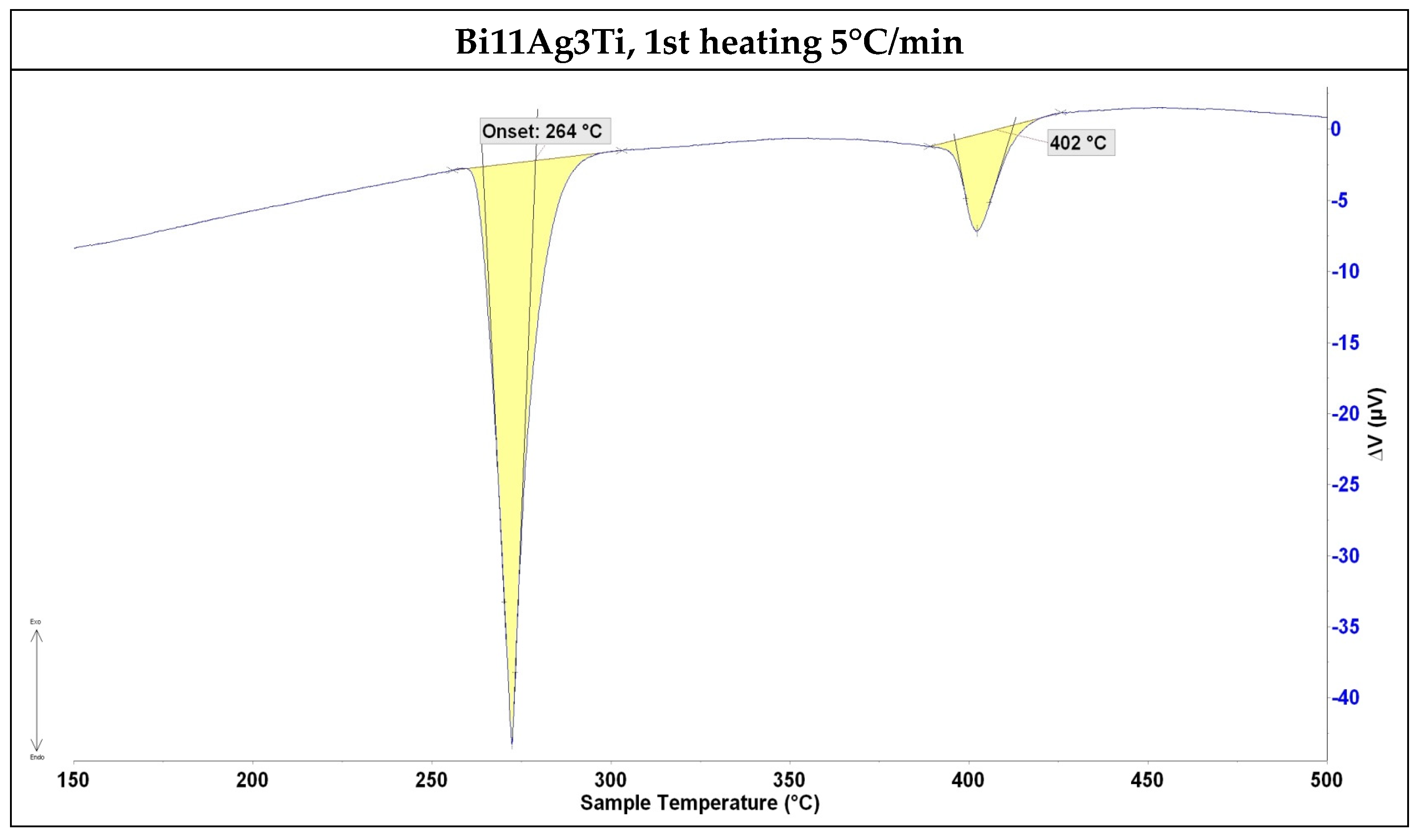
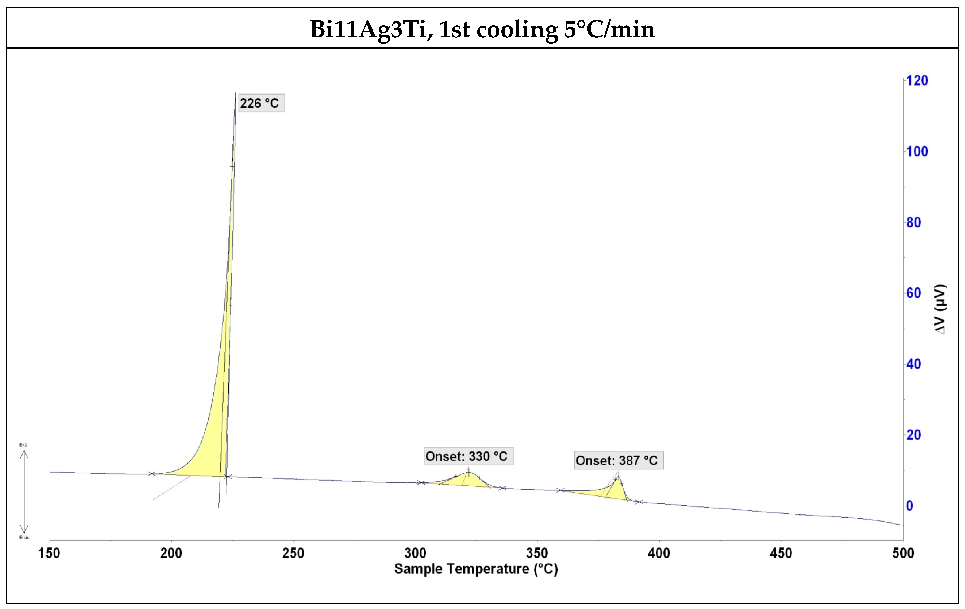
3.1. DTA Analysis
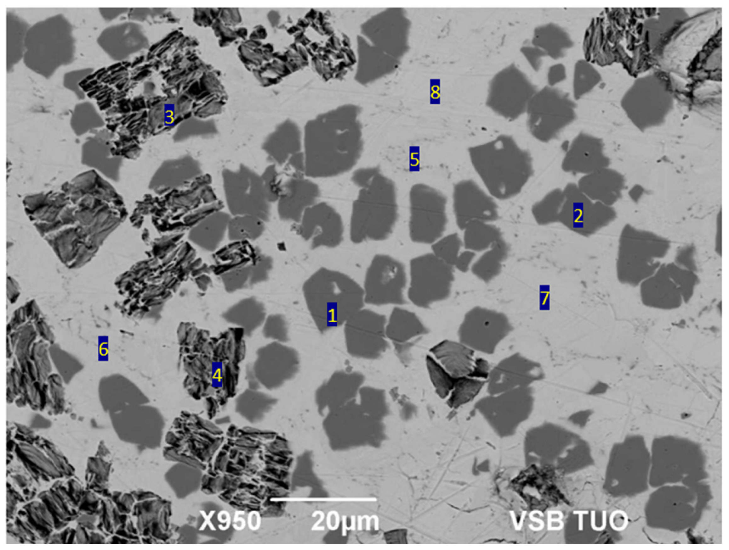
3.2. Microstructure of Soldering Alloy
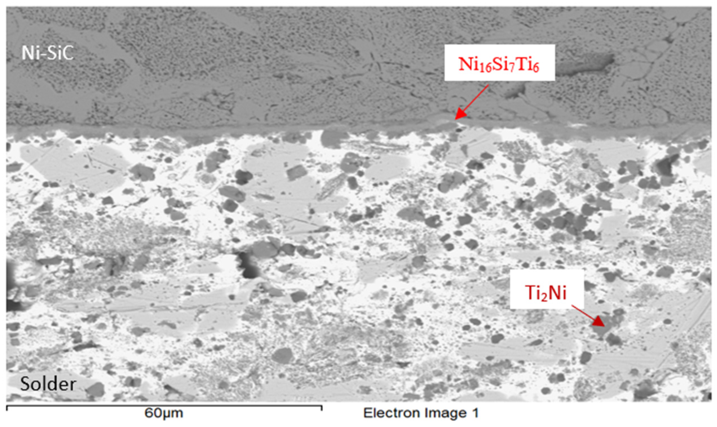
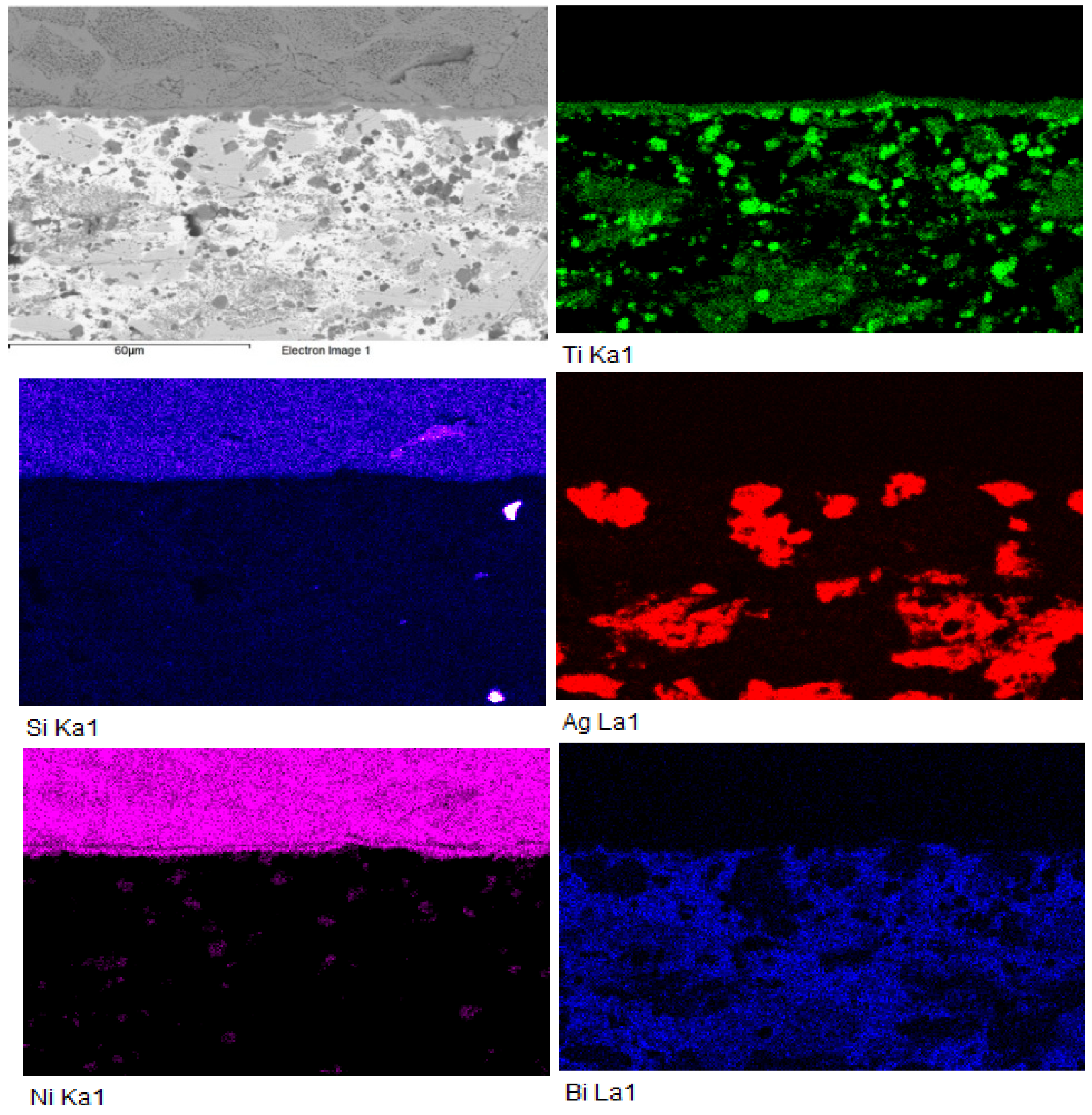
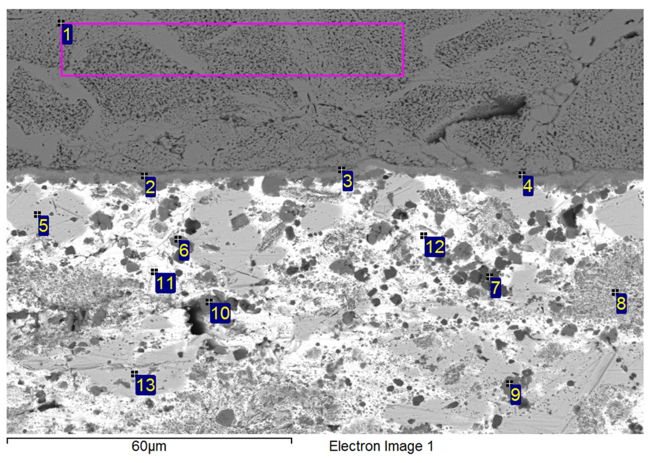
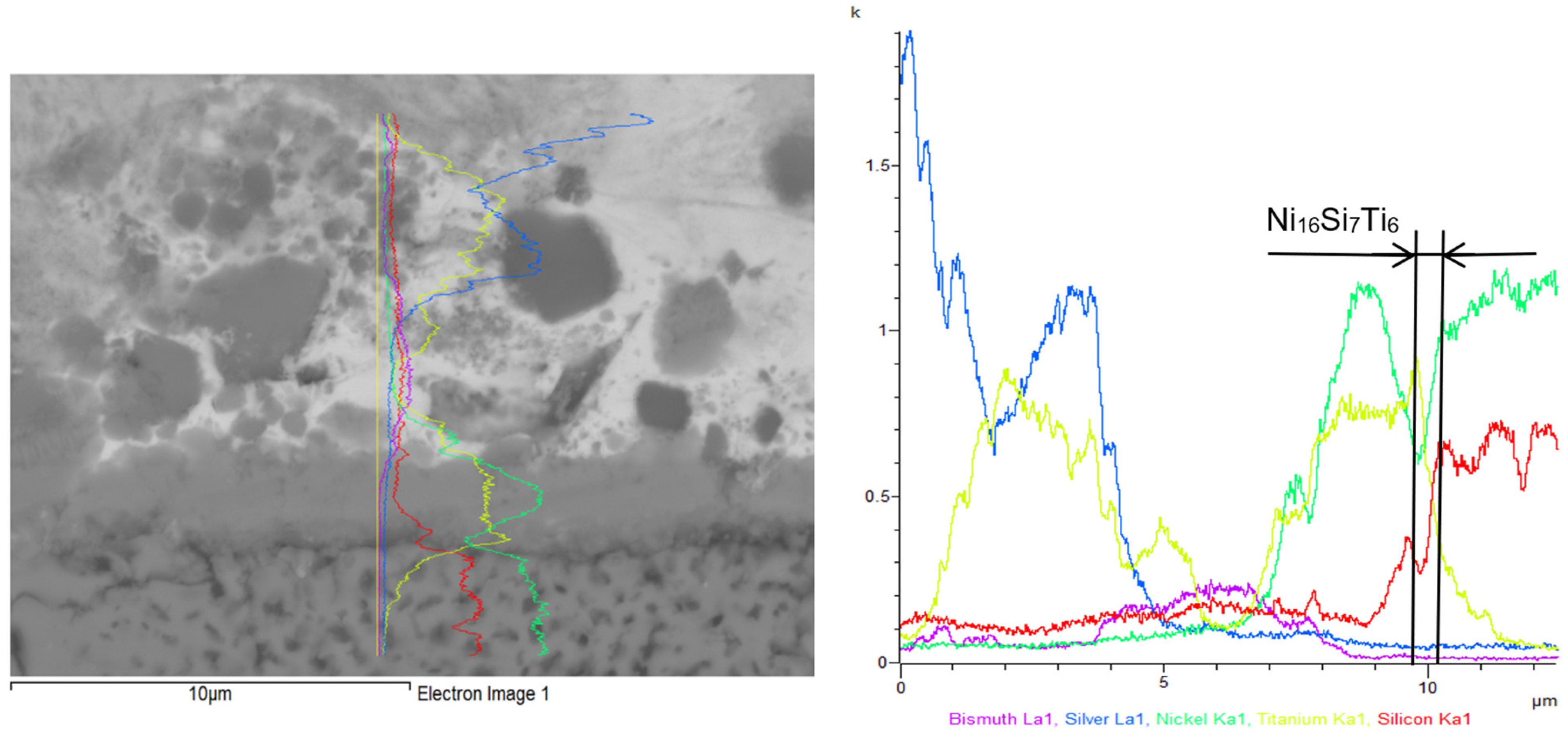
3.3. Analysis of Transition Zone in Ni-SiC/Bi11Ag3Ti Joint
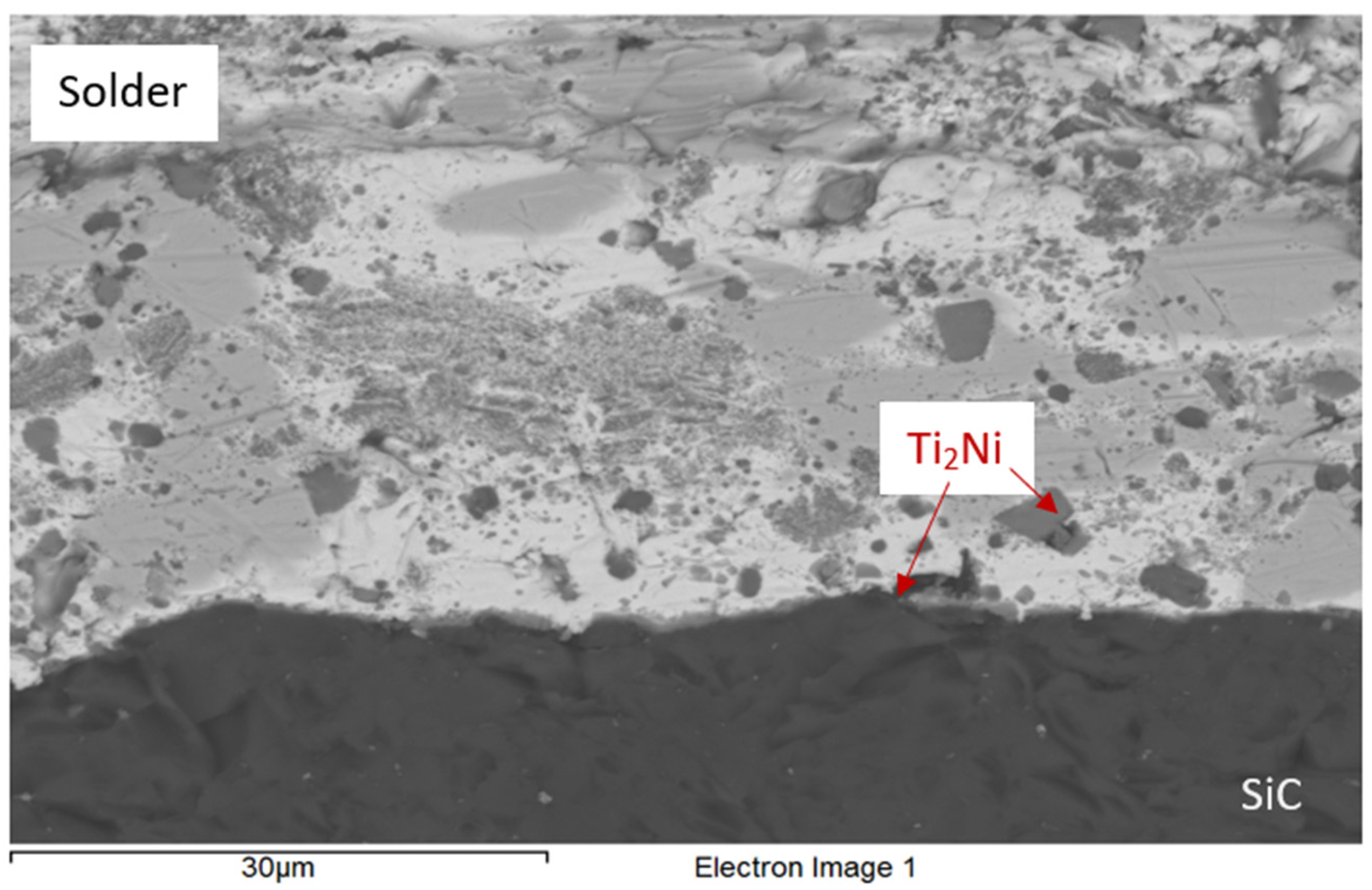
3.4. Analysis of Transition Zone in SiC/Bi11Ag3Ti Joint
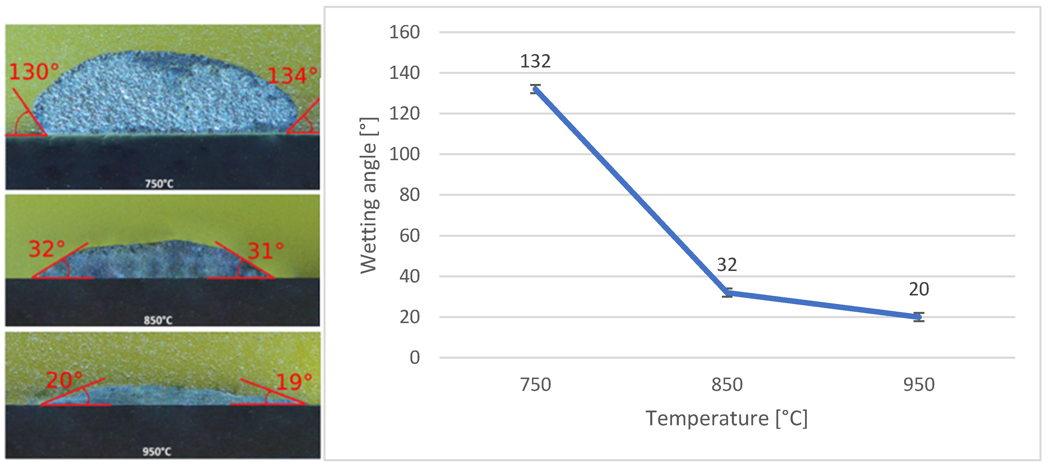
3.5. Wettability of SiC and Ni-SiC Substrates
3.6. Shear Strength of Soldered Joints
4. Conclusions
- The solder alloy specimen was analysed using DTA at a heating rate of 5 °C/min up to 500 °C. A peak temperature of 264 °C was observed, indicating a eutectic transformation and the formation of silver lamellae within the bismuth matrix. A second peak at 402 °C corresponded to the melting point of the soldering alloy, consistent with the binary Ag-Bi phase diagram.
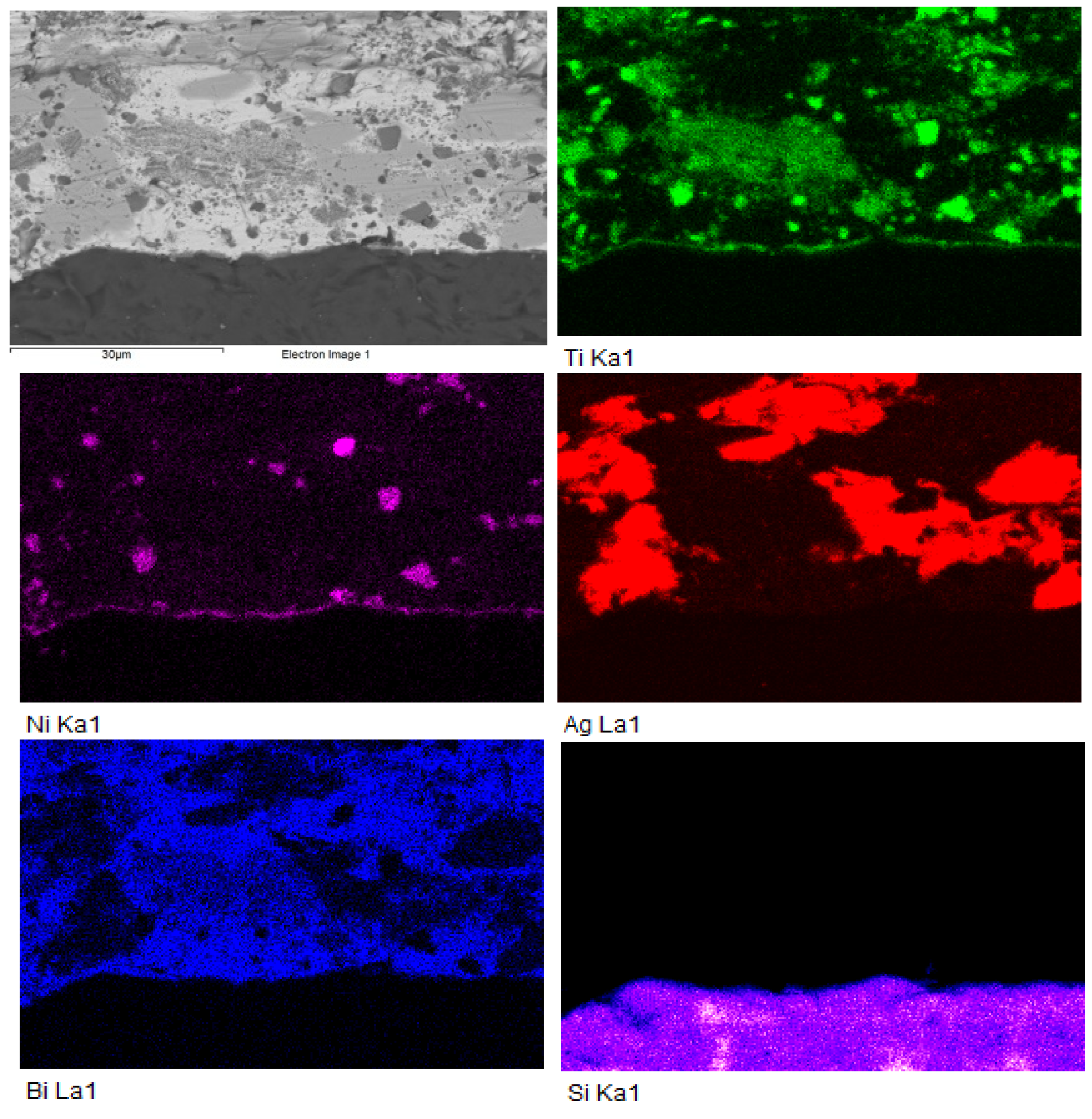
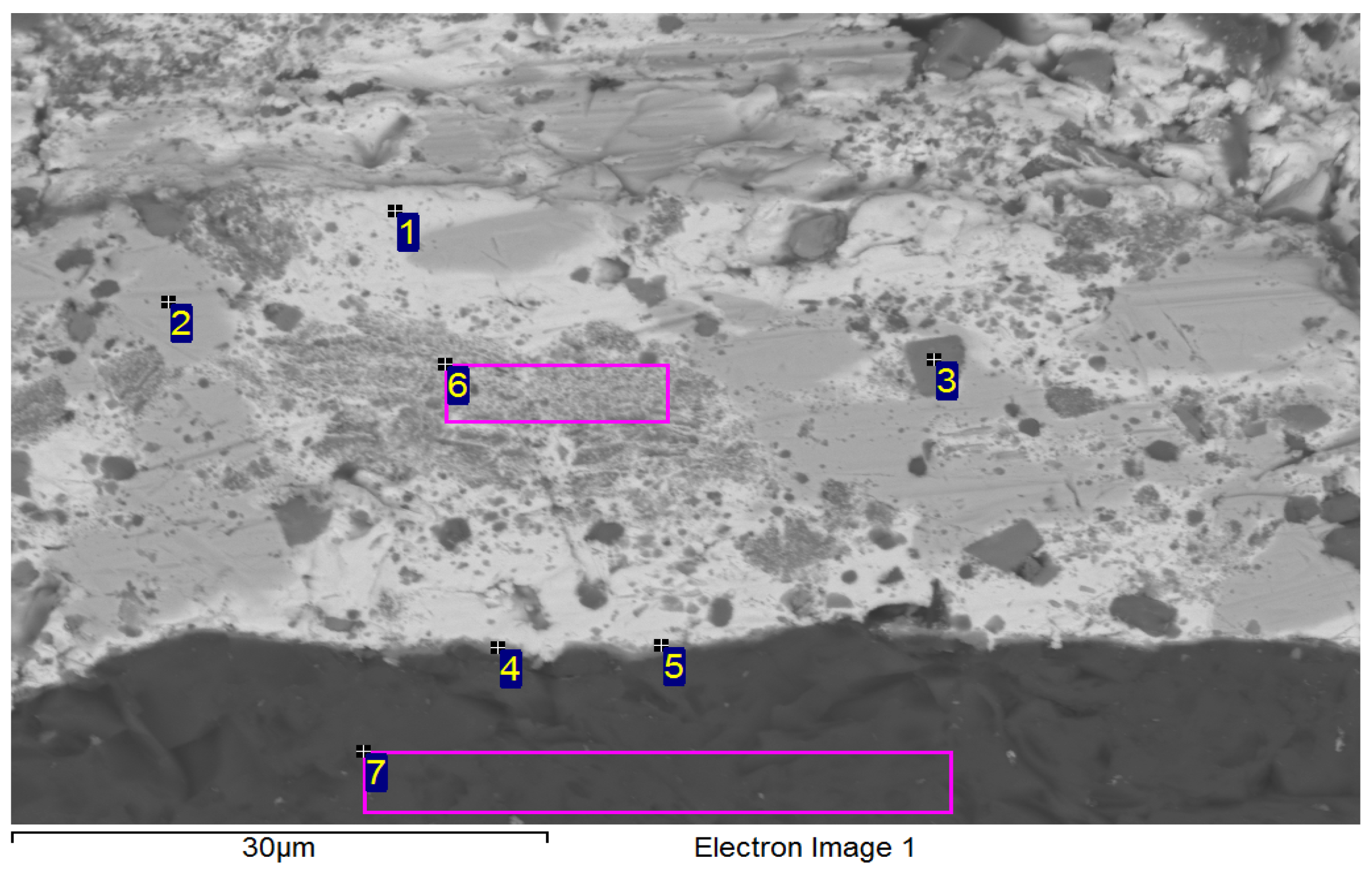
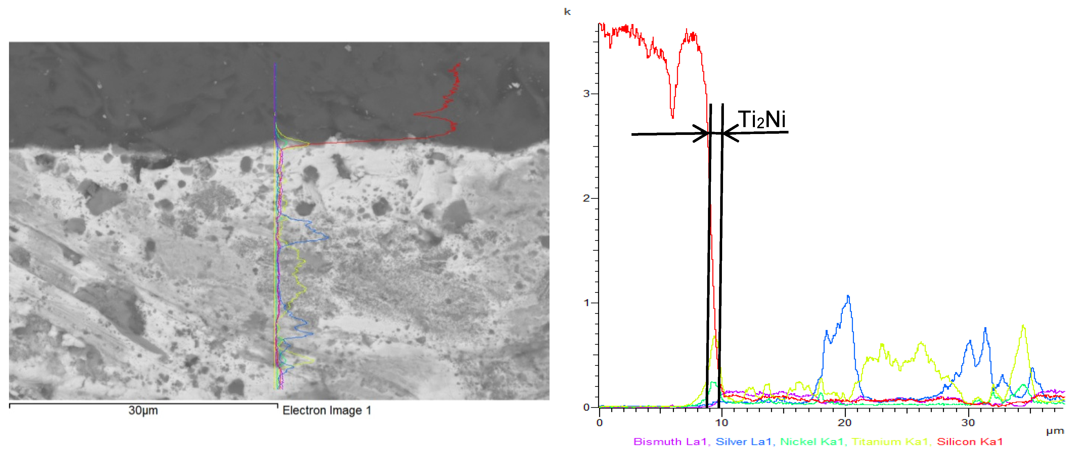
- SEM/EDX analysis of the Ni-SiC/Bi11Ag3Ti/SiC joint boundary confirmed the diffusion of Ni and Si throughout the joint. These elements formed the intermetallic phase Ni16Si7Ti6, resulting in the formation of a reaction layer at the Ni-SiC/Bi11Ag3Ti interface. Ni was also detected at the boundary with the ceramic substrate. Ti at the joint boundary facilitated the wetting of the parent materials, leading to the formation of intermetallic Ti2Ni phases within the solder, along with a solid solution of Ag containing partially dissolved Bi. The reaction layer between the Ni-SiC and the solder measured approximately 5 μm in thickness.
- At the SiC/solder interface, a reaction layer approximately 3 μm thick was formed, containing the Ti2Ni phase. This layer indicated interaction between Ni from the upper substrate and Ti in the solder. Ti thus fulfilled its role as an active element, promoting the wetting of the parent metals and forming the observed phases at the joint boundary. A solid solution of silver was also present, with partially dissolved bismuth and the formation of a mixture of Ti8Bi9 and Ti2Bi phases.
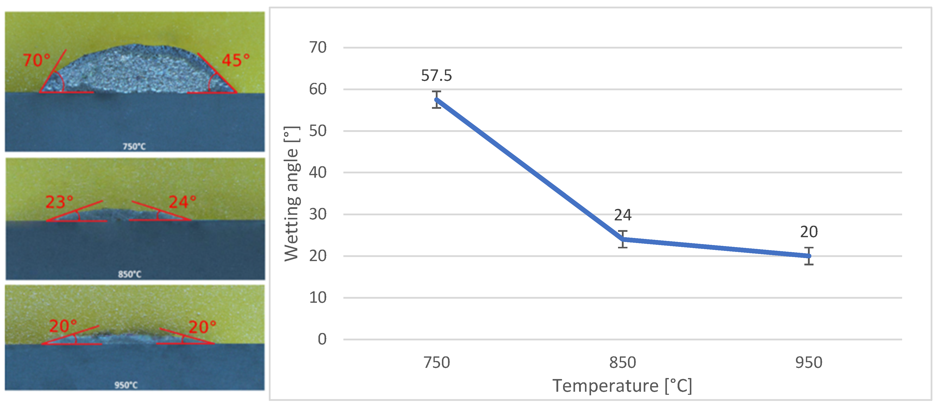
- The wettability of the Bi11Ag3Ti solder on Ni-SiC and SiC substrates was studied at working temperatures of 750 °C, 850 °C, and 950 °C. The results indicated that both substrates achieved a wetting angle of 20° at 950 °C, which is considered indicative of good wettability. This finding also suggested that 950 °C was the most suitable temperature for use with both substrates. The measurements further showed that varying the working temperatures led to different wetting angles. This conclusion was based on the comparison of average values obtained from the tested specimens, with a clear trend of improved wettability at higher temperatures. For the Ni-SiC substrate, a working temperature of 750 °C was unacceptable.
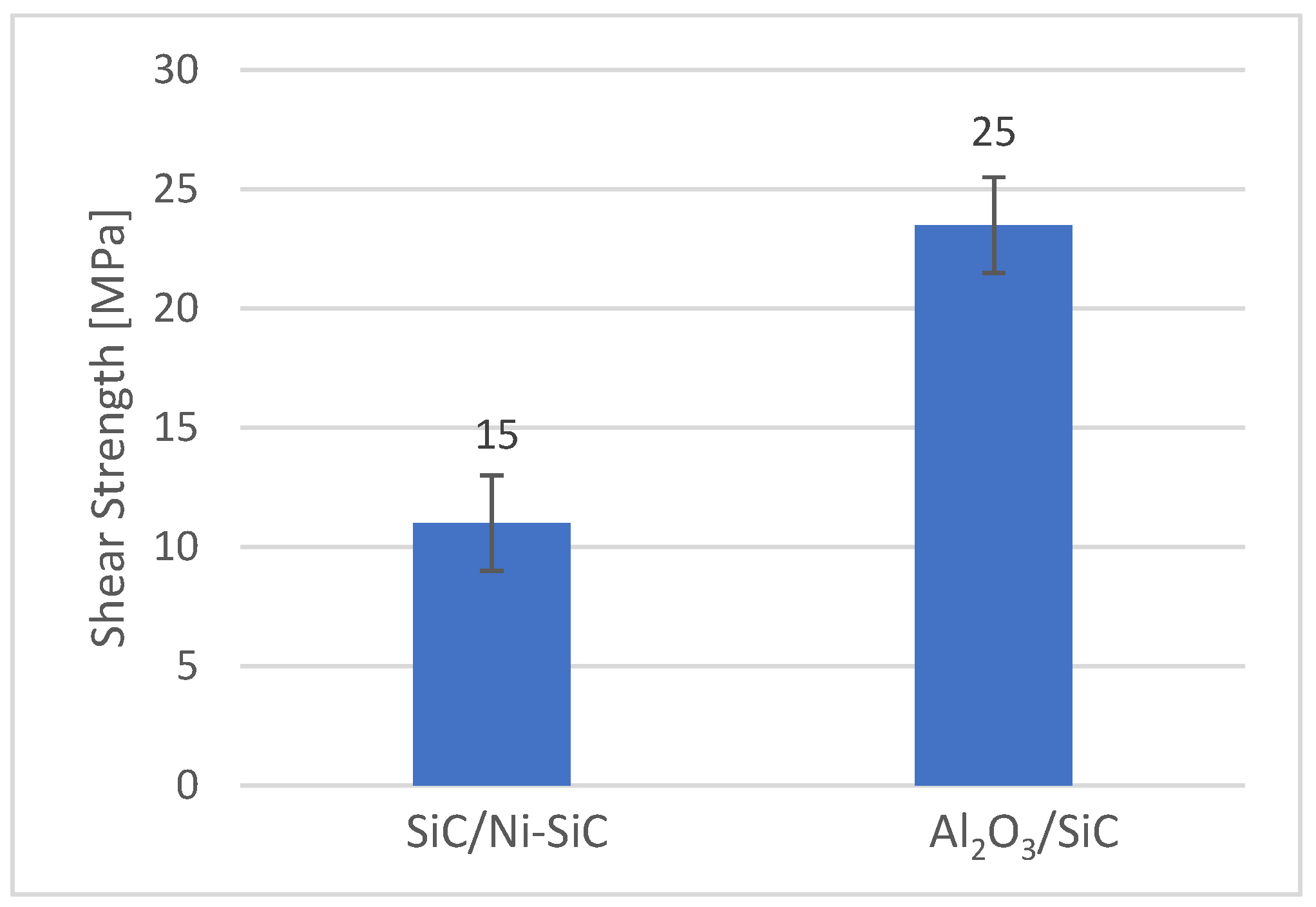
- The mechanical shear strength test of the joint revealed a value of 15 MPa for the SiC/Bi11Ag3Ti/Ni-SiC configuration. For comparison, an Al2O3/ Bi11Ag3Ti/Ni-SiC joint was also fabricated, which achieved a shear strength of 25 MPa.
- The Bi11Ag3Ti solder alloy demonstrated a competitive performance compared to other Bi–Ag–Me systems reported in the literature. Its melting temperature range (262–405 °C), shear strength (15–25 MPa), and contact angles (20–130°) are comparable to values obtained for Bi–Ag–Ti and Bi–Ag–Mg solders. The presence of titanium significantly contributes to wetting behaviour and joint strength by promoting the formation of interfacial reaction layers on ceramic substrates. Based on these comparisons, the Bi11Ag3Ti solder demonstrates competitive performance among Bi–Ag–Me solder systems, offering a balanced combination of a low melting temperature, sufficient mechanical strength, and effective wetting on ceramic and composite substrates. These characteristics underline its potential for applications in joining dissimilar materials, especially when active element-assisted wetting is required.
Author Contributions
Funding
Institutional Review Board Statement
Informed Consent Statement
Data Availability Statement
Acknowledgments
Conflicts of Interest
References
- Liu, Y.; Cui, W.; Ji, X. Bonding mechanism in ultrasonic-assisted soldering of ZrO2 and 304 stainless steel using micro-alloyed active solder alloy. Mater. Lett. 2022, 322, 132456. [Google Scholar] [CrossRef]
- Otiaba, K.C.; Bhatti, R.S.; Ekere, N.N. Finite element analysis of the effect of silver content for Sn-Ag-Cu alloy compositions on thermal cycling reliability of solder die attach. Eng. Fail. Anal. 2013, 28, 192–207. [Google Scholar] [CrossRef]
- Yang, Z.; Cheng, L.; Chen, S.; Zhang, Y. Active element Ti improves the Sn-based alloy filler/graphite soldering interface: A combined first-principles and experimental study. Mater. Sci. Semicond. Process. 2024, 177, 108390. [Google Scholar] [CrossRef]
- Asghari, M.; Beidokhti, B.; Mollazadeh Beidokhti, S. Effect of metallization method on properties of hybrid zirconia/Ti-6Al-4V joints. Mater. Chem. Phys. 2023, 296, 127212. [Google Scholar] [CrossRef]
- Li, Y.; Chen, C.H.; Yi, R.; Ouyang, Y. Review: Special brazing and soldering. J. Manuf. Process. 2020, 60, 608–635. [Google Scholar] [CrossRef]
- Wang, W.; Tsai, Y. Microstructural characterization and mechanical property of active soldering anodized 6061 Al alloy using Sn-3.5Ag-xTi active solders. Mater. Charact. 2012, 68, 42–48. [Google Scholar] [CrossRef]
- Chidambaram, V.; Hattel, J.; Hald, J. Design of lead-free candidate alloys for high-temperature soldering based on the Au-Sn system. Mater. Des. 2010, 31, 4638–4645. [Google Scholar] [CrossRef]
- Kroupa, A.; Andersson, D.; Hoo, N. Current problems and possible solutions in high-temperature lead-free soldering. J. Mater. Perform 2012, 21, 629–637. [Google Scholar] [CrossRef]
- Kolenak, R.; Kostolny, I.; Drapala, J.; Babincova, P.; Gogola, P. Characterization of Soldering Alloy Type Bi-Ag-Ti and the Study of Ultrasonic Soldering of Silicon and Copper. Metals 2021, 11, 624. [Google Scholar] [CrossRef]
- Negm, S.; Moghny, A.; Ahmad, S. Investigation of thermal and mechanical properties of Sn-Zn and Sn-Zn- Bi near-eutectic solder alloys. Results Mater. 2022, 15, 100316. [Google Scholar] [CrossRef]
- Silva, B.; Gouveia, G.; Cheung, N.; Garcia, A.; Spinelli, J. Analysis of extensive wetting angle vs. Cooling rate data in Bi-, Tn- and Sn, based solder alloys. Microelectron. Reliab. 2022, 135, 1144593. [Google Scholar] [CrossRef]
- Spinelli, J.; Silva, B.; Cheung, N.; Garcia, A. The use of a directional solidification technique to investigate the interrelationship of thermal parameters, microstructure and microhardness of Bi-Ag solder alloys. Mater. Charact. 2014, 95, 115–125. [Google Scholar] [CrossRef]
- Spinelli, J.; Silva, B.; Garcia, A. Microstructure, phases morphologies and hardness of Bi-Ag eutectic alloy for high temperature soldering applications. Mater. Des. 2014, 58, 482–490. [Google Scholar] [CrossRef]
- Yin, L.; Li, D.; Yao, Z.; Blackburn, A. Microstructures and properties of Bi10Ag high temperature solder doped with Cu element. Microelectron. Reliab. 2018, 80, 84–89. [Google Scholar] [CrossRef]
- Kim, B.; Lee, C.H.; Lee, D.; Kang, N. Effect of Sb addition on Bi-2.6Ag-0.1Cu solders for high-temperature applications. J. Alloys Compd. 2014, 592, 207–212. [Google Scholar] [CrossRef]
- Shalaby, R.M.; Allzeleh, M.M.; Kamal, M. Enhancement of melt-spun process Bi-Ag lead-free solder for high temperature applications. J. Mater. Sci. Mater. Electron. 2018, 29, 20554–20563. [Google Scholar] [CrossRef]
- Qu, W.; Zhou, S.; Zhuang, H. Effect of Ti content and Y additions on oxidation behaviour of SnAgTi solder and its application on dissimilar metals soldering. Mater. Des. 2015, 88, 737–742. [Google Scholar] [CrossRef]
- Yu, W.; Liu, S.; Liu, X.; Liu, M.; Shi, W. Interface reaction in ultrasonic vibration-assisted brazing of aluminium to graphite using Sn-Ag-Ti solder foil. J. Mater. Process. Technol. 2015, 211, 285–290. [Google Scholar] [CrossRef]
- Kolenak, R.; Kostolny, I.; Drapala, J.; Babincova, P.; Pasak, M. Characterization of Sn–Sb–Ti Solder Alloy and the Study of Its Use for the Ultrasonic Soldering Process of SiC Ceramics with a Cu–SiC Metal–Ceramic Composite. Materials 2021, 14, 6369. [Google Scholar] [CrossRef]
- Kolenak, R.; Melus, T.; Drapala, J.; Gogola, P.; Pasak, M. Study of Bond Formation in Ceramic and Composite Materials Ultrasonically Soldered with Bi–Ag–Mg-Type Solder. Materials 2023, 16, 2991. [Google Scholar] [CrossRef]
- Kolenak, R.; Pluhar, A.; Drapala, J.; Babincova, P.; Pasak, M. Characterization of Zn-Mg-Sr Type Soldering Alloy and Study of Ultrasonic Soldering of SiC Ceramics and Cu-SiC Composite. Materials 2023, 16, 3795. [Google Scholar] [CrossRef]
- Weber, F.; Rettenmayr, M. Joining of SiO2 glass and 316L stainless steel using Bi-Ag-based active solder. J. Mater. Sci. 2021, 56, 3444–3454. [Google Scholar] [CrossRef]


| Specimen | Charge [wt.%] | ICP-AES [wt.%] | ||||
|---|---|---|---|---|---|---|
| Bi11Ag3Ti | Bi | Ag | Ti | Bi | Ag | Ti |
| 86.0 | 11.0 | 3.0 | 80.4 | 16.9 ± 0.15 | 2.68 ± 0.25 | |
| Accelerating voltage | 55.0 kV |
| Current | 10.0 mA |
| Focusing current | 890.0 mA |
| Vacuum | 1 × 10⁻² Pa |
| Heating time | 10 min |
| Heating temperature | 750 °C, 850 °C, 950 °C |
| Time of cooling down | 65 min |
| Distance of jig surface from the electron gun | 200 ± 1 mm |
| Composition | Onset Point on Heating (°C) | Onset Point on Cooling Down (°C) | ||
|---|---|---|---|---|
| First measurement | Second measurement | First measurement | Second measurement | |
| Bi11Ag3Ti | 264 | 263 | 226 | 330 |
| Spectrum | O [at.%] | Mg [at.%] | Ti [at.%] | Ag [at.%] | Bi [at.%] | Compound |
|---|---|---|---|---|---|---|
| Spectrum 1 | 0 | 0.7 | 0 | 95.8 | 3.6 | Ag rich |
| Spectrum 2 | 0 | 0.7 | 0 | 96.1 | 3.2 | Ag rich |
| Spectrum 3 | 17.8 | 0 | 15.3 | 0 | 66.9 | Bi2Ti2O7 |
| Spectrum 4 | 17.1 | 0 | 17.6 | 0 | 65.3 | Bi2Ti2O7 |
| Spectrum 5 | 0 | 0 | 0 | 5.6 | 94.4 | (Bi) + (Ag) |
| Spectrum 6 | 0 | 0 | 0 | 4.2 | 95.8 | (Bi) + (Ag) |
| Spectrum 7 | 0 | 0 | 0 | 0 | 100.0 | (Bi) |
| Spectrum 8 | 0 | 0 | 0 | 0 | 100.0 | (Bi) |
| Spectrum | Si [at.%] | Ti [at.%] | Ni [at.%] | Ag [at.%] | Bi [at.%] | |
|---|---|---|---|---|---|---|
| 1 | 32.5 | 0 | 67.6 | 0 | 0 | Substrate Ni-SiC |
| 2 | 23.0 | 24.0 | 52.4 | 0 | 0.7 | Ni16Si7Ti6 Ni16Si7Ti6 Ni16Si7Ti6 |
| 3 | 22.9 | 23.5 | 53.2 | 0 | 0.5 | |
| 4 | 26.2 | 16.9 | 55.9 | 0.2 | 0.8 | |
| 5 | 1.4 | 0 | 1.1 | 95.3 | 2.2 | Solid solution (Ag) with Bi, Ni and Si |
| 6 | 1.1 | 48.8 | 21.9 | 2.5 | 25.7 | Ti2Ni |
| 7 | 1.2 | 85.7 | 1.3 | 0.6 | 11.2 | Ti + Ti3Bi |
| 8 | 1.2 | 65.2 | 0.5 | 5.8 | 27.3 | Heterogenous solution Ti2Bi+(Ag) |
| 9 | 0.5 | 58.1 | 29.4 | 9 | 3 | Ti2Ni Ti2Ni |
| 10 | 0.8 | 60.6 | 31.4 | 0.4 | 6.8 | |
| 11 | 3.0 | 0.9 | 1.9 | 1.1 | 93.2 | Solid solution (Bi) with Ag, Ti, Si a Ni |
| 12 | 9.5 | 17.9 | 32.0 | 1.3 | 39.3 | Solid solution (Bi) Ni3SiTi2 |
| 13 | 0.6 | 9.8 | 0 | 84.5 | 5.1 | Phase Ag (85%at.) with phase Ti2Bi |
| Spectrum | Si [at.%] | Ti [at.%] | Ni [at.%] | Ag [at.%] | Bi [at.%] | |
|---|---|---|---|---|---|---|
| 1 | 0 | 0 | 0 | 6.7 | 93.3 | Solid solution (Bi) with partially dissolved Ag |
| 2 | 0 | 0 | 0 | 97.5 | 2.5 | Solid solution (Ag) with partially dissolved Bi |
| 3 | 0 | 67.1 | 32.9 | 0 | 0 | Ti2Ni |
| 4 | 25.8 | 40.6 | 21.6 | 0 | 12.0 | Ti2Ni |
| 5 | 21.5 | 40.9 | 20.0 | 0 | 17.6 | Ti2Ni |
| 6 | 0 | 57.5 | 0 | 0 | 42.5 | Phases Ti8Bi9 and Ti2Bi |
| 7 | 100 | 0 | 0 | 0 | 0 | Substrate SiC |
Disclaimer/Publisher’s Note: The statements, opinions and data contained in all publications are solely those of the individual author(s) and contributor(s) and not of MDPI and/or the editor(s). MDPI and/or the editor(s) disclaim responsibility for any injury to people or property resulting from any ideas, methods, instructions or products referred to in the content. |
© 2025 by the authors. Licensee MDPI, Basel, Switzerland. This article is an open access article distributed under the terms and conditions of the Creative Commons Attribution (CC BY) license (https://creativecommons.org/licenses/by/4.0/).
Share and Cite
Sloboda, M.; Kolenak, R.; Melus, T.; Gogola, P.; Pasak, M.; Drimal, D.; Drapala, J. Microstructural Characterisation of Bi-Ag-Ti Solder Alloy and Evaluation of Wettability on Ceramic and Composite Substrates Joined via Indirect Electron Beam Heating in Vacuum. Materials 2025, 18, 3634. https://doi.org/10.3390/ma18153634
Sloboda M, Kolenak R, Melus T, Gogola P, Pasak M, Drimal D, Drapala J. Microstructural Characterisation of Bi-Ag-Ti Solder Alloy and Evaluation of Wettability on Ceramic and Composite Substrates Joined via Indirect Electron Beam Heating in Vacuum. Materials. 2025; 18(15):3634. https://doi.org/10.3390/ma18153634
Chicago/Turabian StyleSloboda, Mikulas, Roman Kolenak, Tomas Melus, Peter Gogola, Matej Pasak, Daniel Drimal, and Jaromir Drapala. 2025. "Microstructural Characterisation of Bi-Ag-Ti Solder Alloy and Evaluation of Wettability on Ceramic and Composite Substrates Joined via Indirect Electron Beam Heating in Vacuum" Materials 18, no. 15: 3634. https://doi.org/10.3390/ma18153634
APA StyleSloboda, M., Kolenak, R., Melus, T., Gogola, P., Pasak, M., Drimal, D., & Drapala, J. (2025). Microstructural Characterisation of Bi-Ag-Ti Solder Alloy and Evaluation of Wettability on Ceramic and Composite Substrates Joined via Indirect Electron Beam Heating in Vacuum. Materials, 18(15), 3634. https://doi.org/10.3390/ma18153634