Abstract
Non-destructive testing (NDT) methods are critical for evaluating the structural integrity of and detecting defects in composite materials across industries such as aerospace and renewable energy. This review examines the recent trends and successful implementations of NDT approaches for composite materials, focusing on articles published between 2015 and 2025. A systematic literature review identified 120 relevant articles, highlighting techniques such as ultrasonic testing (UT), acoustic emission testing (AET), thermography (TR), radiographic testing (RT), eddy current testing (ECT), infrared thermography (IRT), X-ray computed tomography (XCT), and digital radiography testing (DRT). These methods effectively detect defects such as debonding, delamination, and voids in fiber-reinforced polymer (FRP) composites. The selection of NDT approaches depends on the material properties, defect types, and testing conditions. Although each technique has advantages and limitations, combining multiple NDT methods enhances the quality assessment of composite materials. This review provides insights into the capabilities and limitations of various NDT techniques and suggests future research directions for combining NDT methods to improve quality control in composite material manufacturing. Future trends include adopting multimodal NDT systems, integrating digital twin and Industry 4.0 technologies, utilizing embedded and wireless structural health monitoring, and applying artificial intelligence for automated defect interpretation. These advancements are promising for transforming NDT into an intelligent, predictive, and integrated quality assurance system.
1. Introduction
Composite materials have become revolutionary in various industries and offer numerous advantages over traditional metallic materials. Although the initial costs of composite materials may be higher, their benefits, such as superior strength-to-weight ratios, make them attractive options [1]. This characteristic is particularly valuable in the era of rising raw material transportation costs because the lightweight nature of the composite materials enhances transportation efficiency and reduces overall expenses.
Composite pipes, for example, possess excellent insulating properties, making them suitable for environments in which metallic pipes are impractical owing to electrical conductivity issues. This versatility broadens the range of applications of the composite pipes. Additionally, composite pipes demonstrate exceptional corrosion resistance compared to metallic pipes, enhancing their durability and significantly reducing maintenance costs over their lifespan [2]. Consequently, the long-term economic benefits of composite pipes have increased their popularity in various industries and applications.
The growing demand for composite pipes has resulted in a proliferation of manufacturers, each offering unique combinations and manufacturing processes tailored to specific needs. However, this diversity presents a challenge in quality control, as it ensures the reliability and functionality of composite pipes, particularly in critical applications, such as process plants and infrastructure.
Hydrostatic testing is a commonly used quality control method for the shipment of composite pipes. Hydrostatic testing is preferred over other methods because it ensures that composite pipes meet the required specifications for pressure resistance and safety. Although effective in detecting defects, this method is resource-intensive and time-consuming. Identifying defective composite pipes at this stage can result in a substantial waste of labor and resources.
To address the challenges of ensuring composite pipe integrity, manufacturers and industry stakeholders are exploring advancements in non-destructive testing (NDT) methods and inspection techniques. NDT methods enable defect detection without damaging pipes and significantly reduce the risk of wasted resources. NDT encompasses various testing methods and has proven to be effective across multiple fields, including applications in composite materials.
This review aims to provide a comprehensive synthesis of current state-of-the-art NDT methods for composite materials, identify prevailing research trends, and propose future perspectives on the integration of artificial intelligence (AI), digital twins, and multimodal inspection strategies. This study highlights the strengths, limitations, and emerging opportunities of various NDT techniques by analyzing 120 peer-reviewed articles published between 2015 and 2025 that met our inclusion criteria.
2. Prevailing Trend in the Application of NDT Methods to Composite Materials
In the field of composite materials, non-destructive evaluation (NDE) techniques have become increasingly important for assessing structural integrity and detecting potential defects without compromising the functionality of the material.
The reliability and structural integrity of fiber-reinforced polymer (FRP) composite materials are of paramount importance, particularly in critical applications in aerospace [3], infrastructure, automotive, and renewable energy industries. Researchers have made significant efforts to develop and refine NDT methods/techniques for evaluating damage and defects in advanced materials. Gandhi et al. [4] emphasize the need to consider factors such as the material properties, defect types, and testing conditions when selecting appropriate NDT approaches for composite structures.
A key article reviewed by Gholizadeh [5] provides a comprehensive overview of the various NDT methods available for damage detection in FRP composites. The authors highlighted the use of ultrasonic testing (UT), acoustic emission testing (AET), and thermography (TR) as effective techniques for identifying defects and monitoring the structural health of composite structures. These non-destructive approaches are crucial for ensuring the reliable performance of composite components without the need for destructive testing.
Herrmann et al. [6] presented a comprehensive study on the application of various NDT methods, such as UT, TR, and radiographic testing (RT) techniques, with insights into the capabilities and limitations of these methods in terms of defect detection, characterization, and quantification in composite materials. Sathawane and Singh [7] investigated the specific applications of NDT methods in the aerospace industry. Researchers have focused on the use of UT, eddy current testing (ECT), and infrared thermography testing (IRT) to evaluate the composite materials used in aircraft structures.
X-ray computed tomography (XCT) is an emerging NDT technique for composite materials. Elkolali et al. [8] utilized XCT to determine the void content in FRP composites, which is a critical parameter affecting the mechanical performance of these materials. Digital radiography testing (DRT) and XCT have been successfully used to detect debonding, delamination, and isolated and grouped voids in carbon fiber-reinforced polymer (CFRP) specimens. Compared to both NDT techniques, DRT offers the advantage of being relatively low-cost [9]. However, it is worth noting that the size of the XCT machine can limit the size of the test specimen that can be used for examination.
Chen et al. [10] provided a comprehensive review of various NDT and evaluation techniques for detecting defects in FRP composites, with a focus on UT methods. The authors discussed the principles, advantages, and limitations of techniques such as pulse-echo, through-transmission, and phased-array ultrasonic testing (PAUT), as well as their applications in the assessment of composite materials.
The UT and PAUT of FRP materials present unique challenges owing to the anisotropic nature of the FRP composites. This anisotropy affects the propagation of ultrasonic waves through a material. The speed of sound, attenuation, and reflection characteristics can differ significantly depending on the direction of the fibers and the loss of ultrasound energy [11], particularly when dealing with thick sections of composite materials [12]. This further creates the challenge of developing an appropriate calibration procedure for a reference calibration block of an anisotropic nature.
Despite these challenges, UT and PAUT remain valuable methods for assessing the integrity of FRP materials, and their effectiveness has been proven by several researchers [13,14].
Radiofrequency (RF) testing is another prominent NDT technique. Chaki and Krawczak [15] highlighted the non-destructive health monitoring of structural composites, underscoring the potential of RF-based methods, such as ECT, microwave (MW), and RF-based thermography. These techniques leverage the anisotropic electrical properties of CFRP composites to detect defects [16].
Li and Meng [17] categorize RF-based NDT methods for CFRP composites. They categorized these techniques into four types: electromagnetic induction, resonance, RF-based thermography, and RF wave propagation. These methods demonstrate the ability to detect various types of damage, including impact damage [17].
Suhasini and Reddy [18] provided a comprehensive overview of the different types of defects encountered in composite materials and the parameters that influence their detection and characterization using NDT methods. This study encompasses various NDT techniques, including visual inspection, UT, and RT. Zhang et al. [19] focused on the detection of tiny defects in organic insulating materials, including composite materials. This review discusses the use of techniques, such as AET, IRT, and UT, to identify microdefects and their potential applications in the composite industry.
The extensive utilization of NDT techniques for composite materials is evident. The following subsection provides a concise overview of various NDT methods employed by researchers.
2.1. Ultrasonic-Based Testing Methods Testing
Ultrasonic-based techniques, including conventional UT and advanced PAUT, are widely used for defect detection in composite materials owing to their high penetration capability and resolution. The following subsections explore both techniques in detail.
2.1.1. Ultrasonic Testing (UT)
UT has long been the preferred choice for the NDT of metal parts and assemblies owing to its numerous advantages. The ability of ultrasonic waves to effectively penetrate and propagate through metallic materials makes them an ideal tool for the detection and characterization of internal defects, such as cracks, voids, inclusions, corrosion, and material discontinuities, which can compromise the structural integrity of critical industrial components [20,21,22].
In metal fabrication and manufacturing industries, UT is extensively utilized to ensure the quality and reliability of welds, castings, forgings, and other metal products [23,24]. This technique allows for the rapid and cost-effective inspection of these components, enabling manufacturers to identify and address potential flaws before escalating into larger, more serious problems.
Similarly, in the oil and gas sector, UT is widely employed for inspecting pipelines, storage tanks, pressure vessels, and other metal infrastructure [25,26]. The ability of UT to operate through coatings and various surface conditions makes them a versatile option for the in-service monitoring and assessment of these critical assets, helping to prevent catastrophic failures and ensure the safe operation of industrial facilities [27,28].
Beyond the metal industry, UT also find applications in the inspection of concrete structures [29], composite materials, and biological tissues, demonstrating their adaptability and broad utility across diverse industries and applications. However, UT applications are not limited to metals. It has also emerged as a powerful technique for the detection and characterization of various defects and anomalies in composite structures.
One of the primary considerations in the application of UT for composite materials is the appropriate selection of the operating frequency [30,31,32]. The choice of frequency is a trade-off between the spatial resolution and depth of penetration [33]. Higher frequencies, typically in the range of 10–25 MHz, offer better resolution for the detection of small-scale defects, such as delamination, fiber waviness, and microcracks near the surface of the composite. However, these higher frequencies tend to have limited penetration depths, which is a concern for thicker and multilayered composite structures.
Conversely, lower frequencies, typically in the range of 1–5 MHz, are better suited for inspecting deeper bulk defects in composite laminates. However, this may compromise their ability to resolve these small-scale flaws. Optimizing the frequency selection is crucial to ensure the effective detection and characterization of the full range of potential defects in composite materials.
In addition to the choice of frequency, the anisotropic nature of composite materials presents a challenge for UT [34]. The varying acoustic properties of the fiber and matrix materials, as well as the directionality of the fibers, can lead to complex wave propagation and attenuation patterns [35]. This can result in the need for advanced signal processing and analysis techniques to accurately interpret the ultrasonic data and extract relevant information regarding the structural integrity of the composite.
Several studies have focused on improving the effectiveness of UT in composite materials. For instance, Matalgah et al. [36] focused on the automated quantification of interlaminar delamination in composite materials using UT techniques. Ellison and Kim [37] focused on the estimation of shadowed delamination areas in composite materials using UT C-scans. This study addresses methods for estimating the true size of the delamination, even when they are partially obscured, using UT techniques. Ma et al. [38] developed an approach that combines advanced signal processing and analysis to accurately identify and characterize the depth and extent of delamination defects within the composite laminate structure.
UT has also been applied to other composite materials beyond CFRP. Jasiūnienė et al. [39] focused on the application of UT for the evaluation of complex titanium structures, which are increasingly used in aerospace and other industries. This study highlights the versatility of UT in addressing the challenges associated with the inspection of intricate and anisotropic materials, which are also relevant to the analysis of composite structures. Ibrahim [40] investigated the use of UT to inspect polymer matrix composites. Hybrid composites, which combine different types of reinforcements such as carbon and glass fibers, are becoming increasingly prevalent in various industries. The UT-based inspection of these materials could provide valuable information about their structural properties and the presence of defects.
Many researchers have combined and compared different NDT methods to improve the sensitivity and resolution of UT. Rizwan et al. [41] investigated the use of pulse-echo and PAUT for the imaging of thick CFRP components. The combination of pulse-echo and PAUT techniques can potentially improve the sensitivity and resolution of UT for highly attenuating and scattering materials, such as thick CFRP laminates. Kappatos et al. [42] compared different UT techniques, such as pulse-echo, pitch-catch, and PAUT for the detection of defects in composite components. Seo et al. [43] presented a novel technique for the detection of debonding in composite structures using a temporary attachment method and various NDT approaches, including impact-based methods and UT.
Teng and Zhou [44] introduced a novel NDT method for CFRP composites that combines ultrasonic imaging with TR analysis. By integrating these complementary techniques, researchers have demonstrated the ability to detect and characterize a wider range of defects, including delamination, impact damage, and porosity, with improved accuracy and reliability compared with traditional UT or TR methods alone.
Evans et al. [45] investigated the comparison of XCT and UT techniques for the evaluation of composite materials. XCT is a widely used non-destructive imaging technique that can provide detailed three-dimensional (3D) information about the internal structure of composite components.
Similarly, Amif and Jack [46] presented a novel method for the non-destructive extraction of the 3D geometry of an individual lamina within a CFRP laminate, with a specific focus on the characterization of subsurface wrinkles. Santos et al. [47] provided a comprehensive review of the use of ultrasonic C-scan techniques for the assessment of damage in composite materials. The advantages of C-scanning over other methods include the detection and characterization of various defects, including delamination, impact damage, and fiber waviness. The C-scan shows the top view of the test object for better defect identification [48,49].
In an evaluation of large or complex composite structures, Lim et al. [50] explored the use of a multijoint robotic system for the automated UT of CFRP components. Researchers have demonstrated that the integration of robotic technology can enhance the accuracy, repeatability, and efficiency of UT-based inspection [51,52,53].
2.1.2. Ultrasonic Phased Array Ultrasonic Testing (PAUT)
The PAUT is an advanced UT technique employed to inspect and assess the integrity of various materials and structures. PAUT utilizes an array of ultrasonic transducers that can be individually controlled to adjust the beam angle, focus, and shape, offering more precise and flexible inspections than conventional UT methods [54]. This sophisticated technique is extensively used in industries such as oil and gas, power generation, and aerospace for detecting and characterizing defects, including corrosion, cracks, and weld imperfections, with high accuracy and efficiency [55].
Antin et al. [56] compared PAUT with other NDT methods for inspecting CFRP ropes and found that establishing good coupling between the PAUT probe and rope surface was challenging due to the presence of a protective coating. Camineroa et al. [57] assessed the capability of PAUT to locate and characterize artificial inclusions of different shapes, sizes, and materials embedded in CFRP laminates. The results indicated that the PAUT could accurately locate most of the inclusions; however, determining their shape and size was challenging owing to the high signal attenuation and distortion of the CFRP composite.
Conventional UT has limitations when inspecting composites owing to their anisotropic structure, high attenuation, and low signal-to-noise ratio. PAUT can overcome these limitations by providing the capability to focus and steer ultrasonic signals. Taheri et al. [14] evaluated the capability of PAUT versus UT to detect flaws in GFRP composite samples. The results showed that the PAUT could detect flaws as small as 0.8 mm with a penetration depth of up to 25 mm and that the PAUT signals had better characteristics than the UT signals.
Thermoplastic composite pipes (TCPs) have emerged as a promising alternative to traditional metal pipes, offering superior corrosion resistance, fatigue life, and lower installation and maintenance costs. However, as TCP structures become thicker and more complex, inspecting them using traditional UT techniques has become increasingly challenging. Conventional UT methods, designed primarily for homogeneous and isotropic materials, such as metals, struggle to effectively detect defects in thick multilayered composite structures. Mohd Tahir and Echtermeyer [58] explore the feasibility of using PAUT combined with a classical time-corrected gain (TCG) method to inspect thick, glass fiber-reinforced TCP and demonstrate its effectiveness in detecting various defects, such as artificial flat-bottom holes (FBHs) and a deliberately fabricated defect within the composite laminate layers. FBHs are widely recognized as standard reference features for ultrasonic calibration because of their consistent geometry and well-defined signal-response characteristics [59].
Table 1 lists the key features of the ultrasonic-based testing methods, including conventional UT and PAUT. It provides a comparative summary of their operational descriptions, advantages, limitations, and typical industrial applications for composite-material inspection. Figure 1 illustrates the operating principles of the conventional UT and PAUT. In UT, a single transducer emits high-frequency sound waves that reflect off internal defects, whereas in PAUT, multiple elements in a phased array probe allow for beam steering and dynamic focusing, enabling more comprehensive flaw detection in complex composite structures.

Table 1.
Ultrasonic-based testing methods: description, advantages, limitations, and applications.
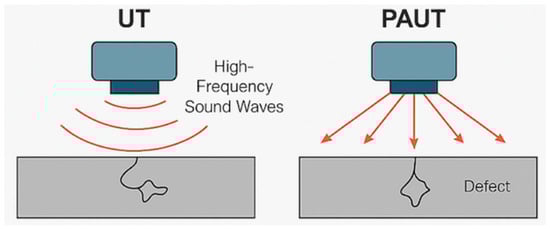
Figure 1.
Schematic of UT and PAUT operating principles.
2.2. Electromagnetic-Based Testing Methods
Electromagnetic-based NDT techniques are highly effective for inspecting conductive composite materials, especially CFRP. These methods operate by inducing and analyzing eddy currents within a material, allowing for the detection of surface and near-surface defects. The most commonly used technique is the conventional ECT, which provides a rapid and sensitive inspection without requiring surface contact. Recent advancements have led to the development of pulse eddy current testing (PECT), which is a time–domain method that enables deeper penetration and improved signal interpretation. The following subsections describe these two methods in detail.
2.2.1. Eddy Current Testing (ECT)
ECT is a versatile and highly sensitive NDE technique that relies on electromagnetic induction principles to detect and characterize defects or material properties in conductive materials [60]. By introducing an alternating current into the probe coil, ECT generates a magnetic field that induces eddy currents within the conductive material being inspected. These eddy currents, in turn, create a magnetic field that can be measured and analyzed to reveal information about the properties of the material and the presence of defects or anomalies.
ECT is widely used in various industries, including aerospace, automotive, and infrastructure, owing to its ability to quickly and accurately inspect components and ensure their structural integrity [61]. This technique is particularly useful for detecting surface and near-surface defects, such as cracks and changes in the material composition. Additionally, ECT can be used to measure material properties, such as conductivity and permeability, making it a valuable tool for material characterization and quality control [60].
One of the key advantages of ECT is its high sensitivity to small defects and variations in the material properties [62]. This sensitivity allows for the early detection of potential issues, enabling timely repair or replacement, and ultimately preventing catastrophic failures. Moreover, ECT can be performed without direct contact with the inspected material, making it suitable for use in situations where access is limited or surface conditions are challenging.
Several types of ECT probes have been designed for specific applications, offering unique benefits. For example, absolute probes are used to measure the total response of a material, whereas differential probes are used to measure the difference in the response between two coils. Encircling probes are used to inspect tubular components, whereas array probes consist of multiple coils that can be used to scan large areas. The choice of probe depends on the specific inspection requirements and nature of the material being tested [63,64,65].
Eddy currents are induced in the conductive regions of the composite, and the interaction of these currents with material properties can provide information regarding their condition. The electrical conductivity of CFRP materials depends on the volume fraction, structure, and orientation of the fibers, which can vary between the longitudinal and transverse directions. The conductivity of the fibers in the longitudinal direction is much higher (5000–50,000 S/m) than that in the transverse direction (10–100 S/m) [66].
Yi et al. [67] used eddy current pulse-compression thermography (ECPuCT) to characterize delamination in carbon CFRP materials. Compared with traditional single-pulse eddy current thermography, ECPuCT combines the Barker code-modulated eddy current excitation and pulse-compression techniques to improve the signal-to-noise ratio. The results show that the proposed ECPuCT approach can detect delamination depths ranging from 0.46 mm to 2.30 mm, and both the crossing point and skewness features have a monotonic relationship with delamination depth.
Pelkner et al. [68] conducted ECT on composite pressure vessels and found that it can detect leakage from both inside and outside on the CFRP vessel with a metallic liner. Moreover, ECT demonstrated considerable advantages in the detection of CFRP ropes. ECT offers a high inspection speed and the unique benefit of being a non-contact inspection method. It displays strong capability for detecting near-surface defects in CFRP ropes, making it a valuable technique for specific applications [56].
2.2.2. Pulse Eddy Current Testing (PECT)
PECT is a time–domain electromagnetic NDT method developed to overcome the limitations of conventional sinusoidal ECT, particularly in the inspection of multilayer, coated, or corrosion-prone conductive materials. Unlike traditional ECT, which uses a continuous wave with a fixed frequency, PECT employs short broadband current pulses to generate transient eddy currents. These eddy currents diffuse over time, allowing the detection of both surface and subsurface flaws by analyzing the time-dependent response signal [69].
The operating principle of PECT is based on electromagnetic induction. The transmitter coil generates a pulsed magnetic field, inducing transient eddy currents in the conductive test object. These eddy currents diffuse and decay according to local conductivity, permeability, and the presence of discontinuities. A receiver coil captures the time-varying response, which is then analyzed to extract features such as the peak amplitude, rise time, decay rate, and zero-crossing time, which are indicative of the defect type, depth, and severity [69].
PECT offers several advantages over conventional ECT, notably, its enhanced penetration depth, reduced sensitivity to lift-off variations, and capability to operate through coatings or insulation. These features make it particularly valuable for corrosion under insulation (CUI) detection, aircraft fuselage inspections, and structural health monitoring (SHM) in offshore, aerospace, and automotive applications. For example, Zhang et al. [70] demonstrated a rectangular PECT probe for imaging and quantifying surface and subsurface metal losses in lightweight automotive alloy components. Their system utilized the peak amplitude and time–domain fitting of A-scan signals to accurately estimate the defect depth, which was further visualized using C-scan pseudo-3D imaging.
Sensor design is another area in which PECT has advanced significantly. Tytko et al. [71] proposed an innovative I-core sensor for the internal inspection of conductive tubes, addressing the limitations posed by external access, wall curvature, and lift-off variability. Their comparative analysis between air-core and I-core configurations showed that the latter achieved significantly higher sensitivity and impedance responses for both magnetic and non-magnetic materials, particularly when detecting inner-wall thinning and artificial defects.
Further enhancements in system accuracy and signal interpretation have been achieved using resonant eddy current sensors and digital signal acquisition methods. Ma et al. [72] introduced an LC resonator-based PECT system for inspecting CFRP materials. Their approach utilized inductance-to-digital converters (LDCs) to detect shifts in the resonant frequency, which correlate with changes in conductivity caused by defects. Their study confirmed an improved sensitivity and signal-to-noise ratio, even under variable lift-off and surface conditions.
PECT has also shown promise in the agricultural and environmental engineering contexts. Zhu et al. [73] analyzed the feasibility of using pulsed eddy current detection to assess soil salinization via conductivity changes. Their findings demonstrated that the depth of signal penetration and decay characteristics could be effectively correlated with soil conductivity, offering the potential for rapid and non-contact field assessment tools.
Hybrid systems have emerged in aerospace and marine applications, where defect access may be limited and coatings are prevalent. Zheng et al. [69] proposed a dual-mode composite probe that integrates PECT with electromagnetic ultrasonic testing (EMUT). Their experiments showed that although PECT is effective for surface and near-surface corrosion or thinning, EMUT complements it by detecting deeper flaws. This hybrid configuration improved the detection range and reliability of ship hulls, offshore platforms, and pipelines.
Despite these advancements, PECT is not without limitations. The skin effect and signal diffusion can limit the detectability of deep defects. The interpretation of time–domain signals, particularly under multilayered or anisotropic conditions, remains complex. Furthermore, sensor alignment, probe geometry, and environmental noise can introduce variability in the signal acquisition. To address this, researchers such as Zhang et al. explored digital filtering, linear fitting, and feature extraction techniques to improve the defect classification and localization [70].
Table 2 presents a comparative overview of electromagnetic-based NDT methods, specifically ECT and PECT. Although both techniques are grounded in the principle of electromagnetic induction, they differ in the signal excitation, detection mechanisms, and application scope. The table summarizes their key characteristics, including the operational principles, advantages, limitations, and typical industrial use cases, particularly for metallic and composite structures, such as CFRP. This structured comparison highlights the advancements offered by PECT over conventional ECT in terms of depth profiling and liftoff tolerance.
Table 2.
Electromagnetic-based testing methods: description, advantages, limitations, and applications.
Figure 2 provides a schematic representation of the operating principles of ECT and PECT. The ECT uses a sinusoidal alternating current to generate stable eddy currents near the surface, making it ideal for detecting surface-breaking flaws. In contrast, PECT employs pulsed excitation to induce transient diffusive eddy currents that penetrate deeper into a material. These differences are illustrated in the figure, emphasizing that PECT has enhanced capability for subsurface defect detection and inspection through coatings or insulation.

Figure 2.
Schematic ECT and PECT operating principles.
2.3. Acoustic Emission (AET)
AET is an NDT technique that involves the detection and analysis of elastic waves generated within a material owing to the release of energy from localized sources of damage or structural changes [74,75,76]. The detectable frequencies were in the range of 100 kHz to 1 MHz, far beyond the audible human range [77]. Within this frequency range, acoustic emission signals can be quantitatively analyzed using parameters such as the event count, event rate, signal energy, amplitude, and rise time [78,79,80]. The b-value analysis, which examines the statistical distribution of signal amplitudes, is particularly effective for identifying early stage damage accumulation and predicting imminent structural ruptures [81,82].
In the context of composite materials, AET can be used to identify and monitor various damage mechanisms, such as fiber breakage, matrix cracking, delamination, and debonding, which occur during the loading or service life of composite structures [83,84].
The AET has emerged as a valuable SHM technique for FRP composites. Guo et al. [85] demonstrated the effectiveness of the InceptionTime deep-learning approach for classifying different damage modes in composite materials using AET data. Acoustic events increase with increasing stress in composite materials and begin to accumulate as early as 10% of the ultimate failure stress [86].
Piezoelectric sensors including piezoelectric ceramics (PZT) and piezoelectric polymers (PVDF) are commonly used to detect AET signals in FRP composites. These sensors can be embedded within a laminated composite structure, creating a “smart material” that can continuously monitor the structural conditions [87]. Embedding the sensors directly within the composite offers advantages over the traditional NDT methods that require external inspection.
However, the incorporation of piezoelectric AET sensors into FRP composites presents several challenges. Factors such as the sensor size, placement, and coupling with the composite can influence the reliability and accuracy of AET measurements [88]. Researchers have also investigated methods to artificially induce AET events, such as the use of pencil lead breaks, to correlate AET signals with specific damage mechanisms in composites [89]. Table 3 lists the advantages and limitations of AET for composite materials.
Table 3.
Advantages and limitations of AET for composite materials.
Figure 3 illustrates the key signal parameters commonly used in AET for damage characterization. These include the rise time, amplitude, event count, duration, and energy, which are extracted from transient waveform signals generated during material deformation or cracking. Such parameters are critical for identifying damage mechanisms and predicting failure progression, particularly when used in combination with a b-value analysis.
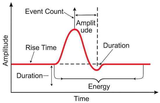
Figure 3.
Signal parameters in acoustic emission testing.
2.4. Thermography (TR) and Infrared Thermography (IRT)
In the field of NDT, TR has emerged as a promising method for detecting and evaluating damage in composite materials. TR can be categorized into four main types: active thermography, passive thermography, transient thermography, and IRT. Table 4 lists the advantages, limitations, and real-world applications of the TR techniques.
Table 4.
Advantages, limitations, and real-world applications of thermography techniques.
IRT is a widely used TR technique that involves the use of an infrared camera to record the thermal radiation emitted by the specimen surface [90]. IRT does not require direct contact with a surface and can be applied to parts with complex geometries [91].
Zhang et al. [92] used IRT in combination with pulsed thermography (PRT) and vibrothermography (VRT) for defect detection in CFRP and glass-fiber reinforced polymer (GFRP) specimens. The effectiveness of these techniques was subsequently validated using PAUT. However, this type of inspection requires the use of sensitive and expensive instrumentation and highly skilled inspectors to operate the instruments. In addition, the clarity of the defects may be limited if they are located too deep within the part. Fang and Maldague [93] presented a method for estimating the depth of simulated defects in composite materials using IRT, demonstrating the potential of this technique for NDE.
The repeatability and reliability of IRT inspections are crucial for their widespread adoption in industry. Švantner et al. [94] presented a study on the repeatability of the flash-pulse thermographic inspection of CFRP samples, providing valuable insights into the consistency and reproducibility of this technique.
An experimental comparison of IRT, PAUT, and ECT in the detection of CFRP ropes yielded important insights. In the case of bare CFRP ropes, IRT proved to be effective in detecting damage and delamination. However, when the ropes were coated with a protective polymer, the IRT was limited because infrared radiation was blocked by the coating [56].
Chang et al. [95] explored the use of infrared imaging techniques to detect defects in composite materials, particularly those made of FRP. The authors discussed how IR technology can be leveraged to identify internal flaws, delamination, and other structural issues in composite components without causing damage [96].
Similarly, Li et al. [97] described a simulation approach for modeling the physical characteristics of IR imaging systems. This has enabled researchers to better understand the capabilities and limitations of IR-based NDT methods when they are applied to composite materials. Swiderski [98] focused specifically on the application of IRT for NDT of CFRP composites and demonstrated how this imaging technique can be used to detect various types of defects, including impact damage, delamination, and manufacturing flaws, within CFRP structures.
Active thermography is a technique that involves applying a periodic thermal stimulus to a material and analyzing the resulting thermal response. The active TR approach involves using an external heat source, such as halogen lamps, to thermally excite the component, causing it to emit infrared radiation that can be captured by an infrared camera [99].
Lock-in thermography is a type of active thermography that effectively provides information regarding the properties of a material and the presence of defects [100,101]. Similarly, Boccardi et al. [102] investigated the use of lock-in thermography and UT for the inspection of impact-damaged composite materials. This study highlighted the complementary nature of these two NDT techniques for evaluating the integrity of composite structures.
Peeters et al. [103] presented an optimized dynamic line-scan thermographic detection method for inspecting CFRP inserts. Researchers have used finite element (FE) modeling and probability of detection (POD) analysis to improve the performance of IRT techniques. Recent studies have focused on applying POD analysis to active thermography techniques, including pulsed thermography [104]. In one such study, a set of thirty-five CFRP composite panels with impact damage was inspected using both pulsed thermography and a UT C-scan. The comparative experimental results and POD analysis showed that pulsed thermography testing had a smaller defect size at 90% POD with a 95% confidence level (a90/95) than UT for the specific parameters and setup used in the inspections.
The development of robust and reliable NDT approaches is essential to ensure the structural integrity of composite structures in various industries, particularly in critical applications such as aerospace [105]. Laureti et al. [106] explored the application of pulse-compression thermography and air-coupled UT for the detection of delamination in polymeric ablative materials, which are commonly used in aerospace applications.
Passive thermography relies on the natural thermal response of the material. Summa and Herrmann [107] discussed the use of quantitative passive thermography to study the behavior of polymers. This technique can be particularly useful for monitoring the fatigue and degradation of composite structures over time.
Jiang et al. [108] explored the integration of simulations and IRT for the study of heritage materials, which can also be applicable to the investigation of composite structures. By combining experimental data with numerical simulations, researchers can gain a deeper understanding of the thermal behavior of composite materials and improve the reliability of damage detection.
Transient thermography involves the use of an external heat source to thermally excite a component, causing it to emit infrared radiation that can be captured by an infrared camera. Kim et al. [109] focused on the use of thermal science and engineering principles to develop numerical models and simulations for the detection of defects in composite materials. Such computational approaches can complement experimental techniques and help optimize the inspection and monitoring of composite structures. Wei et al. [110] presented a deep learning-based approach for the segmentation of impact damage in curved CFRP laminates using IRT. This study demonstrates the potential of combining artificial intelligence with TR techniques for the automated detection and characterization of defects in complex composite structures.
Liu et al. [111] investigated the use of pulsed thermography and lock-in thermography to enhance the detection of defects in these materials. In addition to defect detection, the evaluation of the mechanical behavior of composite materials under various loading conditions is an important area of research. Pirinu et al. [112] utilized IRT to study the response of composite materials to low-velocity impact events, which can lead to complex damage patterns that are challenging to characterize using traditional methods.
Another aspect of research on IRT and composites is the evaluation of the fracture behavior of these materials, particularly in terms of delamination [113]. Pitarresi et al. [114] employed IRT in combination with techniques such as thermoelastic stress analysis to investigate the static and fatigue-induced delamination behavior of FRP composites under mode II loading conditions. This is crucial for quality control and safety assessments in industries such as aerospace and automotive, where composite materials are increasingly used [115].
In addition to composites, IRT has also been explored for the detection and characterization of defects in other materials, such as titanium–graphite fiber metal laminates [116].
Figure 4 illustrates the working principles of the two thermographic-based NDT techniques, TR and IRT. Both methods rely on the thermal contrast generated by defects within materials; however, they differ in their mechanisms of heat delivery, detection approach, and analysis. In TR, an external heat source (such as a flash lamp or hot air) is applied to the specimen surface [117,118,119,120]. As heat propagates through the material, internal flaws such as delamination, voids, or cracks disrupt the uniform heat flow, which is then observed as thermal anomalies using infrared sensors [115,121,122,123,124,125]. In contrast, IRT emphasizes real-time infrared radiation detection using a thermal camera without requiring external heating, which makes IRT suitable for both passive (natural thermal gradients) and active (stimulated) inspection modes [92,126,127,128,129]. The infrared image generated reveals differences in the surface temperature distribution, which can be correlated to underlying material inconsistencies [130,131,132,133,134]. This figure highlights how each method visualizes internal flaws and demonstrates the growing applicability of IRT for evaluating composite structures with minimal surface preparation.
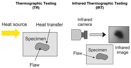
Figure 4.
Schematic illustration comparing TR and IRT.
2.5. Microwave (MW)
MW technology, a type of electromagnetic radiation with wavelengths ranging from approximately one meter to one millimeter and frequencies between 300 MHz and 300 GHz [135], has been widely used in various applications, including communication, radar, and the NDT of materials. In recent years, MW has emerged as a promising approach for evaluating composite materials [136].
Researchers have investigated the use of free-space MW techniques to simulate and detect damages in CFRP composites [137]. The simulation results demonstrated the feasibility of the MW method for identifying damage in CFRP composites, thereby setting the stage for further experimental validation. Building on this foundation, researchers have examined the principles and applications of MW testing for both woven and nonwoven CFRP composites [138]. Their work provided a comprehensive overview of the successful application of MW to a range of CFRP composite materials, highlighting the versatility of this approach.
The potential of MW techniques has also been explored beyond that of carbon fiber composites. For instance, researchers have investigated the use of MW reflectometry for NDT of nonmetallic pipelines [139]. This exploration suggests the potential of MW techniques to be expanded to different composite-based infrastructure systems. Furthermore, the research community has studied the use of MW in FRP composites, indicating the broader applicability of MW methods across various composite-material systems.
Rahman et al. [2] employed MW on glass-fiber reinforced epoxy (GRE) and high-density polyethylene (HDPE) specimens containing holes and notches. They used one K-band circular waveguide probe and two (K- and K-band) rectangular waveguide probes and found that the circular waveguide probe showed better detection based on the GRE sample.
To improve the data analysis and interpretation capabilities of the MW techniques, researchers have developed sophisticated analytical approaches. One such effort involves the use of a k-means clustering algorithm to enhance the accuracy and reliability of MW for identifying defects in composite materials [140,141,142,143]. Table 5 lists the advantages and limitations of the MW for composite materials.
Table 5.
Microwave testing for composite materials: description, advantages, limitations, and applications.
Figure 5 illustrates the two typical MW configurations used for composite and polymeric materials. In a free-space MW, an antenna directs microwave radiation toward the specimen, with reflected signals captured and analyzed for defect detection. In guided-wave setups, open-ended rectangular waveguides are used to improve the coupling efficiency and spatial resolution for localized flaw identification. Both configurations support various frequencies and probe geometries, such as K-band circular and rectangular waveguides, making them suitable for inspecting CFRP, GRE, and HDPE components.
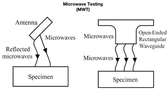
Figure 5.
Schematic of microwave testing using an antenna and using an open-ended rectangular waveguide.
2.6. Radiographic-Based Testing Methods
Radiographic-based NDT methods utilize ionizing radiation or X-rays to visualize internal structures and defects within composite materials. These techniques are particularly valuable for detecting voids, delamination, inclusions, and fiber misalignments, which may not be accessible to surface-based methods. Traditional RT relies on films or detectors to capture radiation-differential images, whereas modern DRT and XCT provide enhanced sensitivity, image processing capabilities, and 3D visualization. The following subsections describe these radiographic techniques in detail and highlight their respective capabilities and limitations.
2.6.1. Radiography Testing (RT)
The RT is a widely used NDE technique that employs ionizing radiation to inspect and evaluate the internal structure and integrity of materials, components, and structures. The fundamental principle of RT is the differential attenuation of radiation as it passes through an inspected object, which is affected by the density and thickness of the material [144].
X-rays and gamma rays are the two primary forms of ionizing radiation used in RT applications [145]. Although both types of radiation can penetrate materials, there are key differences between them, as listed in Table 6.
Table 6.
The different between X-ray and Gamma-ray.
The basic concept of RT applications involves placing the inspected object between the radiation source and detector, such as film or digital imaging sensors [146]. As radiation passes through an object, the varying densities and thicknesses of the material attenuate the radiation differently, creating a radiographic image that reveals the internal structure and any potential defects or anomalies [147].
RT is widely used in various industries, including aerospace, manufacturing, oil and gas, and infrastructure, to assess the integrity of materials, detect flaws, and ensure the safety and performance of critical components [148]. However, it is important to note that the use of ionizing radiation in RT applications carries potential health risks and must be carefully managed [149]. Exposure to high levels of radiation can have harmful effects on the human body, such as increased risk of cancer and radiation sickness. Strict safety protocols, including the use of shielding, remote handling, and personal protective equipment, are essential to minimize radiation exposure and ensure the safety of workers and the general public.
The unique properties and complex structures of composite materials present challenges and opportunities for RT applications. Composite materials composed of two or more distinct materials often exhibit significant variations in density and composition within a single component [5]. This heterogeneity can pose difficulties for traditional radiographic techniques, because the differential attenuation of radiation may not always provide clear and interpretable images.
Anoshkin et al. [150] conducted experimental studies to investigate the radiographic signs of major types of defects commonly found in polymeric composite materials (PCMs), such as interlayer delamination, pores, and wrinkles. A blade straightener was used as an example to evaluate the effectiveness of the microfocus X-ray method in detecting and characterizing these defects. The results of this study demonstrated that the microfocus X-ray method can detect defects as small as 0.5 mm in size. This high sensitivity to small defects makes the microfocus X-ray method a valuable tool for the NDE of PCM components, enabling the early detection of defects that could compromise the structural integrity of the material. The findings of this study highlight the potential of the microfocus X-ray method for ensuring the quality and reliability of PCM components in various industries.
Sahoo et al. [151] conducted a study on the quantitative assessment of thermal liner delamination in large-size composite rocket boosters using X-rays. This study aimed to address the limitations of UT in quantitatively assessing large delaminations and the lack of detailed information provided by tap testing. Although tap testing can reveal the presence of humps or defects, it does not provide comprehensive information regarding delamination size and extent. The results of this study demonstrated that RT could reveal additional delamination areas beyond those detected by tap testing, highlighting the effectiveness of RT in providing detailed and accurate information regarding the size and location of delaminations in large composite structures. The use of RT in this context shows its potential as a valuable tool for the NDE of composite materials in the aerospace industry.
Endrizzi et al. [152] characterized the drop-weight impact damage in composite structures by combining X-ray and UT C-scans, particularly those caused by low-velocity impacts. Low-velocity impact damage can lead to barely visible damage modes, such as matrix cracking, delamination, and fiber breakage. The UT C-scan showed large delamination and additional damage along the fiber directions. X-ray imaging was able to detect damage along the fiber directions, as well as other small-scale defects. X-ray imaging provides three sample representations: absorption, differential phase, and dark-field. Dark-field imaging is particularly useful for detecting cracks and voids smaller than the spatial resolution. However, the delamination orientation must not be parallel to the radiation beam [153].
2.6.2. Digital Radiography Testing (DRT)
DRT is an RT technique that utilizes digital detectors instead of traditional film to capture radiographic images. The detector is connected to a computer that processes and displays the images on a monitor. DRT is widely used in various industries, including aerospace, automotive, manufacturing, and healthcare, to inspect and evaluate the internal structure and integrity of materials, components, and structures.
DRT offers several advantages over traditional film-based radiography, particularly in the inspection of composite materials. The high sensitivity and resolution of digital detectors enable the detection of small defects, such as delamination, cracks, and voids, which may not be visible using traditional methods. Furthermore, digital image processing techniques such as contrast enhancement and edge detection can improve the visibility of defects and facilitate image interpretation.
The use of DRT is particularly beneficial for inspecting complex geometries and thick composite materials, which can be challenging when using traditional RT techniques. The ability to acquire images quickly and process them in real time can also improve the inspection efficiency and reduce the overall cost of NDE. For instance, Li et al. [154] conducted case studies and field applications using DRT to inspect insulated pipelines, demonstrating its effectiveness in detecting defects without the need to remove insulation layers.
However, some challenges are associated with the use of DRT. Kusk et al. [155] investigated the impact of the anode heel effect on image quality in DRT. The anode heel effect refers to the non-uniform intensity distribution of the X-ray beam due to the angled orientation of the X-ray anode. This effect can lead to image artifacts and reduced image quality.
Kraai [156] discussed the advantages of digital detector array (DDA) technology over conventional film-based radiography, such as improved POD and faster throughput. However, DDA systems are more expensive than traditional film-based equipment, which presents an investment challenge for some industrial facilities. In addition, specialized training may be required to transition radiographic technicians from film-based techniques to digital techniques.
Figure 6 presents a comparative schematic of RT and DRT, both of which rely on the attenuation of X-rays or gamma-rays as they pass through the specimen. In conventional film-based RT, a radiographic film placed behind an object captures the transmitted radiation, producing a static image that requires chemical development. In contrast, DRT replaces the film with a digital detector, such as a flat panel or imaging plate, allowing real-time acquisition, digital enhancement, and efficient data storage. This figure highlights the shared principles and distinct advantages of DRT in terms of speed, safety, and image-processing capabilities.
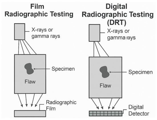
Figure 6.
Schematic of radiographic testing using film and using digital detector.
2.6.3. X-Ray Tomography (XCT)
XCT has revolutionized the field of composite material research as a powerful non-destructive 3D imaging technique. By capturing a series of X-ray projection images at various angles and computationally reconstructing them into a 3D digital representation, XCT provides unparalleled insights into the internal features of complex materials. This information is vital to understand the relationship between the microstructure of a composite and its macroscopic, mechanical, thermal, and other functional properties.
Over the past decade, advancements in XCT technology have significantly expanded its applications in composite materials research. Improvements in spatial resolution, reduced acquisition times, and increased accessibility of laboratory XCT systems have enabled researchers to explore new frontiers in composite-material analysis.
A key application of XCT in composite material research is the investigation of holes drilled into CFRP composites [157]. By analyzing the quality and characteristics of these holes, researchers can optimize the assembly and joining processes for composite structures. XCT has also been instrumental in examining the internal damage and defects within sandwich composite structures subjected to low-velocity impact [158]. The insights gained from these studies provide valuable insights into the failure mechanisms of composite materials.
Moreover, XCT data have been used to develop predictive models for the mechanical properties of composite materials [159]. These models aid in the design and optimization of composite components, reducing the need for time-consuming and costly experimental trials. Additionally, synthetic datasets generated from XCT data have been employed to create automated segmentation algorithms and streamline the analysis of composite materials [160].
XCT has also provided an in-depth overview of the technical aspects and applications of polymer composites [161]. Researchers have used XCT to study the manufacturing processes, tensile and compression loading, fatigue, and impact damage to composite materials. Furthermore, methodical parametric studies have been conducted using XCT to determine the optimal image segmentation thresholds for accurately quantifying important microstructural features in composites, such as the fiber orientation and porosity [162].
The non-destructive nature of XCT allows for the evaluation of internal structures and damage states in “active twist” composite structures, which are designed to undergo controlled deformation for applications such as morphing aircraft wings [163]. In addition, XCT was compared with traditional destructive cross-sectioning and optical microscopy techniques, demonstrating that XCT can provide similar or superior information without sample preparation.
Multiscale XCT has been employed to assess the internal structure and impact behavior of ballistic-resistant composite panels made from thermoplastic polymer matrices reinforced with aramid fabrics [164]. XCT has also been used to investigate the damage initiation and progression in composite materials under loading [165]. To further enhance the capabilities of XCT, researchers have studied the effects of this technique on the properties and performance of composite materials [166].
Advanced image analysis techniques have been developed for the high-precision segmentation of challenging XCT data of composite samples, enabling accurate quantitative analysis [167]. Moreover, XCT has been combined with other NDT methods such as UT to provide a more comprehensive understanding of impact damage in composite structures [168]. High-resolution synchrotron radiation XCT (SR-XCT) has been utilized to investigate the microstructural evolution of composite materials during dynamic processes, such as oxidation at high temperatures [169].
Figure 7 illustrates the operating principle of XCT, which is a powerful NDT method that reconstructs 3D images of a specimen’s internal structure. In XCT, a specimen is placed between a rotating X-ray source and detector array. As the sample rotates, multiple two-dimensional (2D) radiographic projections are captured from different angles. These projections are then processed using tomographic reconstruction algorithms to generate a 3D volumetric image. This technique allows for the precise characterization of internal features, such as the porosity, delamination, fiber orientation, and embedded defects in composite and metallic materials.

Figure 7.
Schematic illustration of X-ray computed tomography (XCT).
Table 7 presents a comparative overview of radiographic-based NDT methods, including traditional RT, DRT, and XCT. Each method is described in terms of its working principles, advantages, limitations, and typical applications in composite-material inspection. This consolidated view highlights the evolution of conventional film-based techniques to advanced 3D imaging and digital diagnostics, providing insight into their suitability across different industrial contexts.
Table 7.
Radiographic-based NDT methods: description, advantages, limitations, and applications.
2.7. Comparative Classification of NDT Techniques
NDT techniques differ significantly in their physical principles, operating conditions, and defect-detection capabilities. This section provides a comparative classification of the previously described methods to facilitate a systematic understanding and address reviewer feedback. The key parameters considered include the operating frequency range of the technique, the nature of coupling or contact required, the types of defects that can be detected (e.g., cracks, delamination, voids), and the typical defect size resolution.
These factors are critical in selecting the appropriate NDT method for specific composite or metallic applications, particularly in the aerospace, automotive, and civil infrastructure sectors. For instance, while conventional UT offers deep penetration for internal defect detection, eddy-current-based methods such as ECT and PECT provide high sensitivity to surface and near-surface flaws. AET stands out for its capability for real-time damage monitoring, whereas radiographic and thermographic techniques can be used to visualize internal structures non-invasively.
Table 8 presents a unified comparison of all the electromagnetic, acoustic, thermal, and radiographic NDT techniques discussed in Section 2.1, Section 2.2, Section 2.3, Section 2.4, Section 2.5 and Section 2.6. This summary enables readers to quickly identify the most suitable method based on the inspection depth, defect size, and material condition.
Table 8.
Comparative classification of NDT techniques.
3. Literature Review Summary and Key Findings
This section presents the results of a systematic review of 120 articles published between 2015 and 2025, with the aim of identifying the most studied and applied NDT methods for composite materials. This review shows clear research priorities, emerging innovations, and persistent gaps in the current body of knowledge.
3.1. Dominance of Ultrasonic and Thermographic Methods
The analysis confirmed that UT remains the most extensively researched and applied NDT technique for composite materials, accounting for approximately 45% of reviewed articles. Its widespread use is attributed to its capability to detect subsurface defects, such as delamination, disbonding, and porosity with reasonable reliability [6,41,42,43,44]. Despite this, UT faces limitations owing to the anisotropic nature of composite materials, which affects wave propagation, signal attenuation, and defect resolution. Advanced techniques, such as PAUT have been introduced to overcome these challenges, providing improved sensitivity, imaging flexibility, and faster scanning capabilities [41,42,43,44]. PAUT was reported in 20% of the reviewed studies, emphasizing its emerging role as a superior alternative to conventional UT for complex composite structures.
IRT, both passive and active, has been highlighted in 25% of the reviewed literature as a preferred method for non-contact surface and near-surface inspection [92,93]. IRT’s advantages include its applicability to large areas and complex geometries without requiring surface contact or couplants. However, environmental factors, such as the ambient temperature and surface emissivity, can affect its reliability, particularly for detecting subsurface defects deeper within the material [94,95,96].
3.2. Emerging but Underutilized Methods
Although traditional techniques dominate, this review also identifies promising emerging methods that remain underutilized in industrial applications. Notably, despite its non-contact nature, deep penetration capability, and environmental safety, MW testing has only been reported in 5% of the reviewed articles. The complexity of probe design and signal interpretation has limited its widespread adoption, although studies have highlighted its potential for detecting hidden defects in FRP and carbon CFRP composites [136,137,138].
Similarly, DRT and XCT have demonstrated exceptional imaging capabilities for internal defect visualization, including porosity, fiber misalignment, and delamination [150,151,152]. Despite this, concerns over radiation exposure, equipment cost, and operational safety limit their frequent use in routine inspections, particularly outside specialized industries, such as aerospace.
AET, appearing in 10% of the reviewed literature, presents an attractive solution for real-time SHM by detecting damage mechanisms, such as fiber breakage and matrix cracking during operation [85,87]. However, its effectiveness is limited by noise sensitivity and difficulty localizing acoustic sources in large or complex structures [88,89].
To complement the tabulated findings, Figure 8 presents a visual summary of the reported frequencies of each NDT method identified in the reviewed literature. UT and IRT clearly dominate, with emerging methods, such as MW and XCT, showing lower but growing research attention. This distribution highlights the reliance on traditional methods, while pointing to opportunities for diversifying industrial practices through advanced techniques.
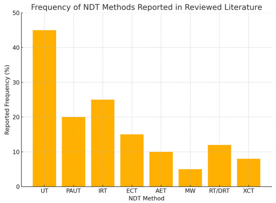
Figure 8.
Reported frequency of NDT methods applied to composite materials based on the review of 120 research articles [1,2,3,4,5,6,7,8,9,10,11,12,13,14,15,16,17,18,19,20,21,30,31,33,34,35,36,37,38,39,40,41,42,43,44,45,46,47,48,49,50,51,52,53,56,57,58,64,65,66,67,68,72,74,75,77,81,83,84,85,86,87,88,89,90,92,93,94,95,97,98,99,100,101,102,103,104,106,107,110,111,112,113,114,115,116,122,123,124,125,126,128,129,131,133,135,136,137,138,139,140,142,149,150,151,152,153,157,158,159,161,162,163,164,166,168,169,170,171,172].
3.3. Summary of Reported Frequency and Key Insights
Table 9 summarizes the frequency of NDT techniques reported in the reviewed literature and highlights their key findings. This comparative analysis not only reinforces the dominance of UT and IRT but also draws attention to underexplored yet promising methods such as MW and DRT.
Table 9.
Key findings and frequency of use of different NDT techniques.
This summary reinforces that while industry tends to favor UT and IRT for their reliability and cost-effectiveness, future research and application development should aim to expand the industrial readiness of advanced techniques, such as MW, DRT, and XCT, especially as manufacturing moves toward Industry 4.0 integration.
4. Perspective on Future Trends and Potential Applications
Based on the synthesis of 120 reviewed studies, it is evident that the NDT of composite materials has evolved significantly but still faces limitations that hinder its full industrial potential. As industries such as aerospace, renewable energy, oil and gas, and transportation increasingly rely on advanced composites, future research and industrial efforts must focus on overcoming these barriers by advancing the NDT capabilities in the following key areas.
To frame the direction of future research and industrial implementation, Figure 9 presents a technology roadmap highlighting four interconnected trends poised to shape the next generation of NDT for composite materials. These include AI for automated data interpretation, digital twin technologies for real-time structural simulation, IoT for sensor-driven remote monitoring, and multimodal NDT for holistic defect detection through combined methods. These trends are expected to converge, transforming the traditional NDT into an intelligent, predictive, and fully integrated quality assurance system.
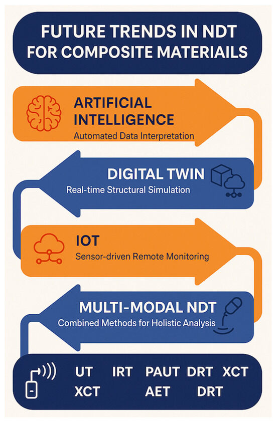
Figure 9.
Technology roadmap illustrating four major future trends.
4.1. Adoption of Multimodal and Hybrid NDT Systems
One of the most significant advancements anticipated in the field of NDT for composite materials is the transition from single-method inspection to multimodal and hybrid systems. While individual methods such as UT, PAUT, IRT, and MW testing have demonstrated distinct advantages, their standalone application often limits comprehensive defect characterization, particularly in thick, multilayered, or anisotropic composite structures [41,42,43,44].
Multimodal NDT systems aim to overcome these limitations by integrating multiple inspection techniques into a unified framework, allowing complementary methods to work in parallel or in sequence. Such systems enable cross-validation of defect indications, improved sensitivity across various defect types, and enhanced localization accuracy. For example, although UT and PAUT provide high-resolution subsurface defect detection, IRT offers rapid, non-contact surface scanning, and MW testing contributes to deep penetration capability without requiring coupling agents.
Figure 10 illustrates a conceptual schematic of a multimodal NDT system integrating the UT, PAUT, IRT, and MW methods. Each method is fed into a centralized data fusion module, where heterogeneous data are combined to create a more complete diagnostic profile [170,171,172,173,174]. These fused data are then processed through AI-based analysis, leveraging machine learning (ML) algorithms to automate defect classification and severity assessments [175,176]. The output is a detailed defect map that enables more accurate and reliable decision making for quality assurance and SHM [177].
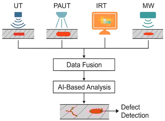
Figure 10.
Schematic of a multimodal NDT system integrating UT, PAUT, IRT, and MW methods.
4.2. Digital Twin and Industry 4.0 Integration
The next frontier in NDT is digitalization and real-time data integration. Digital twins, which are virtual models that replicate the physical behavior of composite structures, are gaining traction as predictive maintenance tools [178,179,180]. By integrating live data from NDT systems, such as AET and PAUT, these digital twins can simulate defect progression and estimate remaining useful life (RUL) [48,181,182]. Such predictive capabilities enable industries to transition from reactive to proactive maintenance strategies, reducing downtime, and extending asset life cycles [183,184,185,186].
4.3. Embedded and Wireless Structural Health Monitoring
Recent developments in embedded sensor technologies, such as PZT sensors, fiber-optic sensors, and wireless AET arrays, offer the potential for continuous in situ health monitoring without interrupting operations [187,188,189]. These embedded SHM systems allow for the real-time detection of damage mechanisms, such as delamination, fiber breakage, and matrix cracking [87,88,190,191]. The deployment of wireless and battery-free sensors further enhances the feasibility of integrating SHM into large-scale structures such as wind turbine blades, pipelines, and aerospace components [192,193,194,195,196].
4.4. Artificial Intelligence and Automated Defect Interpretation
As the volume of NDT data has increased with advanced sensing technologies, AI and ML offer powerful tools for automating data analysis. AI algorithms, including deep learning frameworks such as InceptionTime, have already shown promise for classifying damage types based on AET signals [85,197]. Future AI-driven systems will enhance defect characterization, reduce operator dependency, and enable faster decision making in manufacturing and maintenance workflows [198,199,200].
4.5. Environmentally Friendly and Operator-Safe Techniques
Although radiographic methods such as DRT and XCT provide high-resolution imaging, health and environmental safety concerns limit their routine use. Safer alternatives such as MW and ECT are gaining attention because of their non-ionizing nature, environmental safety, and effectiveness in detecting deep or hidden defects [97,98,99]. Promoting these safer NDT methods aligns with global occupational safety and sustainability goals.
To better illustrate the current technological landscape, Table 10 summarizes the key advantages and limitations of the major NDT techniques reviewed. This comparison not only highlights their strengths but also exposes critical gaps that justify the need for hybrid approaches, digital enhancements, and standardized implementation.
Table 10.
Advantages and limitations of NDT techniques based on composite materials.
4.6. Standardization and Industrial Certification
Despite the technological advancements in NDT, the lack of standardized calibration procedures, reference materials, and data interpretation guidelines remains a significant barrier to its widespread adoption. The development of internationally recognized standards and certification frameworks is crucial to ensure repeatable, reliable, and comparable results across industries and applications [150,151,152,153]. Collaborative efforts among research institutions, industry leaders, and standardization bodies are essential to close this gap.
5. Conclusions
This review comprehensively analyzes the state-of-the-art NDT techniques applied to composite materials, including UT, PAUT, AET, IRT, ECT, MW methods, RT, DRT, and XCT. A systematic review of 120 research articles revealed that UT and IRT remain the most widely applied methods primarily because of their accessibility, reliability, and established industrial practices.
However, emerging methods such as MW, DRT, AET, and XCT, are still underutilized in practice. These techniques offer enhanced defect characterization, safer operation, and integration potential with digital manufacturing environments, but face challenges related to cost, data interpretation complexity, and a lack of standardized procedures.
The key findings of this review are as follows:
- No single NDT method is universally sufficient for all composite material challenges.
- Multimodal and hybrid NDT approaches offer the most comprehensive defect-detection capability.
- The integration of NDT with Industry 4.0 technologies, such as digital twins and real-time SHM, represents the next frontier.
- AI and ML have shown significant potential for automating defect recognition and improving data analysis reliability.
- Environmentally friendly and operator-safe alternatives such as MW and ECT should be further explored and promoted.
- A major gap exists in the standardization and certification of advanced NDT methods, which require collaborative efforts among industry, academia, and regulatory bodies.
Future Outlook
To unlock the full potential of NDT in composite-material applications, future research and industrial efforts should focus on the following:
- Advancing hybrid inspection systems that combine the strengths of multiple methods.
- Developing AI-powered analytics for real-time defect interpretation.
- Promoting sustainable and safe inspection methods.
- Establishing internationally recognized standards and certification protocols to ensure consistency and industry-wide adoption.
In line with these directions, future research will explore the integration of sensor fusion and digital twin technology for real-time SHM. By combining advanced sensing hardware with virtual modeling environments, future NDT systems can move beyond passive defect detection to predictive diagnostics, enabling intelligent decision-making, risk-based maintenance, and extended asset lifecycles.
Addressing these future priorities will help elevate the NDT from a traditional quality control tool to a digitally enabled, intelligent infrastructure management platform tailored for next-generation composite structures.
Author Contributions
Conceptualization, J.L.T., M.T.H.S. and A.Ł.; methodology, J.L.T., F.S.S., J.J. and Z.O.; software, J.L.T.; validation, M.T.H.S., A.Ł., J.J., Z.O. and F.S.S.; formal analysis, J.L.T., M.T.H.S., J.J., Z.O. and A.Ł.; investigation, J.L.T. and F.S.S.; resources, J.L.T.; data curation, J.L.T.; writing—original draft preparation, J.L.T.; writing—review and editing, M.T.H.S., A.Ł., J.J., Z.O. and F.S.S.; visualization, J.L.T.; supervision, M.T.H.S., A.Ł., J.J., Z.O. and F.S.S.; project administration, F.S.S.; funding acquisition, M.T.H.S., J.J., A.Ł. and Z.O. All authors have read and agreed to the published version of the manuscript.
Funding
The authors are grateful for the financial support given by The Ministry of Higher Education Malaysia (MOHE) under the Higher Institution Centre of Excellence (HICOE2.0/5210004) at the Institute of Tropical Forestry and Forest Products. The paper is co-financed from the funds of the state budget under the program of the Minister of Science of Poland under the name Polish Metrology II Programme, project number No. PM-II/SP/0040/2024/02 entitled “Multisensor system for measuring thermo-mechanical interactions together with a comprehensive analysis of the state”, amount of funding 968 000,00 PLN, total project value 968 000,00 PLN, Poland. The paper is co-financed from the funds of the state budget under the program of the Minister of Science of Poland under the name Polish Metrology II Programme, project no. PM-II/SP/0093/2024/02 entitled “Building the algorithms of blind signal processing based on geometrical structure of information”. Founding amount: 966 800.00 PLN. Total value of the project: 966 800.00 PLN, Poland. This research was partially financed by the Ministry of Science and Higher Education of Poland with allocation to the Faculty of Mechanical Engineering, Bialystok University of Technology, for the WZ/WM-IIM/5/2023 and WZ/WM-IIB/4/2023 academic projects in the mechanical engineering and biomedical engineering disciplines.
Data Availability Statement
No new data were created in this study.
Acknowledgments
The authors would also like to express their gratitude to the Department of Aerospace Engineering, Faculty of Engineering, Universiti Putra Malaysia, and the Laboratory of Biocomposite Technology, Institute of Tropical Forestry and Forest Product (INTROP), Universiti Putra Malaysia (HICOE) for their close collaboration in this study.
Conflicts of Interest
The authors declare no conflicts of interest.
References
- Saghir, F.; Gohari, S.; Mozafari, F.; Moslemi, N.; Burvill, C.; Smith, A.; Lucas, S. Mechanical Characterization of Particulated FRP Composite Pipes: A Comprehensive Experimental Study. Polym. Test. 2021, 93, 107001. [Google Scholar] [CrossRef]
- Ur Rahman, M.S.; Haryono, A.; Abou-Khousa, M.A. Microwave Non-Destructive Evaluation of Glass Reinforced Epoxy and High Density Polyethylene Pipes. J. Nondestruct. Eval. 2020, 39, 26. [Google Scholar] [CrossRef]
- Towsyfyan, H.; BiguriI, A.; Boardman, R.; Blumensath, T. Successes and Challenges in Non-Destructive Testing of Aircraft Composite Structures. Chin. J. Aeronaut. 2020, 33, 771–791. [Google Scholar] [CrossRef]
- Gandhi, N.; Rose, R.; Croxford, A.J.; Ward, C. Understanding System Complexity in the Non-Destructive Testing of Advanced Composite Products. J. Manuf. Mater. Process. 2022, 6, 71. [Google Scholar] [CrossRef]
- Gholizadeh, S. A Review of Non-Destructive Testing Methods of Composite Materials. Procedia Struct. Integr. 2016, 1, 50–57. [Google Scholar] [CrossRef]
- Herrmann, H.; Schwarz, M.; Summa, J.; Grossmann, F. Non-Destructive Testing for Evaluation of Defects and Interfaces in Metal-Carbon Fiber Reinforced. Int. J. Mater. Metall. Eng. 2017, 11, 546–552. [Google Scholar]
- Sathawane, A.A.; Singh, D. Study on Non-Destructive Testing for Structural Analysis. Int. J. Technol. Res. Eng. 2021, 8, 6–11. [Google Scholar]
- Elkolali, M.; Nogueira, L.P.; Rønning, P.O.; Alcocer, A. Void Content Determination of Carbon Fiber Reinforced Polymers: A Comparison between Destructive and Non-Destructive Methods. Polymers 2022, 14, 1212. [Google Scholar] [CrossRef]
- Ferreira, C.G.; Lopes, R.T.; dos Santos, T.M.P.; Oliveira, D.F.; Martins, F.D.F.; Pereira, G.R. Non-Destructive Inspection of Laminated Pipe Joints in Polymeric Composite Material Reinforced by Fiberglass. Nucl. Instrum. Methods Phys. Res. Sect. A 2018, 954, 161154. [Google Scholar] [CrossRef]
- Chen, J.; Yu, Z.; Jin, H. Nondestructive Testing and Evaluation Techniques of Defects in Fiber-Reinforced Polymer Composites: A Review. Front. Mater. 2022, 9, 986645. [Google Scholar] [CrossRef]
- De Almeida, P.D.; Pereira, G.R. Phased Array Inspection of Glass Fiber Reinforced Polymers Pipeline Joints. J. Mater. Res. Technol. 2019, 8, 4736–4740. [Google Scholar] [CrossRef]
- Quinn, J.A.; Davidson, J.R.; Bajpai, A.; Ó Brádaigh, C.M.; McCarthy, E.D. Advanced Ultrasonic Inspection of Thick-Section Composite Structures for In-Field Asset Maintenance. Polymers 2023, 15, 3175. [Google Scholar] [CrossRef] [PubMed]
- Zhongbing, L.U.O.; Song, Z.; Hengkui, Q.; Huanqing, C.A.O.; Huimin, S.U.; Li, L.I.N. Modelling and Wave Propagation Behavior of Phased Array Ultrasonic Testing on Carbon Fiber. Acta Mater. Compos. Sin. 2020, 35, 2829–2838. [Google Scholar]
- Taheri, H.; Hassen, A.A. Nondestructive Ultrasonic Inspection of Composite Materials: A Comparative Advantage of Phased Array Ultrasonic. Appl. Sci. 2019, 9, 1628. [Google Scholar] [CrossRef]
- Chaki, S.; Krawczak, P. Non-Destructive Health Monitoring of Structural Polymer Composites: Trends and Perspectives in the Digital Era. Materials 2022, 15, 7838. [Google Scholar] [CrossRef]
- Torbali, M.E.; Zolotas, A.; Avdelidis, N.P. A State-of-the-Art Review of Non-Destructive Testing Image Fusion and Critical Insights on the Inspection of Aerospace Composites towards Sustainable Maintenance Repair Operations. Appl. Sci. 2023, 13, 2732. [Google Scholar] [CrossRef]
- Li, Z.; Meng, Z. A Review of the Radio Frequency Non-Destructive Testing for Carbon-Fibre Composites. Meas. Sci. Rev. 2016, 16, 68–76. [Google Scholar] [CrossRef]
- Suhasini, M.U.; Reddy, K.A. A Comprehensive Study on Defects Parameters of Ferrous and Composite Materials Using Non Destructive Testing Methods. Int. J. Res. Trends Innov. 2017, 2, 108–111. [Google Scholar]
- Zhang, X.; Cheng, L.; Liu, Y.; Tao, B.; Wang, J.; Liao, R. A Review of Non-Destructive Methods for the Detection Tiny Defects within Organic Insulating Materials. Front. Mater. 2022, 9, 995516. [Google Scholar] [CrossRef]
- Mohseni, E.; Javadi, Y.; Sweeney, N.E.; Lines, D.; MacLeod, C.N.; Vithanage, R.K.W.; Qiu, Z.; Vasilev, M.; Mineo, C.; Lukacs, P.; et al. Model-Assisted Ultrasonic Calibration Using Intentionally Embedded Defects for in-Process Weld Inspection. Mater. Des. 2021, 198, 109330. [Google Scholar] [CrossRef]
- Boukani, H.H. Evaluation of the Reliability of Nondestructive Ultrasonic Inspection Methods for the Detection and the Characterization of Defects in Hydroelectric Turbine Welded Joints. Ph.D. Thesis, Université du Québec, Quebec, QC, Canada, 2018. [Google Scholar]
- Tai, J.L.; Sultan, M.T.H.; Shahar, F.S. Experimental Study on the Efficacy of Ultrasound in In-Situ Detection of Corrosion in Palm Oil Refining Equipment. J. Teknol. 2024, 86, 151–159. [Google Scholar] [CrossRef]
- Jiao, J.; Fan, Z.; Zhong, F.; He, C.; Wu, B. Application of Ultrasonic Methods for Early Detection of Intergranular Corrosion in Austenitic Stainless Steel. Res. Nondestruct. Eval. 2016, 27, 193–203. [Google Scholar] [CrossRef]
- Jadav, C.; Patel, S. Ultrasonic Testing for Determination Internal Flaws and Discontinuities in Metal Casting: A Review. Nat. Volatiles Essent. Oils 2021, 8, 4899–4918. [Google Scholar]
- Tai, J.L.; Sultan, M.T.H.; Tarasiuk, W.; Napiórkowski, J.; Łukaszewicz, A.; Shahar, F.S. Ultrasonic Velocity and Attenuation of Low-Carbon Steel at High Temperatures. Materials 2023, 16, 5123. [Google Scholar] [CrossRef]
- Alobaidi, W.M.; Alkuam, E.A.; Al-Rizzo, H.M.; Sandgren, E. Applications of Ultrasonic Techniques in Oil and Gas Pipeline Industries: A Review. Am. J. Oper. Res. 2015, 05, 274–287. [Google Scholar] [CrossRef]
- Suchato, N.; Sharples, S.; Light, R.; Kalashnikov, A. Experimental Setup of Continuous Ultrasonic Monitoring for Corrosion Assessment. In Proceedings of the 2017 IEEE International Ultrasonics Symposium (IUS), Washington, DC, USA, 6–9 September 2017; pp. 2–5. [Google Scholar] [CrossRef]
- Carboni, M.; Cantini, S. Advanced Ultrasonic “Probability of Detection” Curves for Designing in-Service Inspection Intervals. Int. J. Fatigue 2016, 86, 77–87. [Google Scholar] [CrossRef]
- Markert, M.; Brodscholl, R.; Katzmann, J. Development of an Ultrasonic Testing Method for Continuous Measurements on Concrete with Different Moisture Levels Under Compressive Fatigue Loading. Otto-Graf-J. Vol. 2020, 19, 131–146. [Google Scholar]
- Luiz, T.; Oliveira, L.; Hadded, M.; Mimouni, S.; Schaan, R.B. The Role of Non-Destructive Testing of Composite Materials for Aerospace Applications. NDT 2025, 3, 3. [Google Scholar] [CrossRef]
- Zarei, A.; Pilla, S. Laser Ultrasonics for Nondestructive Testing of Composite Materials and Structures: A Review. Ultrasonics 2024, 136, 107163. [Google Scholar] [CrossRef]
- Tai, J.L.; Sultan, M.T.H.; Shahar, F.S. Comparative Analysis of Ultrasonic Inspection Techniques for Corrosion Monitoring in Petrochemical Plants Using Analytic Hierarchy Process (AHP). Pertanika J. Sci. Technol. 2025, 33, 1439–1457. [Google Scholar] [CrossRef]
- Wang, B.; Zhong, S.; Lee, T.L.; Fancey, K.S.; Mi, J. Non-Destructive Testing and Evaluation of Composite Materials/Structures: A State-of-the-Art Review. Adv. Mech. Eng. 2020, 12, 1–28. [Google Scholar] [CrossRef]
- Small, S.W.; Wilson, H.M. Ultrasonic Testing of Carbon Fiber Bicycles. In Proceedings of the International Ultrasonic Testing Online Conference (UT-Online 2021), Online, 1–30 November 2021. [Google Scholar]
- Hassen, A.A.; Vaidya, U.K.; Clarkson, G.E. Innovative Nondestructive Ultrasonic Testing and Analysis for FRP Piping. In Proceedings of the CAMX 2015—Composites and Advanced Materials Expo, Dallas, TX, USA, 26–29 October 2015; pp. 914–921. [Google Scholar]
- Matalgah, K.; Ravindranath, P.K.; Pulipati, D.; Fleck, T.J. Automated Quantification of Interlaminar Delaminations in Carbon-Fiber-Reinforced Polymers via High-Resolution Ultrasonic Testing. Polymers 2023, 15, 4691. [Google Scholar] [CrossRef] [PubMed]
- Ellison, A.; Kim, H. Shadowed Delamination Area Estimation in Ultrasonic C-Scans of Impacted Composites Validated by X-Ray CT. J. Compos. Mater. 2020, 54, 549–561. [Google Scholar] [CrossRef]
- Ma, M.; Cao, H.; Jiang, M.; Sun, L.; Zhang, L.; Zhang, F.; Sui, Q.; Tian, A.; Liang, J.; Jia, L. High Precision Detection Method for Delamination Defects in Carbon Fiber Composite Laminates Based on Ultrasonic Technique and Signal Correlation Algorithm. Materials 2020, 13, 3840. [Google Scholar] [CrossRef]
- Jasiūnienė, E.; Mažeika, L.; Samaitis, V.; Cicėnas, V.; Mattsson, D. Ultrasonic Non-Destructive Testing of Complex Titanium/Carbon Fibre Composite Joints. Ultrasonics 2019, 95, 13–21. [Google Scholar] [CrossRef]
- Ibrahim, M.E. Ultrasonic Inspection of Hybrid Polymer Matrix Composites. Compos. Sci. Technol. 2021, 208, 5–13. [Google Scholar] [CrossRef]
- Rizwan, M.K.; Laureti, S.; Mooshofer, H.; Goldammer, M.; Ricci, M. Ultrasonic Imaging of Thick Carbon Fiber Reinforced Polymers through Pulse-Compression-Based Phased Array. Appl. Sci. 2021, 11, 1508. [Google Scholar] [CrossRef]
- Kappatos, V.; Asfis, G.; Salonitis, K.; Tzitzilonis, V.; Avdelidis, N.P.; Cheilakou, E.; Theodorakeas, P. Theoretical Assessment of Different Ultrasonic Configurations for Delamination Defects Detection in Composite Components. Procedia CIRP 2017, 59, 29–34. [Google Scholar] [CrossRef]
- Seo, D.W.; Jung, K.S.; Kim, Y.S.; Kim, H.J.; Na, W.S. Development of a New Temporary Attachment Technique for Detecting Debonding of a Composite Structure Using Impedance Based Non-Destructive Testing Method. Appl. Sci. 2021, 11, 10763. [Google Scholar] [CrossRef]
- Teng, L.; Zhou, Z. A Novel Non-Destructive Testing Method for Turbine Disks Using Dual Array Ultrasonic Transducer. Sci. Rep. 2022, 12, 9427. [Google Scholar] [CrossRef]
- Evans, E.E.; Brooks, R.A.; Liu, J.; Hall, Z.E.C.; Liu, H.; Lowe, T.J.E.; Withers, P.J.; Kinloch, A.J.; Dear, J.P. Comparison of X-Ray Computed Tomography and Ultrasonic C-Scan Techniques and Numerical Modelling of Impact Damage in a CFRP Composite Laminate. Appl. Compos. Mater. 2024, 31, 249–264. [Google Scholar] [CrossRef]
- Amif, M.A.; Jack, D.A. High-Resolution Ultrasound to Quantify Sub-Surface Wrinkles in a Woven CFRP Laminate. Materials 2024, 17, 2002. [Google Scholar] [CrossRef] [PubMed]
- Santos, M.J.; Santos, J.B.; Reis, P.; Amaro, A. Ultrasonic C-Scan Techniques for Damage Evaluation of Carbon Fiber Reinforced Polymers Submitted to Low Energy Impacts. Proc. Meet. Acoust. 2019, 38, 030002. [Google Scholar] [CrossRef]
- Wang, B.; He, P.; Kang, Y.; Jia, J.; Liu, X.; Li, N. Ultrasonic Testing of Carbon Fiber-Reinforced Polymer Composites. J. Sens. 2022, 2022, 5462237. [Google Scholar] [CrossRef]
- Wronkowicz-Katunin, A.; Mihaylov, G.; Dragan, K.; Timofiejczuk, A. Uncertainty Estimation for Ultrasonic Inspection of Composite Aerial Structures. J. Nondestruct. Eval. 2019, 38, 82. [Google Scholar] [CrossRef]
- Lim, J.S.; Park, T.S.; Choi, Y.M.; Park, I.K. Improvement in Accuracy of a Multi-Joint Robotic Ultrasonic Inspection System for the Integrity of Composite Structures. Appl. Sci. 2020, 10, 6967. [Google Scholar] [CrossRef]
- Bardis, K.; Avdelidis, N.P.; Ibarra-Castanedo, C.; Maldague, X.P.V.; Fernandes, H. Advanced Diagnostics of Aircraft Structures Using Automated Non-Invasive Imaging Techniques: A Comprehensive Review. Appl. Sci. 2025, 15, 3584. [Google Scholar] [CrossRef]
- Lopez-Hawa, H.; Vanpelt, A.; Emmanuel, S.; Yihun, Y. Automated Scanning Techniques Using UR5. J. Robot. 2019, 2019, 5304267. [Google Scholar] [CrossRef]
- Tunukovic, V.; McKnight, S.; Hifi, A.; Mohseni, E.; Pierce, S.G.; Vithanage, R.K.W.; Dobie, G.; MacLeod, C.N.; Cochran, S.; O’Hare, T. Human-Machine Collaborative Automation Strategies for Ultrasonic Phased Array Data Analysis of Carbon Fibre Reinforced Plastics. NDT E Int. 2025, 154, 103392. [Google Scholar] [CrossRef]
- Tai, J.L.; Grzejda, R.; Sultan, M.T.H.; Łukaszewicz, A.; Shahar, F.S.; Tarasiuk, W.; Rychlik, A. Experimental Investigation on the Corrosion Detectability of A36 Low Carbon Steel by the Method of Phased Array Corrosion Mapping. Materials 2023, 16, 5297. [Google Scholar] [CrossRef]
- Tai, J.L.; Sultan, M.T.H.; Shahar, F.S. Processing Plants Damage Mechanisms and On-Stream Inspection Using Phased Array Corrosion Mapping—A Systematic Review. Pertanika J. Sci. Technol. 2024, 32, 1665–1685. [Google Scholar] [CrossRef]
- Antin, K.N.; Machado, M.A.; Santos, T.G.; Vilaça, P. Evaluation of Different Non-Destructive Testing Methods to Detect Imperfections in Unidirectional Carbon Fiber Composite Ropes. J. Nondestruct. Eval. 2019, 38, 23. [Google Scholar] [CrossRef]
- Camineroa, M.A.; García-Morenoa, I.; Rodrígueza, G.P.; Chacónb, J.M. Internal Damage Evaluation of Composite Structures Using Phased Array Ultrasonic Technique: Impact Damage Assessment in CFRP and 3D Printed Reinforced Composites. Compos. B Eng. 2018, 165, 131–142. [Google Scholar] [CrossRef]
- Mohd Tahir, M.F.; Echtermeyer, A.T. Phased Array Ultrasonic Testing on Thick Glass Fiber Reinforced Thermoplastic Composite Pipe Implementing the Classical Time-Corrected Gain Method. J. Nondestruct. Eval. 2024, 43, 74. [Google Scholar] [CrossRef]
- Tai, J.L.; Sultan, M.T.H.; Shahar, F.S.; Łukaszewicz, A.; Oksiuta, Z.; Grzejda, R. Ultrasound Corrosion Mapping on Hot Stainless Steel Surfaces. Metals 2024, 14, 1425. [Google Scholar] [CrossRef]
- Abdelli, D.E.; Nguyen, T.T.; Clenet, S.; Cheriet, A. Stochastic Metamodel for Probability of Detection Estimation of Eddy-Current Testing Problem in Random Geometric. IEEE Trans. Magn. 2019, 55, 6200604. [Google Scholar] [CrossRef]
- Apostol, E.S.; Nedelcu, A.; Daniel, D.V.; Chiriţǎ, I.; Tǎnase, N. Mathematical Modeling of Eddy Current Non-Destructive Testing. In Proceedings of the 2017 10th International Symposium on Advanced Topics in Electrical Engineering (ATEE), Bucharest, Romania, 23–25 March 2017; pp. 469–474. [Google Scholar] [CrossRef]
- Tai, J.L.; Sultan, M.T.H.; Łukaszewicz, A.; Shahar, F.S.; Oksiuta, Z.; Krishnamoorthy, R.R. Enhancing Turnaround Maintenance in Process Plants through On-Stream Phased Array Corrosion Mapping: A Review. Appl. Sci. 2024, 14, 6707. [Google Scholar] [CrossRef]
- Farag, H.E.; Toyserkani, E.; Khamesee, M.B. Non-Destructive Testing Using Eddy Current Sensors for Defect Detection in Additively Manufactured Titanium and Stainless-Steel Parts. Sensors 2022, 22, 5440. [Google Scholar] [CrossRef]
- Zhang, R.; Wang, J.; Liu, S.; Ma, M.; Fang, H.; Cheng, J.; Zhang, D. Non-Destructive Testing of Carbon Fibre Reinforced Plastics (CFRP) Using a Dual Transmitter-Receiver Differential Eddy Current Test Probe. Sensors 2022, 22, 6761. [Google Scholar] [CrossRef]
- Abdalla, A.N.; Ali, K.; Paw, J.K.S.; Rifai, D.; Faraj, M.A. A Novel Eddy Current Testing Error Compensation Technique Based on Mamdani-Type Fuzzy Coupled Differential and Absolute Probes. Sensors 2018, 18, 2108. [Google Scholar] [CrossRef]
- Hachi, D.; Benhadda, N.; Helifa, B.; Lefkaier, I.K.; Abdelhadi, B. Composite Material Characterization Using Eddy Current by 3D FEM Associated with Iterative Technique. Adv. Electromagn. 2019, 8, 8–15. [Google Scholar] [CrossRef]
- Yi, Q.; Tian, G.Y.; Malekmohammadi, H.; Zhu, J.; Laureti, S.; Ricci, M. New Features for Delamination Depth Evaluation in Carbon Fiber Reinforced Plastic Materials Using Eddy Current Pulse-Compression Thermography. NDT E Int. 2019, 102, 264–273. [Google Scholar] [CrossRef]
- Pelkner, M.; Casperson, R.; Pohl, R.; Munzke, D.; Becker, B. Eddy Current Testing of Composite Pressure Vessels. Int. J. Appl. Electromagn. Mech. 2019, 59, 1221–1226. [Google Scholar] [CrossRef]
- Zheng, X.; Huang, J.; Luo, N. Enhanced Nondestructive Testing Using Pulsed Eddy Current and Electromagnetic Ultrasonic Techniques. Appl. Sci. 2024, 14, 6488. [Google Scholar] [CrossRef]
- Zhang, K.; He, Y.; Dong, Z. Pulsed Eddy Current Nondestructive Testing for Defect Evaluation and Imaging of Automotive Lightweight Alloy Materials. J. Sens. 2018, 2018, 1639387. [Google Scholar] [CrossRef]
- Tytko, G.; Yin, W.; Luo, Y.; Adamczyk-Habrajska, M. Eddy Current Testing of Conductive Tubes With the Employment of the I-Core Sensor. IEEE Access 2024, 12, 25525–25535. [Google Scholar] [CrossRef]
- Ma, M.; Liu, S.; Zhang, R.; Zhang, Q.; Wu, Y.; Chen, B. Non-Destructive Testing of Carbon Fiber-Reinforced Plastics (CFRPs) Using a Resonant Eddy Current Sensor. Sensors 2024, 24, 3449. [Google Scholar] [CrossRef]
- Zhu, W.; Zhang, L.; Peng, Y.; Zhang, Q.; Gao, M.; Fu, Y. Principle Analysis of Soil Electrical Conductivity Test Based on Pulsed Eddy Current. IOP Conf. Ser. Earth Environ. Sci. 2019, 242, 042018. [Google Scholar] [CrossRef]
- Romhány, G.; Czigány, T.; Karger-Kocsis, J. Failure Assessment and Evaluation of Damage Development and Crack Growth in Polymer Composites Via Localization of Acoustic Emission Events: A Review. Polym. Rev. 2017, 57, 397–439. [Google Scholar] [CrossRef]
- Kourkoulis, S.K.; Loukidis, A.; Pasiou, E.D.; Stavrakas, I.; Triantis, D. Response of Fiber Reinforced Concrete While Entering into the Critical Stage: An Attempt to Detect Pre-Failure Indicators in Terms of Non-Extensive Statistical Mechanics. Theor. Appl. Fract. Mech. 2023, 123, 103690. [Google Scholar] [CrossRef]
- Tai, J.L.; Sultan, M.T.H.; Łukaszewicz, A.; Siemiątkowski, Z.; Skorulski, G.; Shahar, F.S. Preventing Catastrophic Failures: A Review of Applying Acoustic Emission Testing in Multi-Bolted Flanges. Metals 2025, 15, 438. [Google Scholar] [CrossRef]
- Samborski, S.; Korzec, I. Application of the Acoustic Emission Technique for Damage Identification in the Fiber Reinforced Polymer Composites. Adv. Sci. Technol. Res. J. 2023, 17, 210–221. [Google Scholar] [CrossRef]
- Joseph, R.; Giurgiutiu, V. Non-Crack-Growth Acoustic Emission Observed in Controlled-Stress-Intensity-Factor High-Cycle-Fatigue Tests. Actuators 2023, 12, 93. [Google Scholar] [CrossRef]
- Ding, L.; Zhao, Y.; Pan, Y.; Fan, Y. Investigation on Acoustic Emission Characteristics of Fault Stick-Slip under Different Lateral Pressures. Sci. Rep. 2024, 14, 6718. [Google Scholar] [CrossRef]
- Zhou, Q.; Wen, B. Fatigue Damage Assessment Using Adaptive Acoustic Emission Waveform Analysis. Results Eng. 2025, 27, 105713. [Google Scholar] [CrossRef]
- Jung, D.; Yu, W.R.; Ahn, H.; Na, W. New B-Value Parameter for Quantitatively Monitoring the Structural Health of Carbon Fiber-Reinforced Composites. Mech. Syst. Signal Process 2022, 165, 108328. [Google Scholar] [CrossRef]
- Triantis, D.; Pasiou, E.D.; Stavrakas, I.; Kourkoulis, S.K. Revealing the Proximity of Concrete Specimens to Their Critical Damage Level by Exploring the Cumulative Counts of the Acoustic Emissions in the Natural Time Domain. Materials 2024, 17, 1017. [Google Scholar] [CrossRef]
- Brunner, A.J. Identification of Damage Mechanisms in Fiber-Reinforced Polymer-Matrix Composites with Acoustic Emission and the Challenge of Assessing Structural Integrity and Service-Life. Constr. Build. Mater. 2018, 173, 629–637. [Google Scholar] [CrossRef]
- Šofer, M.; Cienciala, J.; Fusek, M.; Pavlicek, P.; Moravec, R. Damage Analysis of Composite CFRP Tubes Using Acoustic Emission Monitoring and Pattern Recognition Approach. Materials 2021, 14, 786. [Google Scholar] [CrossRef]
- Guo, F.; Li, W.; Jiang, P.; Chen, F.; Liu, Y. Deep Learning Approach for Damage Classification Based on Acoustic Emission Data in Composite Materials. Materials 2022, 15, 4270. [Google Scholar] [CrossRef]
- Barile, C.; Casavola, C.; Pappalettera, G.; Kannan, V.P. Application of Different Acoustic Emission Descriptors in Damage Assessment of Fiber Reinforced Plastics: A Comprehensive Review. Eng. Fract. Mech. 2020, 235, 107083. [Google Scholar] [CrossRef]
- Ghadarah, N.; Ayre, D. A Review on Acoustic Emission Testing for Structural Health Monitoring of Polymer-Based Composites. Sensors 2023, 23, 6945. [Google Scholar] [CrossRef] [PubMed]
- Hamam, Z.; Godin, N.; Fusco, C.; Doitrand, A.; Monnier, T. Acoustic Emission Signal Due to Fiber Break and Fiber Matrix Debonding in Model Composite: A Computational Study. Appl. Sci. 2021, 11, 8406. [Google Scholar] [CrossRef]
- Oliveira, T.L.L.; Bortoluzzi, D.B.; Barbosa, L.C.M.; Ancelotti, A.C. Acoustic Emission Analysis of Mode II Interlaminar Fracture Toughness of 3D Reinforced CFRP. NDT 2024, 2, 32–52. [Google Scholar] [CrossRef]
- Kersemans, M.; Verboven, E.; Segers, J.; Hedayatrasa, S.; van Paepegem, W. Non-Destructive Testing of Composites by Ultrasound, Local Defect Resonance and Thermography. Proc. West. Mark. Ed. Assoc. Conf. 2018, 2, 554. [Google Scholar] [CrossRef]
- Kim, J. Non-Destructive Characterization of Railway Materials and Components with Infrared Thermography Technique. Materials 2019, 12, 4077. [Google Scholar] [CrossRef]
- Zhang, H.; Avdelidis, N.P.; Osman, A.; Ibarra-Castanedo, C.; Sfarra, S.; Fernandes, H.; Matikas, T.E.; Maldague, X.P.V. Enhanced Infrared Image Processing for Impacted Carbon/Glass Fiber-Reinforced Composite Evaluation. Sensors 2018, 18, 45. [Google Scholar] [CrossRef]
- Fang, Q.; Maldague, X. A Method of Defect Depth Estimation for Simulated Infrared Thermography Data with Deep Learning. Appl. Sci. 2020, 10, 6819. [Google Scholar] [CrossRef]
- Švantner, M.; Muzika, L.; Moskovchenko, A.; Pereira, C.M.C.; Das, S. Repeatability Study of Flash-Pulse Thermographic Inspection of CFRP Samples. Eng. Proc. 2021, 8, 1. [Google Scholar] [CrossRef]
- Chang, H.L.; Ren, H.T.; Wang, G.; Yang, M.; Zhu, X.Y. Infrared Defect Recognition Technology for Composite Materials. Front. Phys. 2023, 11, 1203762. [Google Scholar] [CrossRef]
- Qu, Z.; Jiang, P.; Zhang, W. Development and Application of Infrared Thermography Non-Destructive Testing Techniques. Sensors 2020, 20, 3851. [Google Scholar] [CrossRef] [PubMed]
- Li, N.; Huai, W.; Wang, S.; Ren, L. A Real-Time Infrared Imaging Simulation Method with Physical Effects Modeling of Infrared Sensors. Infrared Phys. Technol. 2016, 78, 45–57. [Google Scholar] [CrossRef]
- Swiderski, W. CFRP Non-Destructive Testing Using IR Thermography Methods. Proc. West. Mark. Ed. Assoc. Conf. 2019, 27, 30. [Google Scholar] [CrossRef]
- Notebaert, A.; Quinten, J.; Moonens, M.; Olmez, V.; Barros, C.; Cunha, S.S.; Demarbaix, A. Numerical Modelling of the Heat Source and the Thermal Response of an Additively Manufactured Composite during an Active Thermographic Inspection. Materials 2024, 17, 13. [Google Scholar] [CrossRef]
- D’accardi, E.; Palumbo, D.; Galietti, U. A Comparison among Different Ways to Investigate Composite Materials with Lock-in Thermography: The Multi-frequency Approach. Materials 2021, 14, 2525. [Google Scholar] [CrossRef]
- Junyan, L.; Yang, L.; Fei, W.; Yang, W. Study on Probability of Detection (POD) Determination Using Lock-in Thermography for Nondestructive Inspection (NDI) of CFRP Composite Materials. Infrared Phys. Technol. 2015, 71, 448–456. [Google Scholar] [CrossRef]
- Boccardi, S.; Boffa, N.D.; Carlomagno, G.M.; Del Core, G.; Meola, C.; Monaco, E.; Russo, P.; Simeoli, G. Lock-in Thermography and Ultrasonic Testing of Impacted Basalt Fibers Reinforced Thermoplastic Matrix Composites. Appl. Sci. 2019, 9, 3025. [Google Scholar] [CrossRef]
- Peeters, J.; Ibarra-Castanedo, C.; Khodayar, F.; Mokhtari, Y.; Sfarra, S.; Zhang, H.; Maldague, X.; Dirckx, J.J.J.; Steenackers, G. Optimised Dynamic Line Scan Thermographic Detection of CFRP Inserts Using FE Updating and POD Analysis. NDT E Int. 2018, 93, 141–149. [Google Scholar] [CrossRef]
- Duan, Y.; Zhang, H.; Maldague, X.P.V.; Ibarra-Castanedo, C.; Servais, P.; Genest, M.; Sfarra, S.; Meng, J. Reliability Assessment of Pulsed Thermography and Ultrasonic Testing for Impact Damage of CFRP Panels. NDT E Int. 2019, 102, 77–83. [Google Scholar] [CrossRef]
- Dayal, V.; Benedict, Z.G.; Bhatnagar, N.; Harper, A.G. Development of Composite Calibration Standard for Quantitative NDE by Ultrasound and Thermography. AIP Conf. Proc. 2018, 1949, 060006. [Google Scholar] [CrossRef]
- Laureti, S.; Khalid Rizwan, M.; Malekmohammadi, H.; Burrascano, P.; Natali, M.; Torre, L.; Rallini, M.; Puri, I.; Hutchins, D.; Ricci, M. Delamination Detection in Polymeric Ablative Materials Using Pulse-Compression Thermography and Air-Coupled Ultrasound. Sensors 2019, 19, 2198. [Google Scholar] [CrossRef] [PubMed]
- Summa, J.; Herrmann, H.G. Using Quantitative Passive Thermography and Modified Paris-Law for Probabilistic Calculation of the Fatigue Damage Development in a Cfrp-Aluminum Hybrid Joint. Polymers 2021, 13, 349. [Google Scholar] [CrossRef] [PubMed]
- Jiang, G.; Wang, X.; Hu, J.; Wang, Y.; Li, X.; Yang, D.; Mostacci, M.; Sfarra, S.; Maldague, X.; Jiang, Q.; et al. Simulation-Aided Infrared Thermography with Decomposition-Based Noise Reduction for Detecting Defects in Ancient Polyptychs. Herit. Sci. 2023, 11, 223. [Google Scholar] [CrossRef]
- Kim, H.J.; Shrestha, R.; Pradhan, S.S.; Gurung, P.; Bhattarai, P.; Lamichhane, N.; Kim, C.S.; Shrestha, R. Modelling and Simulation for Defect Detection in Hydroelectric Penstock Using Infrared Thermography. Therm. Sci. Eng. 2023, 6, 2494. [Google Scholar] [CrossRef]
- Wei, Z.; Fernandes, H.; Herrmann, H.G.; Tarpani, J.R.; Osman, A. A Deep Learning Method for the Impact Damage Segmentation of Curve-Shaped Cfrp Specimens Inspected by Infrared Thermography. Sensors 2021, 21, 395. [Google Scholar] [CrossRef]
- Liu, K.; Ma, Z.; Liu, Y.; Yang, J.; Yao, Y. Enhanced Defect Detection in Carbon Fiber Reinforced Polymer Composites via Generative Kernel Principal Component Thermography. Polymers 2021, 13, 825. [Google Scholar] [CrossRef]
- Pirinu, A.; Saponaro, A.; Nobile, R.; Panella, F.W. Low-Velocity Impact Damage Quantification on Sandwich Panels by Thermographic and Ultrasonic Procedures. Exp. Tech. 2024, 48, 299–322. [Google Scholar] [CrossRef]
- Boni, L.; Fanteria, D.; Lazzeri, L.; Panettieri, E.; Mariani, U.; Rigamonti, M. Influence of Environment Conditioning on the Interlaminar Fracture Toughness of a Graphite/Epoxy Unidirectional Material. Compos. B Eng. 2018, 153, 97–107. [Google Scholar] [CrossRef]
- Pitarresi, G.; Scalici, T.; Catalanotti, G. Infrared Thermography Assisted Evaluation of Static and Fatigue Mode II Fracture Toughness in FRP Composites. Compos. Struct. 2019, 226, 111220. [Google Scholar] [CrossRef]
- Bang, H.T.; Park, S.; Jeon, H. Defect Identification in Composite Materials via Thermography and Deep Learning Techniques. Compos. Struct. 2020, 246, 112405. [Google Scholar] [CrossRef]
- Montinaro, N.; Cerniglia, D.; Pitarresi, G. Evaluation of Interlaminar Delaminations in Titanium-Graphite Fibre Metal Laminates by Infrared NDT Techniques. NDT E Int. 2018, 98, 134–146. [Google Scholar] [CrossRef]
- Pušnik, I.; Geršak, G. Evaluation of the Size-of-Source Effect in Thermal Imaging Cameras. Sensors 2021, 21, 607. [Google Scholar] [CrossRef] [PubMed]
- Deane, S.; Nicolas, P.A.; Clemente, I.-C.; Alex, A.W.; Stephen, W.; Argyrios, Z.; Xavier, P.V.M.; Mohammad, A.; Shashank, P.; Marc, G.; et al. Development of a Thermal Excitation Source Used in an Active Thermographic UAV Platform. Quant. Infrared Thermogr. J. 2023, 20, 198–229. [Google Scholar] [CrossRef]
- Naik, M.; Hegde, G.; Giri, L.I. A Novel Method Based on Thermal Imaging and FEA Simulation for Depth Prediction of Internal Defects in Concrete Slabs. J. Build. Eng. 2024, 95, 110228. [Google Scholar] [CrossRef]
- Li, X.; Tao, N.; Feng, L.; Sun, J.G. Thickness Measurement Research Using Transmission Step-Heating Thermography. NDT E Int. 2022, 126, 102590. [Google Scholar] [CrossRef]
- Wei, Z.; Osman, A.; Valeske, B.; Maldague, X. Pulsed Thermography Dataset for Training Deep Learning Models. Appl. Sci. 2023, 13, 2901. [Google Scholar] [CrossRef]
- Liu, K.; Yu, Q.; Liu, Y.; Yang, J.; Yao, Y. Convolutional Graph Thermography for Subsurface Defect Detection in Polymer Composites. IEEE Trans. Instrum. Meas. 2022, 71, 4506411. [Google Scholar] [CrossRef]
- Tu, Y.; Mei, H.; Liu, L.; Sun, R.; Guo, C.; Shen, Z.; Wang, L. Distance Effect in Transient Thermography for Internal Defects Detection in Composites. IEEE Trans. Instrum. Meas. 2022, 71, 3525712. [Google Scholar] [CrossRef]
- Unnikrishnakurup, S.; Kidangan, R.T.; Krishnamurthy, C.V.; Balasubramaniam, K.; Ngo, A. Assessment of Fiber Orientation and Order in Carbon Fiber Reinforced Polymer Composites Using Induction Thermography and Radon Transform Analysis. Compos. B Eng. 2025, 296, 112224. [Google Scholar] [CrossRef]
- Kidangan, R.T.; Unnikrishnakurup, S.; Krishnamurthy, C.V.; Balasubramaniam, K. Induction Thermography for Unidirectional CFRP Composites: A Novel Inspection Approach through Global Current Path Integration. Compos. Struct. 2024, 327, 117678. [Google Scholar] [CrossRef]
- Ratsakou, A.; Reboud, C.; Skarlatos, A.; Lesselier, D. Fast Simulation Approach Dedicated to Infrared Thermographic Inspection of Delaminated Planar Pieces. AIP Conf. Proc. 2019, 2102, 120004. [Google Scholar] [CrossRef]
- Lee, D.; Park, J. Development of Solar-Panel Monitoring Method Using Unmanned Aerial Vehicle and Thermal Infrared Sensor. IOP Conf. Ser. Mater. Sci. Eng. 2019, 611, 012085. [Google Scholar] [CrossRef]
- Wen, B.; Zhou, Z.; Zeng, B.; Yang, C.; Fang, D.; Xu, Q.; Shao, Y.; Wan, C. Pulse-Heating Infrared Thermography Inspection of Bonding Defects on Carbon Fiber Reinforced Polymer Composites. Sci. Prog. 2020, 103, 1–14. [Google Scholar] [CrossRef] [PubMed]
- Loganathan, T.M.; Sultan, M.T.H.; Muhammad Amir, S.M.; Jamil, J.; Yusof, M.R.; Md Shah, A.U. Infrared Thermographic and Ultrasonic Inspection of Randomly-Oriented Short-Natural Fiber-Reinforced Polymeric Composites. Front. Mater. 2021, 7, 604459. [Google Scholar] [CrossRef]
- Guo, J.; Xue, H.; Chen, Y.; Li, X.; Chen, Y.; Zhang, X.; An, Y.; Zhang, H.; Yang, Y.; Cai, L.; et al. Infrared Thermography-Based Radiomics for Early Detection of Metabolic Syndrome. Sci. Rep. 2025, 15, 13984. [Google Scholar] [CrossRef]
- Pathak, P.; Gururaja, S.; Kumar, V.; Nuttall, D.; Mahmoudi, A.; Khonsari, M.M.; Vaidya, U. Examining Infrared Thermography Based Approaches to Rapid Fatigue Characterization of Additively Manufactured Compression Molded Short Fiber Thermoplastic Composites. Compos. Struct. 2025, 351, 118610. [Google Scholar] [CrossRef]
- Balakrishnan, G.K.; Yaw, C.T.; Koh, S.P.; Abedin, T.; Raj, A.A.; Tiong, S.K.; Chen, C.P. A Review of Infrared Thermography for Condition-Based Monitoring in Electrical Energy: Applications and Recommendations. Energies 2022, 15, 6000. [Google Scholar] [CrossRef]
- Vavilov, V.P.; Chulkov, A.O.; Smotrova, S.A.; Smotrov, A.V.; Scherbakov, V.N.; Storozhenko, V.A. Infrared Thermographic Analysis of Thermal Property Variations in Composites Subjected to Impact Damage, Thermal Cycling and Moisture Saturation. Compos. Struct. 2022, 296, 115927. [Google Scholar] [CrossRef]
- Shrestha, P.; Avci, O.; Rifai, S.; Abla, F.; Seek, M.; Barth, K.; Halabe, U. A Review of Infrared Thermography Applications for Civil Infrastructure. SDHM Struct. Durab. Health Monit. 2025, 19, 193–231. [Google Scholar] [CrossRef]
- Tonga, D.A.; Akbar, M.F.; Shrifan, N.H.M.M.; Jawad, G.N.; Ghazali, N.A.; Packeer Mohamed, M.F.; Al-Gburi, A.J.A.; Ab Wahab, M.N. Nondestructive Evaluation of Fiber-Reinforced Polymer Using Microwave Techniques: A Review. Coatings 2023, 13, 590. [Google Scholar] [CrossRef]
- Li, Z.; Haigh, A.; Soutis, C.; Gibson, A. Principles and Applications of Microwave Testing for Woven and Non-Woven Carbon Fibre-Reinforced Polymer Composites: A Topical Review. Appl. Compos. Mater. 2018, 25, 965–982. [Google Scholar] [CrossRef]
- Munalli, D.; Dimitrakis, G.; Chronopoulos, D.; Greedy, S.; Long, A. The Use of Free-Space Microwave Non-Destructive Techniques: Simulation of Damage Detection in Carbon Fibre Reinforced Composites. In Proceedings of the 11th Symposium on NDT in Aerospace, Saclay, France, 13–15 November 2019; pp. 1–10. [Google Scholar]
- Carrigan, T.D.; Forrest, B.E.; Andem, H.N.; Gui, K.; Johnson, L.; Hibbert, J.E.; Lennox, B.; Sloan, R. Nondestructive Testing of Nonmetallic Pipelines Using Microwave Reflectometry on an In-Line Inspection Robot. IEEE Trans. Instrum. Meas. 2018, 68, 586–594. [Google Scholar] [CrossRef]
- Sobkiewicz, P.; Bienkowski, P.; Błazejewski, W. Microwave Non-Destructive Testing for Delamination Detection in Layered Composite Pipelines. Sensors 2021, 21, 4168. [Google Scholar] [CrossRef] [PubMed]
- Shrifan, N.H.M.M.; Jawad, G.N.; Isa, N.A.M.; Akbar, M.F. Microwave Nondestructive Testing for Defect Detection in Composites Based on K-Means Clustering Algorithm. IEEE Access 2021, 9, 4820–4828. [Google Scholar] [CrossRef]
- Alzubaidi, L.; Bai, J.; Al-Sabaawi, A.; Santamaría, J.; Albahri, A.S.; Al-dabbagh, B.S.N.; Fadhel, M.A.; Manoufali, M.; Zhang, J.; Al-Timemy, A.H.; et al. A Survey on Deep Learning Tools Dealing with Data Scarcity: Definitions, Challenges, Solutions, Tips, and Applications. J. Big Data 2023, 10, 46. [Google Scholar] [CrossRef]
- Ashebir, D.A.; Hendlmeier, A.; Dunn, M.; Arablouei, R.; Lomov, S.V.; Di Pietro, A.; Nikzad, M. Detecting Multi-Scale Defects in Material Extrusion Additive Manufacturing of Fiber-Reinforced Thermoplastic Composites: A Review of Challenges and Advanced Non-Destructive Testing Techniques. Polymers 2024, 16, 2986. [Google Scholar] [CrossRef]
- Aal E Ali, R.S.; Meng, J.; Khan, M.E.I.; Jiang, X. Machine Learning Advancements in Organic Synthesis: A Focused Exploration of Artificial Intelligence Applications in Chemistry. Artif. Intell. Chem. 2024, 2, 100049. [Google Scholar] [CrossRef]
- Boaretto, N.; Centeno, T.M. Automated Detection of Welding Defects in Pipelines from Radiographic Images DWDI. NDT E Int. 2016, 115, 60–66. [Google Scholar] [CrossRef]
- Khorshidi, A.; Khosrowpour, B.; Hosseini, S.H. Determination of Defect Depth in Industrial Radiography Imaging Using MCNP Code and SuperMC Software. Nucl. Eng. Technol. 2020, 52, 1597–1601. [Google Scholar] [CrossRef]
- Kengyelics, S.M.; Treadgold, L.A.; Davies, A.G. X-Ray System Simulation Software Tools for Radiology and Radiography Education. Comput. Biol. Med. 2018, 93, 175–183. [Google Scholar] [CrossRef]
- Malarvel, M.; Singh, H. An Autonomous Technique for Weld Defects Detection and Classification Using Multi-Class Support Vector Machine in X-Radiography Image. Optik 2021, 231, 166342. [Google Scholar] [CrossRef]
- Troitskiy, V.A. Quick Industrial X-Ray Testing without Intermediate Data Carriers of Information. NDT Tech. 2017, 15, 1–16. [Google Scholar]
- Wahjudi, A.; Widodo, A.S. A Comprehensive Review on the Non-Destructive Test for Polymer Matrix Composite. J. Rekayasa Mesin 2023, 14, 987–1000. [Google Scholar] [CrossRef]
- Anoshkin, A.N.; Osokin, V.M.; Tretyakov, A.A.; Potrakhov, N.N.; Bessonov, V.B. Application of Operational Radiographic Inspection Method for Flaw Detection of Blade Straightener from Polymeric Composite Materials. J. Phys. Conf. Ser. 2017, 808, 012003. [Google Scholar] [CrossRef]
- Sahoo, S.K.; Bhatt, M.K.; Rai, K.K.; Sori, A.; Singh, S.K.; Ramesh, M.V.L.; Mohan, J.R. Quantitative Assessment of Thermal Liner Delaminations in Large Size Composite Rocket Boosters for Its Repair Using X-Ray Radiography. E-J. Nondestruct. Test. 2015, 20, 6. [Google Scholar]
- Endrizzi, M.; Murat, B.I.S.; Fromme, P.; Olivo, A. Edge-Illumination X-Ray Dark-Field Imaging for Visualising Defects in Composite Structures. Compos. Struct. 2015, 134, 895–899. [Google Scholar] [CrossRef]
- Sharma, R.S.; Vijayakumar, M.N. Recent Developments in Damage Detection of CFRP Composites Using Non-Destructive Techniques—A Review. J. Eng. Res. Rep. 2023, 25, 51–65. [Google Scholar] [CrossRef]
- Li, X.F.; Jie, S.; Lu, S.; Wang, L. Application of On-Line Digital Radiographic Inspection for Pipeline with Insulation. J. Phys. Conf. Ser. 2022, 2366, 012006. [Google Scholar] [CrossRef]
- Kusk, M.W.; Jensen, J.M.; Gram, E.H.; Nielsen, J.; Precht, H. Anode Heel Effect: Does It Impact Image Quality in Digital Radiography? A Systematic Literature Review. Radiography 2021, 27, 976–981. [Google Scholar] [CrossRef]
- Kraai, B. Digital Radiography in Industry: Digital Detector Arrays in Radiographic Testing. NDT Tech. 2016, 15, 1–6. [Google Scholar]
- Kourra, N.; Warnett, J.M.; Attridge, A.; Kiraci, E.; Gupta, A.; Barnes, S.; Williams, M.A. Metrological Study of CFRP Drilled Holes with X-Ray Computed Tomography. Int. J. Adv. Manuf. Technol. 2015, 78, 2025–2035. [Google Scholar] [CrossRef]
- Chipanga, T.; Nemraoui, O.; Ismail, F. Damage Assessment of Low-Velocity Impacted Sandwich Composite Structures Using X-Ray Micro-Computed Tomography. J. Eng. 2024, 2024, 6147948. [Google Scholar] [CrossRef]
- Zhao, X.; Li, J.; Su, S.; Jiang, N. Prediction Models of Mechanical Properties of Jute/PLA Composite Based on X-Ray Computed Tomography. Polymers 2024, 16, 160. [Google Scholar] [CrossRef] [PubMed]
- Tsamos, A.; Evsevleev, S.; Fioresi, R.; Faglioni, F.; Bruno, G. Synthetic Data Generation for Automatic Segmentation of X-Ray Computed Tomography Reconstructions of Complex Microstructures. J. Imaging 2023, 9, 22. [Google Scholar] [CrossRef]
- Garcea, S.C.; Wang, Y.; Withers, P.J. X-Ray Computed Tomography of Polymer Composites. Compos. Sci. Technol. 2018, 156, 305–319. [Google Scholar] [CrossRef]
- Tretiak, I.; Smith, R.A. A Parametric Study of Segmentation Thresholds for X-Ray CT Porosity Characterisation in Composite Materials. Compos. Part A Appl. Sci. Manuf. 2019, 123, 10–24. [Google Scholar] [CrossRef]
- Ahn, J.H.; Hwang, H.J.; Chang, S.; Jung, S.N.; Kalow, S.; Keimer, R. X-Ray Computed Tomography Method for Macroscopic Structural Property Evaluation of Active Twist Composite Blades. Aerospace 2021, 8, 370. [Google Scholar] [CrossRef]
- Ziółkowski, G.; Pach, J.; Pyka, D.; Kurzynowski, T.; Jamroziak, K. X-Ray Computed Tomography for the Development of Ballistic Composite. Materials 2020, 13, 5566. [Google Scholar] [CrossRef]
- Xu, X.; Leung, N.; Jargalsaikhan, U.; Bongaers, E.; Sui, T. Observation of Damage Initiation for Trans-Laminar Fracture Using in Situ Fast Synchrotron X-Ray Radiography and Ex Situ X-Ray Computed Tomography. Appl. Compos. Mater. 2024, 31, 765–774. [Google Scholar] [CrossRef]
- Galvez-Hernandez, P.; Smith, R.; Gaska, K.; Mavrogordato, M.; Sinclair, I.; Kratz, J. The Effect of X-Ray Computed Tomography Scan Parameters on Porosity Assessment of Carbon Fibre Reinfored Plastics Laminates. J. Compos. Mater. 2023, 57, 4535–4548. [Google Scholar] [CrossRef]
- Tsamos, A.; Evsevleev, S.; Fioresi, R.; Faglioni, F.; Bruno, G. A Complete Strategy to Achieve High Precision Automatic Segmentation of Challenging Experimental X-Ray Computed Tomography Data Using Low-Resemblance Synthetic Training Data. Adv. Eng. Mater. 2024, 26, 202301030. [Google Scholar] [CrossRef]
- Katunin, A.; Wronkowicz-Katunin, A.; Dragan, K. Impact Damage Evaluation in Composite Structures Based on Fusion of Results of Ultrasonic Testing and X-Ray Computed Tomography. Sensors 2020, 20, 1867. [Google Scholar] [CrossRef] [PubMed]
- Gao, Y.; Guo, W.; Xin, S.; Hu, W.; Yan, H. Characterization of Oxidation Behavior of 3D Needled C/C Composite by Synchrotron Radiation X-Ray Micro-Computed Tomography. J. Ceram. Soc. Jpn. 2022, 130, 219–224. [Google Scholar] [CrossRef]
- Alhammad, M.; Avdelidis, N.P.; Ibarra-Castanedo, C.; Torbali, M.E.; Genest, M.; Zhang, H.; Zolotas, A.; Maldgue, X.P.V. Automated Impact Damage Detection Technique for Composites Based on Thermographic Image Processing and Machine Learning Classification. Sensors 2022, 22, 9031. [Google Scholar] [CrossRef]
- Muir, C.; Swaminathan, B.; Fields, K.; Almansour, A.S.; Sevener, K.; Smith, C.; Presby, M.; Kiser, J.D.; Pollock, T.M.; Daly, S. A Machine Learning Framework for Damage Mechanism Identification from Acoustic Emissions in Unidirectional SiC/SiC Composites. NPJ Comput. Mater. 2021, 7, 146. [Google Scholar] [CrossRef]
- Wang, Z.; Chegdani, F.; Yalamarti, N.; Takabi, B.; Tai, B.; El Mansori, M.; Bukkapatnam, S. Acoustic Emission Characterization of Natural Fiber Reinforced Plastic Composite Machining Using a Random Forest Machine Learning Model. J. Manuf. Sci. Eng. Trans. ASME 2020, 142, 031003. [Google Scholar] [CrossRef]
- Siljama, O.; Koskinen, T.; Jessen-Juhler, O.; Virkkunen, I. Automated Flaw Detection in Multi-Channel Phased Array Ultrasonic Data Using Machine Learning. J. Nondestruct. Eval. 2021, 40, 67. [Google Scholar] [CrossRef]
- Zhu, Z.; Lei, Y.; Qi, G.; Chai, Y.; Mazur, N.; An, Y.; Huang, X. A Review of the Application of Deep Learning in Intelligent Fault Diagnosis of Rotating Machinery. Measurement 2023, 206, 112346. [Google Scholar] [CrossRef]
- Ciaburro, G.; Iannace, G. Machine-Learning-Based Methods for Acoustic Emission Testing: A Review. Appl. Sci. 2022, 12, 10476. [Google Scholar] [CrossRef]
- Virkkunen, I.; Koskinen, T.; Jessen-Juhler, O.; Rinta-aho, J. Augmented Ultrasonic Data for Machine Learning. J. Nondestruct. Eval. 2021, 40, 4. [Google Scholar] [CrossRef]
- Flah, M.; Nunez, I.; Ben Chaabene, W.; Nehdi, M.L. Machine Learning Algorithms in Civil Structural Health Monitoring: A Systematic Review. Arch. Comput. Methods Eng. 2021, 28, 2621–2643. [Google Scholar] [CrossRef]
- Mihai, S.; Davis, W.; Hung, D.V.; Trestian, R.; Karamanoglu, M.; Barn, B.; Prasad, R.; Venkataraman, H.; Nguyen, H.X. A Digital Twin Framework for Predictive Maintenance in Industry 4.0. In Proceedings of the International Conference High Performance Computing & Simulation, Online, 22–27 March 2021; pp. 1–8. [Google Scholar]
- Fu, Y.; Zhu, G.; Zhu, M.; Xuan, F. Digital Twin for Integration of Design-Manufacturing-Maintenance: An Overview. Chin. J. Mech. Eng. (Engl. Ed.) 2022, 35, 80. [Google Scholar] [CrossRef]
- Langlotz, P.; Klar, M.; Yi, L.; Hussong, M.; Sousa, F.J.P.; Aurich, J.C. Concept of Hybrid Modeled Digital Twins and Its Application for an Energy Management of Manufacturing Systems. Procedia CIRP 2022, 112, 549–554. [Google Scholar] [CrossRef]
- Nguyen, T.K.; Ahmad, Z.; Kim, J.M. A Scheme with Acoustic Emission Hit Removal for the Remaining Useful Life Prediction of Concrete Structures. Sensors 2021, 21, 7761. [Google Scholar] [CrossRef] [PubMed]
- Kabashkin, I. Digital Twin Framework for Aircraft Lifecycle Management Based on Data-Driven Models. Mathematics 2024, 12, 2979. [Google Scholar] [CrossRef]
- Ming, N.K.; Philip, N.; Sahlan, S. Proactive and Predictive Maintenance Strategies and Application for Instrumentation & Control in Oil & Gas Industry. Int. J. Integr. Eng. 2019, 11, 119–130. [Google Scholar] [CrossRef]
- van Dinter, R.; Tekinerdogan, B.; Catal, C. Predictive Maintenance Using Digital Twins: A Systematic Literature Review. Inf. Softw. Technol. 2022, 151, 107008. [Google Scholar] [CrossRef]
- Iranshahi, K.; Brun, J.; Arnold, T.; Sergi, T.; Müller, U.C. Digital Twins: Recent Advances and Future Directions in Engineering Fields. Intell. Syst. Appl. 2025, 26, 200516. [Google Scholar] [CrossRef]
- O’Connell, E.; O’Brien, W.; Bhattacharya, M.; Moore, D.; Penica, M. Digital Twins: Enabling Interoperability in Smart Manufacturing Networks. Telecom 2023, 4, 265–278. [Google Scholar] [CrossRef]
- Alves Coelho, J.; Glória, A.; Sebastião, P. Precise Water Leak Detection Using Machine Learning and Real-Time Sensor Data. Internet Things 2020, 1, 474–493. [Google Scholar] [CrossRef]
- Smolnicki, M.; Duda, S.; Stabla, P.; Zielonka, P.; Lesiuk, G. Acoustic Emission with Machine Learning in Fracture of Composites: Preliminary Study. Arch. Civ. Mech. Eng. 2023, 23, 254. [Google Scholar] [CrossRef]
- Muir, C.; Swaminathan, B.; Almansour, A.S.; Sevener, K.; Smith, C.; Presby, M.; Kiser, J.D.; Pollock, T.M.; Daly, S. Damage Mechanism Identification in Composites via Machine Learning and Acoustic Emission. NPJ Comput. Mater. 2021, 7, 95. [Google Scholar] [CrossRef]
- Zhang, T.; Mahdi, M.; Issa, M.; Xu, C.; Ozevin, D. Experimental Study on Monitoring Damage Progression of Basalt-FRP Reinforced Concrete Slabs Using Acoustic Emission and Machine Learning. Sensors 2023, 23, 8356. [Google Scholar] [CrossRef] [PubMed]
- Kozanecki, D.; Wirowski, A.; Kowalczyk, I.; Krason, S.; Rabenda, M.; Domagalski, Ł. The Machine Learning Methods in Non-Destructive Testing of Dynamic Properties of Vacuum Insulated Glazing Type Composite Panels. Materials 2023, 16, 5055. [Google Scholar] [CrossRef]
- Ahn, B.; Kim, J.; Choi, B.; Ahn, B.; Kim, J.; Choi, B. Artificial Intelligence-Based Machine Learning Considering Flow and Temperature of the Pipeline for Leak Early Detection Using Acoustic Emission. Eng. Fract. Mech. 2018, 210, 381–392. [Google Scholar] [CrossRef]
- Saade, M.; Mustapha, S. Assessment of the Structural Conditions in Steel Pipeline under Various Operational Conditions—A Machine Learning Approach. Measurement 2020, 166, 108262. [Google Scholar] [CrossRef]
- Fort, A.; Landi, E.; Mugnaini, M.; Vignoli, V. A Low Complexity Rolling Bearing Diagnosis Technique Based on Machine Learning and Smart Preprocessing. Sensors 2023, 23, 7546. [Google Scholar] [CrossRef]
- Khan, M.A.; Sun, J.; Li, B.; Przybysz, A.; Kosel, J. Magnetic Sensors—A Review and Recent Technologies. Eng. Res. Express 2021, 3, 022005. [Google Scholar] [CrossRef]
- Mandal, D.; Banerjee, S. Surface Acoustic Wave (SAW) Sensors: Physics, Materials, and Applications. Sensors 2022, 22, 820. [Google Scholar] [CrossRef]
- Tai, J.L.; Sultan, M.T.H.; Łukaszewicz, A.; Józwik, J.; Oksiuta, Z.; Shahar, F.S. Advanced Non-Destructive Testing Simulation and Modeling Approaches for Fiber-Reinforced Polymer Pipes: A Review. Materials 2025, 18, 2466. [Google Scholar] [CrossRef]
- Alharam, A.; Almansoori, E.; Elmadeny, W.; Alnoiami, H. Real Time AI-Based Pipeline Inspection Using Drone for Oil and Gas Industries in Bahrain. In Proceedings of the 2020 International Conference on Innovation and Intelligence for Informatics, Computing and Technologies, 3ICT 2020, Sakheer, Bahrain, 20–21 December 2020. [Google Scholar] [CrossRef]
- Nagy, M.; Figura, M.; Valaskova, K.; Lăzăroiu, G. Predictive Maintenance Algorithms, Artificial Intelligence Digital Twin Technologies, and Internet of Robotic Things in Big Data-Driven Industry 4.0 Manufacturing Systems. Mathematics 2025, 13, 981. [Google Scholar] [CrossRef]
- Ali, M.A.H.; Baggash, M.; Rustamov, J.; Abdulghafor, R.; Abdo, N.A.D.N.; Abdo, M.H.G.; Mohammed, T.S.; Hasan, A.A.; Abdo, A.N.; Turaev, S.; et al. An Automatic Visual Inspection of Oil Tanks Exterior Surface Using Unmanned Aerial Vehicle with Image Processing and Cascading Fuzzy Logic Algorithms. Drones 2023, 7, 133. [Google Scholar] [CrossRef]

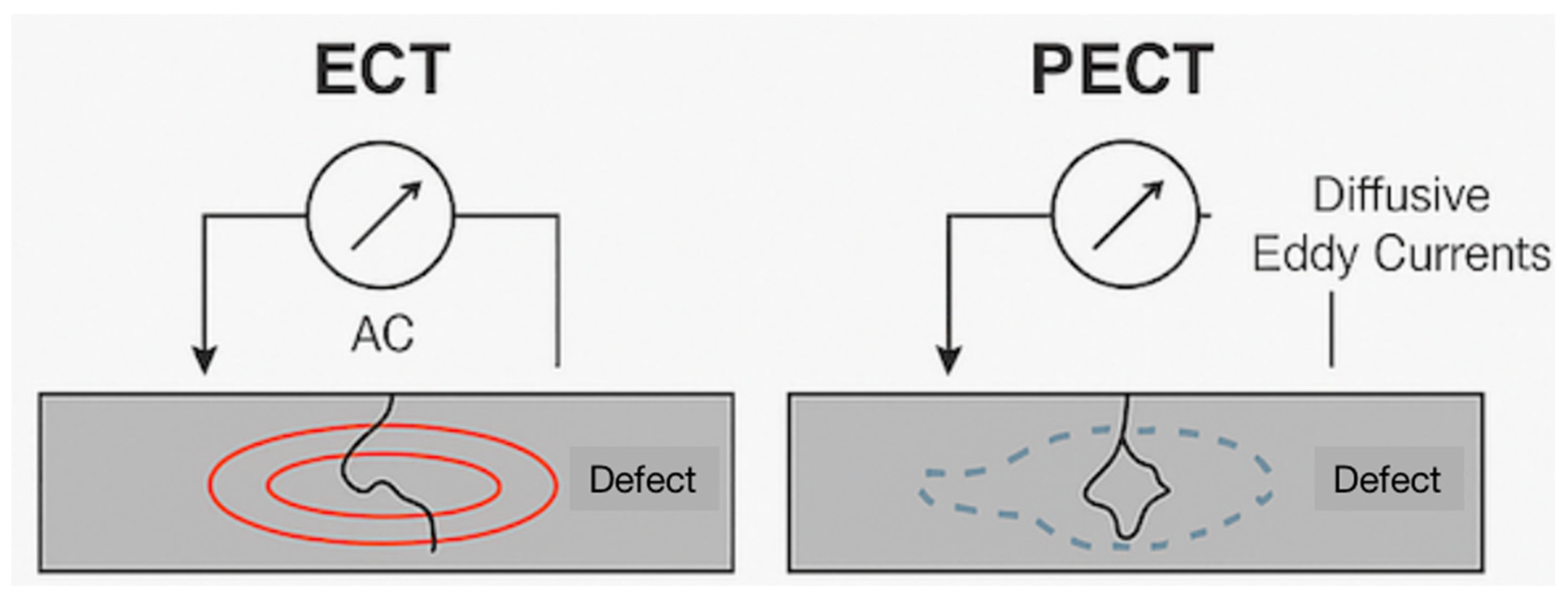


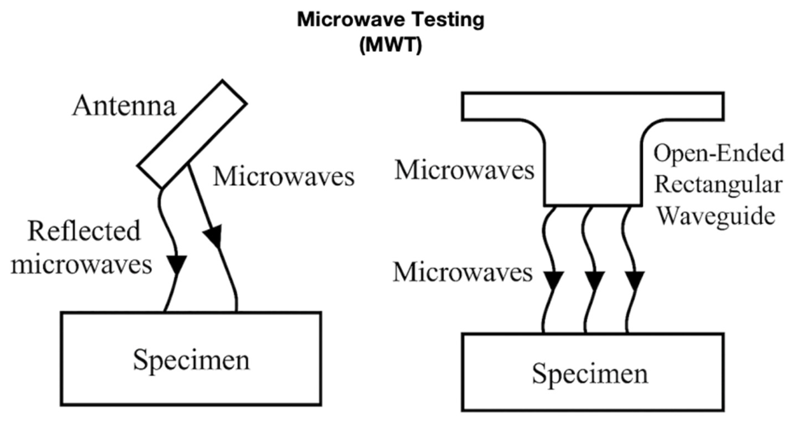
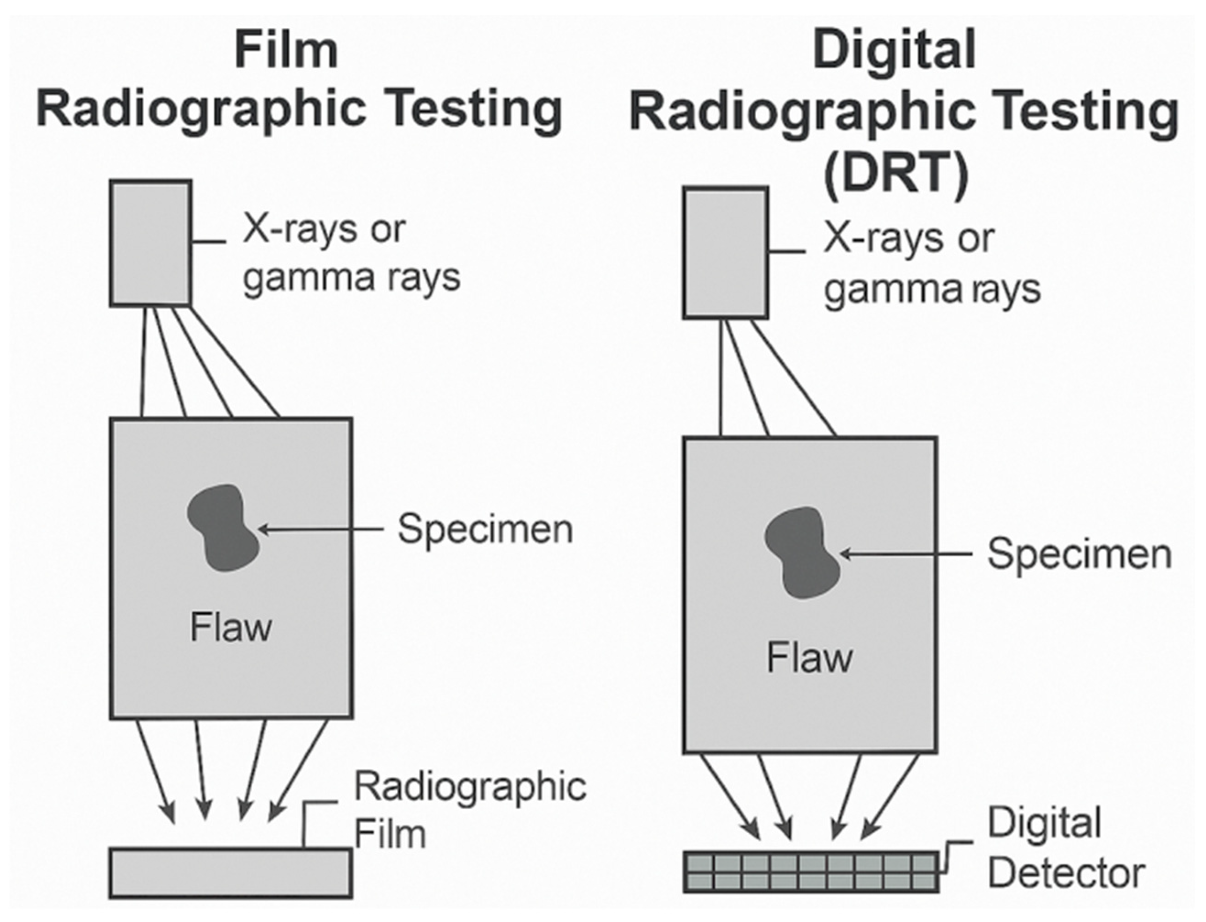
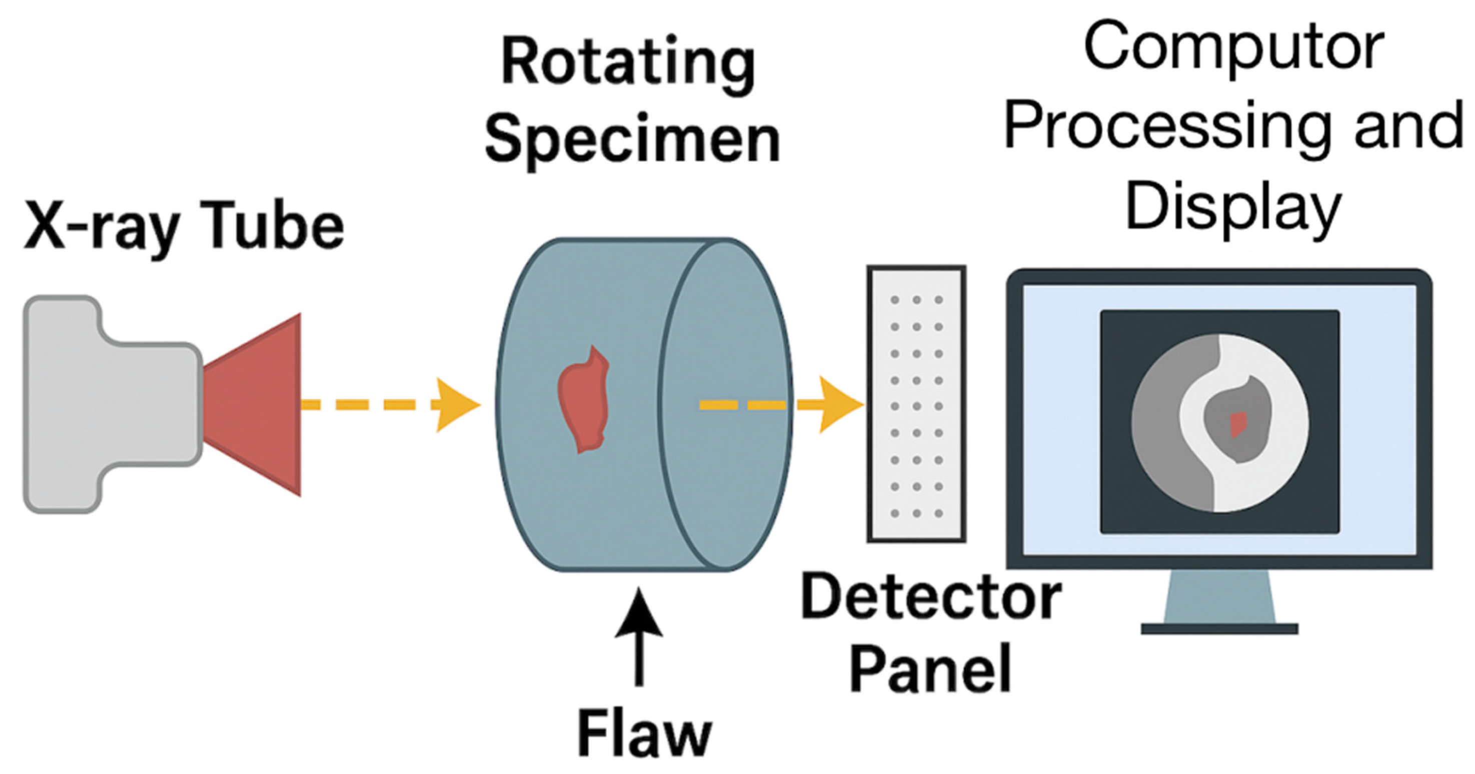


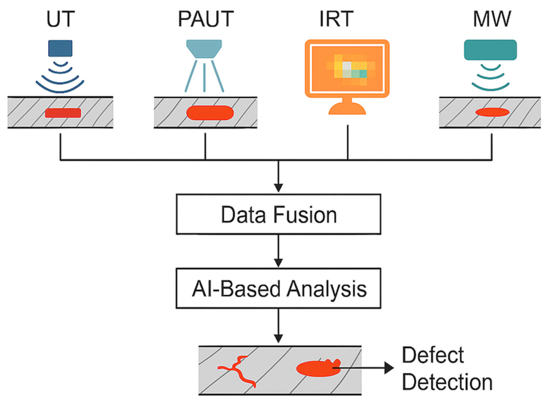
Disclaimer/Publisher’s Note: The statements, opinions and data contained in all publications are solely those of the individual author(s) and contributor(s) and not of MDPI and/or the editor(s). MDPI and/or the editor(s) disclaim responsibility for any injury to people or property resulting from any ideas, methods, instructions or products referred to in the content. |
© 2025 by the authors. Licensee MDPI, Basel, Switzerland. This article is an open access article distributed under the terms and conditions of the Creative Commons Attribution (CC BY) license (https://creativecommons.org/licenses/by/4.0/).