1. Introduction
Drilling is a manufacturing operation used to create circular holes in a workpiece, most commonly using a rotating cutting tool, the drill bit [
1,
2]. Kurt et al. [
3] introduced various drilling processes commonly used in the aerospace and automotive industries, including electron beam machining, ultrasonic machining, electrochemical machining, and abrasive jet machining. Despite advancements in non-traditional methods, conventional drilling remains one of the most widely used machining processes [
4,
5,
6]. Rui et al. [
7] further emphasized its significant economic importance, as drilling is typically one of the final steps in the production of mechanical components, a point also supported by other studies [
8,
9]. In the drilling process, tool geometry and plastic deformation introduce significant complexity [
1]. During drilling, the cutting speed near the center of the drill approaches zero, while both the cutting speed and rake angle vary with distance from the tool’s center (axis). The cutting edge reaches the highest speed, known as the peripheral cutting speed at the major diameter [
1]. Due to these variations, material removal occurs primarily through extrusion. Roteberg et al. [
10] found that the drilling process begins at the point of contact between the tool tip and the workpiece, progressing through a penetration phase until full hole formation is achieved. Guibert et al. [
11] highlighted that drilling deep, small-diameter holes presents challenges in chip evacuation, often resulting in frequent tool failures and poor hole quality. Typically, cutting tools feature two main edges: the cutting edge and the chisel edge. The removed material undergoes significant plastic deformation due to the indentation and rotation of the chisel edge. Based on experimental findings, Rivero et al. [
12] reported that plastic deformation within the shear zone and friction between the tool and the removed material are key sources of heat generation during drilling.
Tsao and Hocheng [
13] demonstrated that revolution feed and tool diameter are the most significant factors influencing feed force, while revolution feed and spindle speed have the greatest impact on surface roughness. Heinemann et al. [
14] stated that despite extensive research, drilling remains one of the most challenging machining operations, which is also confirmed by many researchers nowadays [
15,
16,
17,
18]. A major issue in the drilling process is chip entrapment within the tool’s flutes, which increases friction between the tool and the workpiece and can ultimately lead to a sudden and significant rise in torque [
19]. In this context, chip size and shape are influenced by a combination of workpiece material and cutting tool geometry and cutting conditions [
20,
21,
22,
23]. Bakkal et al. [
24] identified eight fundamental chip formation types based on experimental research. Additionally, the method of chip evacuation from the cutting zone plays a crucial role in determining the final surface quality of the machined hole [
25].
Surface roughness plays a crucial role in drilling, influencing how machined surfaces interact with the rest of the assembly [
26,
27]. It is often a strong predictor of a mechanical component’s performance, as surface irregularities can serve as nucleation sites for cracks or corrosion [
28]. Kilickap [
29] observed that increasing cutting speed and revolution feed generally leads to greater surface roughness, whereas larger point angles under the same cutting conditions resulted in reduced roughness. Rahman et al. [
30] reported that improved drilling performance is associated with lower surface roughness and reduced burr height. They also highlighted that drill diameter, revolution feed, and spindle speed are key factors influencing the final roughness of a drilled hole. As the cutting tool diameter decreases, surface roughness tends to improve, as larger drill diameters remove more material per rotation compared to smaller tools. Kilickap et al. [
31] developed an empirical model to analyse the influence of drilling parameters on surface roughness for machining AISI 1045 steel. Modeling and machine learning techniques were also used in [
32].
The force conditions in the drilling process are primarily determined by the thrust force, which acts in the axial direction. This thrust force, also referred to as the feed force, operates in the direction of the tool’s feed motion and tends to push the cutting tool away from the workpiece. López de Lacalle et al. [
33] stated that feed force and torque result from a combination of two effects: indentation by the chisel edge and material shearing by the main cutting edges. They employed a geometry with a sectioned cutting edge: The secondary cutting edge, formed at the intersection of two lateral surfaces, serves to separate the main cutting edges, enhancing the overall rigidity of the cutting tool and preventing fracture. The main cutting edges are defined by the intersection of the tool’s rake face and lateral surfaces. Arul et al. [
34] proposed that feed force can serve as a process indicator to assess the condition of the cutting wedge. Any variation in feed force may indicate changes in the cutting wedge’s state due to deformation, chipping, or other forms of tool wear. Based on experimental results, Basavarajappa et al. [
35] found that an increase in revolution feed leads to a rise in feed force across all spindle speed combinations. Sharman et al. [
36] defined that as drilling depth increases, torque also rises, accompanied by higher cutting temperatures and increased tool wear. To prevent excessive tool wear and reduce the risk of tool fracture, controlling the cutting (torque) force becomes essential. Jayabal et al. [
37] analysed feed force and torque using a full factorial design and reached the same conclusion—revolution feed is the most significant factor influencing feed force and torque. In contrast, drill diameter and cutting speed were found to have an insignificant effect on changes in the feed force component and torque. Singh et al. [
38] utilized an artificial neural network to analyse the influence of the feed force component and torque on tool wear progression. Their findings indicate that a larger drill diameter and higher revolution feed lead to increased torque values, whereas a combination of higher spindle speeds and larger drill diameters reduces torque. Conversely, a larger cutting tool diameter combined with lower spindle speeds results in higher feed force values. Young et al. [
39] identified drilling depth and revolution feed as the key factors determining torque magnitude. When the drilling depth exceeded five times the tool diameter, a significant increase in torque was observed. This rise in torque elevates tool temperatures in the cutting zone, accelerating tool wear and increasing the risk of tool breakage. Torque is a critical factor influencing machining time, either increasing or decreasing it depending on the cutting conditions. Tsao [
40] developed a mathematical model for predicting feed force based on revolution feed, spindle speed, and tool diameter. Additionally, the cutting edge plays a crucial role in increasing feed force. According to Lin [
41], curvature of the cutting edge reduces both the feed force component and torque values.
Most researchers [
42,
43,
44] have focused on predicting the feed force component and torque based on variations in cutting speed and tool diameter, primarily because changes in torque can be used to monitor and control tool damage and wear. This study aimed to determine experimentally, using the Design of Experiments methodology [
45], the contribution of key technological and selected tool factors to torque variation during the drilling of two structural steels, C45 and 16MnCr5. Additionally, it aimed to examine the influence of the workpiece material on torque variation. To gain deeper insight into the effects of these factors and their interactions, experimentally acquired data were analysed using decision regression trees, a machine learning technique [
46,
47].
Machine learning (ML) and artificial intelligence tools (AIT) are relatively little used in classical drilling processes (mechanical engineering practice). The situation is different in the research of drilling processes in petroleum engineering [
48], or in rock drilling, where there are a relatively large number of review and research studies [
49]. Despite the lack of relevant literature, we perceive an increased interest in machine learning algorithms in drilling aluminum alloys [
50] for predicting the downforce, aluminum composites [
51]. While many studies have analyzed process parameters (forces, torque) in steel drilling using classical methods, the authors present an original approach using ML techniques to analyze the same problem, thereby simultaneously addressing a gap in current research in the field. Extensive experimental work, statistical validation, and implementation of decision trees allowed for a comprehensive and at the same time more detailed analysis of the complex interactions of drilling parameters and their impact on the response (torque). This is the novelty and contribution of the article. On the other hand, we would like to emphasize that the main goal of the article was not the application of the principles of machine learning and artificial intelligence (beyond the framework of traditional statistical methods), but rather a deeper analysis of the drilling process itself.
3. Results and Discussion
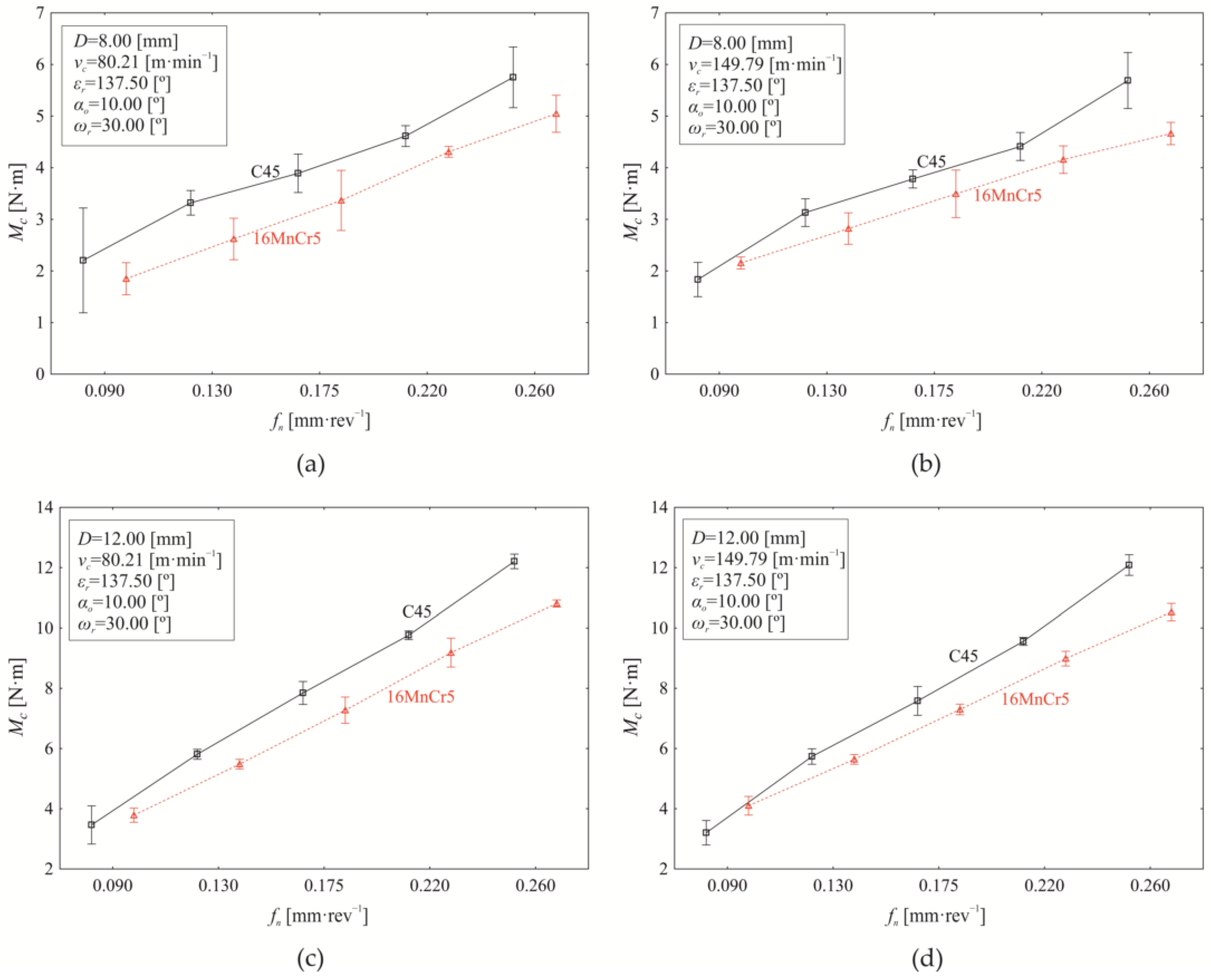
Machining processes generally are multi-factorial stochastic processes, where the individual factors of the machine-tool-workpiece-fixture system are further influenced by the technological conditions of machining. Moreover, the input factors do not act solely as main effects but also exhibit significant mutual interactions. The variation in the examined response (torque
Mc) as a function of revolution feed (
fn) when setting constant values of
εr = 137.50°,
αo = 10.00°,
ωr = 30.00° while simultaneously varying the nominal tool diameter (
D) and cutting speed (
vc) for both investigated materials (C45, 16MnCr5) is presented in
Figure 8.
As shown in
Figure 8, increasing the revolution feed generally leads to a corresponding increase in torque (
Mc). At a nominal tool diameter of
D = 8.00 mm and a cutting speed of
vc = 80.21 m·min
−1, see
Figure 8a, the material’s influence on torque variation is 4.520%. Since machining processes are inherently stochastic, and every measurement is subject to errors (gross, systematic, and random), mathematical statistical tools were used to ensure the accuracy of the results and the reliability of the conclusions drawn.
The influence of machined material (4.520%) on torque variation under the experimental conditions shown in
Figure 8a is statistically significant (
p < 0.000) at the chosen significance level of α = 0.05. The dominant factor affecting torque variation (
Figure 8a) is revolution feed, accounting for 91.450% of the effect (
p < 0.000). Although relatively small (0.470%), the interaction between revolution feed and material also has a statistically significant effect on the measured response (
Mc) (
p = 0.023). Additionally,
Figure 8a indicates that the mean torque during drilling of C45 steel (3.956 ± 0.352 Nm) is higher than that of 16MnCr5 steel (3.437 ± 0.332 Nm) across the tested revolution feed (
fn) range. The difference in mean torque values between S45 and 16MnCr5 is 0.519 ± 0.096 Nm as evaluated using Scheffé’s test significant (
p < 0.000). However, the revolution feed affects the difference in mean torque values between drilling C45 and 16MnCr5 (
Figure 8a), making it statistically significant only at revolution feeds of 0.130 mm·rev
−1 (
p < 0.000), 0.175 mm·rev
−1 (
p = 0.001), and 0.260 mm·rev
−1 (
p < 0.000).
Increasing the cutting speed to
vc = 149.79 m·min
−1 while maintaining
D = 8.00 mm (
Figure 8b) reduces the influence of the material on the torque to 1.900% (
p < 0.000). In contrast, the effect of the revolution feed slightly increases to 92.720% (
p < 0.000), while the interaction between revolution feed and material shows a significant rise to 3.580% (
p < 0.000) compared to the conditions listed in
Figure 8a. The difference in mean torque values (0.311 ± 0.064 Nm) between drilling C45 steel (3.769 ± 0.372 Nm) and 16MnCr5 steel (3.458 ± 0.261 Nm) is statistically significant (
p < 0.000) when setting factors at levels presented in
Figure 8b; the dominant influence of the revolution feed is again evident. Significant differences in mean torque (between C45 and 16MnCr5) are observed at
fn of 0.090 mm·rev
−1 (−0.321 ± 0.241 Nm,
p < 0.000), at 0.130 mm·rev
−1 (0.309 ± 0.103 Nm,
p < 0.000), and at the upper limit of the experimental range of
fn = 0.260 mm·rev
−1 (1.027 ± 0.136 Nm,
p < 0.000). When using drill of
D = 8.00 mm, increasing the cutting speed from 80.21 m·min
−1 (
Figure 8a) to 149.79 m·min
−1 (
Figure 6b) reduces the mean torque value by 4.948% (
p < 0.000) during machining of C45 steel. In contrast, for 16MnCr5 steel, the torque value shows a slight increase of 0.599%, which is not statistically significant (
p = 0.968).
When setting drilling conditions as listed in
Figure 8c, with increasing the nominal drill diameter to
D = 12.00 mm (at
vc = 80.21 m·min
−1), the material effect on torque (
Mc) reduces to 0.83% (
p < 0.000), the revolution feed effect on
Mc increases to 97.860% (
p < 0.000), while the effect of their interaction (material and revolution feed) rises to 0.970% (
p < 0.000). Moreover, increasing the drill diameter
D from 8 mm to 12.00 mm at a cutting speed of 80.21 m·min
−1 leads to an increase in mean torque by 97.559% for C45 steel (by 112.598% for 16MnCr5 steel). Significant differences in
Mc mean values between C45 and 16MnCr5 were observed at revolution feeds higher than 0.090 mm·rev
−1; specifically, at 0.130 mm·rev
−1 (0.327 ± 0.058 Nm,
p < 0.000), 0.175 mm·rev
−1 (0.572 ± 0.146 Nm,
p < 0.000), 0.220 mm·rev
−1 (0.579 ± 0.111 Nm,
p < 0.000), and 0.260 mm·rev
−1 (1.398 ± 0.065 Nm,
p < 0.000).
On increasing the cutting speed
vc to 149.79 m·min
−1 when using drill of D = 12.00 mm (
Figure 8d), the material effect on torque variation reduces to 0.350% (
p < 0.000), while the contribution of revolution feed to the measured response (
Mc) remains dominant at 97.240% (
p < 0.000). At the same time, the influence of interaction (material and revolution feed) increases to 2.130% (
p < 0.000) compared to the conditions in
Figure 8c. Comparison analysis of
Mc mean values (
Figure 8c,d), while setting constant drill diameter (
D = 12.00 mm) and varying cutting speed (
vc = 80.21 m·min
−1,
vc = 149.79 m·min
−1), indicates that increasing the cutting speed
vc decreases the mean torque value by 2.424% (
p < 0.000) for C45 steel. On the other hand, the mean torque value increases slightly by 0.053% (
p = 0.999) with increasing of
vc for 16MnCr5 steel, but it is not statistically significant.
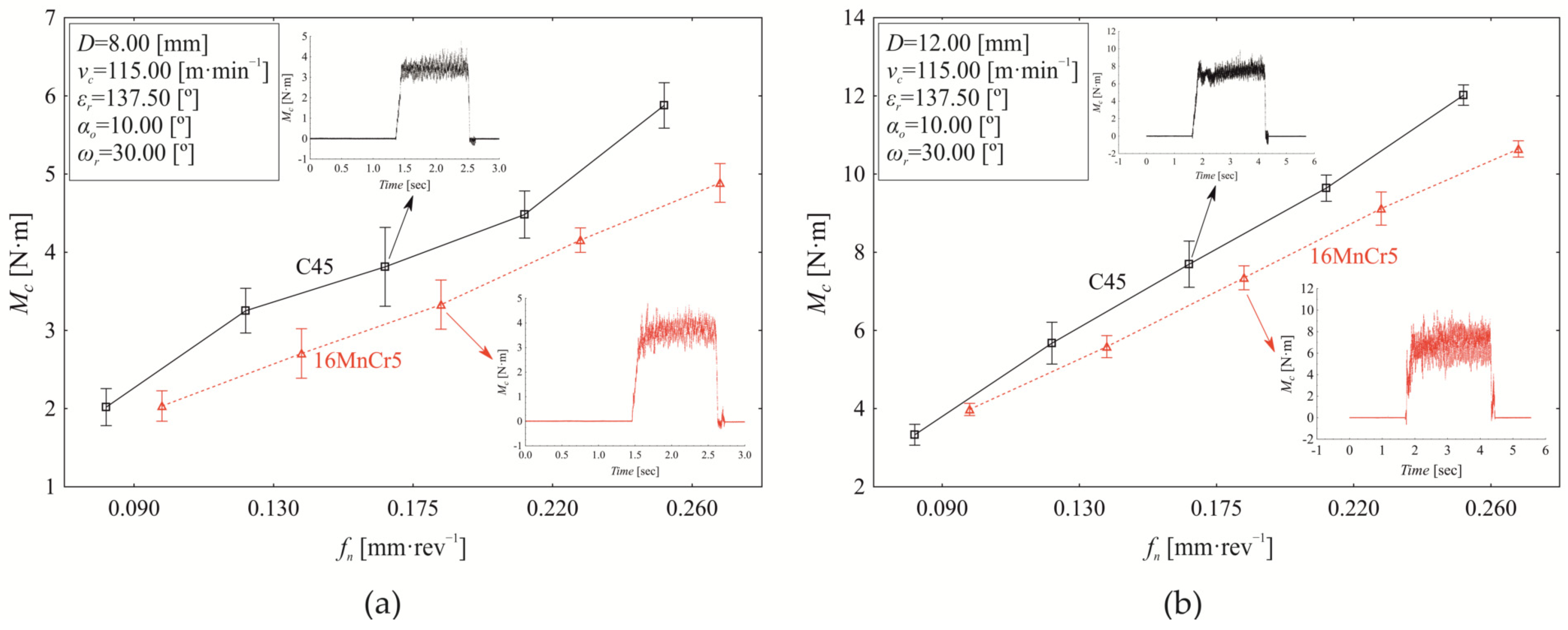
In the torque analysis presented in
Figure 8, we focused on the boundary values of the selected controlled technological (cutting speed) and tool-related (nominal tool diameter) factors while varying the revolution feed. Since the analysis confirmed a significant influence of revolution feed, material, and their interaction on torque variation at the selected boundary points (
vc,
D), we aim to refine the analysis further. This will be done by examining the mean cutting speed values at a nominal drill diameter
D = 8.00 mm (
Figure 9a) and at the upper limit of the tested interval,
D = 12.00 mm (
Figure 9b).
The variation in torque as a function of revolution feed at a cutting speed of
vc = 115.00 m·min
−1 and a nominal tool diameter of
D = 8.00 mm is shown in
Figure 9a. Under these defined technological and tool-related conditions, the influence of material on torque variation is 3.860% (
p < 0.000), the influence of revolution feed is 92.830% (
p < 0.000), and the influence of the interaction between material and revolution feed is 1.890% (
p < 0.000). Differences in mean torque values between drilling C45 and 16MnCr5 vary depending on the applied revolution feed. Statistically significant differences in mean torque values were observed at revolution feeds as follows:
fn = 0.130 mm·rev−
1 (0.547 ± 0.108 Nm,
p < 0.000);
fn = 0.175 mm·rev
−1 (0.483 ± 0.146 Nm,
p < 0.000);
fn = 0.220 mm·rev
−1 (0.326 ± 0.082 Nm,
p < 0.000); and
fn = 0.260 mm·rev
−1 (0.991 ± 0.096 Nm,
p < 0.000). Increasing the nominal drill diameter from 8.00 mm (
Figure 9a) to
D = 12.00 mm at cutting speed
vc = 115.00 m·min
−1 (
Figure 9b) results in a 97.276% increase in torque
Mc for C45 steel and 113.074% for 16MnCr5 steel. At this tool diameter (12.00 mm,
Figure 9b), the influence of material on torque variation is 0.380% (
p < 0.000), while the revolution feed contributes 97.780% (
p < 0.000), and the interaction between material and revolution feed accounts for 1.440% (
p < 0.000). When considering the combined effect of changing the nominal tool diameter (comparing
Figure 9a,b), the overall influence of material on the torque variation is 0.500% (
p < 0.000), while the revolution feed contributes 45.360% (
p < 0.000), and the nominal tool diameter accounts for 45.480% (
p < 0.000). These results highlight that the contribution of technological and tool-related factors to torque variation is strongly dependent on their specific values.
The variation in torque as a function of revolution feed at the mean cutting speed (
vc = 115.00 m·min
−1) and mean nominal tool diameter (
D = 10.00 mm) is shown in
Figure 10a,b. The contribution of material to torque variation is 1.150% (
p < 0.000), while revolution feed accounts for 97.010% (
p < 0.000), and the interaction between material and revolution feed contributes 1.190% (
p < 0.000). The mean difference in torque values between drilling C45 steel (5.826 ± 0.611 Nm) and 16MnCr5 steel (5.406 ± 0.502 Nm) is 0.420 ± 0.278 Nm (
p < 0.000). Additionally, significant differences in torque values were observed between C45 and 16MnCr5 at all applied revolution feed values.
In the following section, the influence of selected tool factors (
D,
εᵣ,
ωᵣ) on torque variation (
Mc) is analysed. As seen in
Figure 11, a constant cutting speed of 115.00 m·min
−1 and a revolution feed of 0.175 mm·rev
−1 were maintained across all experimental trials, the nominal drill diameter (
D) was used as the independent, controlled tool factor.
Based on the analysis presented in
Figure 11, the experimental results demonstrate that increasing the nominal tool diameter (
D) leads to a corresponding increase in torque (
Mc). A statistically significant material effect on the torque is observed at the point angle of
εᵣ = 130.00° and helix angle of
ωᵣ = 25.0° (
Figure 11a); its value represents 1.480% at the chosen significance level of α = 0.05. The dominant factor affecting torque variation is the nominal tool diameter (
D), contributing 97.090% (
p < 0.000). Additionally, the interaction of material and tool diameter has a statistically significant effect (
p < 0.000), accounting for 0.520% of the variation. When analysing only the mean torque values for the tested materials, independent of tool diameter, the difference in mean torque (
Mc) between C45 steel (5.674 ± 0.399 Nm) and 16MnCr5 steel (6.041 ± 0.457 Nm) is statistically significant (
p < 0.000) based on Scheffé’s test. However, when considering the effect of nominal tool diameter (
D), significant differences in torque values appear only at tool diameters of 10.00 mm and above. At
D = 10.00 mm, the statistical difference in mean torque between C45 (5.627 ± 0.127 Nm) and 16MnCr5 (6.120 ± 0.189 Nm) is −0.493 ± 0.158 Nm, and is statistically significant,
p < 0.000). This trend is also observed for
D = 11.10 mm (−0.417 ± 0.113 Nm,
p < 0.000), and
D = 12.00 mm (−0.660 ± 0.087 Nm,
p < 0.000). With the increase of the point angle to
εᵣ = 145.10° while maintaining a helix angle of
ωᵣ = 25.0° (
Figure 11b), the influence of material on torque variation decreases to 0.700%, compared to
Figure 11a. At the same time, the influence of nominal tool diameter increases to 97.580%, while the interaction effect between material and tool diameter decreases to 0.490%. With the increase of the point angle to
εᵣ = 145.10° while maintaining the helix angle at
ωᵣ = 25.0° (
Figure 11b compared to
Figure 11a), the material effect on
Mc decreases to 0.700%, nominal tool diameter increases to 97.580%, while the interaction effect (material and drill diameter) decreases to 0.490%.
All evaluated input factors demonstrate a statistically significant effect on torque
Mc (
p < 0.000). However, significant differences in mean torque values (
p < 0.000) between C45 steel (
Mc = 6.217 ± 0.142 Nm) and 16MnCr5 steel (
Mc = 0.373 ± 0.222 Nm) during drilling at a point angle of
εr = 145.10° appear only at a nominal tool diameter of
D = 11.10 mm (resulting torque difference is 0.373 ± 0.222 Nm). At a nominal tool diameter of
D = 12.00 mm, the resulting torque difference is 0.470 ± 0.090 Nm when comparing
Mc during drilling steel C45 (
Mc = 7.014 ± 0.090 Nm) and steel 16MnCr5 (6.634 ± 0.089 Nm). Compared to the previous case in
Figure 11a, the torque values are higher during drilling steel C45. Increasing the helix angle to
ωr = 35.0° at a point angle settled at
εr = 130.00° (
Figure 11c), the material effect on torque variation increases to 6.040% (
p < 0.000), the drill diameter effect decreases to 92.690% (
p < 0.000), and the influence of interaction “material and tool diameter” increases slightly to 0.510% (
p < 0.000). The difference in mean torque values between C45 and 16MnCr5 steel increases with the nominal tool diameter, ranging from −0.476 ± 0.066 Nm at
D = 8.00 mm to −1.080 ± 0.099 Nm at
D = 12.00 mm. It is important to note that all differences in mean torque values for all tested nominal tool diameters are statistically significant (
p < 0.000). Additionally, torque values during C45 drilling remain lower than those for 16MnCr5 drilling across all cases. Changing the point angle to
εr =145.10° while maintaining a helix angle of
ωr = 35.0° (
Figure 11d) results in a decrease in the influence of material on the torque variation to 0.160%. At the same time, the influence of the nominal tool diameter increases to 98.37%, while the influence of the interaction between material and tool diameter decreases to 0.430%. All contributing factors significantly affect torque variation (
p < 0.000). However, significant differences in mean torque values between C45 steel and 16MnCr5 steel are observed only at a nominal tool diameter of D = 8.00 mm, with a difference of −0.377 ± 0.077 Nm.
Taking into account all partial experiments carried out under conditions shown in
Figure 11, while keeping constant revolution feed and cutting speed (
fn = 0.175 mm·rev
−1,
vc = 115.00 m·min
−1), the nominal tool diameter
D is observed to be the most influential factor (87.390% share of influence in the torque variation,
p < 0.000). The second most significant controlled factor is the point angle, contributing 6.470% (
p < 0.000), followed by the helix angle with an impact of 2.110% (
p < 0.000). Although material as a main effect contributes only 0.740% to torque variation, its influence remains statistically significant (
p < 0.000). Additionally, several interaction effects significantly influence torque variation (
p < 0.000), including material and point angle (1.090%), material and helix angle (0.360%), nominal tool diameter and point angle (0.480%), and the combined interaction of material, nominal tool diameter, and point angle (0.420%). For the first significant interaction (material and point angle), a statistically significant difference in mean torque values between C45 steel and 16MnCr5 steel is observed only at
εr = 130.00°, with a difference of −0.564 ± 0.302 Nm (
p < 0.000). Regarding the second significant interaction (material and helix angle), statistically significant differences in mean torque values between C45 steel and 16MnCr5 steel are present at both tested helix angles. At
ωr = 25.0°, the difference in mean torque values is −0.076 ± 0.021 Nm (
p = 0.004), while at
ωr = 35.0°, it increases to −0.433 ± 0.024 Nm (
p < 0.000).
The graphical outputs of analysis of experiments carried out at the borderline factor levels (
Table 2) at constant
fn = 0.175 mm·rev
−1 and
vc = 115.00 m·min
−1 are shown in
Figure 12. The experimental results demonstrate that increasing the nominal tool diameter (
D) leads to a corresponding increase in torque (
Mc).
At a helix angle of
ωᵣ = 30.0° and a point angle of
εᵣ = 130.00° (
Figure 12a), material accounts for 0.560% of the variation in torque, while the nominal tool diameter contributes 98.450%. The interaction between material and tool diameter has a minor yet statistically significant influence of 0.90% (
p < 0.000). Statistically significant differences in torque (
p < 0.000) between C45 and 16MnCr5 begin to emerge at a nominal tool diameter of
D = 10.00 mm, with a torque difference of −0.196 ± 0.051 Nm. As the nominal tool diameter increases to
D = 11.10 mm, the difference grows to -0.380 ± 0.073 Nm, reaching −0.557 ± 0.081 Nm at the upper limit of the tested range (
D = 12.00 mm). Lower values of
Mc are achieved when drilling C45 material compared to steel 16MnCr5. With the increase of point angle at
εr = 137.50° (
Figure 12b), the material effect conditionally increases to 2.100% (
p < 0.000), and the drill diameter effect decreases to 97.580%. As seen in
Figure 12b, the influence of “material and drill diameter” interaction is not observed to be significant (
p = 0.141). When comparing
Mc values at experimental conditions defined in
Figure 12a,b, there is a significant difference (
p < 0.000) in the mean torque values (0.193 ± 0.020 Nm). It can be stated that increasing the point angle by 5.769% will result in a reduction of the conditional
Mc value by 3.358%, but this conclusion applies only to the conditions shown in
Figure 12. The main effect of
εr on
Mc values represents 0.440% (
p < 0.000). Significant interactions were observed as follows: point angle and material (1.440%), point angle and tool diameter (0.130%), and point angle and material and tool diameter (0.110%).
The extension analysis of torque dependence on the tool diameter is shown in
Figure 13; the point angle is increased to the level of
εr = 145.10°. At this point angle, we can observe a significant effect of material on torque variation (2.450%,
p < 0.000); the significant tool diameter effect contributes 96.210% (
p < 0.000). Additionally, the interaction “material and tool diameter” accounts for 0.770% (
p < 0.000). When considering the combined conditions from
Figure 10a,b and
Figure 11a, which represent the effect of the point angle in the range of
εr = 130.00° to 145.10° while keeping
ωr = 30.0°,
fn = 0.175 mm·rev
−1, and
vn = 115.00 m·min
−1 constant, the influence of the point angle on torque variation is 4.440% (
p < 0.000). In this case, the influence of material decreases to 0.460%, while statistically significant interactions emerge between point angle and material (1.060%) and between point angle and nominal tool diameter (0.280%). When setting constant values of
ωr = 30.0°,
fn = 0.175 mm·rev
−1,
vc = 115.00 m·min
−1, while simultaneously increasing point angle
εr within the interval from
εr = 130.00° to 145.10° (
Figure 12 and
Figure 13a), the effect of the point angle (
εr) on the Mc torque variation represents 4.440% (
p < 0.000). In this case, the influence of material decreases to 0.460%, while statistically significant interactions emerge between point angle and material (1.060%) and between point angle and nominal tool diameter (0.280%).
Under drilling conditions at level 4, as defined in
Table 2, the nominal tool diameter is the only statistically significant factor (
p < 0.000) influencing torque variation (99.730%). As the nominal tool diameter increases, the mean torque value rises, ranging from 4.237 ± 0.029 Nm at
D = 8.00 mm to 9.340 ± 0.047 Nm at
D = 12.00 mm. According to the conditions in
Figure 13a, an increase of 0.10 mm in nominal tool diameter results in a 3.011% rise in relative torque value.
The presented analyses highlight an important aspect—the complexity of the drilling process. Its evaluation must consider not only the influence of the material but also the combined effects of tool and technological factors on torque variation. This influence is highly dependent on the specific values of input variables while also being significantly affected by their interactions, which play a crucial role in determining the overall torque behaviour. A comprehensive evaluation of the experiment, which consisted of 1500 individual trials focusing on the influence of selected tool and technological factors on torque variation (Mc), leads to the conclusion that the overall effect of material on torque variation is 1.430%. Although this influence is relatively low, it remains statistically significant (p < 0.000) at a significance level of α = 0.05. This indicates that despite its minor contribution, the material must be considered in the torque analysis. The dominant factor affecting torque variation is the nominal tool diameter, contributing 53.552% (p < 0.000), followed by the feed rate, which accounts for 36.263% (p < 0.000). Among the other tool-related factors, the point angle influences torque variation by 1.189% (p < 0.000), while the helix angle contributes 0.310% (p < 0.000). The effect of cutting speed on torque variation was not confirmed (p = 0.354) in this analysis.
The differences between C45 steel and 16MnCr5 steel can be observed in the percentage contribution of tool and technological factors to torque variation. For C45 steel, the nominal tool diameter (
D) contributes 50.115% (
p < 0.000) to torque variation, while the feed rate (
fn) accounts for 41.603% (
p < 0.000). The point angle influences torque variation by 0.486% (
p < 0.000), and the helix angle contributes 0.680% (p < 0.000). For 16MnCr5 steel, the influence of nominal tool diameter increases to 60.373% (
p < 0.000), while the contribution of feed rate decreases to 31.480% (
p < 0.000) compared to C45. Simultaneously, the effect of point angle increases to 2.562% (
p < 0.000). The helix angle has a minor influence on torque variation for 16MnCr5, accounting for 0.098% (
p = 0.002). For both materials, the cutting speed does not have a statistically significant effect on torque variation. The influence of the two most significant factors, nominal tool diameter (
D) and feed rate (
fn), on torque variation in C45 and 16MnCr5 drilling is presented in
Figure 14.
Figure 14 illustrates that the torque variation during drilling of C45 and 16MnCr5 steels, as a function of nominal tool diameter and feed rate, follows a similar trend. However, differences are evident in the absolute torque values for each material. Additionally, a gradual shift in the torque dependency on nominal tool diameter and feed rate can be observed. At higher tool diameters and feed rates, the relationship appears linear, whereas at lower feed rates, the dependency becomes highly nonlinear.
Detailed Analysis of Drilling Process Parameters by Decision Tree
The conducted analyses revealed that the influence of selected technological and tool factors on torque variation is complex, further influenced by the machined material. A comprehensive approach is necessary to fully understand this relationship. A detailed analysis of the drilling process, focusing on torque variation, was performed using machine learning, specifically decision trees, with the CERT method [
33] selected for tree construction. Based on experimental measurements, the constructed decision tree achieved an adjusted coefficient of determination of 99.460% (RMSE = 0.1618, MSE = 0.0262, MAD = 0.1201, MAPE = 0.0258) with a total of 118 nodes. The key factor affecting torque variation, with an average torque value of 5.557 ± 0.112 Nm across the dataset, was identified as the nominal tool diameter. Considering the mean values of torque (
Mc), two statistically distinct groups (
p < 0.000) were identified. The first group with nominal tool diameters of D = 8.0 mm and D = 8.9 mm exhibited a mean torque of 3.822 ± 0.077 Nm; the second group with
D ranging from D = 10.0 mm to D = 12.0 mm had a mean torque of 6.779 ± 0.134 Nm.
The following analysis focuses on these two defined groups. At lower nominal tool diameters (8.0 mm and 8.9 mm), the influence of feed rate behaves differently. For low feed rates (0.090 and 0.130 mm·rev−1), the mean torque value is 2.495 ± 0.101 Nm, whereas for feed rates above 0.175 mm·rev−1, the mean torque increases to 4.414 ± 0.065 Nm, with a statistically significant difference (p < 0.000). The effect of material on torque variation becomes apparent at fn = 0.130 mm·rev−1, where the mean torque for drilling 16MnCr5 steel is 2.715 ± 0.070 Nm, and for C45 steel, it reaches 3.233 ± 0.070 Nm, with a statistically significant difference (p < 0.000). At minimum feed rates (fn = 0.090 mm·rev−1), the effect of material varies depending on cutting speed. For cutting speeds between vc = 80.21 and 115.00 m·min−1, the mean torque for drilling 16MnCr5 is 1.940 ± 0.052 Nm, whereas for C45 steel, it is 2.111 ± 0.057 Nm. However, at higher cutting speeds (vc = 134.50 to 149.79 m·min−1), the trend reverses, with mean torque values of 2.155 ± 0.061 Nm for 16MnCr5 and 1.833 ± 0.049 Nm for C45. For feed rates above 0.130 mm·rev−1, the effect of material on torque variation is influenced by the helix angle (ωr), where an increase in ωr leads to a reduction in torque.
In the second group, which includes nominal tool diameters ranging from D = 10.00 to 12.00 mm, torque variation is primarily influenced by feed rate. The feed rates can be categorized into two ranges: fn = 0.090 to 0.175 mm·rev−1, where the mean torque is 5.945 ± 0.084 Nm, and fn = 0.220 to 0.260 mm·rev−1, where the mean torque increases to 9.269 ± 0.173 Nm. At a feed rate of fₙ = 0.090 mm·rev−1, the nominal tool diameter becomes a key factor in torque variation. For D = 10.0 mm and 11.10 mm, the mean torque is 2.871 ± 0.081 Nm, with C45 steel showing a mean torque of 2.711 ± 0.007 Nm and 16MnCr5 steel showing 3.031 ± 0.051 Nm. When the nominal tool diameter increases to D = 12.0 mm, the mean torque rises to 3.332 ± 0.043 Nm for C45 and 3.955 ± 0.073 Nm for 16MnCr5, indicating that torque increases with tool diameter, with a more pronounced effect when drilling 16MnCr5 steel. At feed rates of fn = 0.130 and 0.175 mm·rev−1, nominal tool diameter remains a decisive factor in torque variation, leading to the formation of two distinct groups. The first group consists of tools with D = 10.0 mm, where the effect of material varies depending on the specific feed rate value. At a feed rate of fn = 0.130 mm·rev−1, the mean torque value for C45 steel is 4.599 ± 0.046 Nm, while for 16MnCr5 steel, it is 4.110 ± 0.012 Nm. However, at fn = 0.175 mm·rev−1, the effect of material on torque variation depends on both the point angle (εr) and the helix angle (ωr). When the point angle is εr = 134.50° or 145.10°, an increase in the helix angle leads to a decrease in conditional torque values, with the material effect becoming less pronounced at higher ωr levels. Interestingly, at ωr = 32.80° and 35.00°, the torque value for C45 steel (4.619 ± 0.014 Nm) is lower than that for 16MnCr5 steel (4.729 ± 0.016 Nm), while at ωr = 25.00° and 30.00°, the trend reverses, with C45 showing a higher torque (5.185 ± 0.017 Nm) compared to 16MnCr5 (4.919 ± 0.009 Nm). This confirms the previous observation that increasing the helix angle reduces the torque values. At higher feed rates (fn = 0.220 and 0.260 mm·rev−1), the dominant factor remains the nominal tool diameter (D). For D = 10.00 mm and 11.10 mm, a significant material effect is observed only at fn = 0.260 mm·rev−1, where the mean torque for C45 (8.947 ± 0.111 Nm) is higher than for 16MnCr5 (7.930 ± 0.016 Nm). At a nominal tool diameter of D = 12.00 mm and a feed rate of fn = 0.220 mm·rev−1, there is no significant difference in torque between C45 (9.583 ± 0.177 Nm) and 16MnCr5 (9.149 ± 0.203 Nm). However, at fn = 0.260 mm·rev−1, the mean torque for C45 (12.104 ± 0.156 Nm) is statistically significantly higher than for 16MnCr5 (10.659 ± 0.155 Nm).
The conducted analyses indicate that the influence of selected technological and tool factors on torque variation during drilling is highly complex, requiring a detailed approach to fully understand its behaviour. Additionally, the results confirm that the machined material plays a significant role in torque variation. Although its direct contribution appears relatively small (1.430%), it has a fundamental impact on the way selected input variables interact and influence torque behaviour.


 ,
, 


