
Full-Locked Coil Ropes with HDPE Sheath: Studies of Mechanical Behavior of HDPE Under Accelerated Aging


Abstract
1. Introduction
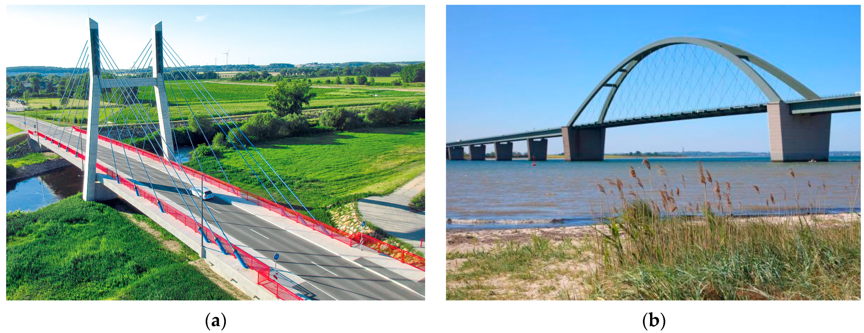
1.1. Bridge Cables
1.1.1. Conventional Bridge Cables
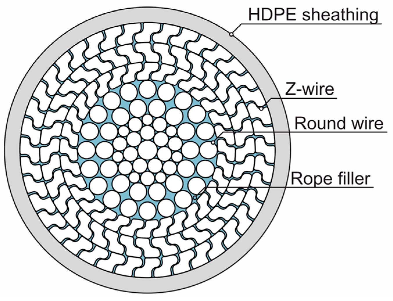
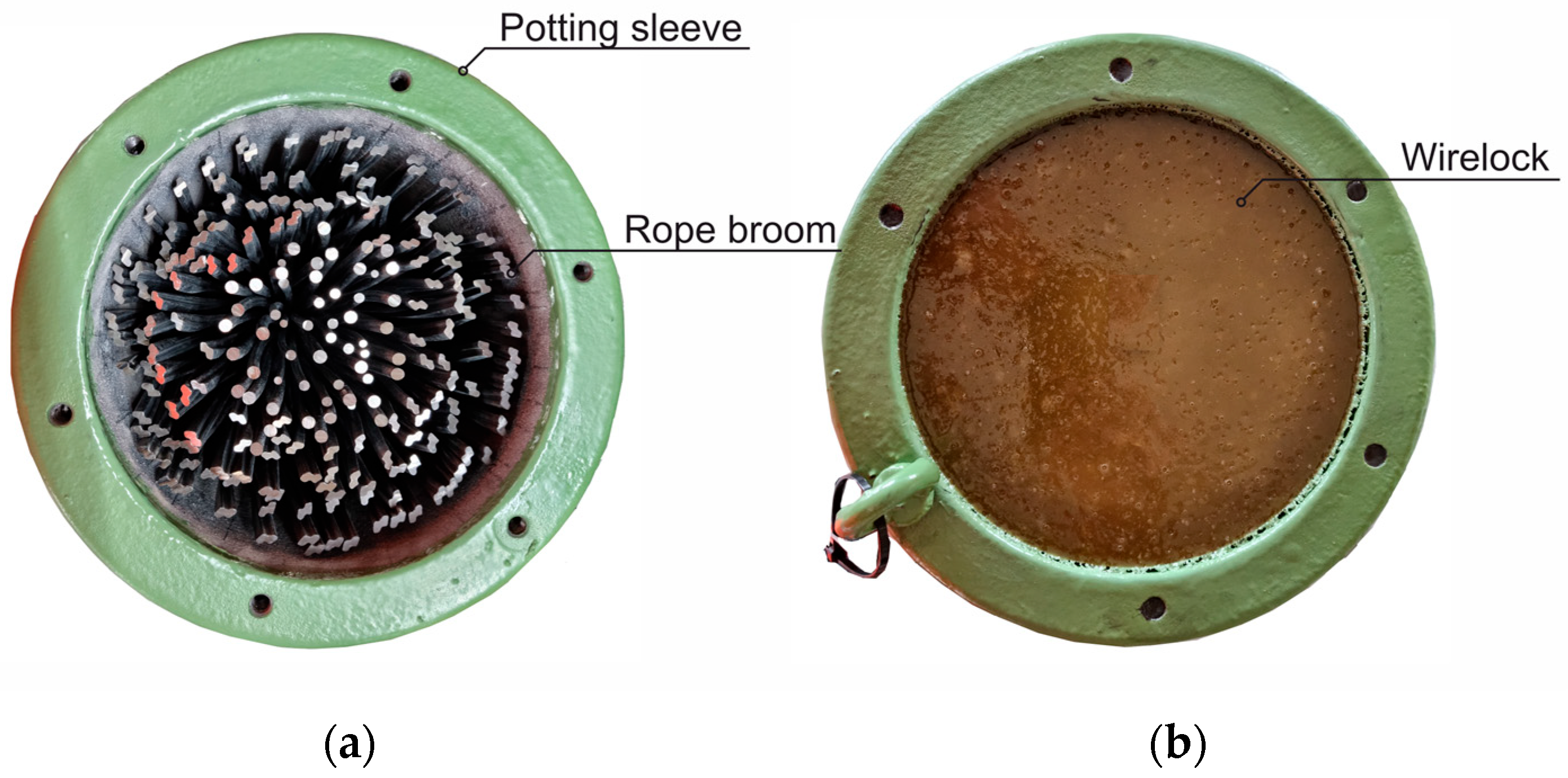
1.1.2. FLCR Sheathed with HDPE
1.2. High-Density Polyethylene
1.2.1. Basic Properties
1.2.2. Resistance of HDPE
2. Materials and Methods
2.1. High-Density Polyethylene
2.2. Accelerated Aging Procedures
2.2.1. Sanding Method
2.2.2. Climatic Boundary Conditions and Compatibility
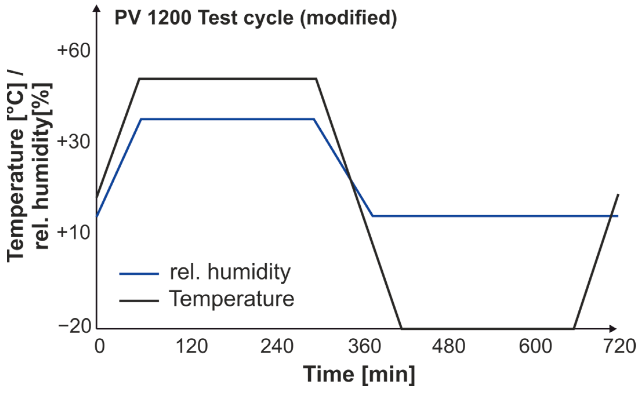
2.2.3. Cyclical Conditioning
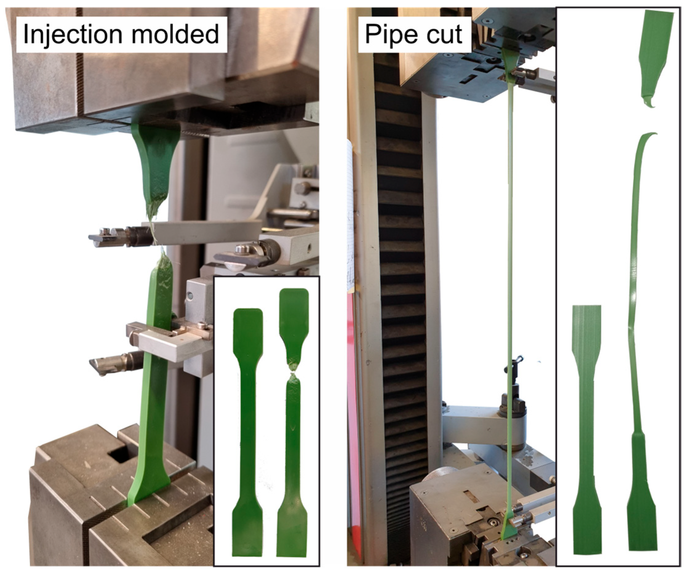
2.3. Sample Manufacturing
2.4. Differential Scanning Calorimetry and Oxidation Induction
3. Results
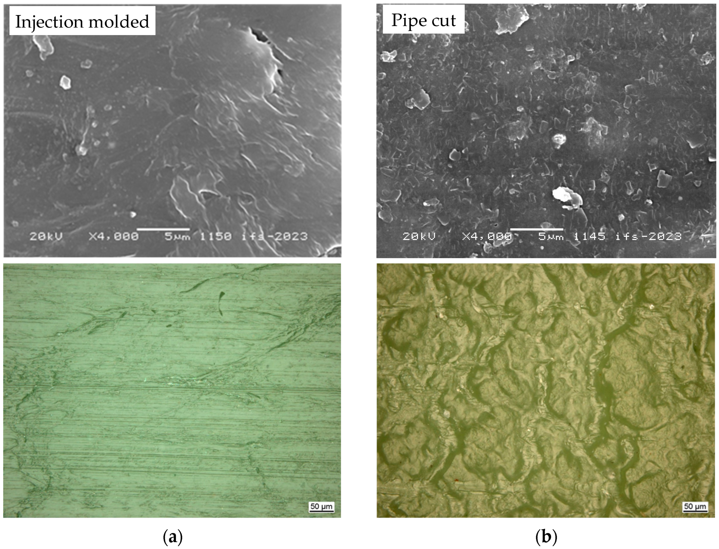
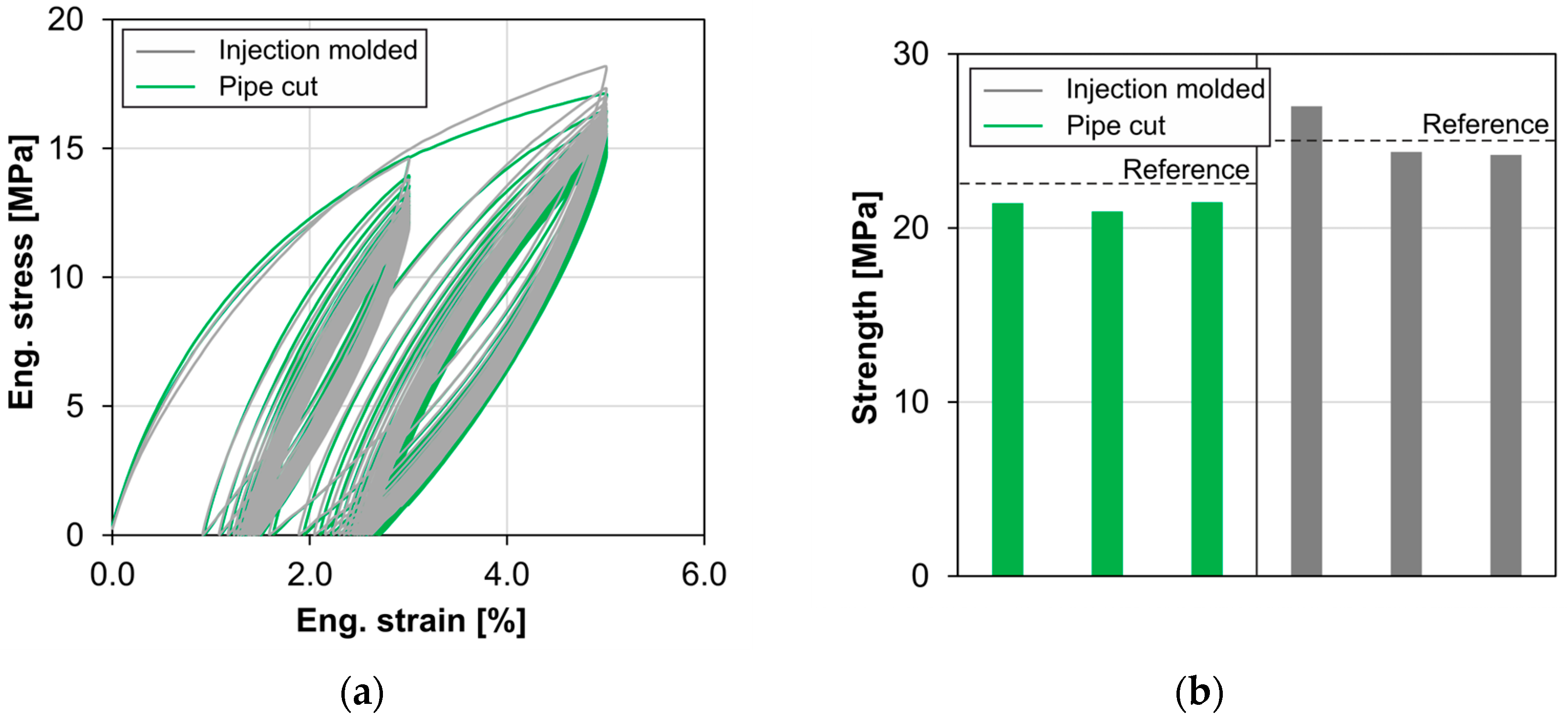
3.1. Mechanical Behavior and Surface Conditions
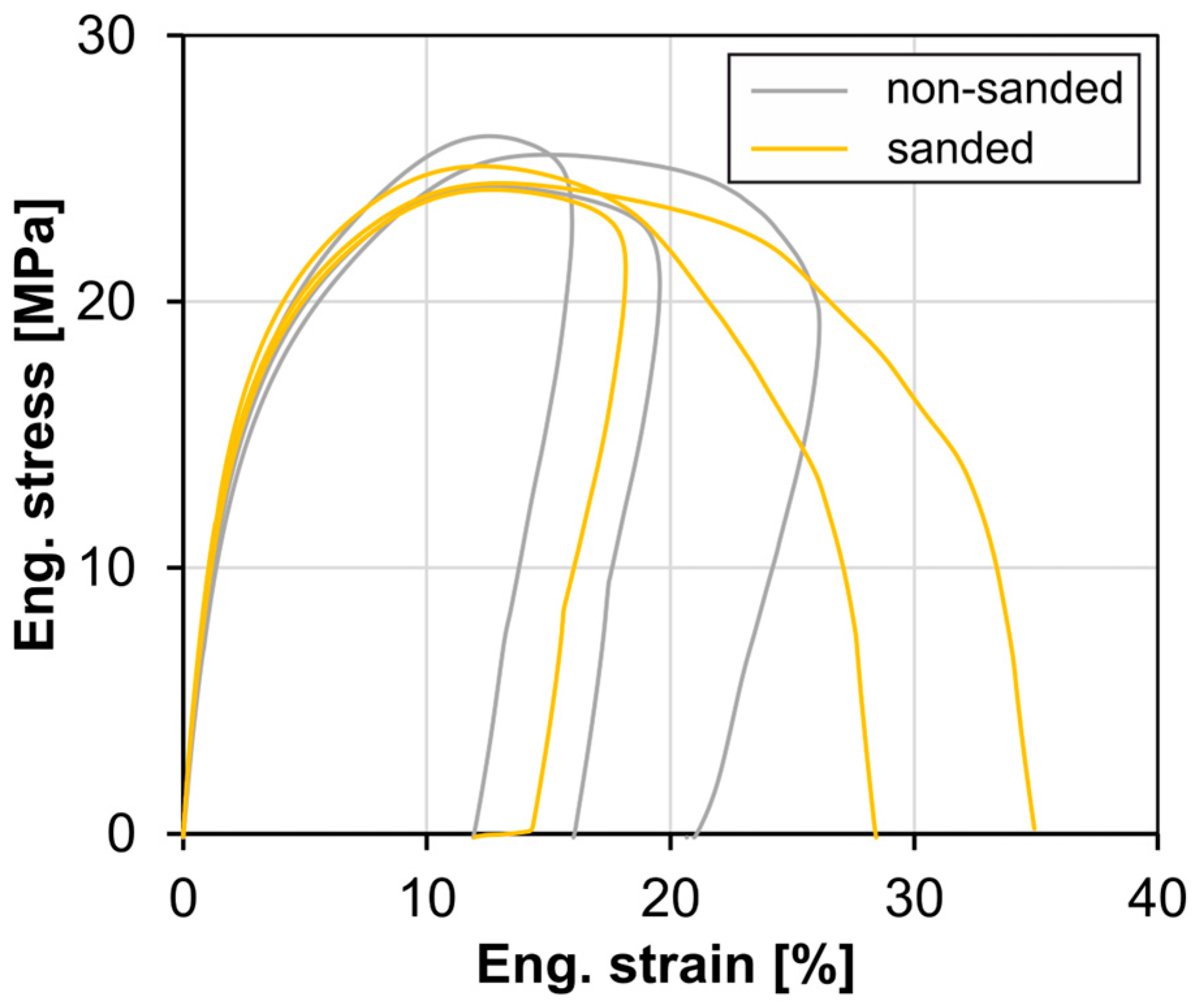
3.2. Sanding Method
3.3. Cyclical Conditioning
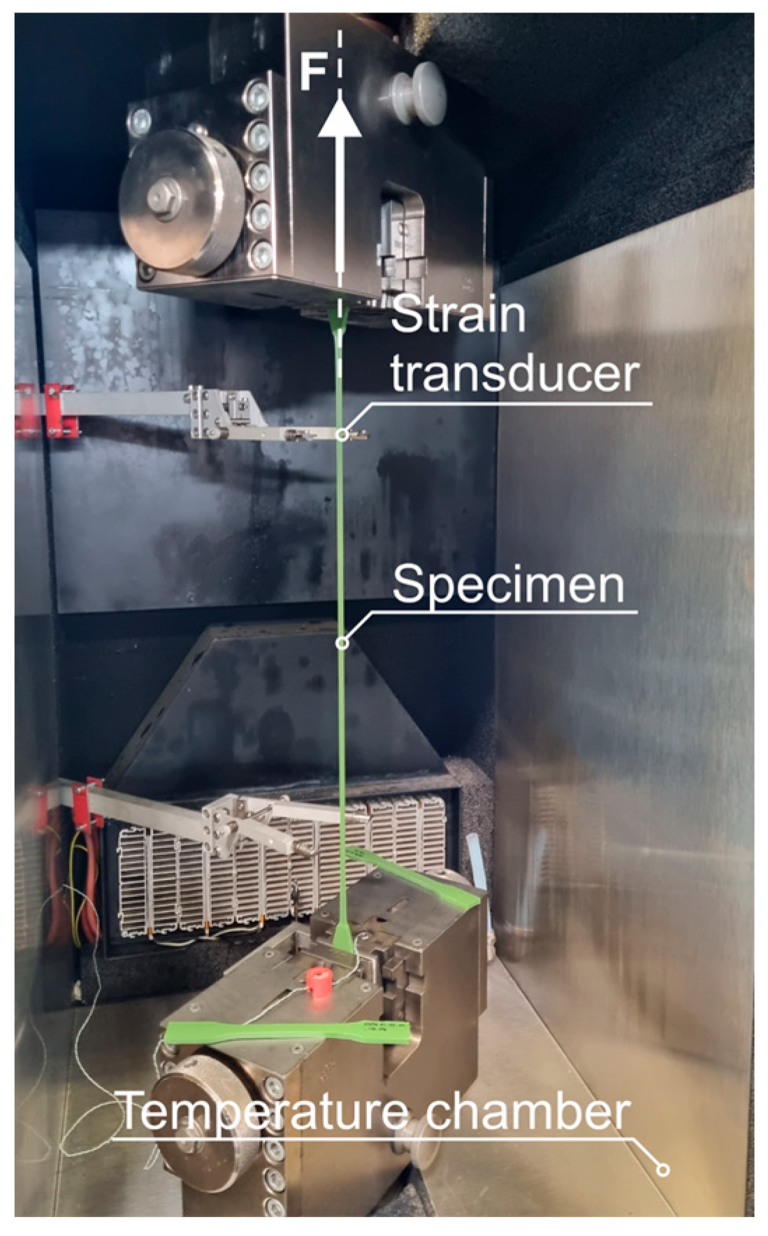
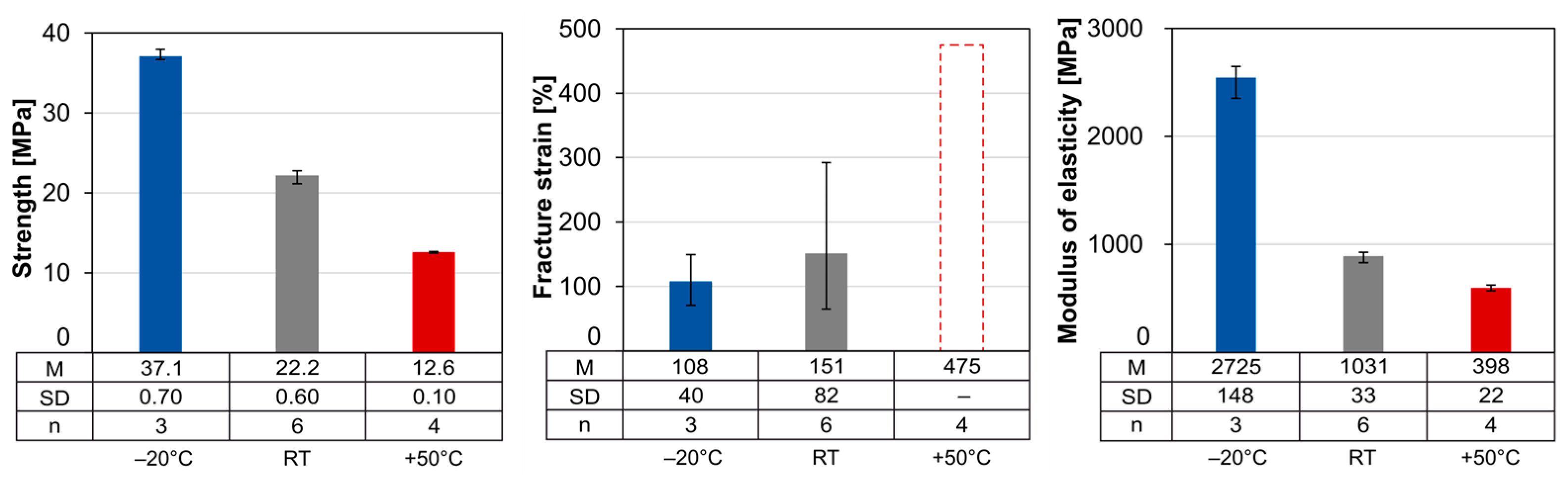
3.4. Temperature Tests
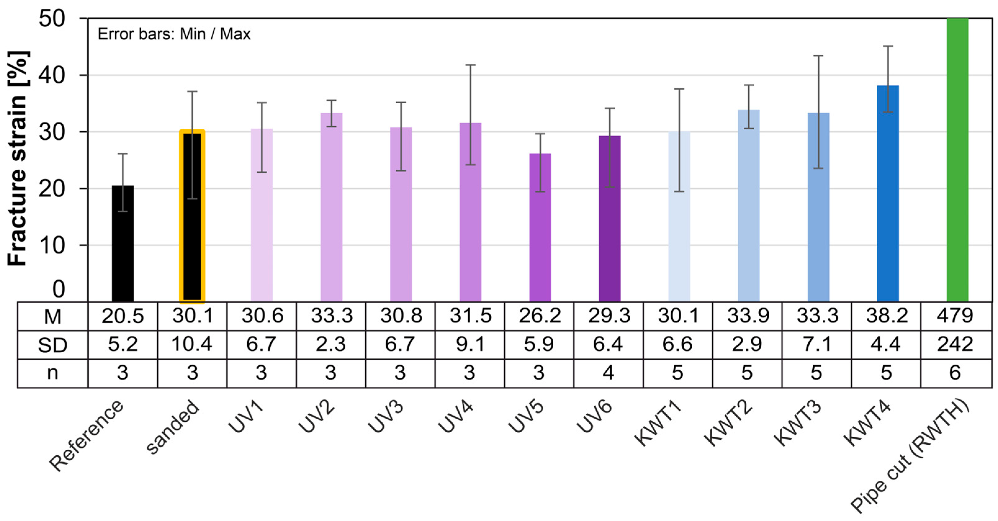
3.5. Accelerated Aging
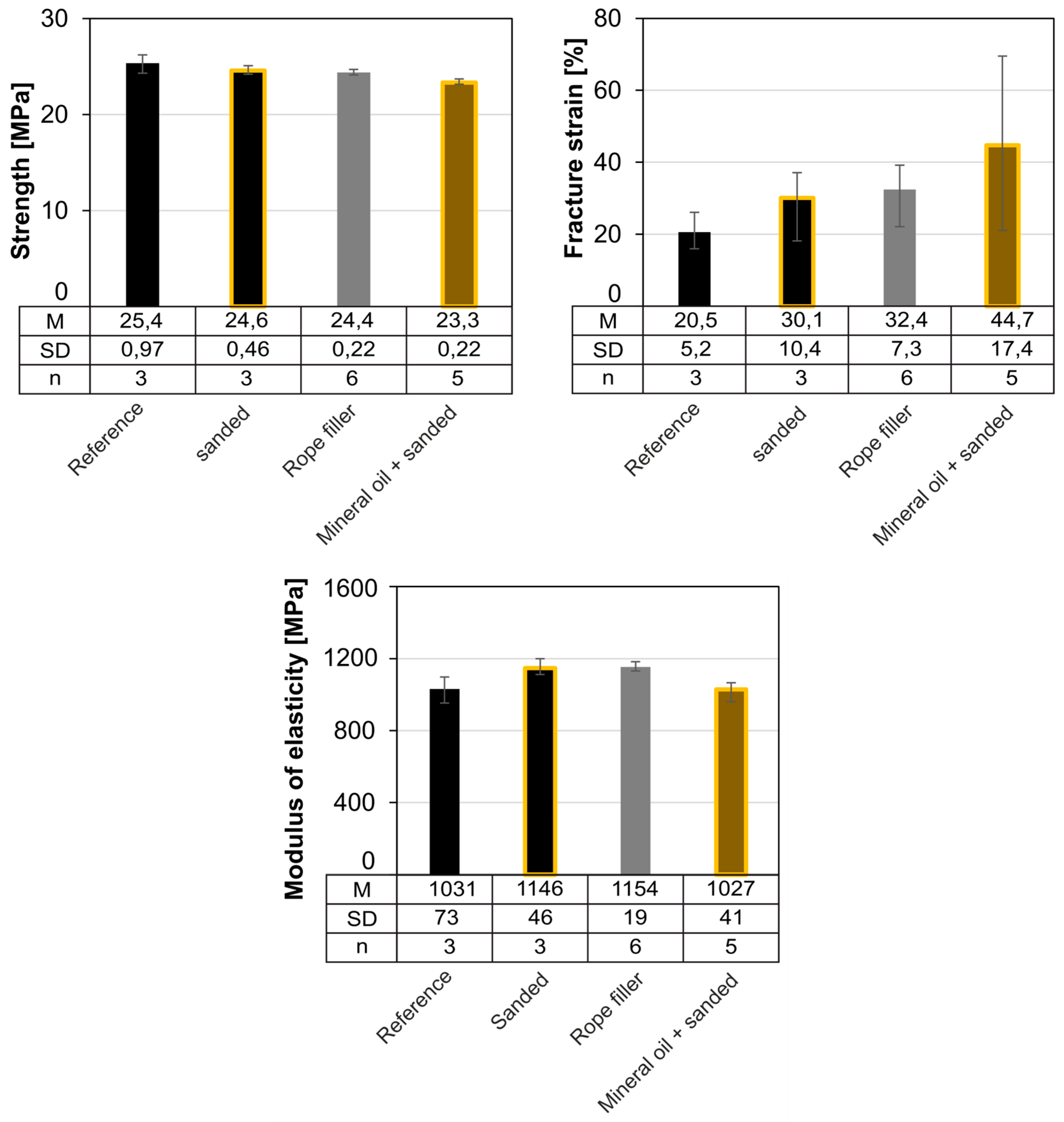
3.6. Compatibility
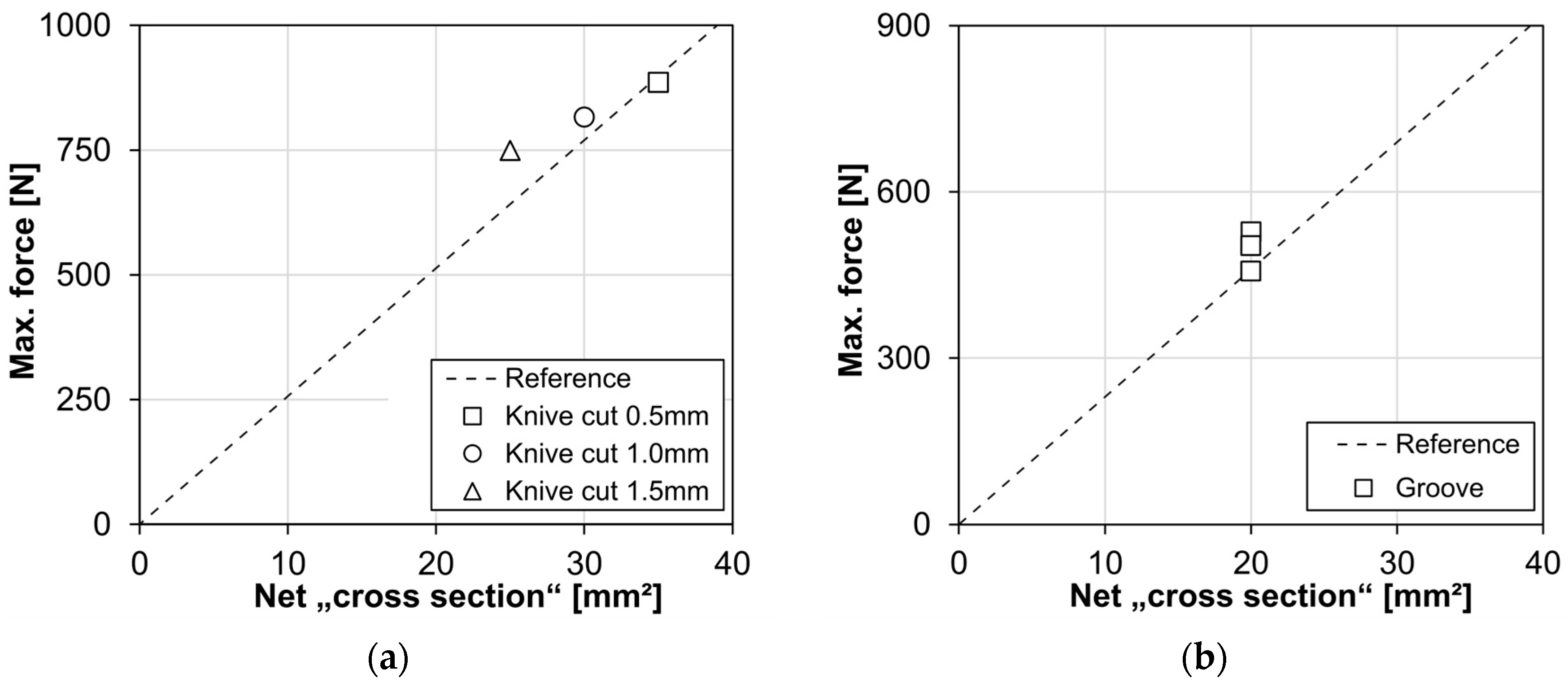
3.7. Knife Cut and Groove
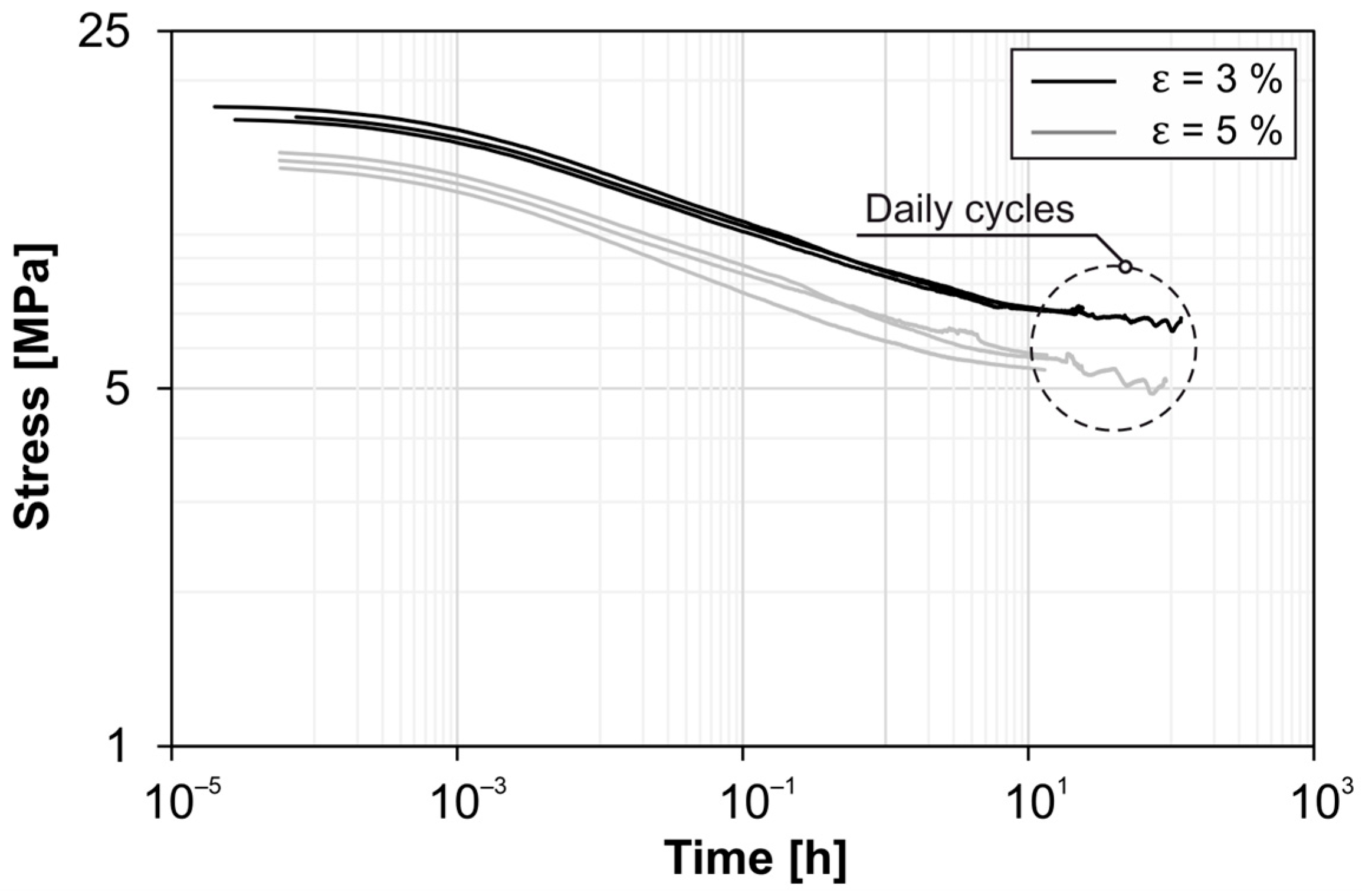
3.8. Relaxation
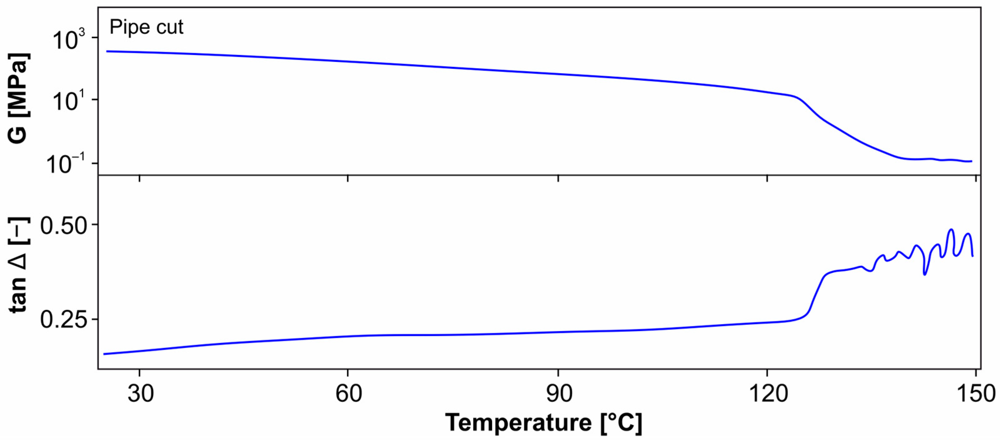
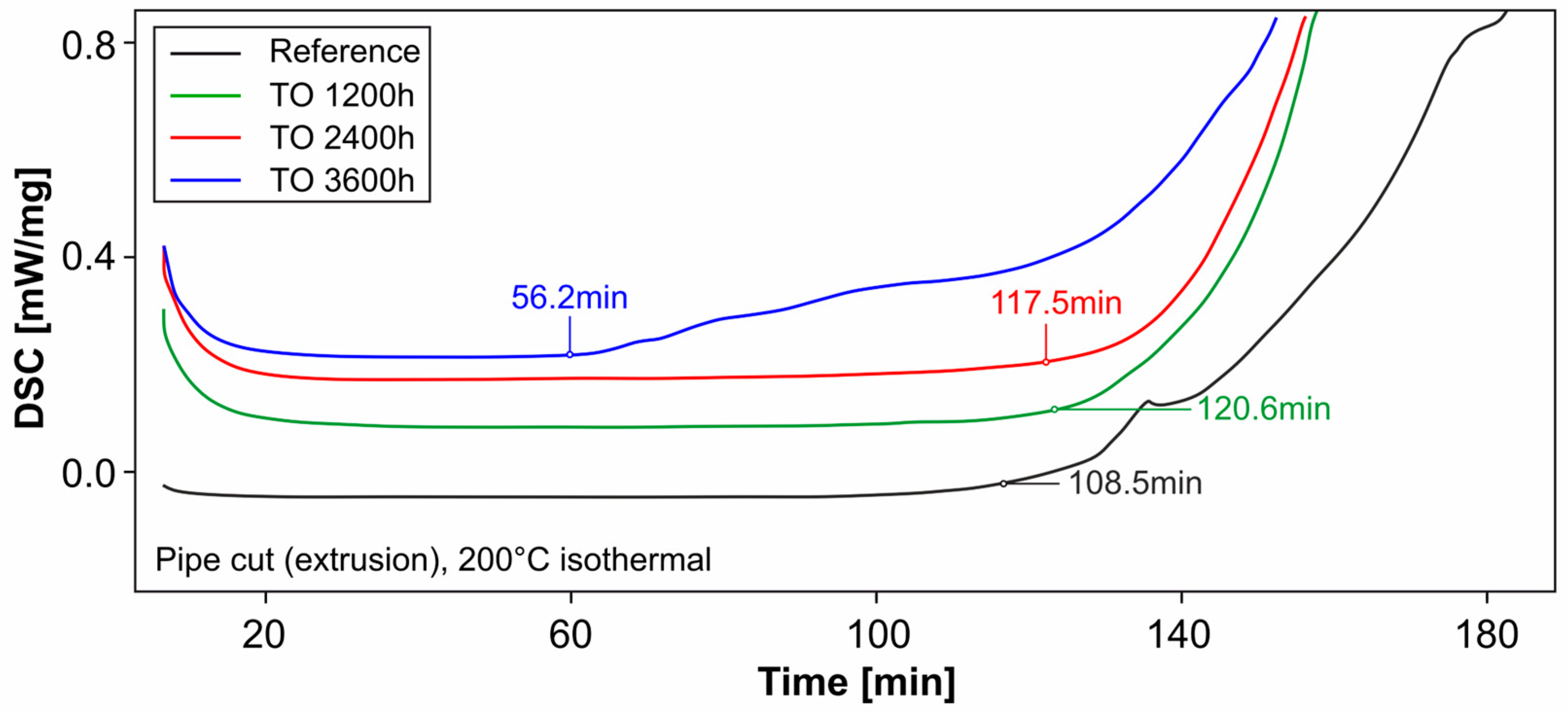
3.9. Differential Scanning Calorimetry and Oxidation Induction
4. Discussion
4.1. Manufacturing Process
4.2. Accelerated Aging Tests
4.3. Influence of Climate Zones and Temperatures
4.4. Exceptional Effects
5. Conclusions and Outlook
Author Contributions
Funding
Institutional Review Board Statement
Informed Consent Statement
Data Availability Statement
Acknowledgments
Conflicts of Interest
References
- Friedrich, H.; Hamme, M. Brückenseile. In Stahlbau Kalender 2021; Kuhlmann, U., Ed.; Ernst & Sohn; John Wiley & Sons Inc., Berlin: Hoboken, NJ, USA, 2021. [Google Scholar] [CrossRef]
- Bundesministerium für Digitales und Verkehr: ZTV-ING Teil 4: Stahlbau, Stahlverbundbau, Abschnitt 5: Korrosionsschutz von Brückenseilen. Available online: https://technical-regulation-information-system.ec.europa.eu/en/notification/26195/text/D/DE (accessed on 19 December 2024).
- Feyrer, K.; Wehking, K.-H. FEYRER—Drahtseile, Bemessung, Betrieb, Sicherheit; Springer Vieweg: Berlin/Heidelberg, Germany, 2017; ISBN 978-3-642-54295-4. [Google Scholar]
- Friedrich, H. Bridge Ropes for Road Bridges—Comparison Between Fully Locked Coil Ropes and Bundles of Parallel Strands. Berichte der Bundesanstalt für Straßenwesen, Heft B 98 Brücken- und Ingenieurbau. 2014. Available online: http://bast.opus.hbz-nrw.de/volltexte/2014/767/pdf/B98b.pdf (accessed on 19 December 2024).
- German Version DIN EN 1993-1-11:2006+AC:2009; Design of Steel Structures—Part 1-11: Design of Structures with Tension Components. Beuth Verlag GmbH: Berlin, Germany, 2010.
- Bundesministerium für Digitales und Verkehr: Technische Lieferbedingungen und Technische Prüfvorschriften für Ingenieurbauten. TL/TP-ING (2022) TL/TP-VVS, Part 4 Section 4 ‘Technical Delivery Conditions and Technical Test Specifications for Fully Locked Bridge Cables’. Available online: https://www.bast.de/DE/Publikationen/Regelwerke/Ingenieurbau/Baudurchfuehrung/TL_TP-Gesamt.pdf (accessed on 19 December 2024).
- fib Bulletin No. 30. Acceptance of Stay Cable Systems Using Prestressing Steals; International Federation for Structural Concrete (fib): Lausanne, Switzerland, 2005; ISBN 978-2-88394-070-3.
- German Version EN ISO 527-2:2012; Plastics—Determination of Tensile Properties—Part 2: Test Conditions for Moulding and Extrusion Plastics. Beuth Verlag GmbH: Berlin, Germany, 2012.
- Millfield Enterprises (Manufacturing) Limited (2023) Wirelock—Technical Data Manual; V10-1123. Available online: https://www.wirelock.com/ (accessed on 19 December 2024).
- German Version EN 13411-4:2021; Terminations for Steel Wire Ropes—Safety—Part 4: Metal and Resin Socketing. German Version EN ISO 13411-4:2022; Beuth Verlag GmbH: Berlin, Germany, 2022.
- Ehrenstein, G. Polymer Werkstoffe, Struktur—Eigenschaften—Anwendungen, 3. Auflage; Carl Hanser Verlag: München, Germany, 2011; ISBN 978-3-446-42283-4. [Google Scholar]
- Ehrenstein, G.; Pongratz, S. Beständigkeit von Kunststoffen. Band 1; Carl Hanser Verlag: München, Germany, 2007; ISBN 978-3-446-21851-2. [Google Scholar]
- Elleuch, R.; Taktak, W. Visocelastic behavior of HDPE Polymer using Tensile and Compressive Loading. J. Mater. Eng. Perform. 2006, 1, 111–116. [Google Scholar] [CrossRef]
- Guo, H.; Rinaldi, R.G.; Tayakout, S.; Broudin, M.; Lame, O. Characterization of the spherulitic deformation in equatorial region and cavitation in HDPE materials submitted to mixed-mode oligo-cyclic tensile loading. Polym. Test. 2021, 99, 107208. [Google Scholar] [CrossRef]
- Chaoui, K.; Ghabeche, W.; Azzouz, S. Study of Crude Oil Interaction with High Density Polyethylene Pipe Surface Material. 24ème Congrès Français de Mécanique. Available online: https://www.researchgate.net/publication/335994735_STUDY_OF_CRUDE_OIL_INTERACTION_WITH_HIGH_DENSITY_POLYETHYLENE_PIPE_SURFACE_MATERIAL (accessed on 19 December 2024).
- DIN EN ISO 179-1; Plastics—Determination of Charpy Impact Properties—Part 1: Non-Instrumented Impact Test. Beuth Verlag GmbH: Berlin, Germany, 2023.
- DIN EN ISO 6259-1; Thermoplastics Pipes—Determination of Tensile Properties—Part 1: General Test Method. Beuth Verlag GmbH: Berlin, Germany, 2015.
- DIN EN ISO 6259-3; Thermoplastics Pipes—Determination of Tensile Properties—Part 3: Polyolefin Pipes. Beuth Verlag GmbH: Berlin, Germany, 2015.
- D1505-18; Standard Test Method for Density of Plastics by the Density-Gradient Technique. ASTM International: West Conshohocken, PA, USA, 2018.
- D1238-23a; Standard Test Method for Melt Flow Rates of Thermoplastics by Extrusion Plastometer. ASTM International: West Conshohocken, PA, USA, 2013.
- Albozahid, M.A.; Diwan, A.A.; Diwan, M.A.; Alansari, L.S. Effect of Weathering on Tensile Properties of Low and High Density Polyethylene. IOP Conf. Ser. Mater. Sci. Eng. 2021, 1094, 012140. Available online: https://iopscience.iop.org/article/10.1088/1757-899X/1094/1/012140 (accessed on 19 December 2024).
- Elkori, R.; Lamarti, A.; Salmi, H.; El Had, K.; Hachim, A.; Yamari, I. Stady of the Effekt of Accelerated Aging by Sea Water on the Mechanical and Chemical Properties of High Density Polyethylene Bottles. Available online: https://www.researchsquare.com/article/rs-1893605/v1 (accessed on 19 December 2024).
- Hsueh, H.-C.; Kim, J.H.; Orski, S.; Fairbrother, A.; Jacobs, D.; Perry, L.; Hunston, D.; White, C.; Sung, L. Micro and macroscopic mechanical behaviors of high-density polyethylene under UV irradiation and temperature. Polym. Degrad. Stab. 2020, 174, 109098. [Google Scholar] [CrossRef]
- Carrasco, F.; Pages, P.; Pascual, S.; Colom, X. Artificial aging of high-density polyethylene by ultraviolet irradiation. Eur. Polym. J. 2001, 37, 1457–1464. [Google Scholar] [CrossRef]
- Zhao, B.; Zhang, S.; Sun, C.; Guo, J.; Yu, Y.X.; Xu, T. Aging behavior and properties evaluation of high-density polyethylene (HDPE) in heating-oxygen environment. IOP Conf. Ser. Mater. Sci. Eng. 2018, 369, 012021. [Google Scholar] [CrossRef]
- Mueller, W.; Jakob, I. Oxidative resistance of high-density polyethylene geomembranes. Polym. Degrad. Stab. 2003, 1, 161–172. [Google Scholar] [CrossRef]
- Ewais, A.; Rowe, R.K. Effect of aging on the stress crack resistance of an HDPE geomembrane. Polym. Degrad. Stab. 2014, 109, 194–208. [Google Scholar] [CrossRef]
- Rowe, R.K.; Ewais, A. Ageing of exposed geomembranes at locations with different climatological conditions. Can. Geotech. J. 2015, 3, 326–343. [Google Scholar] [CrossRef]
- Guermazi, N.; Elleuch, K.; Ayedi, H.F. The effect of time and aging temperature on structural and mechanical properties of pipeline coating. Mater. Des. 2009, 6, 2006–2010. [Google Scholar] [CrossRef]
- Saul, R.; Nützel, O. Neuartige Sanierung der Tragkabel einer Hängebrücke in Norwegen. Stahlbau 2014, 2, 96–100. [Google Scholar] [CrossRef]
- Yu, Y.; Man, M.; Zhao, F.; Lin, S.; Guo, F. Corrosive degradation evaluation of semi-parallel wire cables with high-density polyethylene sheath breaks. Eng. Fail. Anal. 2020, 116, 104714. [Google Scholar] [CrossRef]
- Huang, R.; Yu, J.; Yang, Q.; Chen, J.; Song, Q. Discussion on the Wear Durability of HDPE Outer Sheath for Bridge Cable. Prestress. Technol. 2009, 5, 23–26. [Google Scholar] [CrossRef]
- Liu, S.; Su, H.; Xu, J.; Zhou, Z.; Hao, H.; Wei, L.; Du, J. Experimental study on tensile properties of HDPE sheath for parallel wire suspender after photo-oxidative aging. Constr. Build. Mater. 2024, 416, 135304. [Google Scholar] [CrossRef]
- Mkacher, I.; Brument, Y.; Murin, V.; Sellier, I.; Colin, X. Methodology for evaluating the durability of HDPE outer sheaths of underground electric cables. In Proceedings of the 21st International Conference on Electricity Distribution (CIRED), Frankfurt, Germany, 6–9 June 2011. Paper No 0779. [Google Scholar]
- Lin, B.; Zhang, C. Photo-aging performance of high-density polyethylene sheath in dry environment. In Advances in Civil Engineering: Structural Seismic Resistance, Monitoring and Detection; CRC Press: Boca Raton, FL, USA, 2022. [Google Scholar]
- Dan, D.; Cheng, W.; Sun, L.; Guo, Y. Fatigue durability study of high density polyethylene stay cable sheathing. Constr. Build. Mater. 2016, 111, 474–481. [Google Scholar] [CrossRef]
- Dan, D.; Sun, L.; Guo, Y.; Cheng, W. Study on the Mechanical Properties of Stay Cable HDPE Sheathing Fatigue in Dynamic Bridge Environments. Polymers 2015, 8, 1564–1576. [Google Scholar] [CrossRef]
- Lai, J.; Bakker, A. Analysis of the non-linear creep of high-density polyethylen. Polymer 1994, 1, 93–99. [Google Scholar] [CrossRef]
- Rezakalla, A.I.; Gennadyevech, D.A. Effect of Certain Hydrocarbon Compounds on High-density Polyethylene Water Pipes. Mater. Plast. 2022, 59, 91–99. [Google Scholar] [CrossRef]
- DIN 52348; Testing of Glass and Plastics—Abrasion Test—Sand Trickling Method. Beuth Verlag GmbH: Berlin, Germany, 1985.
- German Version EN ISO 4892-1:2016; Plastics—Methods of Exposure to Laboratory Light Sources—Part 1: General Guidance. Beuth Verlag GmbH: Berlin, Germany, 2016.
- German Version EN ISO 4892-3:2016; Plastics—Methods of Exposure to Laboratory Light Sources—Part 3: Fluorescent UV Lamps. Beuth Verlag GmbH: Berlin, Germany, 2016.
- Grellmann, W.; Seidler, S. Kunststoffprüfung; Hanser: München, Wien, 2015; ISBN 978-3-446-44350-1. [Google Scholar]
- Qiao, Z.; Wu, W.; Wang, Z.; Zhang, L.; Zhou, Y. Space Charge Behavior of Thermally Aged Polyethylene Insulation of Track Cables. Polymers 2022, 11, 2162. [Google Scholar] [CrossRef]
- Mirabella, F.M.; Bafna, A. Determination of the crystallinity of polyethylene/α-olefin copolymers by thermal analysis: Relationship of the heat of fusion of 100% polyethylene crystal and the density. J. Polym. Sci. Part B Polym. Phys. 2002, 15, 1637–1643. [Google Scholar] [CrossRef]
- Lunzhi, L.; Jinghui, G.; Lisheng, Z.; Kai, Z.; Xiaohan, Z. Aging phenomena in non-crosslinked polyolefin blend cable insulation material: In: Electrical treeing and thermal aging. Front. Chem. 2022, 10, 903986. [Google Scholar] [CrossRef]
- Kiersnowska, A.; Fabianowski, W.; Koda, E. The Influence of the Accelerated Aging Conditions on the Properties of Polyolefin Geogrids Used for Landfill Slope Reinforcement. Polymers 2020, 9, 1874. [Google Scholar] [CrossRef]
- Professional Plastics (2024) HDPE and LDPE Resistance Chart by Chemical. Available online: https://www.professionalplastics.com/professionalplastics/HDPE-LDPEChemicalResistanceChart.pdf (accessed on 15 October 2024).
- Rösler, J.; Harders, H.; Bäker, M. Mechanisches Verhalten der Werkstoffe; Springer Vieweg: Wiesbaden, Germany, 2019; ISBN 978-3-8348-1818-8. [Google Scholar]
- Kunststoffe—Dynamische Differenzkalorimetrie (DSC)–Teil1: Allgemeine Grundlagen (ISO11357-1:2023); Deutsche Fassung EN ISO11357-1:2023; Beuth Verlag GmbH: Berlin, Germany, 2023.
- Binnewies, M.; Finze, M.; Jäckel, M.; Schmidt, P.; Willner, H.; Rayner-Canham, G. Allgemeine und Anorganische Chemie; Springer Spektrum: Berlin, Germany, 2016; ISBN 978-3-662-45067-3. [Google Scholar]
- Troughton. Handbook of Plastics Joining: A Practical Guide; William Andrew: Norwich, NY, USA; TWI The Welding Institute: Cambridge, UK, 2008; ISBN 978-0-8155-1581-4. [Google Scholar]


| Test Cycles | Duration | Stages | Conditions |
|---|---|---|---|
| 3 weeks modified aging test PV1200 | 1 h | Heating phase | +50 °C, 80% RH |
| 4 h | Cooling phase | +50 °C, 80% RH | |
| 2 h | Cooling phase | −20 °C, from T < 0 °C non-regulated RH | |
| 4 h | Holding phase | −20 °C, 80% non-regulated RH | |
| 1 h | Heating phase | +23 °C, ab T = 0 °C r. L 30% | |
| 1 week salt spray test PV1210 | 4 h | Salt spray | |
| 4 h | Ambient climate | ||
| 16 h | Condensing water climate, 40 °C | ||
| 3 weeks modified aging test PV1200 | 1 h | Heating phase | +50 °C, 80% RH |
| 4 h | Cooling phase | +50 °C, 80% RH | |
| 2 h | Cooling phase | −20 °C, from T < 0 °C non-regulated RH | |
| 4 h | Holding phase | −20 °C, 80% non-regulated RH | |
| 1 h | Heating phase | +23 °C, ab T = 0 °C r. L 30% | |
| Test Series | Accelerated Aging Procedures | ||
|---|---|---|---|
| sanded | Non-sanded | ||
| Manufacturing: Extrusion | |||
| Reference | – | X | Non-aged reference samples |
| Pipe cut RWTH | – | X | Samples cut from HDPE pipe at the RWTH |
| UV 1200 h | X | X | UV irradiation + condensation, duration: 1200 h/50 d |
| UV 2400 h | X | X | UV irradiation + condensation, duration: 2400 h/100 d |
| UV 3600 h | X | X | UV irradiation + condensation, duration: 3600 h/150 d |
| TO 1200 h | – | X | Oven storage at +60 °C, duration: 1200 h/50 d |
| TO 2400 h | – | X | Oven storage at +60 °C, duration: 2400 h/100 d |
| TO 3600 h | – | X | Oven storage at +60 °C, duration: 3600 h/150 d |
| UV 2400 h + KWT 1200 h | X | – | UV irradiation + condensation, duration: 2400 h/100 d + |
| UV 2400 h + KWT 2400 h | X | – | Aging test PV1200 & PV1210, duration: 1200 h/50 d |
| Cyclically conditioned | X | - | UV irradiation + condensation, duration: 2400 h/100 d + |
| Manufacturing: Injection molding | |||
| Reference | X | X | Non-aged reference samples |
| UV 1 | – | X | UV irradiation + condensation, duration: 7 d |
| UV 2 | – | X | UV irradiation + condensation, duration: 14 d |
| UV 3 | – | X | UV irradiation + condensation, duration: 21 d |
| UV 4 | – | X | UV irradiation + condensation, duration: 28 d |
| UV 5 | – | X | UV irradiation + condensation, duration: 35 d |
| UV 6 | – | X | UV irradiation + condensation, duration: 42 d |
| KWT 1 | – | X | 21 d KWT (−20/+50 °C 80% RH) |
| KWT 2 | – | X | 21 d KWT (−20/+50 °C 80% RH) + 2 d NK + 5 d PV1210 (salt spray test) |
| KWT 3 | – | X | 21 d KWT (−20/+50 °C 80% RH) + 2 d NK + 5 d PV1210 (salt spray test) + 2 d NK + 21 d KWT (−20/+50 °C 80% RH) |
| KWT 4 | – | X | 2 cycles: 21 d KWT (−20/+50 °C 80% RH) + 2 d NK + 5 d PV1210 (salt spray test) + 2 d NK + 21 d KWT (−20/+50 °C 80% RH) |
| Rope filler | – | – | Storage in rope filler, duration: 1200 h/50 d, RT |
| Mineral oil | X | – | Storage in mineral oil, duration: 1200 h/50 d, RT |
| Tensile Strength [MPa] | Fracture Strain [%] | Modulus of Elasticity [MPa] | ||
|---|---|---|---|---|
| Injection molded | M | 25.4 | 20.5 | 1031 |
| SD | 0.97 | 5.2 | 73 | |
| Pipe cut manufacturer | M | 22.2 | 151 | 1031 |
| SD | 0.61 | 82 | 33 | |
| Pipe cut | M | 23.7 | 479 | 1306 |
| SD | 0.28 | 242 | 159 |
| t = 0 h | t = 12 h | t = 24 h | t = 120 h | ||||||||
|---|---|---|---|---|---|---|---|---|---|---|---|
| ε | σ0 | E | σ | σ/σ0 | E | σ | σ/σ0 | E | σ | σ/σ0 | E |
| [%] | [MPa] | [MPa] | [MPa] | [%] | [MPa] | [MPa] | [%] | [MPa] | [MPa] | [%] | [MPa] |
| 3.0 | 13.97 | 466 | 5.68 | 40.6 | 189 | 5.41 | 37.4 | 180 | 5.19 | 35.9 | 173 |
| 5.0 | 17.17 | 343 | 7.14 | 41.6 | 143 | 7.10 | 41.4 | 142 | 7.05 | 41.1 | 141 |
Disclaimer/Publisher’s Note: The statements, opinions and data contained in all publications are solely those of the individual author(s) and contributor(s) and not of MDPI and/or the editor(s). MDPI and/or the editor(s) disclaim responsibility for any injury to people or property resulting from any ideas, methods, instructions or products referred to in the content. |
© 2024 by the authors. Licensee MDPI, Basel, Switzerland. This article is an open access article distributed under the terms and conditions of the Creative Commons Attribution (CC BY) license (https://creativecommons.org/licenses/by/4.0/).
Share and Cite
Schaaf, B.; Abeln, B.; Feldmann, M.; Stammen, E.; Dilger, K. Full-Locked Coil Ropes with HDPE Sheath: Studies of Mechanical Behavior of HDPE Under Accelerated Aging. Materials 2025, 18, 106. https://doi.org/10.3390/ma18010106
Schaaf B, Abeln B, Feldmann M, Stammen E, Dilger K. Full-Locked Coil Ropes with HDPE Sheath: Studies of Mechanical Behavior of HDPE Under Accelerated Aging. Materials. 2025; 18(1):106. https://doi.org/10.3390/ma18010106
Chicago/Turabian StyleSchaaf, Benjamin, Björn Abeln, Markus Feldmann, Elisabeth Stammen, and Klaus Dilger. 2025. "Full-Locked Coil Ropes with HDPE Sheath: Studies of Mechanical Behavior of HDPE Under Accelerated Aging" Materials 18, no. 1: 106. https://doi.org/10.3390/ma18010106
APA StyleSchaaf, B., Abeln, B., Feldmann, M., Stammen, E., & Dilger, K. (2025). Full-Locked Coil Ropes with HDPE Sheath: Studies of Mechanical Behavior of HDPE Under Accelerated Aging. Materials, 18(1), 106. https://doi.org/10.3390/ma18010106