
Optimizing Alkyl Side Chains in Difluorobenzene–Rhodanine Small-Molecule Acceptors for Organic Solar Cells


Abstract
1. Introduction
2. Experimental Section
2.1. Materials
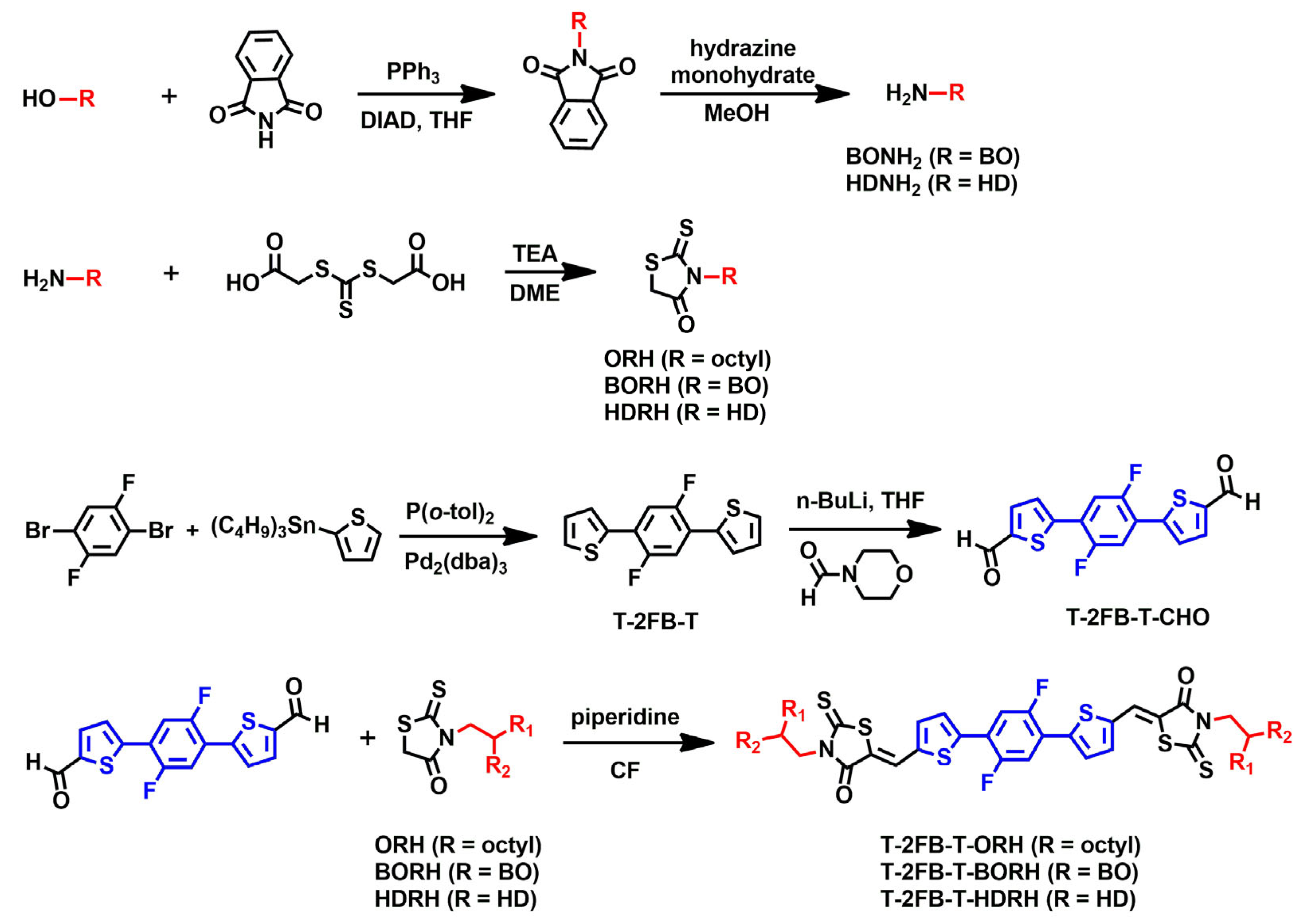
2.2. Synthesis
2.2.1. N-(2-Hexyldecyl)phthalimide (HDphth) [33]
2.2.2. 2-Hexyldecylamine (HDNH2) [34]
2.2.3. 3-(2-Hexyldecyl)rhodanine (HDRH) [23,36]
2.2.4. 2,2′-(2,5-Difluoro-1,4-phenylene)dithiophene (T-2FB-T) [36]
2.2.5. 5,5′-(2,5-Difluoro-1,4-phenylene)bis(thiophene-2-carbaldehyde) (T-2FB-T-CHO) [37]
2.2.6. Synthesis of T-2FB-T-ORH [32,38]
2.2.7. Synthesis of T-2FB-T-BORH
2.2.8. Synthesis of T-2FB-T-HDRH
2.3. Measurement
2.4. Fabrication of OSC Devices
3. Results and Discussion
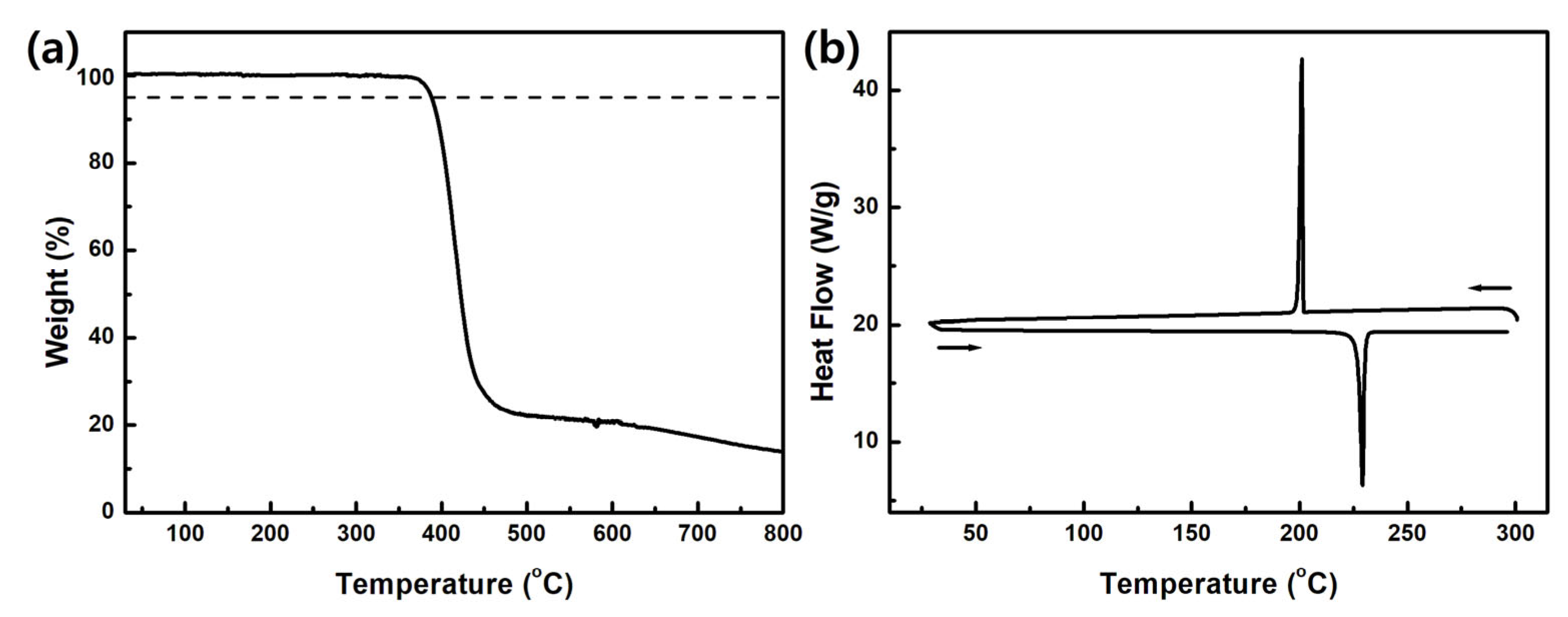
3.1. Synthesis and Thermal Properties
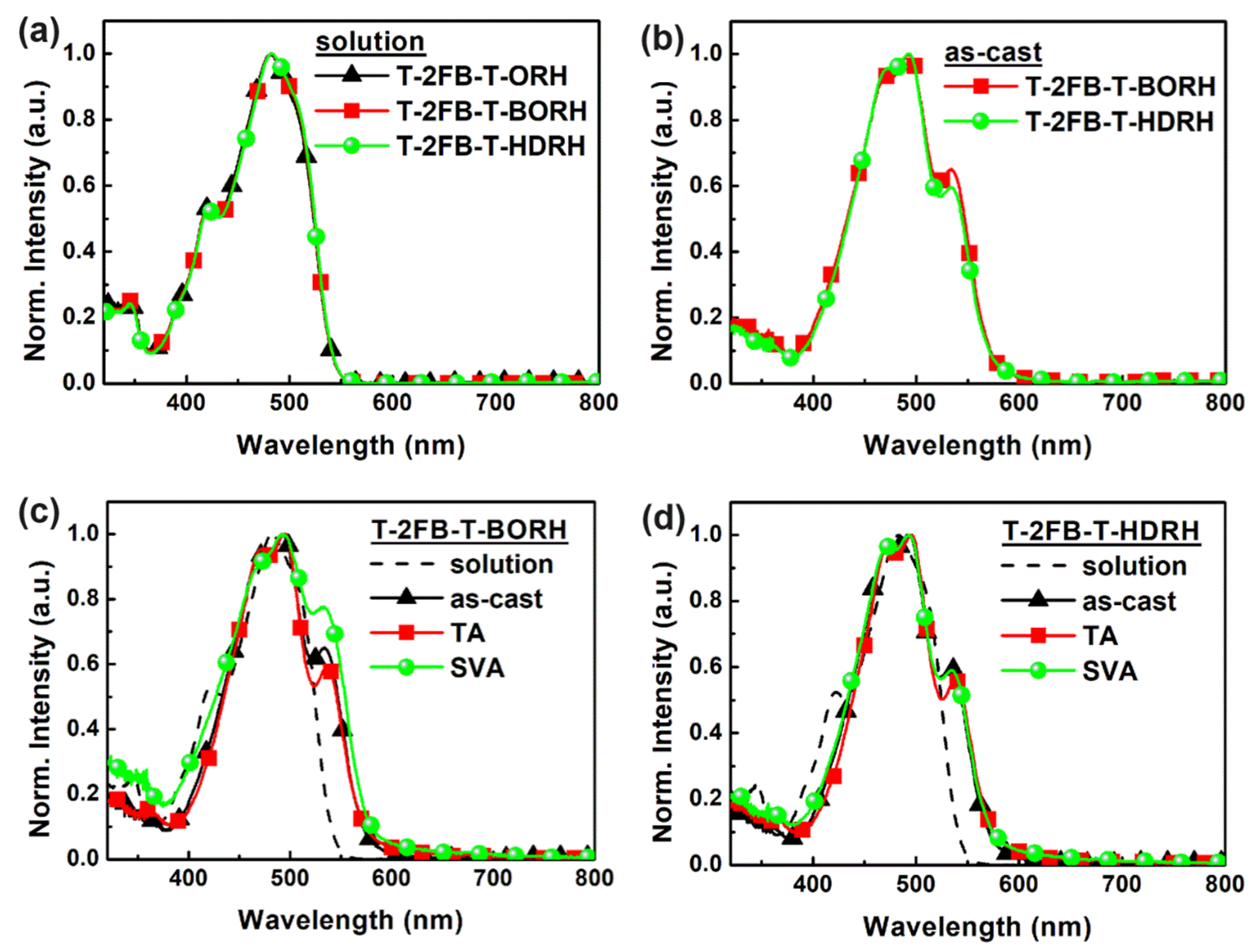
3.2. Optical and Electrochemical Properties
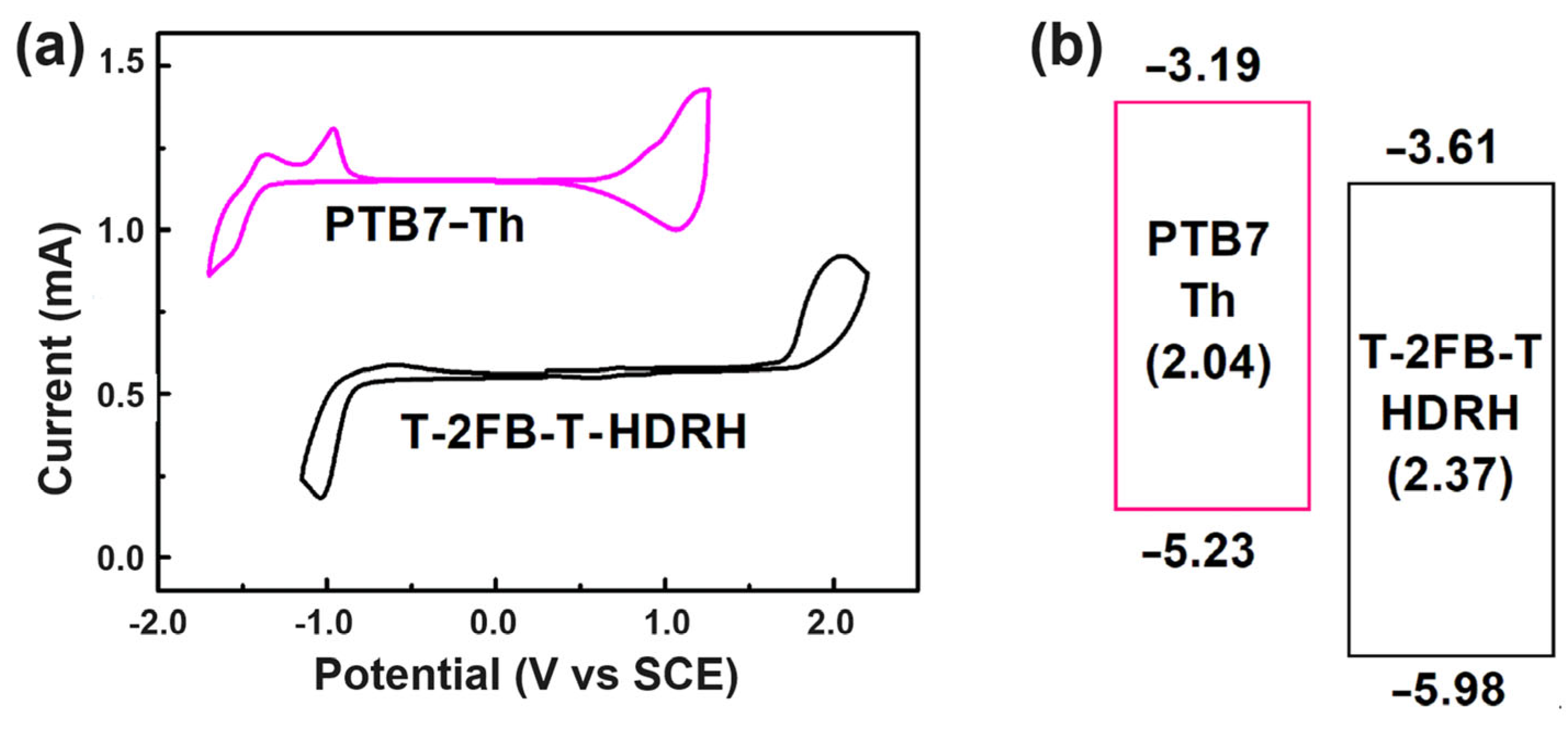
3.3. Electrochemical Properties
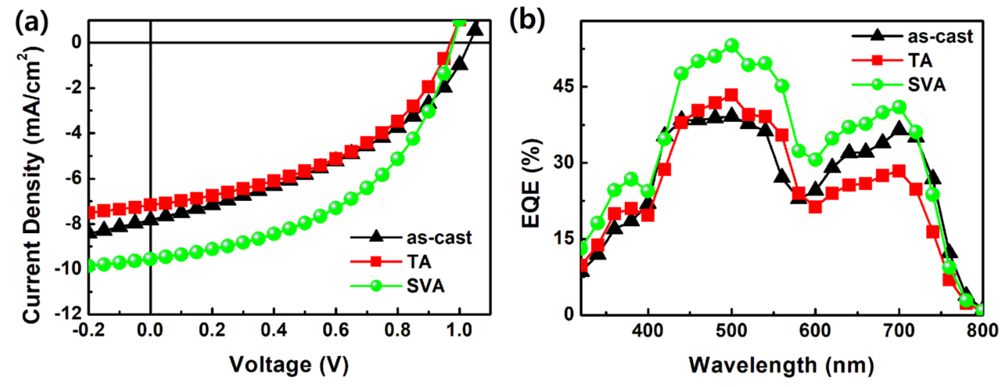
3.4. Device Performances
4. Conclusions
Supplementary Materials
Author Contributions
Funding
Institutional Review Board Statement
Informed Consent Statement
Data Availability Statement
Conflicts of Interest
References
- Xu, Y.; Wang, Q.; Zou, W.; Zhang, X.; Sun, Y.; Kan, Y.; Cai, P.; Gao, K. Recent Progress in All-Solution-Processed Organic Solar Cells. Chin. J. Chem. 2024, 42, 190–198. [Google Scholar] [CrossRef]
- Li, Y.; Huang, W.; Zhao, D.; Wang, L.; Jiao, Z.; Huang, Q.; Wang, P.; Sun, M.; Yuan, G. Recent Progress in Organic Solar Cells: A Review on Materials from Acceptor to Donor. Molecules 2022, 27, 1800. [Google Scholar] [CrossRef] [PubMed]
- Kim, Y.; Lim, E. Development of Polymer Acceptors for Organic Photovoltaic Cells. Polymers 2014, 6, 382–407. [Google Scholar] [CrossRef]
- Ganesamoorthy, R.; Sathiyan, G.; Sakthivel, P. Review: Fullerene based acceptors for efficient bulk heterojunction organic solar cell applications. Sol. Energy Mater. Sol. Cells 2017, 161, 102–148. [Google Scholar] [CrossRef]
- Chung, D.; Balamurugan, C.; Park, B.; Lee, H.; Cho, I.; Yoon, C.; Park, S.; Jo, Y.-R.; Jeon, J.; Hong, S.; et al. Fast-Growth Polymer: Fullerene Bulk-Heterojunction Thin Films for Efficient Organic Photovoltaics. Nanomaterials 2024, 14, 502. [Google Scholar] [CrossRef] [PubMed]
- Zhang, Y.; Lang, Y.; Li, G. Recent advances of non-fullerene organic solar cells: From materials and morphology to devices and applications. EcoMat 2023, 5, e12281. [Google Scholar] [CrossRef]
- Luo, D.; Jang, W.; Babu, D.D.; Kim, M.S.; Wang, D.H.; Kyaw, A.K.K. Recent progress in organic solar cells based on non-fullerene acceptors: Materials to devices. J. Mater. Chem. A 2022, 10, 3255–3295. [Google Scholar] [CrossRef]
- Liu, Q.; Jiang, Y.; Jin, K.; Qin, J.; Xu, J.; Li, W.; Xiong, J.; Liu, J.; Xiao, Z.; Sun, K.; et al. 18% Efficiency organic solar cells. Sci. Bull. 2020, 65, 272–275. [Google Scholar] [CrossRef] [PubMed]
- Zheng, Z.; Wang, J.; Bi, P.; Ren, J.; Wang, Y.; Yang, Y.; Liu, X.; Zhang, S.; Hou, J. Tandem Organic Solar Cell with 20.2% Efficiency. Joule 2022, 6, 171–184. [Google Scholar] [CrossRef]
- Liu, G.; Xia, R.; Huang, Q.; Zhang, K.; Hu, Z.; Jia, T.; Liu, X.; Yip, H.-L.; Huang, F. Tandem Organic Solar Cells with 18.7% Efficiency Enabled by Suppressing the Charge Recombination in Front Sub-Cell. Adv. Funct. Mater. 2021, 31, 2103283. [Google Scholar] [CrossRef]
- Du, W.-S.; Wang, G.; Li, Y.-F.; Yu, Y. Development of fullerene acceptors and the application of non-fullerene acceptors in organic solar cells. Front. Phys. 2024, 12, 1378909. [Google Scholar] [CrossRef]
- Kim, Y.; Song, C.E.; Moon, S.-J.; Lim, E. Rhodanine dye-based small molecule acceptors for organic photovoltaic cells. Chem. Commun. 2014, 50, 8235–8238. [Google Scholar] [CrossRef] [PubMed]
- Suman; Bagui, A.; Datt, R.; Gupta, V.; Singh, S.P. A simple fluorene core-based non-fullerene acceptor for high performance organic solar cells. Chem. Commun. 2017, 53, 12790–12793. [Google Scholar] [CrossRef] [PubMed]
- Chen, Y.; Liu, T.; Ma, L.-K.; Xue, W.; Ma, R.; Zhang, J.; Ma, C.; Kim, H.K.; Yu, H.; Bai, F.; et al. Alkoxy substitution on IDT-Series and Y-Series non-fullerene acceptors yielding highly efficient organic solar cells. J. Mater. Chem. A 2021, 9, 7481–7490. [Google Scholar] [CrossRef]
- Liu, Y.; Li, M.; Yang, J.; Xue, W.; Feng, S.; Song, J.; Tang, Z.; Ma, W.; Bo, Z. High-Efficiency As-Cast Organic Solar Cells Based on Acceptors with Steric Hindrance Induced Planar Terminal Group. Adv. Energy Mater. 2019, 9, 1901280. [Google Scholar] [CrossRef]
- Khlaifia, D.; Ettaghzouti, T.; Chemek, M.; Alimi, K. Indacenodithiophene (IDT) and indacenodithienothiophene (IDTT)-based acceptors for non-fullerene organic solar cells. Synth. Met. 2021, 274, 116736. [Google Scholar] [CrossRef]
- Zhang, Z.; Guang, S.; Yu, J.; Wang, H.; Cao, J.; Du, F.; Wang, X.; Tang, W. Over 15.5% efficiency organic solar cells with triple sidechain engineered ITIC. Sci. Bull. 2020, 65, 1533–1536. [Google Scholar] [CrossRef] [PubMed]
- Cevher, D.; Cevher, S.C.; Cirpan, A. Recently developed benzodithiophene based organic solar cells: A review on materials and strategies. Mater. Today Commun. 2023, 37, 107524. [Google Scholar] [CrossRef]
- Luo, Z.; Sun, R.; Zhong, C.; Liu, T.; Zhang, G.; Zou, Y.; Jiao, X.; Min, J.; Yang, C. Altering alkyl-chains branching positions for boosting the performance of small-molecule acceptors for highly efficient nonfullerene organic solar cells. Sci. China Chem. 2020, 63, 361–369. [Google Scholar] [CrossRef]
- Chen, S.; Feng, L.; Jia, T.; Jing, J.; Hu, Z.; Zhang, K.; Huang, F. High-performance polymer solar cells with efficiency over 18% enabled by asymmetric side chain engineering of non-fullerene acceptors. Sci. China Chem. 2021, 64, 1192–1199. [Google Scholar] [CrossRef]
- Luo, Z.; Sun, C.; Chen, S.; Zhang, Z.-G.; Wu, K.; Qiu, B.; Yang, C.; Li, Y.; Yang, C. Side-Chain Impact on Molecular Orientation of Organic Semiconductor Acceptors: High Performance Nonfullerene Polymer Solar Cells with Thick Active Layer over 400 nm. Adv. Energy Mater. 2018, 8, 1800856. [Google Scholar] [CrossRef]
- Luo, Z.; Yan, H.; Yang, C. End-Group Engineering of Nonfullerene Acceptors for High-Efficiency Organic Solar Cells. Accounts Mater. Res. 2023, 4, 968–981. [Google Scholar] [CrossRef]
- Lee, T.; Eom, Y.; Song, C.E.; Jung, I.H.; Kim, D.; Lee, S.K.; Shin, W.S.; Lim, E. Simple Bithiophene–Rhodanine-Based Small Molecule Acceptor for Use in Additive-Free Nonfullerene OPVs with Low Energy Loss of 0.51 eV. Adv. Energy Mater. 2019, 9, 1804021. [Google Scholar] [CrossRef]
- Choe, J.-c.; Lee, T.H.; Lim, E. Non-Fullerene Small Molecule Acceptors Containing Barbituric Acid End Groups for Use in High-performance OPVs. Bull. Korean Chem. Soc. 2019, 40, 20–23. [Google Scholar] [CrossRef]
- Feng, H.; Qiu, N.; Wang, X.; Wang, Y.; Kan, B.; Wan, X.; Zhang, M.; Xia, A.; Li, C.; Liu, F.; et al. An A-D-A Type Small-Molecule Electron Acceptor with End-Extended Conjugation for High Performance Organic Solar Cells. Chem. Mater. 2017, 29, 7908–7917. [Google Scholar] [CrossRef]
- Deng, M.; Xu, X.; Duan, Y.; Yu, L.; Li, R.; Peng, Q. Y-Type Non-Fullerene Acceptors with Outer Branched Side Chains and Inner Cyclohexane Side Chains for 19.36% Efficiency Polymer Solar Cells. Adv. Mater. 2023, 35, 2210760. [Google Scholar] [CrossRef] [PubMed]
- Wu, Z.; Zhao, Q.; Luo, X.; Ma, H.; Zheng, W.; Yu, J.; Zhang, Z.; Zhang, K.; Qu, K.; Yang, R.; et al. Low-Cost Fabrication of High-Performance Fluorinated Polythiophene-Based Vis–NIR Electrochromic Devices toward Deformable Display and Camouflage. Chem. Mater. 2022, 34, 9923–9933. [Google Scholar] [CrossRef]
- Zhou, X.; Pang, S.; Wu, B.; Zhou, J.; Tang, H.; Lin, K.; Xie, Z.; Duan, C.; Huang, F.; Cao, Y. Noncovalent Interactions Induced by Fluorination of the Central Core Improve the Photovoltaic Performance of A-D-A′-D-A-Type Nonfused Ring Acceptors. ACS Appl. Energy Mater. 2022, 5, 7710–7718. [Google Scholar] [CrossRef]
- Lee, T.; Song, C.E.; Lee, S.K.; Shin, W.S.; Lim, E. Alkyl-Side-Chain Engineering of Nonfused Nonfullerene Acceptors with Simultaneously Improved Material Solubility and Device Performance for Organic Solar Cells. ACS Omega 2021, 6, 4562–4573. [Google Scholar] [CrossRef]
- Ye, L.; Weng, K.; Xu, J.; Du, X.; Chandrabose, S.; Chen, K.; Zhou, J.; Han, G.; Tan, S.; Xie, Z.; et al. Unraveling the influence of non-fullerene acceptor molecular packing on photovoltaic performance of organic solar cells. Nat. Commun. 2020, 11, 6005. [Google Scholar] [CrossRef]
- Qin, H.; Xia, S.; Sun, D.; Wu, Z.; Wang, Y.; Ran, Y.; Lu, G.; Woo, H.Y.; Zhao, B.; Gao, C.; et al. Optimal bulk morphology via side-chain engineering on non-fullerene acceptor for efficient organic solar cells. J. Mater. Chem. C 2022, 10, 16397–16406. [Google Scholar] [CrossRef]
- Lee, T.; Oh, S.; Rasool, S.; Song, C.E.; Kim, D.; Lee, S.K.; Shin, W.S.; Lim, E. Non-halogenated solvent-processed ternary-blend solar cells via alkyl-side-chain engineering of a non-fullerene acceptor and its application in large-area devices. J. Mater. Chem. A 2020, 8, 10318–10330. [Google Scholar] [CrossRef]
- Gassner, A.L.; Duhot, C.; Bünzli, J.C.G.; Chauvin, A.S. Remarkable Tuning of the Photophysical Properties of Bifunctional Lanthanide tris(Dipicolinates) and its Consequence on the Design of Bioprobes. Inorg. Chem. 2008, 47, 7802–7812. [Google Scholar] [CrossRef] [PubMed]
- Do, T.T.; Pham, H.D.; Manzhos, S.; Bell, J.M.; Sonar, P. Molecular Engineering Strategy for High Efficiency Fullerene-Free Organic Solar Cells Using Conjugated 1,8-Naphthalimide and Fluorenone Building Blocks. ACS Appl. Mater. Interfaces 2017, 9, 16967–16976. [Google Scholar] [CrossRef] [PubMed]
- Cha, P.-H.; Cho, Y.-H.; Lee, S.-K.; Lee, J.; Jeong, W.-J.; Moon, B.-S.; Yun, J.-H.; Yang, J.S.; Choi, S.; Yoon, J.; et al. Small-molecule binding of the axin RGS domain promotes β-catenin and Ras degradation. Nat. Chem. Biol. 2016, 12, 593. [Google Scholar] [CrossRef] [PubMed]
- Lee, W.H.; Lee, S.K.; Shin, W.S.; Moon, S.J.; Park, M.J.; Kang, I.N. Synthesis of new acenaphtho[1,2-c]thiophene-based low bandgap polymers for organic photovoltaics. Sol. Energy Mater. Sol. Cells 2014, 122, 190–196. [Google Scholar] [CrossRef]
- Chen, L.; Huang, L.; Yang, D.; Ma, S.; Zhou, X.; Zhang, J.; Tu, G.; Li, C. A non-fullerene acceptor with all "A" units realizing high open-circuit voltage solution-processed organic photovoltaics. J. Mater. Chem. A 2014, 2, 2657–2662. [Google Scholar] [CrossRef]
- Zhou, J.; Zuo, Y.; Wan, X.; Long, G.; Zhang, Q.; Ni, W.; Liu, Y.; Li, Z.; He, G.; Li, C.; et al. Solution-Processed and High-Performance Organic Solar Cells Using Small Molecules with a Benzodithiophene Unit. J. Am. Chem. Soc. 2013, 135, 8484–8487. [Google Scholar] [CrossRef]
- Manor, A.; Katz, E.A. Open-circuit voltage of organic photovoltaics: Implications of the generalized Einstein relation for disordered semiconductors. Sol. Energy Mater. Sol. Cells 2012, 97, 132–138. [Google Scholar] [CrossRef]
- Noori, K.; Konios, D.; Stylianakis, M.M.; Kymakis, E.; Giustino, F. Energy-level alignment and open-circuit voltage at graphene/polymer interfaces: Theory and experiment. 2D Mater. 2016, 3, 015003. [Google Scholar] [CrossRef]
- Galagan, Y.; Mescheloff, A.; Veenstra, S.C.; Andriesen, R.; Katz, E.A. Reversible degradation in ITO-containing organic photovoltaics under concentrated sunlight. Phys. Chem. Chem. Phys. 2015, 17, 3891–3897. [Google Scholar] [CrossRef] [PubMed]
- Stylianakis, M.M.; Konios, D.; Petridis, K.; Kymakis, E. Solution-Processed Graphene-Based Transparent Conductive Electrodes as Ideal ITO Alternatives for Organic Solar Cells. In Graphene Materials—Advanced Applications; Kyzas, G.Z., Mitropoulos, A.C., Eds.; IntechOpen: London, UK, 2017; Volume 3, pp. 154–196. [Google Scholar]


| Acceptor | λmax (λshoulder) [nm] a | λonset b [nm] | Eg,opt c [eV] | |||
|---|---|---|---|---|---|---|
| Solution | As-Cast | SVA | TA | |||
| T-2FB-T-ORH | 481 | - | - | - | - | - |
| T-2FB-T-BORH | 482 | 493 (534) | 494 (533) | 496 (536) | 577 | 2.15 |
| T-2FB-T-HDRH | 483 | 494 (533) | 494 (534) | 496 (536) | 572 | 2.17 |
| Acceptor | Eonset,ox [V] | Eonset,red [V] | EHOMO,CV [eV] | ELUMO,CV [eV] | Eg,CV [eV] |
|---|---|---|---|---|---|
| T-2FB-T-HDRH | 1.29 | –1.08 | –5.98 | –3.61 | 2.37 |
| VOC [V] | JSC [mA/cm2] | FF [%] | PCE [%] | |
|---|---|---|---|---|
| As-cast | 1.03 | 7.84 | 40 | 3.20 |
| SVA | 0.98 | 9.55 | 48 | 4.49 |
| TA | 0.97 | 7.17 | 45 | 3.12 |
Disclaimer/Publisher’s Note: The statements, opinions and data contained in all publications are solely those of the individual author(s) and contributor(s) and not of MDPI and/or the editor(s). MDPI and/or the editor(s) disclaim responsibility for any injury to people or property resulting from any ideas, methods, instructions or products referred to in the content. |
© 2024 by the authors. Licensee MDPI, Basel, Switzerland. This article is an open access article distributed under the terms and conditions of the Creative Commons Attribution (CC BY) license (https://creativecommons.org/licenses/by/4.0/).
Share and Cite
Choi, J.; Song, C.E.; Lim, E. Optimizing Alkyl Side Chains in Difluorobenzene–Rhodanine Small-Molecule Acceptors for Organic Solar Cells. Materials 2024, 17, 1875. https://doi.org/10.3390/ma17081875
Choi J, Song CE, Lim E. Optimizing Alkyl Side Chains in Difluorobenzene–Rhodanine Small-Molecule Acceptors for Organic Solar Cells. Materials. 2024; 17(8):1875. https://doi.org/10.3390/ma17081875
Chicago/Turabian StyleChoi, Jongchan, Chang Eun Song, and Eunhee Lim. 2024. "Optimizing Alkyl Side Chains in Difluorobenzene–Rhodanine Small-Molecule Acceptors for Organic Solar Cells" Materials 17, no. 8: 1875. https://doi.org/10.3390/ma17081875
APA StyleChoi, J., Song, C. E., & Lim, E. (2024). Optimizing Alkyl Side Chains in Difluorobenzene–Rhodanine Small-Molecule Acceptors for Organic Solar Cells. Materials, 17(8), 1875. https://doi.org/10.3390/ma17081875