Article

Enhanced Catalytic Hydrogenation of Olefins in Sulfur-Rich Naphtha Using Molybdenum Carbide Supported on γ-Al2O3 Spheres under Steam Conditions: Simulating the Hot Separator Stream Process

by
Hadj Abbas Abbas
1,
Zahra Asgar Pour
2,*,
Mohammed S. Alnafisah
3,
Pablo Gonzalez Cortes
4,5,
Mustapha El Hariri El Nokab
6,
Ahmed Elshewy
7 and
Khaled O. Sebakhy
8,9,*
1
Laboratoire de géologie du Sahara, Université Kasdi Merbah Ouargla, Ouargla 30000, Algeria
2
Research and Development Department, Kisuma Chemicals, Billitonweg 7, 9641 KZ Veendam, The Netherlands
3
King Abdulaziz City for Science and Technology (KACST), Riyadh 12354, Saudi Arabia
4
Engineering and Technology Institute Groningen (ENTEG), University of Groningen, Nijenborgh 4, 9747 AG Groningen, The Netherlands
5
Laboratorio de Nanocelulosa y Biomateriales, Departamento de Ingeniería Química, Biotecnología y Materiales, Facultad de Ciencias Físicas y Matemáticas, Universidad de Chile, Avenida Beauchef 851, Santiago 8330111, Chile
6
Department of Chemistry, Michigan State University, East Lansing, MI 48824, USA
7
Department of Pharmaceutical Organic Chemistry, Faculty of Pharmacy, Cairo University, Cairo 11562, Egypt
8
Laboratory for Chemical Technology (LCT), Department of Materials, Textiles and Chemical Engineering, Ghent University, Technologiepark 125, 9052 Ghent, Belgium
9
Department of Chemical and Petroleum Engineering, University of Calgary, Calgary, AB T2N 1N4, Canada
*
Authors to whom correspondence should be addressed.
Materials 2024, 17(10), 2278; https://doi.org/10.3390/ma17102278
Submission received: 21 March 2024 / Revised: 26 April 2024 / Accepted: 7 May 2024 / Published: 11 May 2024
(This article belongs to the Special Issue Design and Applications of Functional Materials, Volume II)

Abstract

:
Spheres comprising 10 wt.% Mo2C/γ-Al2O3, synthesized through the sucrose route, exhibited unprecedented catalytic activity for olefin hydrogenation within an industrial naphtha feedstock that contained 23 wt.% olefins, as determined by supercritical fluid chromatography (SFC). The catalyst demonstrated resilience to sulfur, exhibiting no discernible deactivation signs over a tested 96 h operational period. The resultant hydrogenated naphtha from the catalytic process contained only 2.5 wt.% olefins when the reaction was conducted at 280 °C and 3.44 × 10⁶ Pa H2, subsequently blended with Athabasca bitumen to meet pipeline specifications for oil transportation. Additionally, the carbide catalyst spheres effectively hydrogenated olefins under steam conditions without experiencing any notable hydrogenation in the aromatics. We propose the supported carbide catalyst as a viable alternative to noble metals, serving as a selective agent for olefin elimination from light petroleum distillates in the presence of steam and sulfur, mitigating the formation of gums and deposits during the transportation of diluted bitumen (dilbit) through pipelines.

1. Introduction

There exists a persistent demand to produce light petroleum distillates, specifically naphthas and gasolines, derived from unconventional feedstocks [1,2]. Various upgrading technologies, including thermal and catalytic cracking processes, are utilized due to their low investment costs [3,4,5,6,7,8,9,10]. Despite their advantages, both methods yield naphthas with high levels of deleterious olefinic compounds [11,12]. These olefins, present in the distillates, adversely impact fuel storage stability and physico-chemical characteristics, undergoing oxidation/polymerization upon exposure to air [11]. This results in the formation of high molecular weight deposits and acidic components, causing pipeline blockages and fouling in heat exchangers and other refinery equipment [13,14,15]. Moreover, during the hydro-treatment process in a refinery, naphtha and gasoline undergo sulfur removal at elevated temperatures, potentially reaching up to 500 °C [16]. At this temperature, olefins undergo polymerization, leading to coke formation, catalyst deactivation, and temperature runaway in the reactor [17]. The Canadian Association of Petroleum Producers (CAPP) notes that pipeline companies have currently established stringent regulations for accepting synthetic oil derived from Alberta Bitumen.
Hence, there is a significant imperative to selectively hydrogenate the reactive olefinic species present in naphthas at an earlier stage through a cost-effective catalytic process. This aims to eliminate olefins, facilitating the blending of hydrogenated naphtha with bitumen to mitigate/reduce viscosity for pumping and adhere to pipeline specifications for oil transportation. The target is to achieve a final olefinic content of less than 1 wt.% in the diluted bitumen (dilbit) [7,8]. Cracked naphtha, derived from FCC/Coker units, stands out as a prominent contributor to pressure drops in the industry [13,14,15]. Naphthas generated in refineries harbor highly reactive olefinic molecules, necessitating precautions against prolonged storage or exposure to air. These molecules exhibit a proclivity to generate resinous, polymeric, and non-volatile deposits, thereby altering the final stability and physico-chemical properties of the naphtha [13,14]. Additionally, these olefinic materials can induce fouling in the heat exchanger tubes, resulting in the formation of coke deposits and causing pressure drop issues. If olefinic compounds enter the reactor without undergoing prior reactions in the heat exchanger, they pose significant operational stability risks. These olefins tend to react with each other or with absorbed atmospheric oxygen, forming extended chain polymers referred to as “gums” [13,14,15]. Accumulation and agglomeration of these gums on the reactor bed pores lead to the formation of rigid coke layers, rapidly fouling the reactor and causing excessive pressure drops, which is a key operational problem in the industry.
Carbides, including those of Mo, W, Nb, or Ta, represent a substantial and captivating category of materials within the realm of catalysis, garnering research interest over numerous years [18,19,20,21,22,23,24,25,26,27,28,29,30,31]. In their 1973 publication, Levy and Boudart [18] demonstrated the platinum-like behavior of tungsten carbides in certain reactions, such as hydrogenation, marking the initiation of a new phase of investigation into these materials. These interesting materials have shown high catalytic activity in hydrogenation reactions [19,21,22]. Molybdenum carbides, whether in bulk or supported form, with or without promotion, have undergone testing and exhibited activity in the hydrogenation of aromatics [22,32] and olefins [32]. Furthermore, they have demonstrated excellent sulfur tolerance during thiophene hydrodesulfurization [20,25,27] and steam tolerance [33], inevitably providing conclusive evidence of water dissociation and hydrogenation on molybdenum carbide nanocatalysts for hydroprocessing reactions.
The primary objective of the present study was to achieve the selective hydrogenation of olefins present in an industrial naphtha produced from the catalytic steam cracking (CSC) process by employing our recently developed and cost-effective molybdenum carbide catalyst [32] at moderate temperatures and pressures, with minimal aromatics hydrogenation to keep a high-octane value. The resultant hydrogenated naphtha holds the potential for utilization as fuel or as a diluent in bitumen to reduce viscosity, aligning with pipeline specifications for the transportation of dilbit. An additional objective involved the selective hydrogenation of olefins in naphtha streams containing water and sulfur, such as those obtained from the hot separator in a CSC process, as depicted in Scheme 1. This catalytic process could be commercialized for the specific hydrogenation of olefins in water-containing naphtha streams.

2. Materials and Methods

2.1. Materials

An industrial naphtha provided by Nexen (A CNOOC Limited Company) in Calgary, AB, Canada, was used as feedstock. This feedstock was hydrogenated in a pilot plant to reduce olefin content. Virgin Athabasca Bitumen was supplied by Japan Canada Oil Sands Limited Company (JACOS), Calgary, AB, Canada. The physical properties of the Athabasca bitumen provided by JACOS are shown in Table 1. The sample is a typical highly viscous Alberta bitumen having an API gravity of 9.5. The bitumen was originally produced from the steam-assisted gravity drainage (SAGD) process and was further dehydrated to reach a final water content of 0.4 wt.%.

2.2. Preparation of Precursor-10 wt.% Mo2C/γ-Al2O3 Catalytic Spheres Using the Sucrose Route

In a 2 L glass beaker, 162 g of ammonium heptamolybdate tetrahydrated (NH4)6Mo7O24·4H2O (AHM) analytical reagent (81–83% MoO3 basis, CAS:12054-85-2) from Sigma-Aldrich, Oakville ON, Canada was dissolved in 1100 g of deionized water with magnetic stirring at 300 rpm. After complete dissolution, 92 g of household sucrose (C12H22O11) was added to the AHM solution under magnetic stirring. The mixture was homogenized for 15 min at room temperature, followed by placing the solution in an oven at 100 °C for 40 h until a dark green, paint-like solution was obtained [32]. This step aimed to prepare the wet Mo2C precursor with a C/Mo ratio of 3.5 for subsequent impregnation. Subsequently, 70.5 g of SASOL alumina spheres (3.0 mm diameter, product code 610110, Lot number TKA363, Calgary, AB, Canada) were impregnated with a solution created by diluting 20 g of the wet Mo2C precursor in 20 g of deionized water. The black spheres were dried at 150 °C for 18 h. The resulting 85.8 g of supported dried precursor 10 wt.% Mo2C/γ-Al2O3 was placed in a sealed plastic container for storage and future use. To produce the active cubic Mo2C phase, the spheres were thermally treated at 500 °C for 12 h in a fixed bed reactor under H2 atmosphere at a flow rate of 120 sccm [32].

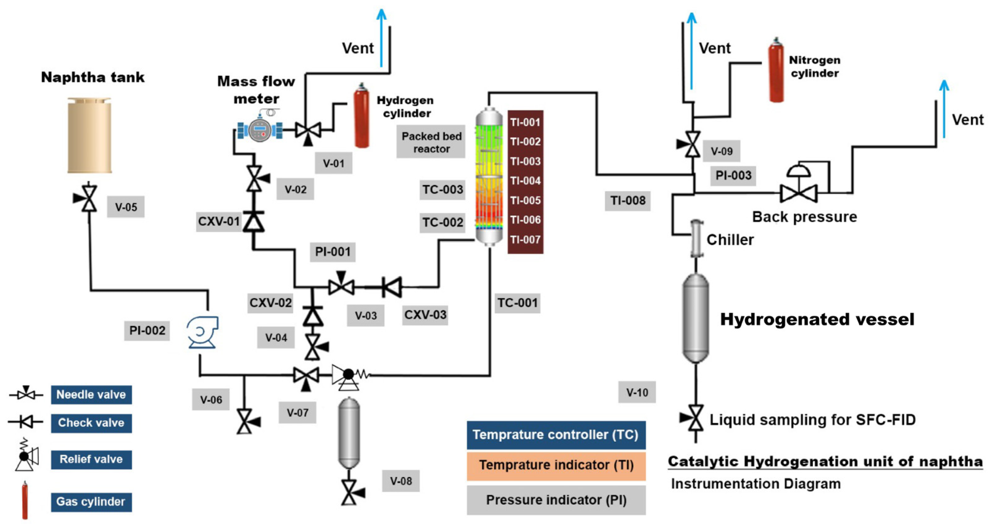
2.3. Pilot Plant Catalytic Tests

Reactivity experiments were conducted in a bench-scale pilot plant featuring an up-flow open tubular reactor [37,38], as illustrated in Figure 1. To prevent gum or deposit formation in the entrance lines, the naphtha and H2 feed lines were maintained at room temperature. The reactor temperature was varied at three levels (200, 250, and 280 °C) with a fixed H2 flow rate of 33 sccm. Naphtha flow rate control was achieved through an Isco pump, while a stainless steel up-flow reactor (1/2-inch internal diameter) was loaded with 10 g of 10 wt.% Mo2C/γ-Al2O3 catalyst. A thermocouple placed in the reactor’s packed bed wall, along with an Omega internal 7-point profile thermocouple, recorded temperature profiles. The latter had five points within the catalyst bed, and the other two were positioned in the middle of the upper and bottom packing material bed (SiC). The exit line of the reactor, set at room temperature, facilitated product stream condensation. Reactor pressure was regulated using a Swagelock back-pressure valve, set at 3.44 × 10⁶ Pa. Maintaining a desired weight hourly space velocity (WHSV = 0.43 h−1), the naphtha flow rate was controlled. WHSV was universally defined under pumping conditions, as expressed in Equation (1).
W H S V   [ h 1 ] = N a p h t h a   m a s s   f l o w   r a t e   ( g / h ) C a t a l y s t   m a s s   ( g )
The outlet gas stream flow rate was measured with a wet gas flow meter, and the gas collected in a sampling bag, which underwent analysis to ensure no hydrocarbons were entrained within the H2 effluent. The reaction product stream, after passing through a chiller, was collected for olefin quantification using supercritical fluid chromatography coupled with a flame ionization detector (SFC-FID) analysis. Liquid samples were analyzed online every 4 h using SFC-FID. The experiment that produced the least olefin content was then selected for another reactivity test in the presence of both H2 and steam to test the stability of catalyst under steam environment and to simulate the hydrogenation of naphtha produced from the hot separator in a CSC process. It is worth mentioning that in all experiments, the catalyst had to be activated prior to the naphtha hydrogenation tests. Then, 10 g of the precursor—10 wt.% Mo2C/γ-Al2O3 spheres were hydrothermally treated under atmospheric H2 flow of 120 sccm at 500 °C for 12 h.

2.4. Characterization Methods

Scanning electron microscopy coupled with energy dispersive X-ray (SEM-EDX, FEI, Calgary, AB, Canada) mapping was conducted on the 10 wt.% Mo2C/γ-Al2O3 catalyst. A minute quantity of the catalyst samples was affixed to an adhesive double-sided carbon tape secured on the metallic sample holder, which was subsequently tapped to eliminate excess powder. SEM images were captured using a field emission Quanta 250 electron microscope (FEI) with a voltage of 20 kV and a spot size of 3.0. Elemental identification on the material’s surface was achieved by employing an EDX detector.
For the determination of olefin content pre- and post-naphtha hydrogenation, supercritical fluid chromatography coupled with a flame ionization detector (SFC-FID; Selerity Technologies Inc., Salt Lake City, UT, USA) was employed. The SFC equipment, supplied by Selerity Technologies (Selerity Technologies Inc., Series 4000 SFC, Salt Lake City, UT, USA), utilized helium as the carrier gas. Initially, the ASTM D-5186 method [39] assessed the wt.% aromatics and non-aromatics in the feedstock by passing the sample through a packed silica column, as depicted in Figure S1 in the Supplementary Material section. ASTM D-6550 method [40] was also applied to separate saturates, aromatics, and olefins, utilizing silica and a 10% silver/silica packed column. A 1 mL liquid sample was collected, withdrawn by an auto-sampler, and injected into the SFC apparatus through a 60 nL Valco valve model. Quantification of saturates, aromatics, and olefins (SAO analysis) was executed using a flame ionization detector (FID), and data were collected and processed with EZChrom Elite data acquisition software, as shown in Figure S2 in the Supplementary Material.
Additionally, gas chromatography coupled with mass spectroscopy and a flame ionization detector (GC-MS-FID) was employed for paraffins, olefins, naphthenes, and aromatics (PONA) analysis of the feedstock. HP6890 series GC system (Hewlett Packard) with an integrated PONA column (length: 50 m, inner diameter: 200 µm, film thickness: 0.5 µm) and a flame ionization detector (FID) was utilized, following the ASTM D-5134 method [41], as shown in Table S1.
The metal contents of both JACOS Alberta bitumen and Nexen Naphtha were quantified using inductively coupled plasma (ICP) spectroscopy [34]. The samples were placed into appropriate Teflon vessels, and a mixture of hydrochloric and nitric acids was introduced. Subsequently, the vessels were sealed and subjected to heating in a MARS 6 microwave digestion apparatus manufactured by CEM for a complete cycle to extract and dissolve the metals present in the solids into the acid solution. The resulting solutions underwent ICP analysis using an Iris Intrepid II XDL spectrometer manufactured by Thermo Electron Corporation (Waltham, MA, USA) [34].

3. Results and Discussion

3.1. Characterization Results

Table 2 presents the physical properties and chemical composition of the investigated naphtha. It is evident that naphtha contains nearly 1 wt.% sulfur, a notably high value for naphthas. Group-type analysis, conducted for saturates, aromatics, and olefin content (wt.%) using SFC-FID, aligns closely with the findings derived from GC-MS-FID. Additionally, the concentration of heavy metals determined via inductively coupled plasma (ICP) in the naphtha was nearly negligible.
Furthermore, Figure 2 illustrates SEM images and EDX mapping for the 10 wt.% Mo2C/γ-Al2O3 spheres. The Mo2C phase exhibits uniform distribution across the Al2O3 spheres, with all constituent elements (Mo, C, Al, and O) observed on the catalyst surface. The carbide structure was also confirmed by X-ray diffraction, as depicted in Figure S3.

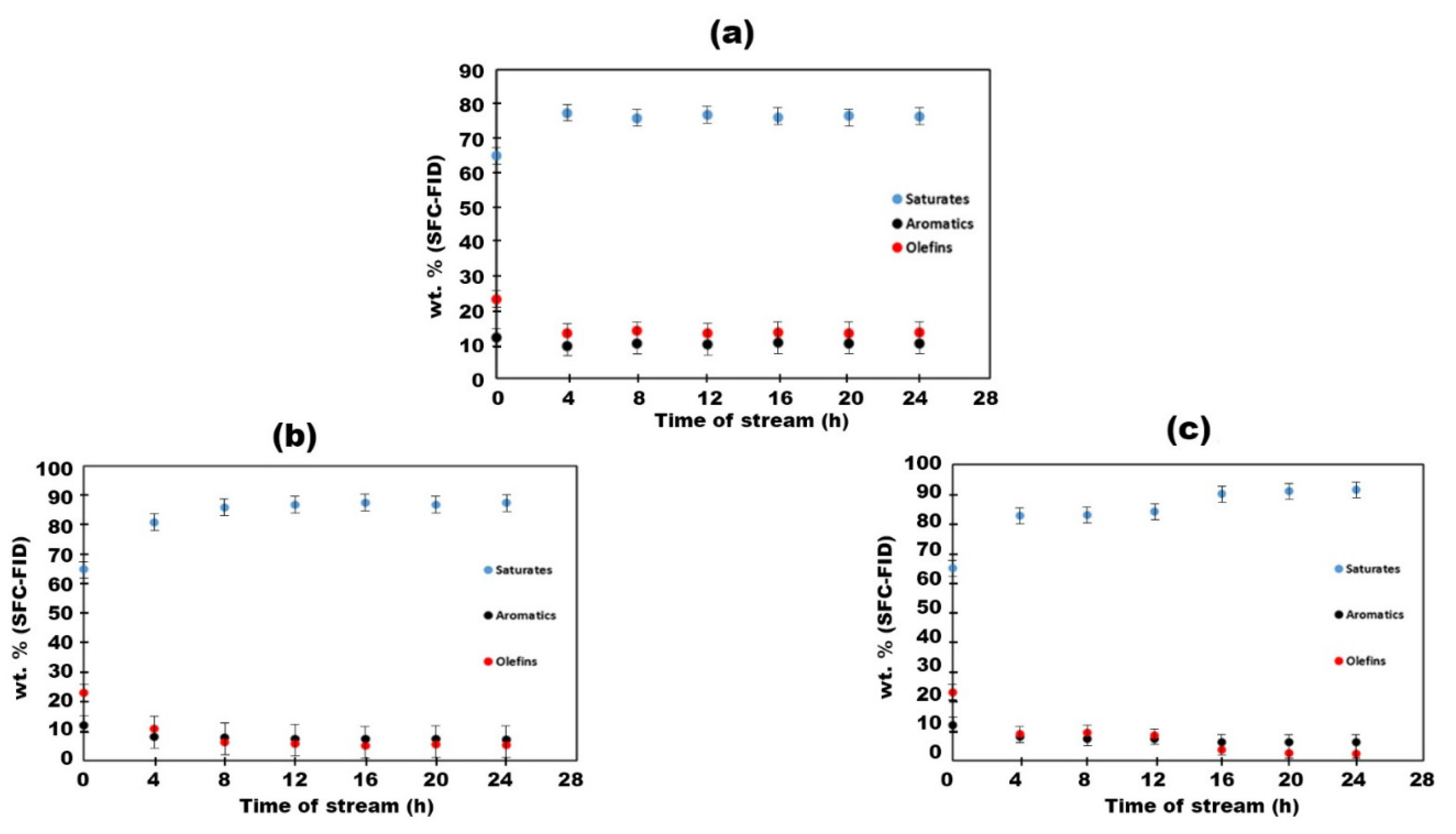
3.2. Catalytic Hydrogenation Tests of Naphtha on 10 wt.% Mo2C/γ-Al2O3 Spheres

The naphtha hydrogenation experiments conducted with 10 wt.% Mo2C/γ-Al2O3 catalyst demonstrated a notable efficacy in the removal of olefins. The alterations in saturates, aromatics, and olefin content (wt.%) after naphtha hydrogenation at 200 °C, 250 °C, and 280 °C are depicted in Figure 3. At 200 °C and after 4 h, a decrease in aromatics content from 12% to 10% was observed in Figure 3a, concomitant with a reduction in olefin content from 23% to 13%. Saturates, as anticipated, exhibited an increase from 65% to 76% because of the conversion of olefins to their saturate counterparts. Elevating the temperature to 250 °C resulted in a notable decline in aromatic content from 12% to 7%, affirming the activity of the 10 wt.% Mo2C/γ-Al2O3 spheres in aromatic hydrogenation at higher temperatures. Additionally, the quantity of olefins decreased from 23% to 5%, as indicated in Figure 3b. At the highest temperature (280 °C), the aromatic content exhibited no significant decrease, with a final content of approximately 6%, without signs of catalyst deactivation, as depicted in Figure 3c. A summary of all hydrogenations results over 10 wt.% Mo2C/γ-Al2O3 spheres is presented in Figure 4. Olefin content was reduced to 2.5% at 280 °C, indicating that incorporating this hydrogenated naphtha as a diluent in a ratio of 30 wt.% to bitumen would result in a total final olefin content of 0.75 wt.% (i.e., <1 wt.%), thereby meeting pipeline specifications for oil transportation. This aspect will be further discussed in the preceding section.

3.3. Incorporating Hydrogenated Naphtha as a Diluent into JACOS Athabasca Bitumen to Meet Pipeline Specifications

The naphtha product obtained from catalytic hydrogenation over 10 wt.% Mo2C/γ-Al2O3 spheres at 280 °C and 500 psig for 24 h was introduced into JACOS Athabasca bitumen to decrease its viscosity for pipeline conveyance. Figure 5 illustrates the linear regression analysis depicting the logarithmic relationship between viscosity (µ) and the wt.% of diluent (i.e., hydrogenated naphtha) added to the bitumen. At 7.5 °C, the final viscosity of the blend (i.e., dilbit) with 30 wt.% diluent was approximately 220 cP (i.e., <320 cP), meeting the specified criteria for dilbit transportation for Canadian pipelines. Moreover, the ultimate olefin content was <1 wt.%, as elaborated earlier in Section 3.2. The final p-value of the dilbit exceeded 1.8, and the API gravity value measured was 21.9.

3.4. Catalytic Hydrogenation Tests of Naphtha on 10 wt.% Mo2C/γ-Al2O3 Spheres in Presence of Steam Simulating the Hot Separator Stream

In the preceding sections, we evaluated the catalyst activity for olefin hydrogenation in naphtha, identifying 10 wt.% Mo2C/γ-Al2O3 spheres at 280 °C as yielding naphtha with minimal olefin content. Consequently, the same catalyst was selected for olefin hydrogenation under identical conditions (i.e., 280 °C and 3.44 × 10⁶ Pa) but with the introduction of steam. This facilitated the assessment of catalyst stability in a steam environment and the simulation of naphtha stream hydrogenation containing water, as encountered in the hot separator following the CSC process. Drawing from prior pilot plant investigations, a water/naphtha mass flow rate ratio of 5:3, reflective of typical CSC unit naphtha–water mixture compositions, was chosen. Despite the presence of steam in the reaction, olefin hydrogenation proceeded, resulting in a final olefin content reduction from 23% to 5%, with a concurrent aromatics content reaching 10%. The findings presented in Figure 6 unequivocally demonstrate the catalyst’s resilience to both steam and sulfur, endorsing its viability for commercialization as a selective hydrogenating catalyst for olefins in light petroleum distillates (e.g., naphthas and gasolines) under moderate temperatures, pressures, and steam conditions.

4. Conclusions

It has been demonstrated that our internally developed catalyst, synthesized via the sucrose route, effectively reduced the olefin content in an industrial naphtha feedstock. Spheres composed of 10 wt.% Mo2C/γ-Al2O3 exhibited notable catalytic activity and stability during olefin hydrogenation. The supported carbide catalyst achieved a final olefin content reduction to 2.5 wt.%, enabling compliance with pipeline specifications (i.e., <1 wt.% olefins) for oil pumping by incorporating the resulting hydrogenated naphtha as a diluent in Athabasca bitumen at a 30 wt.% ratio. Furthermore, the catalyst exhibited robust tolerance to sulfur present in the naphtha for a duration of 96 h, manifesting no indications of catalyst deactivation. Lastly, the supported molybdenum carbide demonstrated exceptional stability and high activity in steam environments, suggesting its potential utility for hydrogenating naphtha streams containing water derived from the hot separator post-CSC process.

Supplementary Materials

The following supporting information can be downloaded at: https://www.mdpi.com/article/10.3390/ma17102278/s1, Figure S1. Normalized supercritical fluid chromatography (SFC) chromatogram for Nexen naphtha feedstock using ASTM D-5186 method. Figure S2. Normalized supercritical fluid chromatography (SFC) chromatogram for Nexen naphtha feedstock using ASTM D-6550 method. Table S1. Olefinic molecules present in Nexen naphtha, as determined by GC-MS-FID (ASTM D-5134). Figure S3. X-ray diffraction (XRD) diffractogram of the activated Mo2C prepared by the sucrose route.

Author Contributions

Conceptualization, H.A.A. and M.E.H.E.N.; methodology, M.S.A.; validation, P.G.C., M.S.A. and Z.A.P.; formal analysis, K.O.S.; investigation, K.O.S.; resources, H.A.A.; data curation, H.A.A.; writing—original draft preparation, A.E.; writing—review and editing, A.E.; visualization, K.O.S.; supervision, K.O.S.; project administration, K.O.S. All authors have read and agreed to the published version of the manuscript.

Funding

This research was funded by Alberta Innovates—Energy and Environment Solutions (AIEES), Natural Sciences and Engineering Research Council of Canada (NSERC), Nexen Industrial Research Chair in Catalysis for Bitumen Upgrading, Queen Elizabeth II PhD fellowship and the Schulich School of Engineering at the University of Calgary, Canadian Foundation for Innovation and the Alberta Science and Research Authority.

Institutional Review Board Statement

Not applicable.

Informed Consent Statement

Not applicable.

Data Availability Statement

Data are contained within the article.

Acknowledgments

The authors want to acknowledge Alberta Innovates—Energy and Environment Solutions (AIEES) for the financial support provided through the Natural Sciences and Engineering Research Council of Canada (NSERC), Nexen Industrial Research Chair in Catalysis for Bitumen Upgrading, Queen Elizabeth II PhD fellowship and the Schulich School of Engineering at the University of Calgary. Special thanks to Chris Debuhr for giving access to the Instrumentation Facility for Analytical Electron Microscopy. Special thanks to Tobias Fürstenhaupt for access to the Microscopy and Imaging Facility of the Health Science Centre at the University of Calgary, which receives support from the Canadian Foundation for Innovation and the Alberta Science and Research Authority. The authors thank Engineer Mohamed Saeed Elgamasy for the artwork provided.

Conflicts of Interest

Author Zahra Asgar Pour was employed by the company Kisuma Chemicals. Author Mohammed S. Alnafisah was employed by the company King Abdulaziz City for Science and Technology (KACST). The remaining authors declare that the research was conducted in the absence of any commercial or financial relationships that could be construed as a potential conflict of interest.

References

  1. Speight, J.G. The Chemistry and Technology of Petroleum, 5th ed.; CRC Press, Taylor and Francis Group: Boca Raton, FL, USA, 2014; ISBN 978-1-4398-7389. [Google Scholar]
  2. Speight, J.G. Heavy and Extra-Heavy Oil Upgrading Technologies; Elsevier: Amsterdam, The Netherlands, 2013; ISBN 978-0-12-404570-5. [Google Scholar]
  3. Ghashghaee, M.; Shirvani, S. Two-Step Thermal Cracking of an Extra-Heavy Fuel Oil: Experimental Evaluation, Characterization, and Kinetics. Ind. Eng. Chem. Res. 2018, 57, 7421–7430. [Google Scholar] [CrossRef]
  4. Yeletsky, P.M.; Zaikina, O.O.; Sosnin, G.A.; Kukushkin, R.G.; Yakovlev, V.A. Heavy Oil Cracking in the Presence of Steam and Nanodispersed Catalysts Based on Different Metals. Fuel Process. Technol. 2020, 199, 106239. [Google Scholar] [CrossRef]
  5. Qureshi, Z.S.; Siddiqui, M.A.; Tanimu, A.; Aitani, A.; Akah, A.C.; Xu, Q.; AlHerz, M. Steam Catalytic Cracking of Crude Oil over Novel Hierarchical Zeolite–Containing Mesoporous Silica–Alumina Core-Shell Catalysts. J. Anal. Appl. Pyrolysis 2022, 166, 105621. [Google Scholar] [CrossRef]
  6. Eletskii, P.M.; Mironenko, O.O.; Kukushkin, R.G.; Sosnin, G.A.; Yakovlev, V.A. Catalytic Steam Cracking of Heavy Oil Feedstocks: A Review. Catal. Ind. 2018, 10, 185–201. [Google Scholar] [CrossRef]
  7. Trujillo-Ferrer, G. Thermal and Catalytic Steam Reactivity Evaluation of Athabasca Vacuum Gasoil. Master’s Thesis, University of Calgary, Calgary, AB, Canada, 2008. [Google Scholar]
  8. Pereira-Almao, P. Systems and Methods for Catalytic Steam Cracking of Non-Asphaltene Containing Heavy Hydrocarbons. U.S. Patent US20130015100A1, 7 February 2017. [Google Scholar]
  9. Raseev, S. Thermal and Catalytic Processes in Petroleum Refining, 1st ed.; CRC Press; Marcel Dekker: New York, NY, USA, 2003; ISBN 978-0-367-39544-5. [Google Scholar]
  10. Pereira-Almao, P. Steam Conversion Process and Catalyst. U.S. Patent US5885441A, 23 March 1999. [Google Scholar]
  11. Pereira, R.C.C.; Pasa, V.M.D. Effect of Mono-Olefins and Diolefins on the Stability of Automotive Gasoline. Fuel 2006, 85, 1860–1865. [Google Scholar] [CrossRef]
  12. Gholami, Z.; Gholami, F.; Tišler, Z.; Vakili, M. A Review on the Production of Light Olefins Using Steam Cracking of Hydrocarbons. Energies 2021, 14, 8190. [Google Scholar] [CrossRef]
  13. Nagpal, J.M.; Joshi, G.C.; Singh, J.; Rastogi, S.N. Gum Forming Olefinic Precursors in Motor Gasoline, A Model Compound Study. Fuel Sci. Technol. Int. 1994, 12, 873–894. [Google Scholar] [CrossRef]
  14. Fan, Z.; Rahimi, P.; Alem, T.; Eisenhawer, A.; Arboleda, P. Fouling Characteristics of Hydrocarbon Streams Containing Olefins and Conjugated Olefins. Energy Fuels 2011, 25, 1182–1190. [Google Scholar] [CrossRef]
  15. Glaude, P.A.; Fournet, R.; Warth, V.; Molière, M. Stability of Olefin-Containing Process Gases as an Alternative Fuel for Gas Turbines. Ind. Eng. Chem. Res. 2005, 44, 4212–4220. [Google Scholar] [CrossRef]
  16. Smith, L.A. Process to Hydrodesulfurize Pyrolysis Gasoline. U.S. Patent 8663458 B2, 3 April 2014. [Google Scholar]
  17. Gray, M.R.; McCaffrey, W.C. Role of Chain Reactions and Olefin Formation in Cracking, Hydroconversion, and Coking of Petroleum and Bitumen Fractions. Energy Fuels 2002, 16, 756–766. [Google Scholar] [CrossRef]
  18. Levy, R.B.; Boudart, M. Platinum-Like Behavior of Tungsten Carbide in Surface Catalysis. Science 1973, 181, 547–549. [Google Scholar] [CrossRef] [PubMed]
  19. Lee, J.S.; Yeom, M.H.; Park, K.Y.; Nam, I.-S.; Chung, J.S.; Kim, Y.G.; Moon, S.H. Preparation and Benzene Hydrogenation Activity of Supported Molybdenum Carbide Catalysts. J. Catal. 1991, 128, 126–136. [Google Scholar] [CrossRef]
  20. Mamède, A.S.; Giraudon, J.-M.; Löfberg, A.; Leclercq, L.; Leclercq, G. Hydrogenation of Toluene over β-Mo2C in the Presence of Thiophene. Appl. Catal. A Gen. 2002, 227, 73–82. [Google Scholar] [CrossRef]
  21. Espinoza-Monjardín; Cruz-Reyes, J.; Del Valle-Granados, M.; Flores-Aquino, E.; Avalos-Borja, M.; Fuentes-Moyado, S. Synthesis, Characterization and Catalytic Activity in the Hydrogenation of Cyclohexene with Molybdenum Carbide. Catal. Lett. 2008, 120, 137–142. [Google Scholar] [CrossRef]
  22. Frauwallner, M.-L.; López-Linares, F.; Lara-Romero, J.; Scott, C.E.; Ali, V.; Hernández, E.; Pereira-Almao, P. Toluene Hydrogenation at Low Temperature Using a Molybdenum Carbide Catalyst. Appl. Catal. A Gen. 2011, 394, 62–70. [Google Scholar] [CrossRef]
  23. Claridge, J.B.; York, A.P.E.; Brungs, A.J.; Marquez-Alvarez, C.; Sloan, J.; Tsang, S.C.; Green, M.L.H. New Catalysts for the Conversion of Methane to Synthesis Gas: Molybdenum and Tungsten Carbide. J. Catal. 1998, 180, 85–100. [Google Scholar] [CrossRef]
  24. Choi, J.G.; Brenner, J.R.; Thompson, L.T. Pyridine Hydrodenitrogenation over Molybdenum Carbide Catalysts. J. Catal. 1995, 154, 33–40. [Google Scholar] [CrossRef]
  25. Aegerter, P.A.; Quigley, W.W.C.; Simpson, G.J.; Ziegler, D.D.; Logan, J.W.; McCrea, K.R.; Glazier, S.; Bussell, M.E. Thiophene Hydrodesulfurization over Alumina-Supported Molybdenum Carbide and Nitride Catalysts: Adsorption Sites, Catalytic Activities, and Nature of the Active Surface. J. Catal. 1996, 164, 109–121. [Google Scholar] [CrossRef]
  26. Oyama, S.T.; Schlatter, J.C.; Metcalfe, J.E.I.; Lambert, J.M., Jr. Preparation and Characterization of Early Transition Metal Carbides and Nitrides. Ind. Eng. Chem. Res. 1988, 27, 1639–1648. [Google Scholar] [CrossRef]
  27. Lee, J.S.; Boudart, M. Hydrodesulfurization of Thiophene over Unsupported Molybdenum Carbide. Appl. Catal. 1985, 19, 207–210. [Google Scholar] [CrossRef]
  28. Ramanathan, S.; Oyama, S.T. New Catalysts for Hydroprocessing: Transition Metal Carbides and Nitrides. J. Phys. Chem. 1995, 99, 16365–16372. [Google Scholar] [CrossRef]
  29. Dolce, G.M.; Savage, P.E.; Thompson, L.T. Hydrotreatment Activities of Supported Molybdenum Nitrides and Carbides. Energy Fuels 1997, 11, 668–675. [Google Scholar] [CrossRef]
  30. Dhandapani, B.; St. Clair, T.; Oyama, S.T. Simultaneous Hydrodesulfurization, Hydrodeoxygenation, and Hydrogenation with Molybdenum Carbide. Appl. Catal. A Gen. 1998, 168, 219–228. [Google Scholar] [CrossRef]
  31. Patel, M.; Subrahmanyam, J. Synthesis of Nanocrystalline Molybdenum Carbide (Mo2C) by Solution Route. Mater. Res. Bull. 2008, 43, 2036–2041. [Google Scholar] [CrossRef]
  32. Sebakhy, K.O.; Vitale, G.; Hassan, A.; Pereira-Almao, P. New Insights into the Kinetics of Structural Transformation and Hydrogenation Activity of Nano-Crystalline Molybdenum Carbide. Catal. Lett. 2018, 148, 904–923. [Google Scholar] [CrossRef]
  33. Ahmadi Khoshooei, M.; Vitale, G.; Carbognani, L.; Pereira-Almao, P. Evidence of Water Dissociation and Hydrogenation on Molybdenum Carbide Nanocatalyst for Hydroprocessing Reactions. Catal. Sci. Technol. 2022, 12, 6184–6194. [Google Scholar] [CrossRef]
  34. ASTM D7169-16; Standard Test Method for Boiling Point Distribution of Samples with Residues Such as Crude Oils and Atmospheric and Vacuum Residues by High Temperature Gas Chromatography. ASTM: West Conshohocken, PA, USA, 2016.
  35. Carbognani, L.; Roa-Fuentes, L.C.; Diaz, L.; Lopez-Linares, F.; Vasquez, A.; Pereira-Almao, P.; Haghigat, P.; Maini, B.B.; Spencer, R.J. Monitoring Bitumen Upgrading, Bitumen Recovery, and Characterization of Core Extracts by Hydrocarbon Group-Type SARA Analysis. Pet. Sci. Technol. 2010, 28, 632–645. [Google Scholar] [CrossRef]
  36. ASTM D664-11a(2017); Standard Test Method for Acid Number of Petroleum Products by Potentiometric Titration. ASTM: West Conshohocken, PA, USA, 2017.
  37. Sebakhy, K.O.; Vitale, G.; Pereira-Almao, P.A. Dispersed Ni-Doped Aegirine Nanocatalysts for the Selective Hydrogenation of Olefinic Molecules. ACS Appl. Nano Mater. 2018, 1, 6269–6280. [Google Scholar] [CrossRef]
  38. Sebakhy, K.O.; Vitale, G.; Pereira-Almao, P. Production of Highly Dispersed Ni within Nickel Silicate Materials with the MFI Structure for the Selective Hydrogenation of Olefins. Ind. Eng. Chem. Res. 2019, 58, 8597–8611. [Google Scholar] [CrossRef]
  39. ASTM D5186-03; Standard Test Method for Determination of Aromatic Content and Polynuclear Aromatic Content of Diesel Fuels and Aviation Turbine Fuels by Supercritical Fluid Chromatography. ASTM: West Conshohocken, PA, USA, 2009.
  40. ASTM D6550-00; Standard Test Method for Determination of Olefin Content of Gasolines by Supercritical-Fluid Chromatography. ASTM: West Conshohocken, PA, USA, 2000.
  41. Badoni, R.P.; Bhagat, S.D.; Joshi, G.C. Analysis of Olefinic Hydrocarbons in Cracked Petroleum Stocks: A Review. Fuel 1992, 71, 483–491. [Google Scholar] [CrossRef]
Scheme 1. Representation of olefin elimination in naphtha streams containing water and sulfur. A process simulating the hot separator stream.
Materials 17 02278 sch001
Figure 1. Piping and instrumentation diagram of the pilot plant hydrogenation unit used for olefin hydrogenation tests on industrial naphtha feedstock.
Materials 17 02278 g001
Figure 2. Scanning electron microscope–energy dispersive X-ray (SEM-EDX) mapping images for 10 wt.% Mo2C/γ-Al2O3 spheres.
Materials 17 02278 g002
Figure 3. Saturates, aromatics, and olefins time–supercritical fluid chromatography (SFC) profiles during the hydrogenation of naphtha over 10 wt.% Mo2C/γ-Al2O3 spheres at 3.44 × 10⁶ Pa, 33 sccm H2 flow and WHSV = 0.43 h−1: (a) 200 °C, (b) 250 °C, and (c) 280 °C.
Materials 17 02278 g003
Figure 4. Bar chart at the tested temperatures for the final saturates, aromatics, and olefin content (wt.%) in naphtha after hydrogenation over 10 wt.% Mo2C/γ-Al2O3 spheres for 24 h (pressure = 3.44 × 10⁶ Pa, WHSV = 0.43 h−1, H2 flow = 33 sccm).
Materials 17 02278 g004
Figure 5. Linear plot for log (µ) at 7.5 °C versus wt.% diluent added to JACOS bitumen.
Materials 17 02278 g005
Figure 6. Saturates, aromatics, and olefins time–supercritical fluid chromatography (SFC) profiles during the hydrogenation of naphtha in the presence of steam over 10 wt.% Mo2C/γ-Al2O3 spheres at 280 °C, 3.44 × 10⁶ Pa, 33 sccm H2 flow and WHSV = 0.43 h−1. (Water/naphtha mass flow rate ratio = 5:3).
Materials 17 02278 g006
Table 1. JACOS Athabasca Bitumen chemical and physical properties.
Analysis BitumenJACOS Athabasca
API gravity9.5
Initial boiling point (°C) by simulated distillation a171
wt.% residue > 545 °C by simulated distillation a50
viscosity at 7.5 °C [cP]444,324
water content [wt.%]0.4
carbon [wt.%]83.5
hydrogen [wt.%]10.6
sulfur [wt.%]4.8
nitrogen [wt.%]0.4
Mo [ppm]12.1
Ni [ppm]78.7
V [ppm]191
W [ppm]1
Fe [ppm]10
SARA bsaturates [wt.%]15
aromatics [wt.%]48
resins [wt.%]25
asphaltenes-C7 [wt.%]12
Total acid number (TAN) c2.6
a Determined using ASTM D-7169 method [34]. b Determined as in Carbognani et al. [35]. c Determined using ASTM-D664 method [36].
Table 2. Physical and chemical composition of naphtha feedstock.
Nexen’s Cracked NaphthaPhysical Properties and Chemical Composition
Density at 20 °C (g/cm3)0.784
Initial boiling point (°C) by SIMDIST−11 °C
Final boiling point (°C) by SIMDIST270 °C
Sulfur content (ppm)10,700 (~1 wt.%)
Metal analysis (ICP)4.5 ppm Fe
SFC-FID analysis (wt.%)/ASTM D-6550 [40]65% saturates, 12% aromatics, 23% olefins
SFC-FID analysis (wt.%)/ASTM D-5186 [39]90% non-aromatics, 10% aromatics
GC-FID-MS analysis (wt.%) [41]66% saturates, 11% aromatics, 23% olefins
Disclaimer/Publisher’s Note: The statements, opinions and data contained in all publications are solely those of the individual author(s) and contributor(s) and not of MDPI and/or the editor(s). MDPI and/or the editor(s) disclaim responsibility for any injury to people or property resulting from any ideas, methods, instructions or products referred to in the content.

