
DoE Approach to Setting Input Parameters for Digital 3D Printing of Concrete for Coarse Aggregates up to 8 mm


Abstract
1. Introduction
2. Literature Review—Theoretical Framework
2.1. Technical Equipment and Material Selection
- Material Parameters
2.2. Setting of Printing Parameters
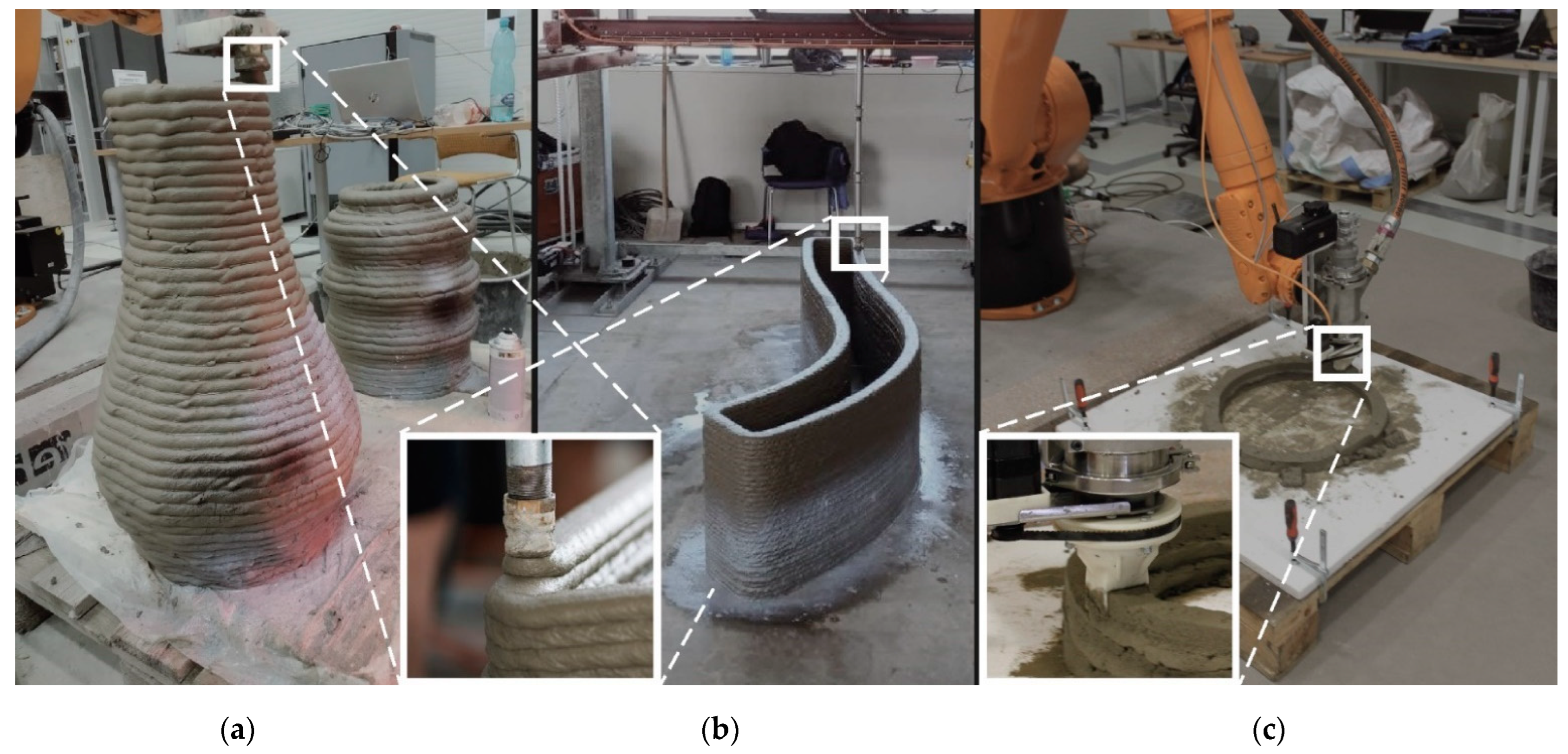
- Printing Geometry
2.3. Simulation Prior to Printing
2.4. Novel Contribution of This Study
3. Methods of Printing Design
3.1. Identification of Influencing Factors and Their Scaling
- Material properties (uncontrollable influencing factor)
- Young’s modulus of elasticity was determined by calculating the measured values σn and Ɛ at various times ranging from 20 to 45 min after wet mixing at 5 min intervals. For each time, three values were obtained, and the average value was calculated. A simple linear regression was used to determine the time evolution of Young’s modulus, where the independent variable is the time course, and the dependent variable is Young’s modulus [7].
- The cohesion behavior is time-dependent, the same for Young´s modulus, for material with coarse aggregate, which was obtained by evaluation of Shear box test. Cylindrical specimens were tested at the appropriate time intervals: from 20 min after wet mixing to 120 min at approximately 20-min intervals, with a horizontal displacement of 12 mm and nominal normal loads 5, 15, and 25 N plus the dead weight of a part of the specimen above the shear zone. The mixture with a coarse aggregate exhibited bilinear behavior, which would be difficult to implement in simulations. Therefore, the cohesion value was chosen as a constant based on the mean of all measurement values resulting in [7]. Nota bene: the authors of study [24] recommended modelling cohesion behavior with constant and default settings.
- The internal friction angle of a material is related to cohesion due to the Mohr—Coulomb failure criterion, where the friction angle indicates the slope of the cohesion course; therefore, the average value is derived from measured values in previous authors’ studies [7], where the value is significantly higher for aggregate material compared to soft grained material.
- The material’s plastic behaviour can be analysed using the dilatancy angle; however, in 3DCP technology, the occurrence of plastic deformation typically results in print failure. Consequently, it is of little significance in terms of 3D printing, and its average value, based on a review of literature especially in study [31] where this phenomenon was discussed, was adopted.
- The Poisson’s ratio indicates the proportional transformation of a specimen under load, where the value of Poisson´s constant for fresh concrete was determined to be 0.3. Based on the literature review and the behaviour of Mix 1, the value was kept unchanged.
- Print geometry (controllable influencing factor)
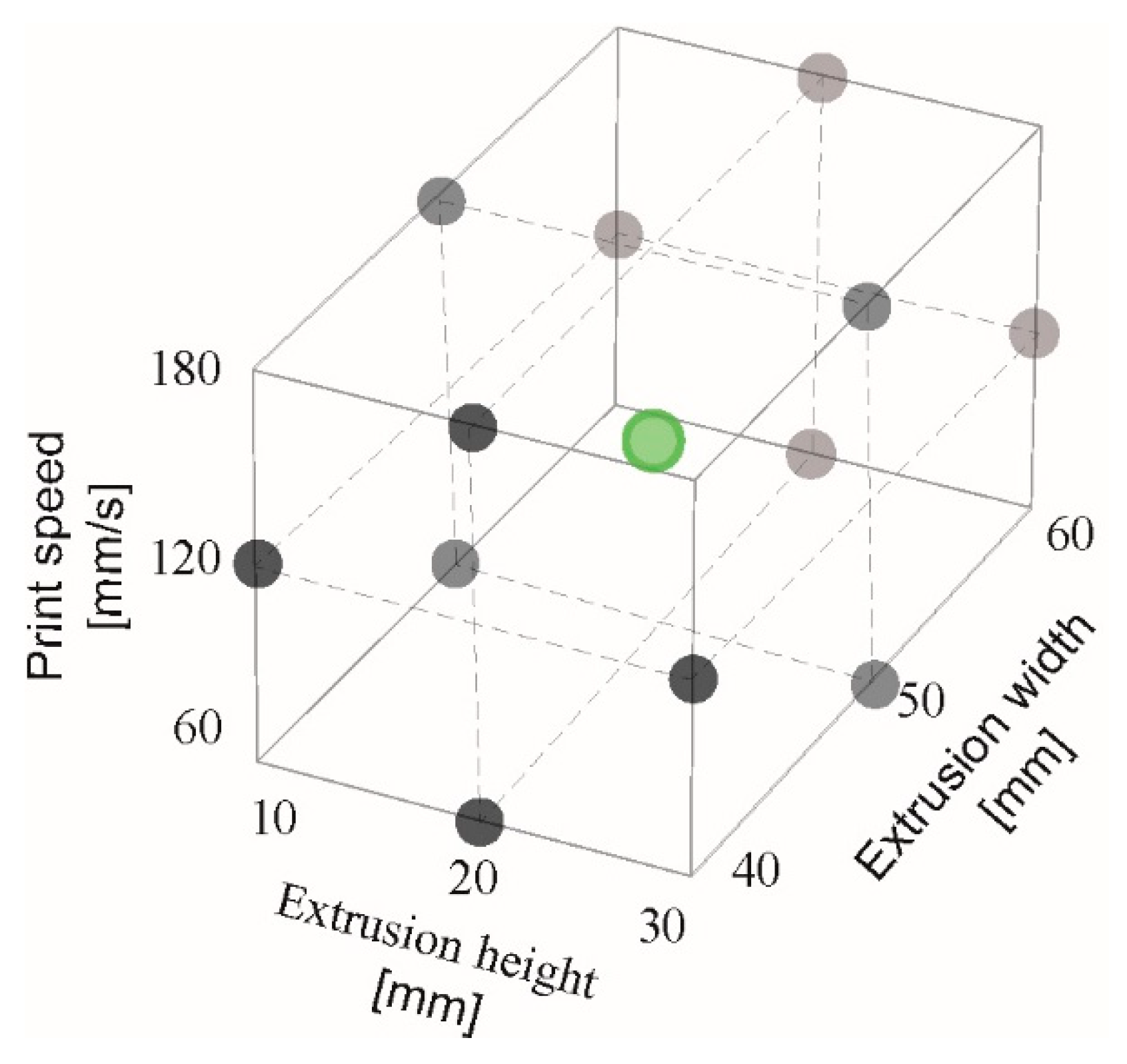
3.2. Selection of Combinations for Performing the Simulation
3.3. Simulation Conditions
4. Results and Discussion
5. Conclusions
- The technology of 3D concrete printing is currently facing multidimensional challenges that need to be overcome. From a practical standpoint, the trial-and-error approach is a process that requires a great deal of energy, materials, time, and human resources. It is also very costly for numerical simulations, an implementation on the order of hours/days for the CPU, depending on the complexity of the printed object. Therefore, it is important to reduce the number of simulations required to explore the entire design space using a DOE (Design of Experiment) approach.
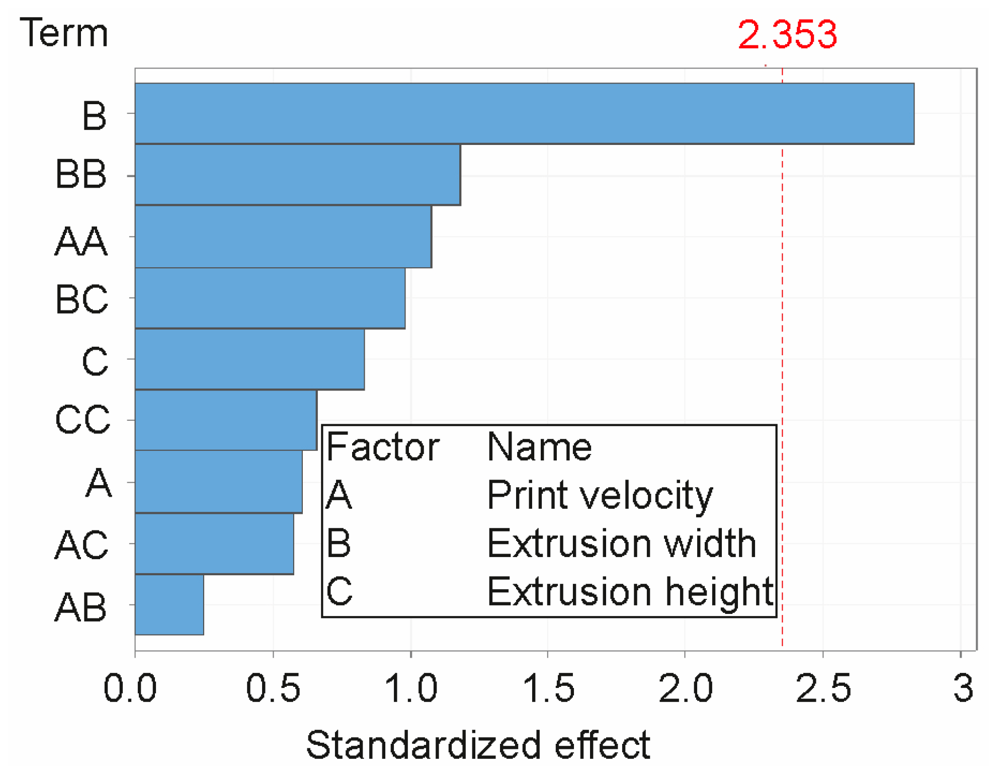
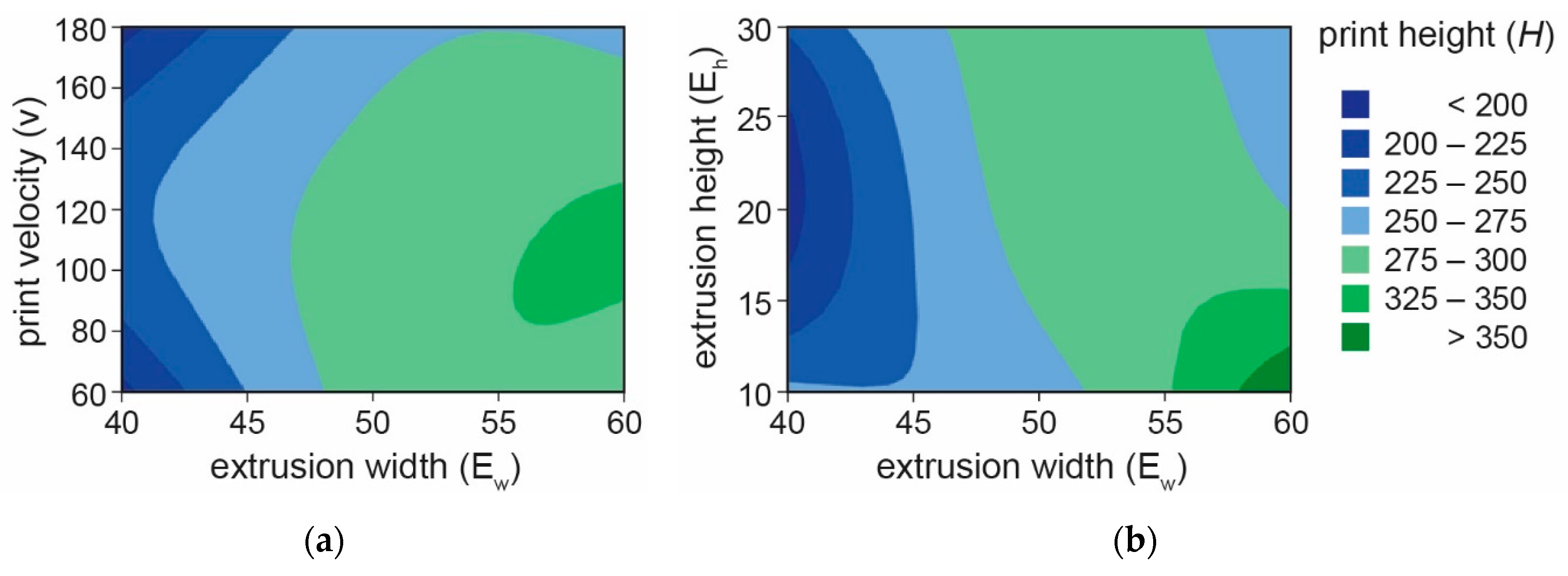
- Extrusion width is a significant factor; other factors and their combinations are statistically insignificant according to the tests. The input combinations used for the simulation resulted in a theoretically correct combination of process parameters and were based on the standardized effect at significance level α = 0.1 (0.066 < 0.1).
- A non-monotonic relationship was found for the parameters of the printing process, namely layer height, layer width, and printing speed.
- The prediction of buildability can thus be considered a non-trivial problem.
- General Findings
- Most of the studies did not provide a complete material model that could be the new established standard in the 3DCP technology research community. This would avoid an unnecessary waste of human resources and raw materials in the case of follow-up research.
- It would be useful to include other parameters in geometry and material to the DoE, but this leads to a huge number of simulations, which is not realistic. The goal is to be able to control all parameters, where it seems best to use machine learning.
- Future Work
- The behavior of coarse aggregate in the fresh state needs to be further investigated. The sensitivity of buildability needs to be studied in terms of the natural (irreducible) variability of material parameters (up to 20% natural variability in concrete) to avoid the occurrence of imperfections due to the scale and complexity of the print geometry. In addition, controllable parameters that can compensate for the above irreducible variability should be considered to ensure exposure even under the existing uncertainty conditions. In particular, bio-inspired geometries, generative lattice structures, topologically optimised structures, etc., fulfil these sub-goals.
- In the future, printing shape-complex geometries will require a different approach to the strategy and methods used to generate print trajectories. Currently, they are widely used, especially in the 3D printing of polymer-based materials. The use of advanced printing methods will introduce a new dimension of uncertainty, leading to entirely new challenges to consider and solve. This is where the development of machine vision and machine learning lends itself to the evaluation of print geometry, where the parameter of perimetric complexity can be combined with the cross-sectional area of the 3D printed structure and used to describe the geometry of the layers of the printed body.
- Based on the above, it will be possible to create a robust formulation of a digital twin for the 3D concrete/structure printing process and the associated digital concrete model.
Author Contributions
Funding
Data Availability Statement
Acknowledgments
Conflicts of Interest
References
- Agustí-Juan, I.; Müller, F.; Hack, N.; Wangler, T.; Habert, G. Potential benefits of digital fabrication for complex structures: Environmental assessment of a robotically fabricated concrete wall. J. Clean. Prod. 2017, 154, 330–340. [Google Scholar] [CrossRef]
- United Nations Environment Programme. Towards a Zero-Emissions, Efficient and Resilient Buildings and Construction Sector. 2019 Global Status Report. 2019. Available online: https://www.unep.org/resources/publication/2019-global-status-report-buildings-and-construction-sector (accessed on 28 September 2021).
- Buswell, R.A.; De Silva, W.R.L.; Jones, S.Z.; Dirrenberger, J. 3D printing using concrete extrusion: A roadmap for research. Cem. Concr. Res. 2018, 112, 37–49. [Google Scholar] [CrossRef]
- du Plessis, A.; Babafemi, A.J.; Paul, S.C.; Panda, B.; Tran, J.P.; Broeckhoven, C. Biomimicry for 3D concrete printing: A review and perspective. Addit. Manuf. 2021, 38, 101823. [Google Scholar] [CrossRef]
- Lim, S.; Buswell, R.; Le, T.; Austin, S.; Gibb, A.; Thorpe, T. Developments in construction-scale additive manufacturing processes. Autom. Constr. 2012, 21, 262–268. [Google Scholar] [CrossRef]
- De Schutter, G.; Lesage, K.; Mechtcherine, V.; Nerella, V.N.; Habert, G.; Agusti-Juan, I. Vision of 3D printing with concrete—Technical, economic and environmental potentials. Cem. Concr. Res. 2018, 112, 25–36. [Google Scholar] [CrossRef]
- Vespalec, A.; Podroužek, J.; Boštík, J.; Míča, L.; Koutný, D. An experimental study on time dependent behaviour of coarse aggregate concrete mixture for 3D Construction Printing. Construction and Building materials. Constr. Build. Mater. 2023, 376, 130999. [Google Scholar] [CrossRef]
- Khan, M.S.; Sanchez, F.; Zhou, H. 3-D printing of concrete: Beyond horizons. Cem. Concr. Res. 2020, 133, 106070. [Google Scholar] [CrossRef]
- Zhu, B.; Pan, J.; Nematollahi, B.; Zhou, Z.; Zhang, Y.; Sanjayan, J. Development of 3D printable engineered cementitious composites with ultra-high tensile ductility for digital construction. Mater. Des. 2019, 181, 108088. [Google Scholar] [CrossRef]
- Souza, M.T.; Ferreira, I.M.; de Moraes, E.G.; Senff, L.; de Oliveira, A.P.N. 3D printed concrete for large-scale buildings: An overview of rheology, printing parameters, chemical admixtures, reinforcements, and economic and environmental prospects. J. Build. Eng. 2020, 32, 101833. [Google Scholar] [CrossRef]
- Duballet, R.; Baverel, O.; Dirrenberger, J. Classification of building systems for concrete 3D printing. Autom. Constr. 2017, 83, 247–258. [Google Scholar] [CrossRef]
- Fernandes, G.; Feitosa, L. Impact of Contour Crafting on Civil Engineering. Int. J. Eng. Res. Technol. IJERT 2015, 4, 628–632. [Google Scholar]
- Meurer, M.; Classen, M. Mechanical Properties of Hardened 3D Printed Concretes and Mortars—Development of a Consistent Experimental Characterization Strategy. Materials 2021, 14, 752. [Google Scholar] [CrossRef]
- 3D Concrete Printing. Available online: https://www.ice.cz/en/ice-coral (accessed on 1 February 2021).
- Vespalec, A.; Novák, J.; Kohoutková, A.; Vosynek, P.; Podroužek, J.; Škaroupka, D.; Zikmund, T.; Kaiser, J.; Paloušek, D. Interface Behavior and Interface Tensile Strength of a Hardened Concrete Mixture with a Coarse Aggregate for Additive Manufacturing. Materials 2020, 13, 5147. [Google Scholar] [CrossRef] [PubMed]
- Mechtcherine, V.; Nerella, V.N.; Will, F.; Näther, M.; Otto, J.; Krause, M. On-site, large-scale, monolithic 3D concrete printing. Construction Printing Technology. Constr. Print. Technol. 2020, 2, 14–22. [Google Scholar]
- Bong, S.H.; Nematollahi, B.; Nazari, A.; Xia, M.; Sanjayan, J. Method of Optimisation for Ambient Temperature Cured Sustainable Geopolymers for 3D Printing Construction Applications. Materials 2019, 16, 902. [Google Scholar] [CrossRef] [PubMed]
- Panda, B.; Tan, M.J. Experimental study on mix proportion and fresh properties of fly ash based geopolymer for 3D concrete printing. Ceram. Int. 2018, 44, 10258–10265. [Google Scholar] [CrossRef]
- Dey, D.; Srinivas, D.; Panda, B.; Suraneni, P.; Sitharam, T. Use of industrial waste materials for 3D printing of sustainable concrete: A review. J. Clean. Prod. 2022, 340, 130749. [Google Scholar] [CrossRef]
- Watari, T.; Cao, Z.; Hata, S.; Nansai, K. Efficient use of cement and concrete to reduce reliance on supply-side technologies for net-zero emissions. Nat. Commun. 2022, 13, 4158. [Google Scholar] [CrossRef]
- Panda, B.; Unluer, C.; Tan, M.J. Investigation of the rheology and strength of geopolymer mixtures for extrusion-based 3D printing. Cem. Concr. Compos. 2018, 94, 307–314. [Google Scholar] [CrossRef]
- Chen, Y.; Veer, F.; Copuroglu, O. A critical review of 3D concrete printing as a low CO2 concrete approach. Heron 2017, 62, 167–194. [Google Scholar] [CrossRef]
- Wang, D.; Zhu, J.; He, F. CO2 carbonation-induced improvement in strength and microstructure of reactive MgO-CaO-fly ash-solidified soils. Constr. Build. Mater. 2019, 229, 116914. [Google Scholar] [CrossRef]
- Vantyghem, G.; Ticho, O.; Wouter, D.C. FEM modelling techniques for simulation of 3D concrete printing. arXiv 2020, arXiv:2009.06907. [Google Scholar] [CrossRef]
- Mai, I.; Brohmann, L.; Freund, N.; Gantner, S.; Kloft, H.; Lowke, D.; Hack, N. Large Particle 3D Concrete Printing—A Green and Viable Solution. Materials 2021, 14, 6125. [Google Scholar] [CrossRef]
- Carneau, P.; Mesnil, R.; Roussel, N.; Baverel, O. Additive manufacturing of cantilever-From masonry to concrete 3D printing. Autom. Constr. 2020, 116, 103184. [Google Scholar] [CrossRef]
- Vantyghem, G.; Ooms, T.; De Corte, W. VoxelPrint: A Grasshopper plug-in for voxel-based numerical simulation of concrete printing. Autom. Constr. 2021, 122, 103469. [Google Scholar] [CrossRef]
- Chang, Z.; Liang, M.; Xu, Y.; Schlangen, E.; Šavija, B. 3D concrete printing: Lattice modeling of structural failure considering damage and deformed geometry. Cem. Concr. Compos. 2022, 133, 104719. [Google Scholar] [CrossRef]
- Khan, S.A.; Koç, M. Buildability Analysis of 3D Concrete Printing Process: A Parametric Study Using Design of Experiment Approach. Processes 2023, 11, 782. [Google Scholar] [CrossRef]
- Suiker, A.; Wolfs, R.; Lucas, S.; Salet, T. Elastic buckling and plastic collapse during 3D concrete printing. Cem. Concr. Res. 2020, 135, 106016. [Google Scholar] [CrossRef]
- Wolfs, R.J.M.; Bos, F.P.; Salet, T.A.M. Triaxial compression testing on early age concrete for numerical analysis of 3D concrete printing. Cem. Concr. Compos. 2019, 104, 103344. [Google Scholar] [CrossRef]
- Bin Ishak, I.; Fisher, J.; Larochelle, P. Robot Arm Platform for Additive Manufacturing Using Multi-Plane Toolpaths. In Proceedings of the ASME Design Engineering Technical Conference; American Society of Mechanical Engineers: Charlotte, NC, USA, 2016; pp. 1–7. [Google Scholar] [CrossRef]
- Izard, J.-B.; Dubor, A.; Hervé, P.-E.; Cabay, E.; Culla, D.; Rodriguez, M.; Barrado, M. Large-scale 3D printing with cable-driven parallel robots. Constr. Robot. 2017, 1, 69–76. [Google Scholar] [CrossRef]
- Schuldt, S.J.; Jagoda, J.A.; Hoisington, A.J.; Delorit, J.D. A systematic review and analysis of the viability of 3D-printed construction in remote environments. Autom. Constr. 2021, 125, 103642. [Google Scholar] [CrossRef]
- Zareiyan, B.; Khoshnevis, B. Interlayer adhesion and strength of structures in Contour Crafting-Effects of aggregate size, extrusion rate, and layer thickness. Autom. Constr. 2017, 81, 112–121. [Google Scholar] [CrossRef]
- He, L.; Tan, J.Z.M.; Chow, W.T.; Li, H.; Pan, J. Design of novel nozzles for higher interlayer strength of 3D printed cement paste. Addit. Manuf. 2021, 48, 102452. [Google Scholar] [CrossRef]
- Wolfs, R.J.M.; Bos, F.P.; Salet, T.A.M. Early age mechanical behaviour of 3D printed concrete: Numerical modelling and experimental testing. Cem. Concr. Res. 2018, 106, 103–116. [Google Scholar] [CrossRef]
- Bester, F. Benchmark Structures for 3D Printing of Concrete. 2018. Available online: https://www.researchgate.net/publication/329365788_Benchmark_Structures_for_3D_printing_of_Concrete (accessed on 22 October 2018).
- Mohan, M.K.; Rahul, A.; De Schutter, G.; Van Tittelboom, K. Extrusion-based concrete 3D printing from a material perspective: A state-of-the-art review. Cem. Concr. Compos. 2021, 115, 103855. [Google Scholar] [CrossRef]
- Kruger, J.; Zeranka, S.; van Zijl, G. 3D concrete printing: A lower bound analytical model for buildability performance quantification. Autom. Constr. 2019, 106, 102904. [Google Scholar] [CrossRef]
- Chen, Y.; Figueiredo, S.C.; Yalçinkaya, Ç.; Çopuroğlu, O.; Veer, F.; Schlangen, E. The Effect of Viscosity-Modifying Admixture on the Extrudability of Limestone and Calcined Clay-Based Cementitious Material for Extrusion-Based 3D Concrete Printing. Materials 2019, 12, 1374. [Google Scholar] [CrossRef]
- Suiker, A. Mechanical performance of wall structures in 3D printing processes: Theory, design tools and experiments. Int. J. Mech. Sci. 2018, 137, 145–170. [Google Scholar] [CrossRef]
- Bos, F.; Wolfs, R.; Ahmed, Z.; Salet, T. Additive manufacturing of concrete in construction: Potentials and challenges of 3D concrete printing. Virtual Phys. Prototyp. 2016, 11, 209–225. [Google Scholar] [CrossRef]
- Chang, Z.; Xu, Y.; Chen, Y.; Gan, Y.; Schlangen, E.; Šavija, B. A discrete lattice model for assessment of buildability performance of 3D-printed concrete. Comput. Civ. Infrastruct. Eng. 2021, 36, 638–655. [Google Scholar] [CrossRef]
- Hambach, M.; Volkmer, D. Properties of 3D-printed fiber-reinforced Portland cement paste. Cem. Concr. Compos. 2017, 79, 62–70. [Google Scholar] [CrossRef]
- Nerella, V.N.; Hempel, S.; Mechtcherine, V. Effects of layer-interface properties on mechanical performance of concrete elements produced by extrusion-based 3D-printing. Constr. Build. Mater. 2019, 205, 586–601. [Google Scholar] [CrossRef]
- Wolfs, R.J.M.; Suiker, A.S.J. Structural failure during extrusion-based 3D printing processes. Int. J. Adv. Manuf. Technol. 2019, 104, 565–584. [Google Scholar] [CrossRef]
- Guamán-Rivera, R.; Martínez-Rocamora, A.; García-Alvarado, R.; Muñoz-Sanguinetti, C.; González-Böhme, L.F.; Auat-Cheein, F. Recent Developments and Challenges of 3D-Printed Construction: A Review of Research Fronts. Buildings 2022, 12, 229. [Google Scholar] [CrossRef]
- Podroužek, J.; Marcon, M.; Ninčević, K.; Wan-Wendner, R. Bio-Inspired 3D Infill Patterns for Additive Manufacturing and Structural Applications. Materials 2019, 12, 499. [Google Scholar] [CrossRef] [PubMed]
- Krčma, M.; Paloušek, D. Comparison of the effects of multiaxis printing strategies on large-scale 3D printed surface quality, accuracy, and strength. Int. J. Adv. Manuf. Technol. 2022, 119, 7109–7120. [Google Scholar] [CrossRef]
- Xu, W.; Huang, S.; Han, D.; Zhang, Z.; Gao, Y.; Feng, P.; Zhang, D. Case Studies in Construction Materials Toward automated construction: The design-to-printing workflow for a robotic in-situ 3D printed house. Case Stud. Constr. Mater. 2022, 17, e01442. [Google Scholar]
- Ooms, T.; Vantyghem, G.; Van Coile, R.; De Corte, W. A parametric modelling strategy for the numerical simulation of 3D concrete printing with complex geometries. Addit. Manuf. 2021, 38, 101743. [Google Scholar] [CrossRef]
- Pan, T.; Teng, H.; Liao, H.; Jiang, Y.; Qian, C.; Wang, Y. Effect of shaping plate apparatus on mechanical properties of 3D printed cement-based materials: Experimental and numerical studies. Cem. Concr. Res. 2022, 155, 106785. [Google Scholar] [CrossRef]
- WOLFS, R.J.M. 3D Printing of Concrete Structures. Thesis of Eindhoven Univaersity of Technology 2015, 110. Available online: https://research.tue.nl/en/studentTheses/3d-printing-of-concrete-structures (accessed on 1 February 2015).
- Roussel, N. Rheological requirements for printable concretes. Cem. Concr. Res. 2018, 112, 76–85. [Google Scholar] [CrossRef]
- Pelli, D.G.; Burns, C.W.; Farell, B.; Moore-Page, D.C. Feature detection and letter identification. Vis. Res. 2006, 46, 4646–4674. [Google Scholar] [CrossRef] [PubMed]
- Attneave, F.; Arnoult, M.D. The quantitative study of shape and pattern perception. Psychol. Bull. 1956, 53, 452–471. [Google Scholar] [CrossRef] [PubMed]
- Zhang, J.-Y.; Liu, L.; Yu, C. Legibility variations of Chinese characters and implications for visual acuity measurement in Chinese reading population. Investig. Ophthalmol. Vis. Sci. 2007, 48, 2383–2390. [Google Scholar] [CrossRef] [PubMed]
- Rusu, A.; Govindaraju, V. The Influence of Image Complexity on Handwriting Recognition. October 2006. Available online: https://www.researchgate.net/publication/252503942_The_Influence_of_Image_Complexity_on_Handwriting_Recognition (accessed on 26 August 2015).
- Antony, J. Design of Experiments for Engineers and Scientists; Elsevier: Amsterdam, The Netherlands, 2014. [Google Scholar]
- LORENZEN, T.; Anderson, V. Design of Experiments [online], 1st ed.; CRC Press: New York, NY, USA, 1993; ISBN 9781315274058. [Google Scholar] [CrossRef]
- Craveiro, F.; Bartolo, H.; Gale, A.; Duarte, J.; Bartolo, P. A design tool for resource-efficient fabrication of 3d-graded structural building components using additive manufacturing. Autom. Constr. 2017, 82, 75–83. [Google Scholar] [CrossRef]


| No. | [-] | [MPa] | [MPa] | |||
|---|---|---|---|---|---|---|
| [38] | 13 | |||||
| [31] | 1, 6, 7 | 12, 20 | ||||
| [27] Mix 1 | ||||||
| [27] Mix 2 | ||||||
| [27] Mix 3 | 0 | |||||
| [27] Mix 4 | ||||||
| [27] Mix 5 | ||||||
| [27] Mix 6 | ||||||
| [30] | − | |||||
| [37] | ||||||
| [28] | − | |||||
| [27] | ||||||
| [7] Mix 1 * | 54.72 | |||||
| [7] Mix 2 * | 55.4 |
| No. | [min] | [mm/s] | [mm] | [mm] | Nozzle Type: Circular (Ø), Rectangular (a × b) [mm] | Print Geometry | |||
|---|---|---|---|---|---|---|---|---|---|
| Hollow Cylinder (Centreline Radius) [mm] | Square (a × b)/Wall (l) [mm] | Cone (Centreline Radius 1,2) [mm] | Dome (Radius) [mm] | ||||||
| [38] | 0–45 | 12; 5 | R1 = 100, 75, 50 R2 = 200, 150, 100 | 200, 150, 100 | |||||
| [37] | 250 | ||||||||
| [27] Mix 1 | 100 (with inclination 12°) | ||||||||
| [27] Mix 2 | |||||||||
| [27] Mix 3 | |||||||||
| [27] Mix 4 | |||||||||
| [27] Mix 5 | |||||||||
| [27] Mix 6 | |||||||||
| [30,42,43] | 5–65 | Ø = 6–25, 30 × 10, 40 × 10 | 250 × 250, 500 × 500, 625 × 250 l = 800 | ||||||
| [28] | ~ 60 | 10 | 40–55 | 250 × 250 | |||||
| [18] * | 80 | 10 | 35–60 | 250 × 250, 500 × 500 | |||||
| [40] | 60 | 10 | 30 | 250 | |||||
| [44] | 84.5–104 | 10 | 40–55 | 250 | 250 × 250 | ||||
| Influencing Factor | Mix 1 | Remark |
|---|---|---|
| Young’s modulus [MPa] | UUCT [7] | |
| Cohesion [MPa] | Shear box test [7] * | |
| Density [kg/m3] | 2218 | Volumetric method |
| Friction angle [°] | 54.72 | Direct shear test [7] |
| Dilation angle [°] | 13 | * |
| Poisson constant [-] | 0.3 | * |
| Influencing Factor | Scale | Remark |
|---|---|---|
| Print speed () | 60–180 | mm/s |
| Extrusion width () | 40–60 | mm |
| Extrusion height () | 10–30 | mm |
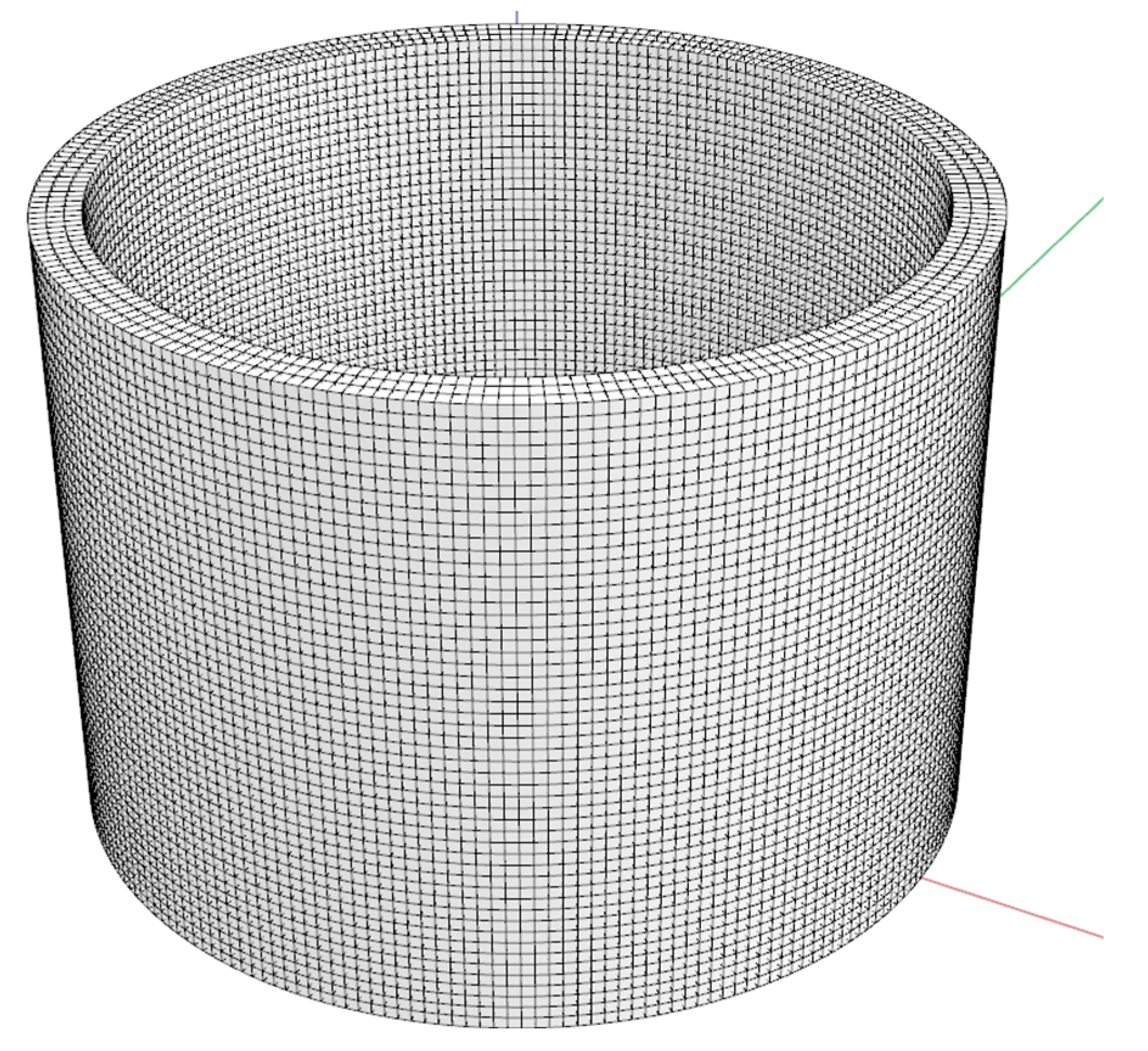
| Geometry Parameter | Hollow Cylinder |
|---|---|
| Geometry height [mm] | 500 |
| Maximum overhang [°] | 0 |
| Perimeter length [mm] | 2199 |
| Perimeter length variability [-] | COV * = 0 |
| Perimetric complexity [-] | 1 ** |
| Geometry volume [m3] | 0.0440/0.0659 |
| Bounding box ratio [-] | 0.66 |
| Minimal horizontal radius [mm] | R > 0 *** R = 0 **** |
| Input Settings | Remark | |
|---|---|---|
| Element length [mm] | 10 | |
| Elements in width | 3 | |
| Elements in height | 2 | |
| Number of segments | 8 | S8 |
| Extended settings | ||
| Bead width factor | - | |
| Interaction type | Contact-based | - |
| Element type | 8-node linear brick | C3D8 |
| Processor CPUs | 8 | - |
| Numerical stabilization | OFF | - |
| No. | [mm/s] | [mm] | ||
|---|---|---|---|---|
| 1 | 60 | 40 | 20 | 191.043 |
| 2 | 180 | 40 | 20 | 189.835 |
| 3 | 60 | 60 | 20 | 283.219 |
| 4 | 180 | 60 | 20 | 264.265 |
| 5 | 60 | 50 | 10 | 285.645 |
| 6 | 180 | 50 | 10 | 244.727 |
| 7 | 60 | 50 | 30 | 285.557 |
| 8 | 180 | 50 | 30 | 285.506 |
| 9 | 120 | 40 | 10 | 257.226 |
| 10 | 120 | 60 | 10 | 350.549 |
| 11 | 120 | 40 | 30 | 229.959 |
| 12 | 120 | 60 | 30 | 253.671 |
| 13 * | 120 | 50 | 20 | 285.032 |
| Term | p-Value | VIF | |||
|---|---|---|---|---|---|
| Constant | 285.0 | 35.4 | 8.05 | 0.004 | - |
| −7.6 | 12.5 | −0.61 | 0.585 | 1.00 | |
| 35.5 | 12.5 | 2.83 | 0.066 | 1.00 | |
| −10.4 | 12.5 | −0.83 | 0.466 | 1.00 | |
| ∗ | −25.2 | 23.4 | −1.08 | 0.360 | 1.35 |
| −27.7 | 23.4 | −1.18 | 0.322 | 1.35 | |
| 15.5 | 23.4 | 0.66 | 0.554 | 1.35 | |
| −4.4 | 17.7 | −0.25 | 0.818 | 1.00 | |
| 10.2 | 17.7 | 0.58 | 0.604 | 1.00 | |
| −17.4 | 17.7 | −0.98 | 0.398 | 1.00 |
Disclaimer/Publisher’s Note: The statements, opinions and data contained in all publications are solely those of the individual author(s) and contributor(s) and not of MDPI and/or the editor(s). MDPI and/or the editor(s) disclaim responsibility for any injury to people or property resulting from any ideas, methods, instructions or products referred to in the content. |
© 2023 by the authors. Licensee MDPI, Basel, Switzerland. This article is an open access article distributed under the terms and conditions of the Creative Commons Attribution (CC BY) license (https://creativecommons.org/licenses/by/4.0/).
Share and Cite
Vespalec, A.; Podroužek, J.; Koutný, D. DoE Approach to Setting Input Parameters for Digital 3D Printing of Concrete for Coarse Aggregates up to 8 mm. Materials 2023, 16, 3418. https://doi.org/10.3390/ma16093418
Vespalec A, Podroužek J, Koutný D. DoE Approach to Setting Input Parameters for Digital 3D Printing of Concrete for Coarse Aggregates up to 8 mm. Materials. 2023; 16(9):3418. https://doi.org/10.3390/ma16093418
Chicago/Turabian StyleVespalec, Arnošt, Jan Podroužek, and Daniel Koutný. 2023. "DoE Approach to Setting Input Parameters for Digital 3D Printing of Concrete for Coarse Aggregates up to 8 mm" Materials 16, no. 9: 3418. https://doi.org/10.3390/ma16093418
APA StyleVespalec, A., Podroužek, J., & Koutný, D. (2023). DoE Approach to Setting Input Parameters for Digital 3D Printing of Concrete for Coarse Aggregates up to 8 mm. Materials, 16(9), 3418. https://doi.org/10.3390/ma16093418