

Shear Behavior of Reinforced Concrete Beam Retrofitted with Modularized Steel Plates


Abstract
:1. Introduction
- (1)
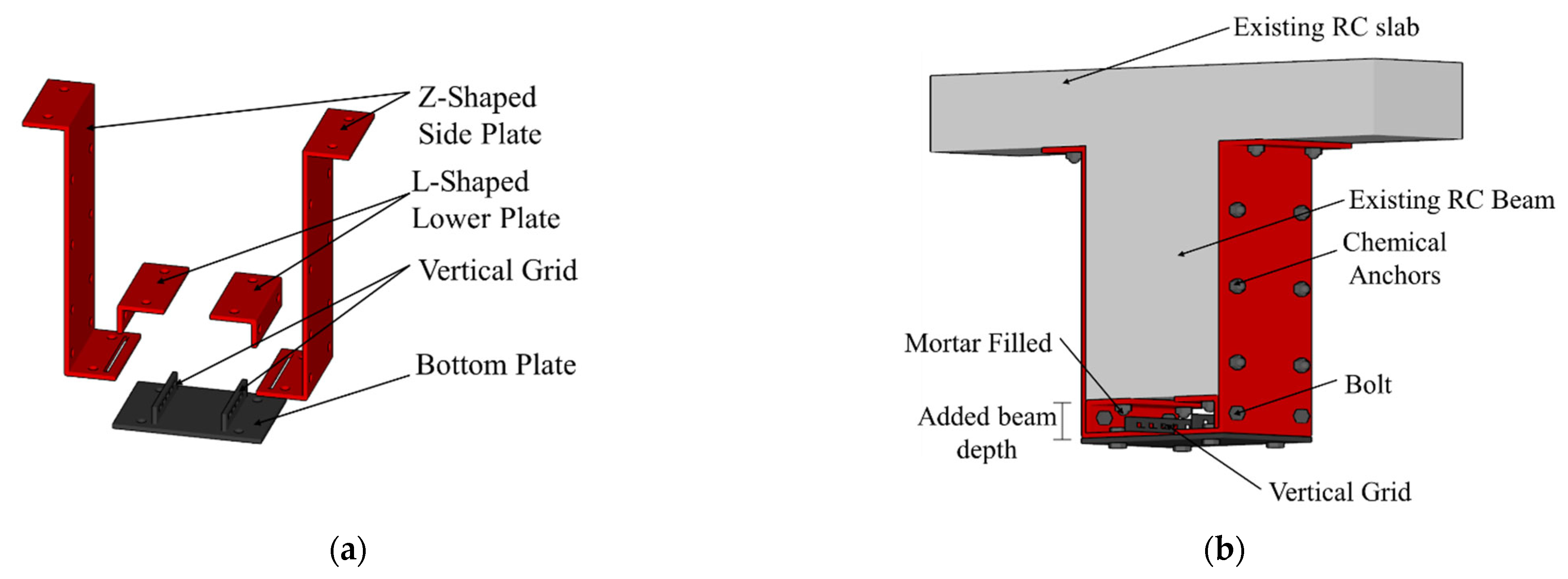
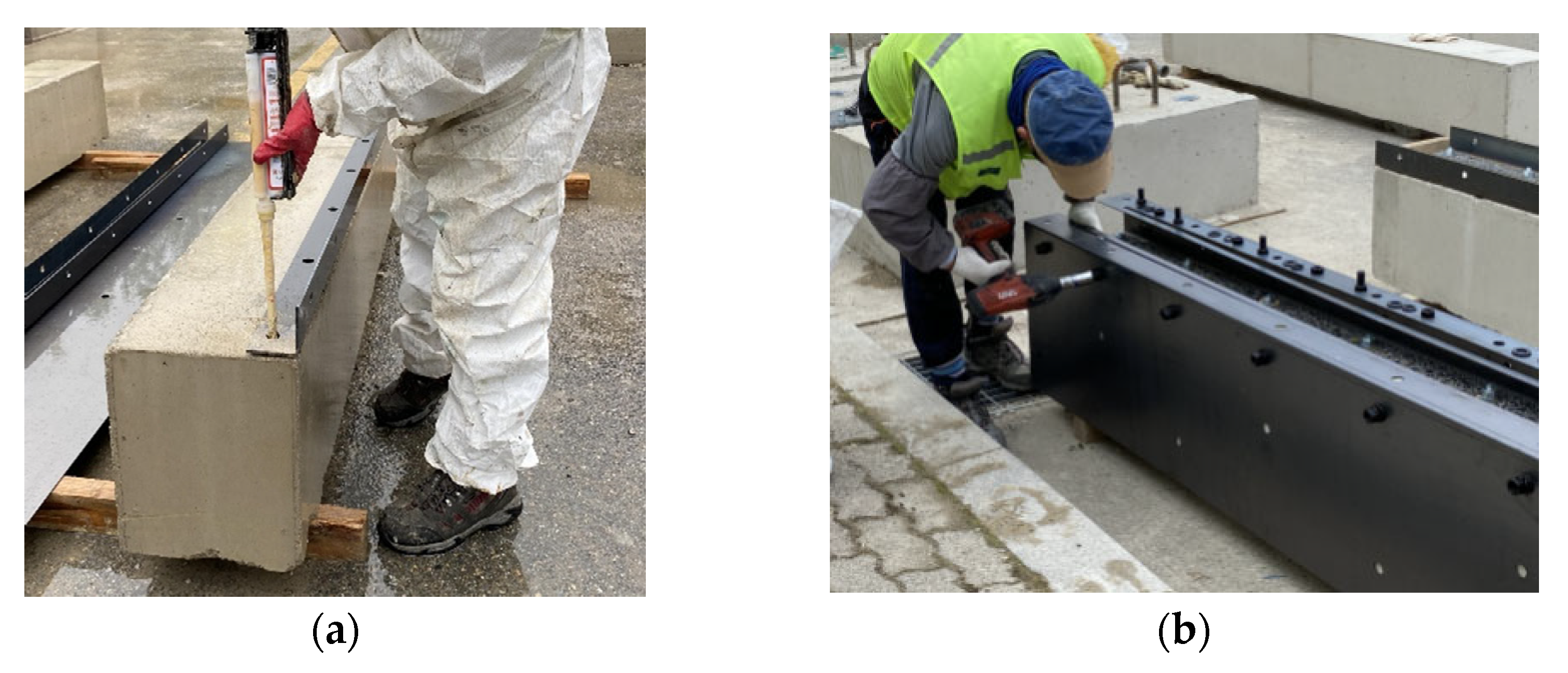
- The L-shaped lower plates are fixed to the bottom of the concrete specimen, using a chemical anchor.
- (2)
- The Z-shaped side plates are bolted to the L-shaped lower plates and then bonded to the side of the beam with a chemical anchor.
- (3)
- The bottom plate is inserted into the slot of the Z-shaped side plates to tighten the bottom plate and bond with bolts.
- (4)
- After integrating the side plates with chemical anchors, mortar is injected between L-shaped lower plates and the bottom plate, while the specimen is upside down to prevent filling defects in the mortar.
2. Experimental Program
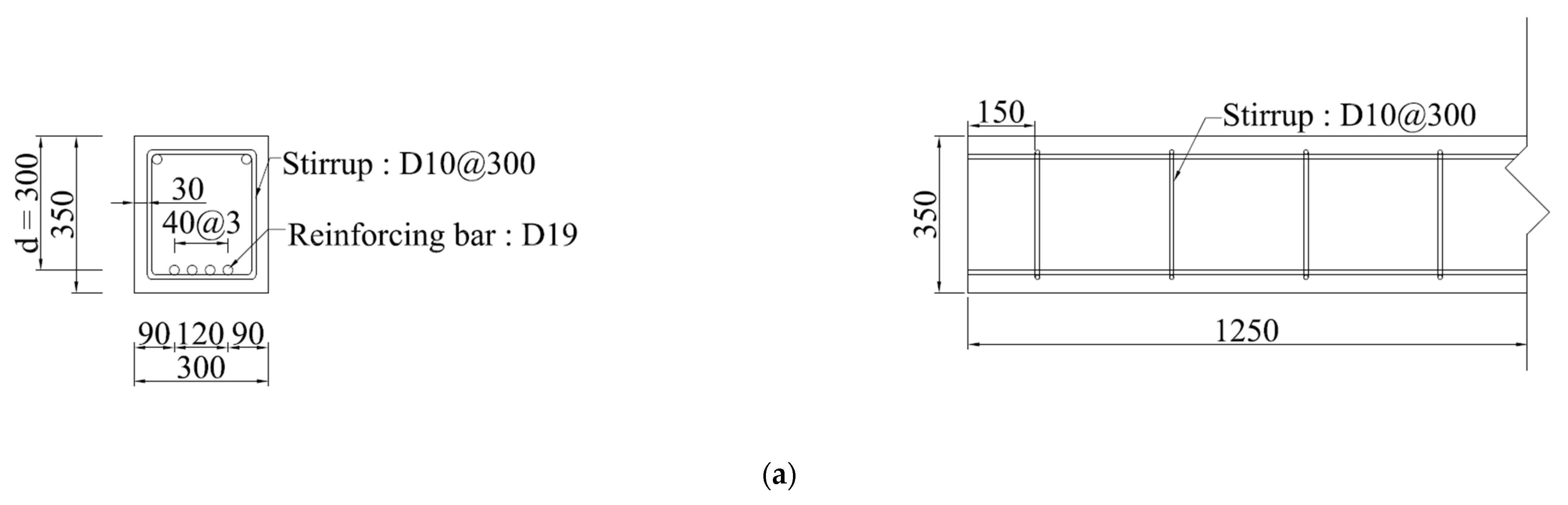
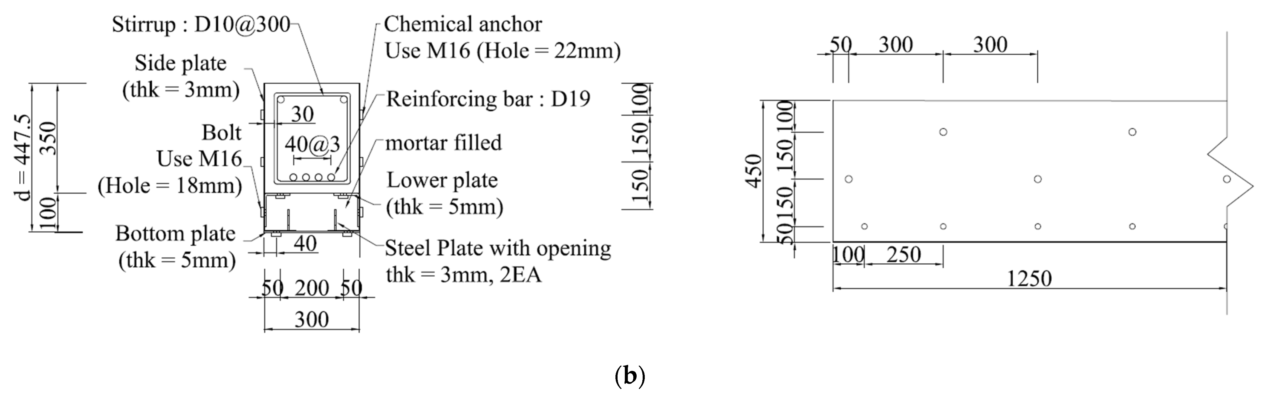
2.1. Specimen Details
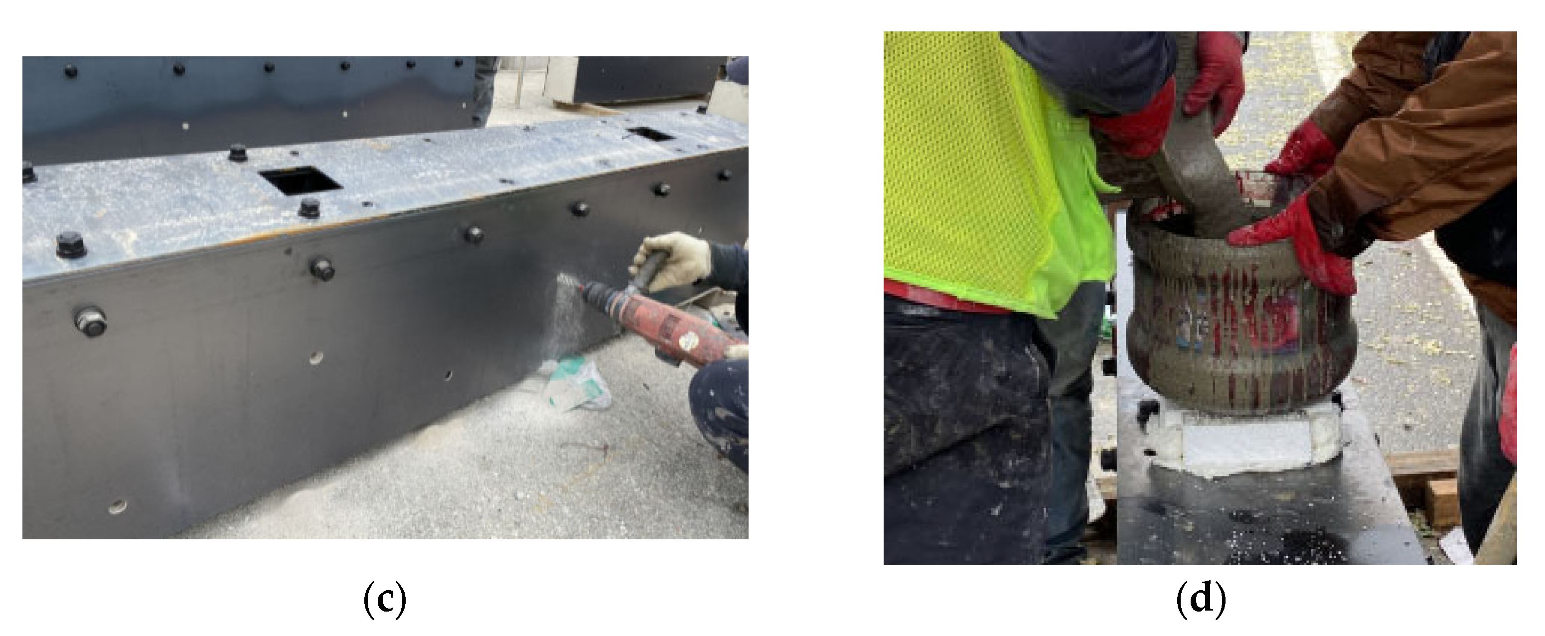
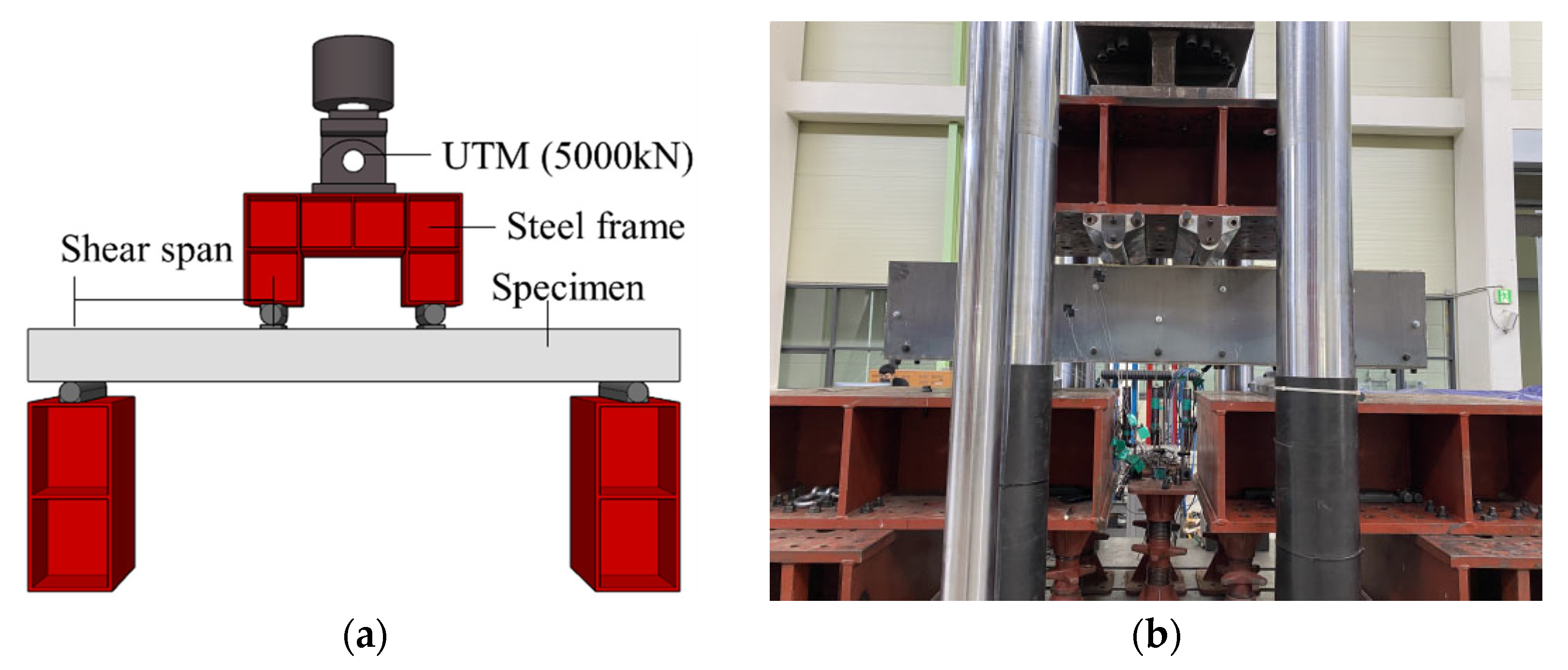
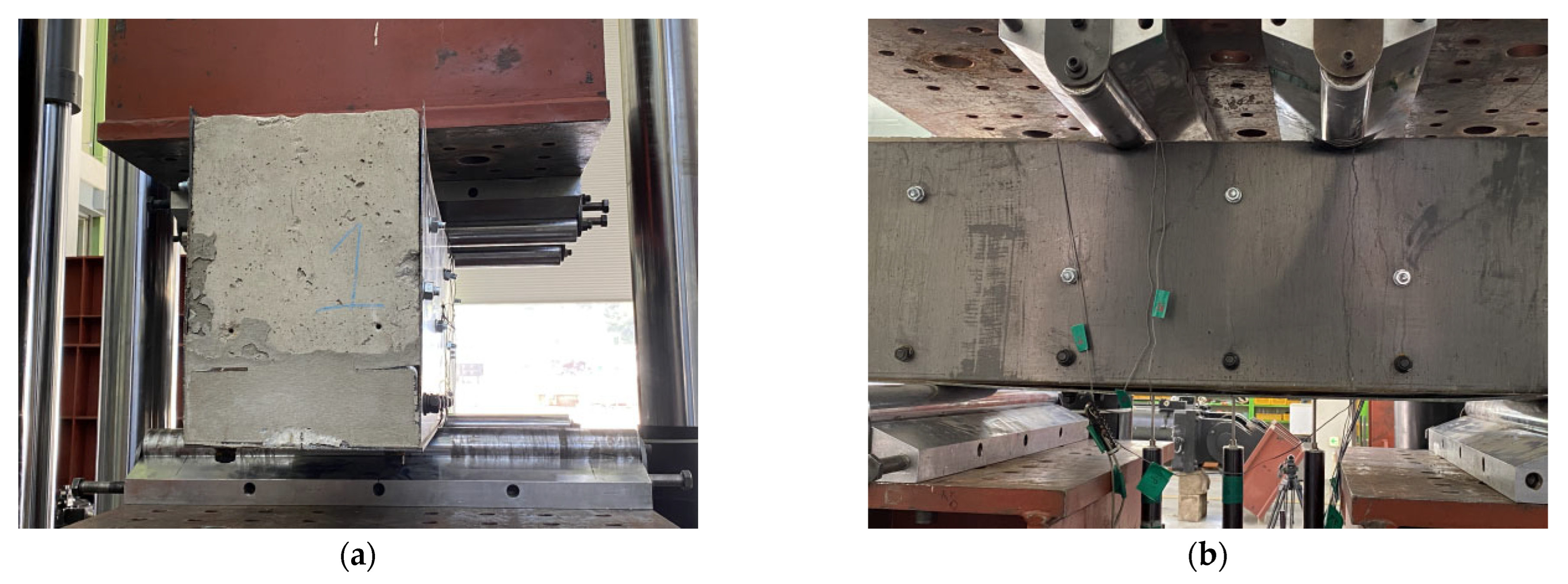
2.2. Test Set Up
3. Test Results and Discussion
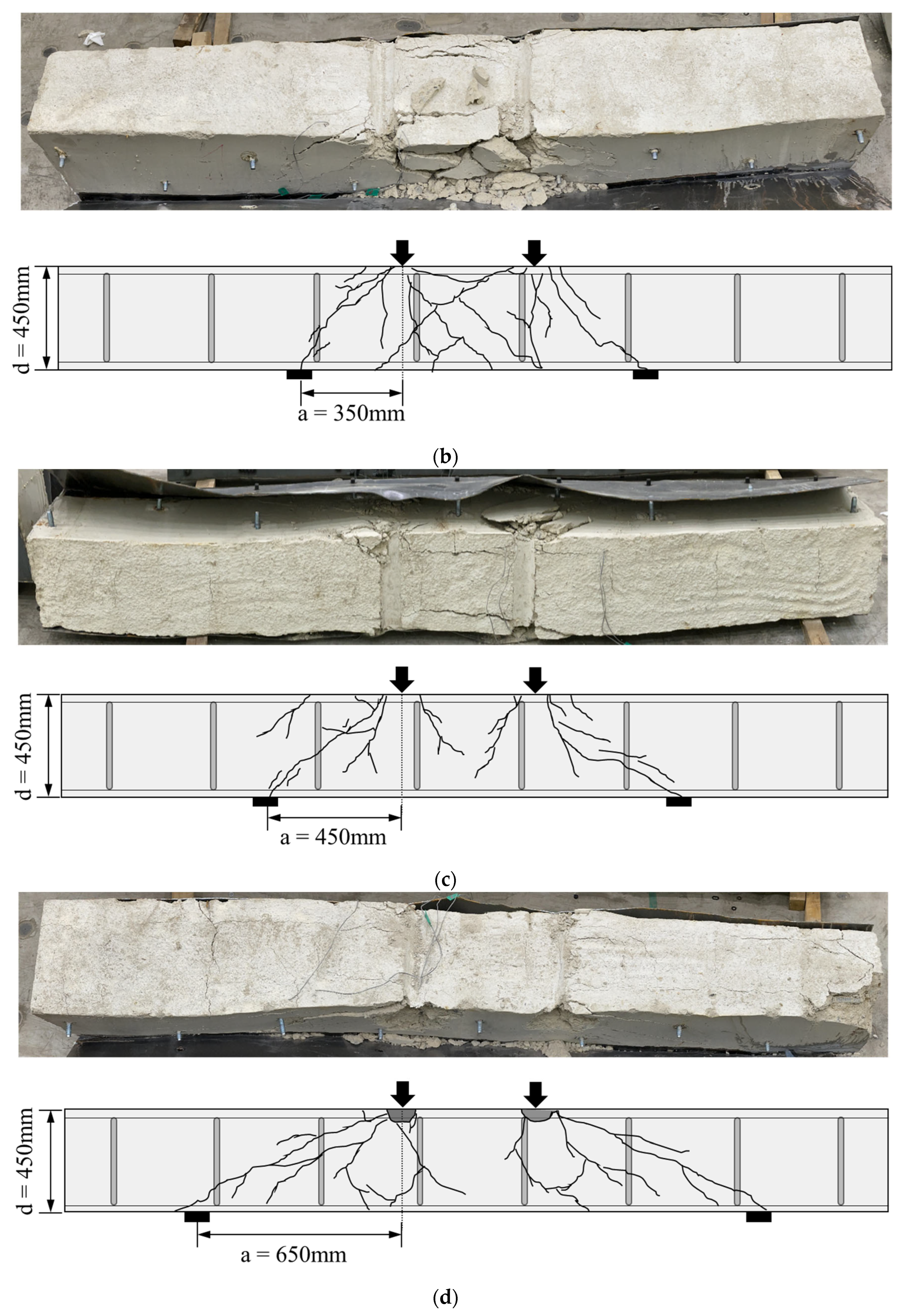
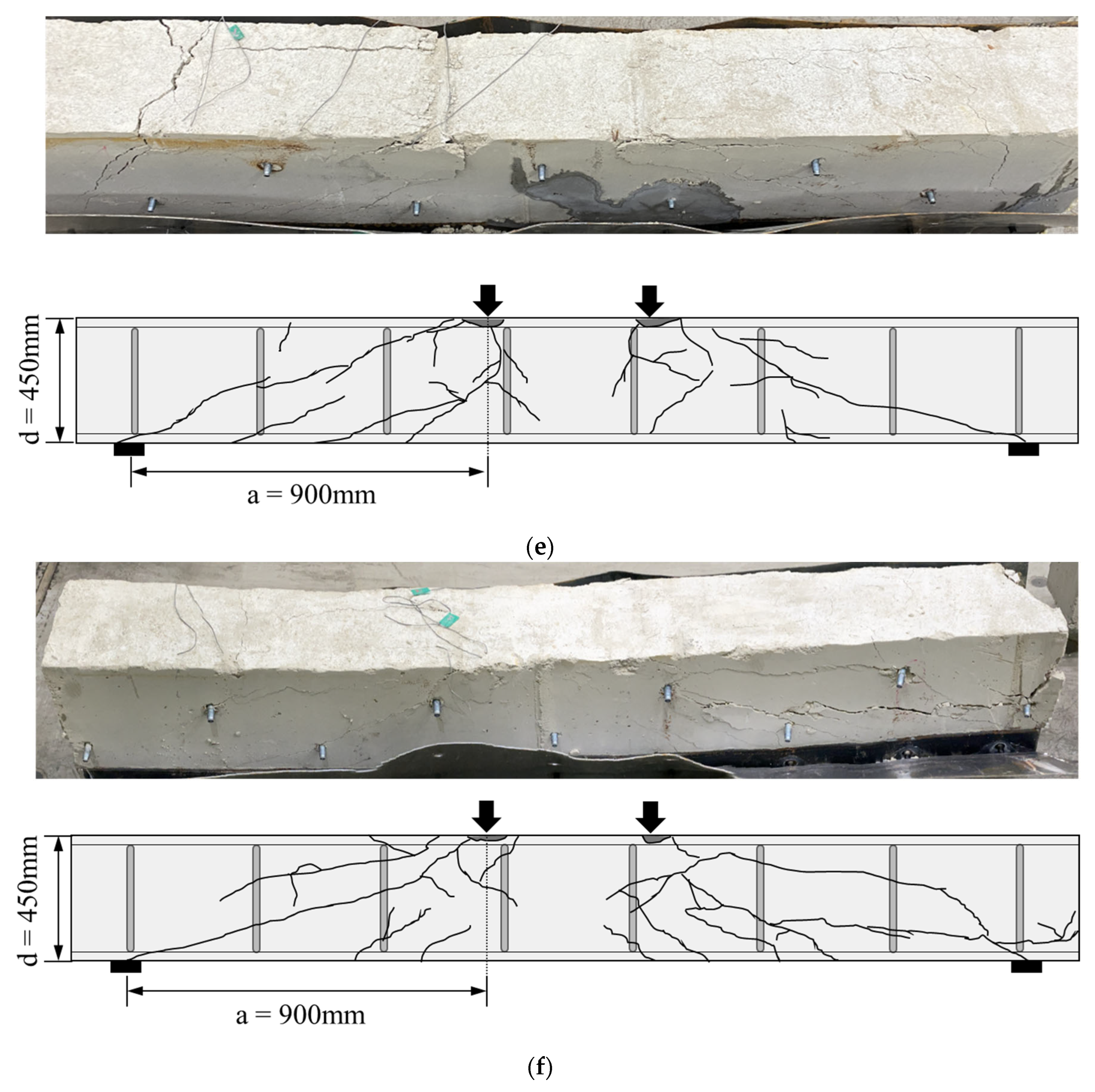
3.1. Crack Propagation and Failure Mode
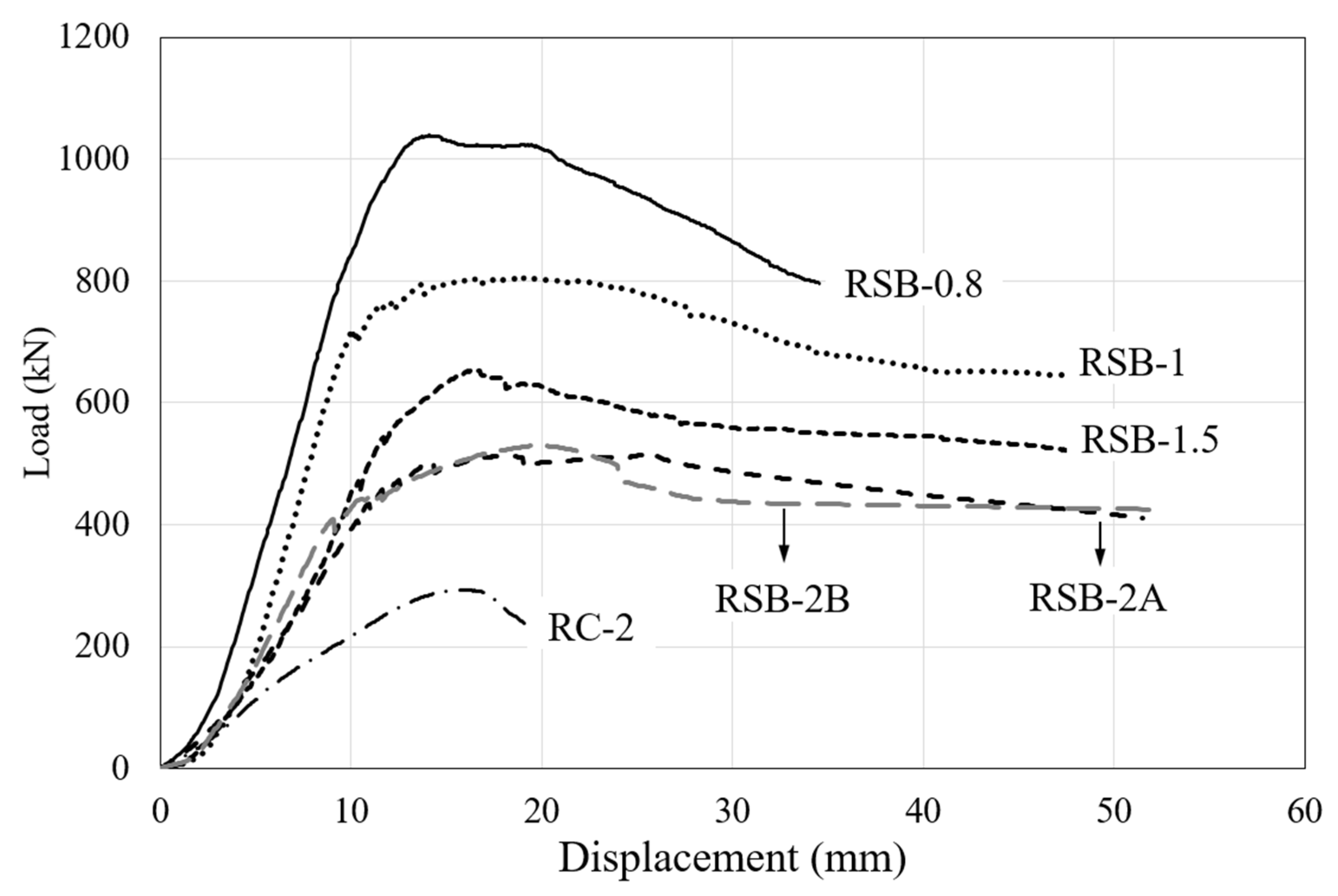
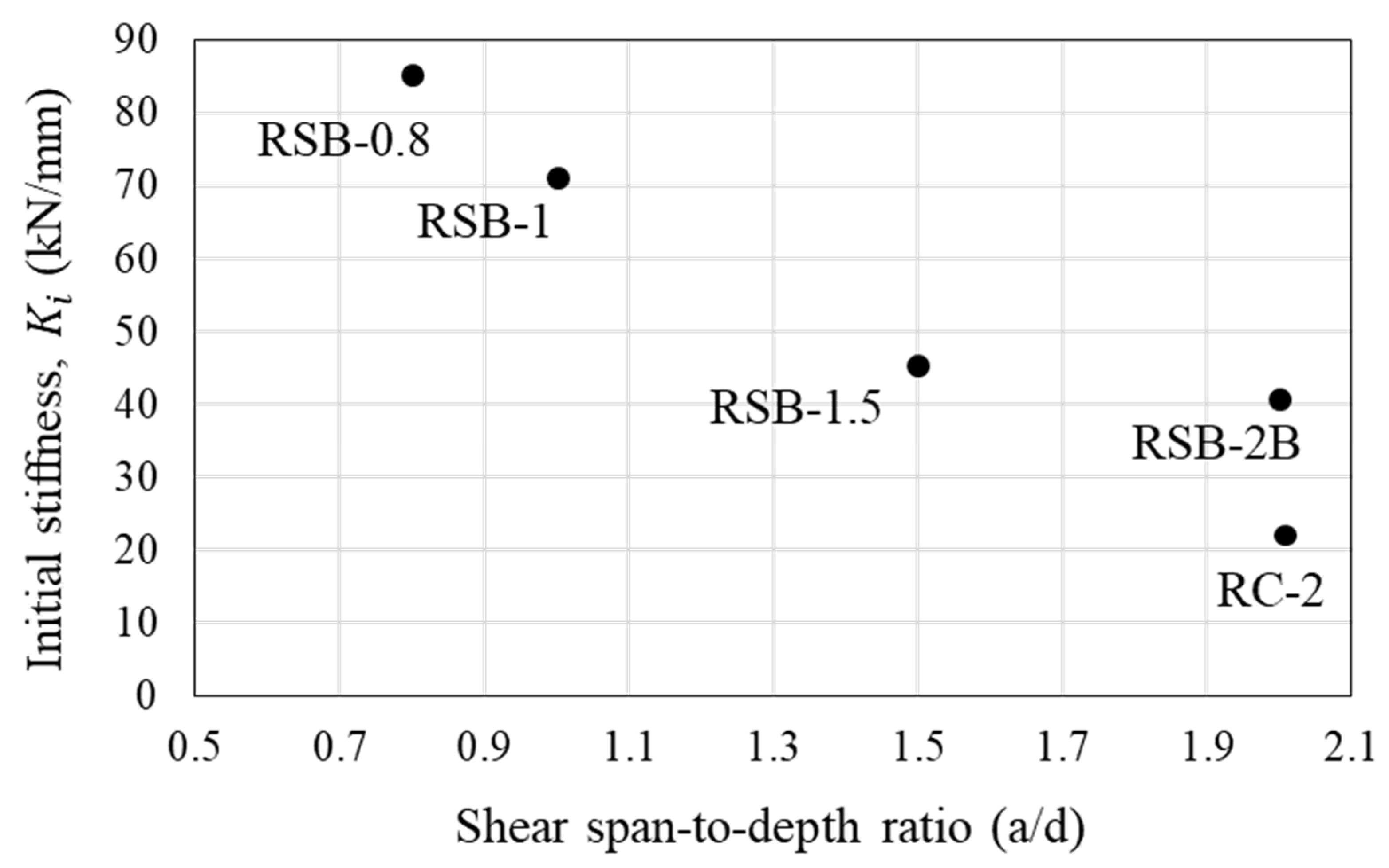
3.2. Load-Deflection Relationship
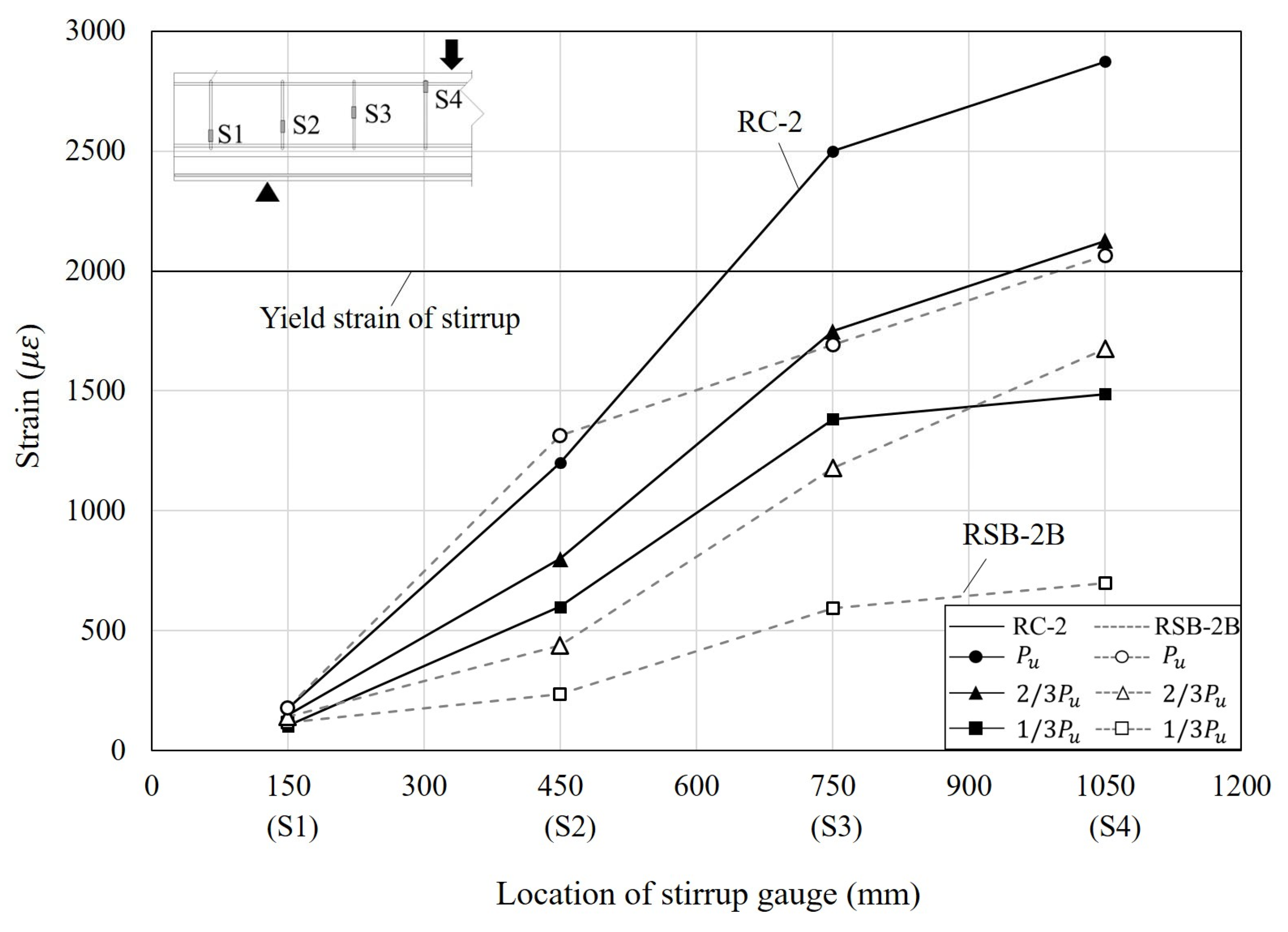
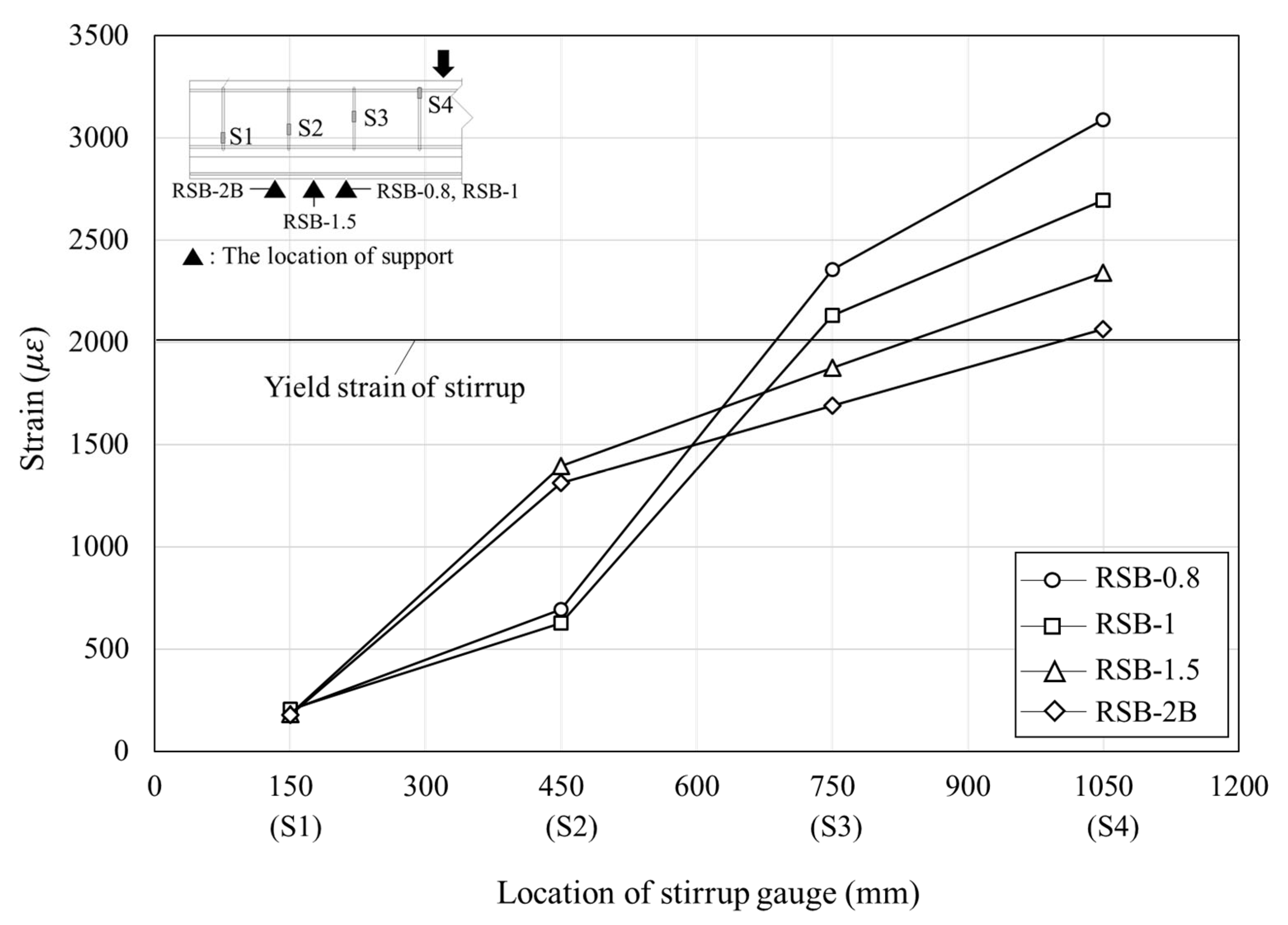
3.3. Load–Strain Relationship
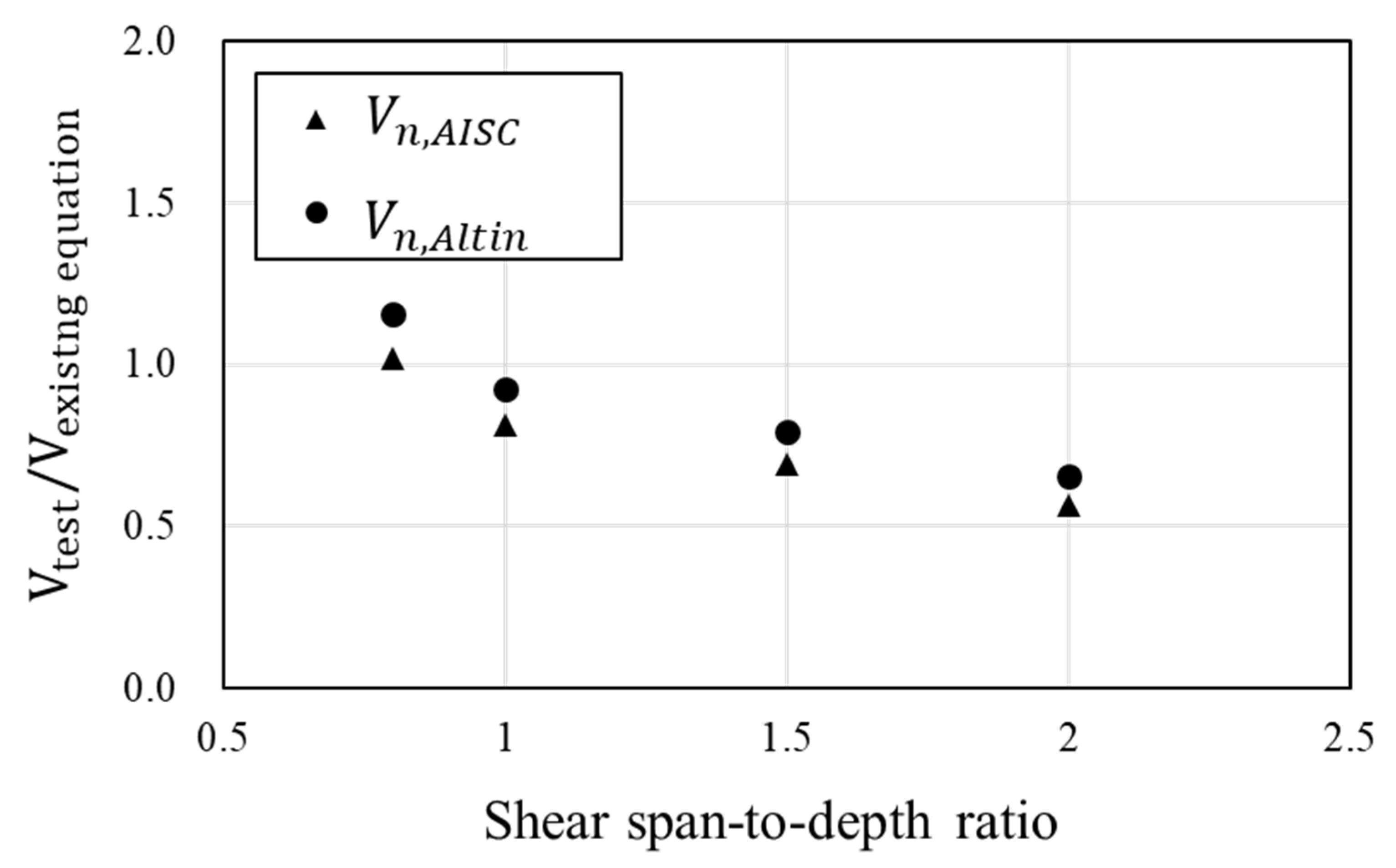
3.4. Prediction of Shear Strength
4. Conclusions
- (1)
- Typical shear dominant cracks and failure modes were observed in all specimens. The failure of the retrofitted beam in shear is characterized by a gradual and ductile behavior in contrast to the typical brittle failure of RC beams in shear. This means that the modularized steel plates contribute to the ductile behavior. At the end of the experiment, local buckling did not occur at the side plates and bottom plate, and the joint between the existing RC beam and side steel plate was not detached. Therefore, the spacing and bonding method of anchor bolts ensures the attachment of the concrete beam and the steel plates.
- (2)
- It was confirmed that the maximum load of RSB-2B was 529.25 kN, 1.8 times the maximum load of RC-2. In addition, the initial stiffness of RSB-2B was 1.9 times that of RC-2, and it was also confirmed that the retrofit method with modularized steel plates improves the stiffness of the RC beams. Therefore, the retrofitting method in this study is considered to effectively improve the shear performance of RC beams. As the shear span-to-depth ratio decreased, the maximum load increased, and then after reaching the maximum load, it gradually failed. The steel plates improve the shear strength and contribute to preventing brittle failure.
- (3)
- This study evaluated whether the shear strength of RC beams retrofitted by modularized steel plates can be predicted by the existing shear strength equations including the AISC 360-16 and ACI 318-19 provisions and the proposed equation by the other researchers. As the comparison of the experimental results with the existing shear strength equations shows, they overestimated the experimental shear strength with a large shear span-to-depth ratio. This is due to the assumption that the steel plates installed throughout the beams contributed equally to the shear resistance. It is recommended that the existing shear strength equations be modified to account for the actual contribution of the steel plates to the shear resistance within the shear span.
Author Contributions
Funding
Institutional Review Board Statement
Informed Consent Statement
Data Availability Statement
Acknowledgments
Conflicts of Interest
References
- Sezen, H.; Miller, E.A. Experimental evaluation of axial behavior of strengthened circular reinforced-concrete columns. J. Bridge Eng. 2011, 16, 238–247. [Google Scholar] [CrossRef]
- Truong, G.T.; Kim, J.C.; Choi, K.K. Seismic performance of reinforced concrete columns retrofitted by various methods. Eng. Struct. 2017, 134, 217–235. [Google Scholar] [CrossRef]
- Chen, X.; Ding, M.; Zhang, X.; Liu, Z.; Ma, H. Experimental investigation on seismic retrofit of gravity railway bridge pier with CFRP and steel materials. Constr. Build. Mater. 2018, 182, 371–384. [Google Scholar] [CrossRef]
- Raoof, S.M.; Koutas, L.N.; Bournas, D.A. Textile-reinforced mortar (TRM) versus fibre-reinforced polymers (FRP) in flexural strengthening of RC beams. Constr. Build. Mater. 2017, 151, 279–291. [Google Scholar] [CrossRef]
- Zhang, Y.; Xie, J.; Wang, L. Experimental study on RC T-section beams strengthened with bottom steel plates. Jordan J. Civ. Eng. 2018, 12, 502–515. [Google Scholar]
- Razaqpur, A.G.; Lamberti, M.; Ascione, F. Debonding evolution in nonlinear FRP-retrofitted RC beams with cohesive interface. Compos. Struct. 2020, 236, 111858. [Google Scholar] [CrossRef]
- Chen, C.; Yang, Y.; Yu, J.; Yu, J.; Tan, H.; Sui, L.; Zhou, Y. Eco-friendly and mechanically reliable alternative to synthetic FRP in externally bonded strengthening of RC beams: Natural FRP. Compos. Struct. 2020, 241, 112081. [Google Scholar] [CrossRef]
- Esmaeili, J.; Aghdam, O.R.; Andalibi, K.; Kasaei, J.; Gencel, O. Experimental and numerical investigations on a novel plate anchorage system to solve FRP debonding problem in the strengthened RC beams. J. Build. Eng. 2022, 45, 103413. [Google Scholar] [CrossRef]
- Altin, S.; Anil, Ö.; Kara, M.E. Improving shear capacity of existing RC beams using external bonding of steel plates. Eng. Struct. 2005, 27, 781–791. [Google Scholar] [CrossRef]
- Keo, P.; Lepourry, C.; Somja, H.; Palas, F. Behavior of a new shear connector for U-shaped steel-concrete hybrid beams. J. Constr. Steel Res. 2018, 145, 153–166. [Google Scholar] [CrossRef]
- Chen, L.H.; Li, S.T.; Zhang, H.Y.; Wu, X.F. Experimental study on mechanical performance of checkered steel-encased concrete composite beam. J. Constr. Steel Res. 2018, 143, 223–232. [Google Scholar] [CrossRef]
- Chen, C.; Cheng, L.; Sui, L.; Xing, F.; Li, D.; Zhou, Y. Design method of end anchored FRP strengthened concrete structures. Eng. Struct. 2018, 176, 143–158. [Google Scholar] [CrossRef]
- Attari, N.; Youcef, Y.S.; Amziane, S. Seismic performance of reinforced concrete beam–column joint strengthening by FRP sheets. Structures 2019, 20, 353–364. [Google Scholar] [CrossRef]
- Luder, D.; Ariely, S.; Yalin, M. Stress corrosion cracking and brittle failure in a fiber-reinforced plastic (FRP) insulator from a 400 kV transmission line in humid environment. Eng. Fail. Anal. 2019, 95, 206–213. [Google Scholar] [CrossRef]
- Zhou, Y.; Chen, X.; Wang, X.; Sui, L.; Huang, X.; Guo, M.; Hu, B. Seismic performance of large rupture strain FRP retrofitted RC columns with corroded steel reinforcement. Eng. Struct. 2020, 216, 110744. [Google Scholar] [CrossRef]
- Kim, M.S.; Lee, Y.H. Flexural Behavior of Reinforced Concrete Beams Retrofitted with Modularized Steel Plates. Appl. Sci. 2021, 11, 2348. [Google Scholar] [CrossRef]
- Zsutty, T.C. Beam shear strength prediction by analysis of existing data. ACI Struct. J. 1968, 65, 942–951. [Google Scholar]
- ACI Committee 318. Building Code Requirements for Reinforced Concrete and Commentary (ACI 318-19); American Concrete Institute: Farmington Hills, MI, USA, 2019. [Google Scholar]
- American Institution of Steel Construction. AISC 2016: Specification for Structural Steel Buildings, 15th ed.; American Institution of Steel Construction: Chicago, IL, USA, 2016. [Google Scholar]


| No. | Name | Retrofit Method | Added Beam Depth (mm) | Shear Span-to-Depth Ratio (a/d) |
|---|---|---|---|---|
| 1 | RC-2 | None | None | 2 |
| 2 | RSB-0.8 | Modularized steel plates | 100 | 0.8 |
| 3 | RSB-1 | 100 | 1 | |
| 4 | RSB-1.5 | 100 | 1.5 | |
| 5 | RSB-2A | 100 | 2 | |
| 6 | RSB-2B | 100 | 2 |
| Material | Compressive Strength (MPa) | Yield Strength (MPa) | Tensile Strength (MPa) | Modulus of Elasticity (MPa) |
|---|---|---|---|---|
| Concrete | 23.2 | - | - | 25,563 |
| Rebar, stirrup | - | 402.8 | - | 200,000 |
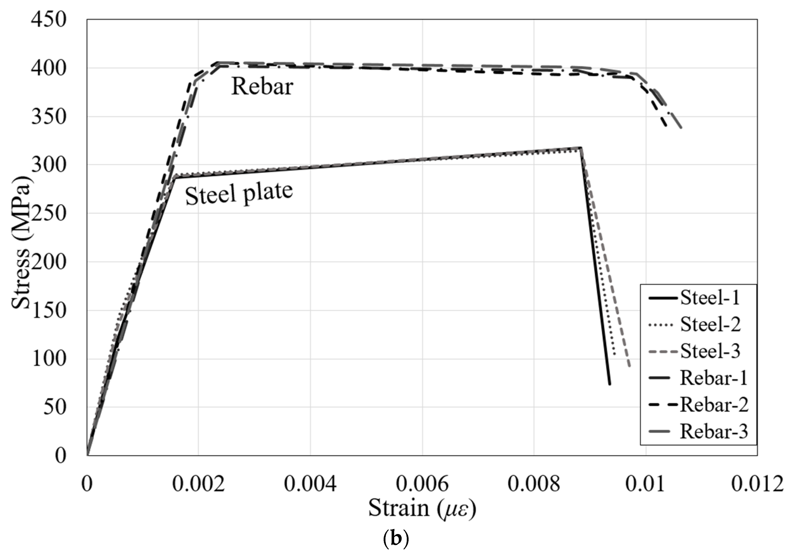
| Steel plate | - | 275.5 | 316.4 | 205,000 |
| No. | Name | (kN) | (kN) | (mm) | (mm) | (kN/mm) |
|---|---|---|---|---|---|---|
| 1 | RC-2 | 293.40 | 234.90 | 15.41 | 19.35 | 22.16 |
| 2 | RSB-0.8 | 1038.95 | 831.45 | 14.08 | 31.93 | 85.23 |
| 3 | RSB-1 | 805.40 | 644.30 | 18.99 | 47.57 | 71.29 |
| 4 | RSB-1.5 | 654.10 | 523.20 | 16.83 | 47.19 | 45.34 |
| 5 | RSB-2A | 515.11 | 414.90 | 18.13 | 51.51 | 40.67 |
| 6 | RSB-2B | 529.25 | 423.40 | 19.56 | 52.30 | 42.10 |
| No. | Specimens | Test | Existing Shear Strength Equation | |
|---|---|---|---|---|
| (kN) | (kN) | (kN) | ||
| 1 | RSB-0.8 | 519.48 | 510.1 | 449.4 |
| 2 | RSB-1 | 402.70 | 495.8 | 435.0 |
| 3 | RSB-1.5 | 327.05 | 472.3 | 411.5 |
| 4 | RSB-2A | 259.33 | 457.4 | 396.6 |
Disclaimer/Publisher’s Note: The statements, opinions and data contained in all publications are solely those of the individual author(s) and contributor(s) and not of MDPI and/or the editor(s). MDPI and/or the editor(s) disclaim responsibility for any injury to people or property resulting from any ideas, methods, instructions or products referred to in the content. |
© 2023 by the authors. Licensee MDPI, Basel, Switzerland. This article is an open access article distributed under the terms and conditions of the Creative Commons Attribution (CC BY) license (https://creativecommons.org/licenses/by/4.0/).
Share and Cite
Kim, M.S.; Lee, Y.H. Shear Behavior of Reinforced Concrete Beam Retrofitted with Modularized Steel Plates. Materials 2023, 16, 3419. https://doi.org/10.3390/ma16093419
Kim MS, Lee YH. Shear Behavior of Reinforced Concrete Beam Retrofitted with Modularized Steel Plates. Materials. 2023; 16(9):3419. https://doi.org/10.3390/ma16093419
Chicago/Turabian StyleKim, Min Sook, and Young Hak Lee. 2023. "Shear Behavior of Reinforced Concrete Beam Retrofitted with Modularized Steel Plates" Materials 16, no. 9: 3419. https://doi.org/10.3390/ma16093419
APA StyleKim, M. S., & Lee, Y. H. (2023). Shear Behavior of Reinforced Concrete Beam Retrofitted with Modularized Steel Plates. Materials, 16(9), 3419. https://doi.org/10.3390/ma16093419