Abstract
TiO2 is one of the most investigated materials due to its abundance, lack of toxicity, high faradaic capacitance, and high chemical and physical stability; however, its potential use in energy storage devices is constrained by its high internal resistance and weak van der Waals interaction between the particles. Carbon nanotubes are especially well suited for solving these issues due to their strong mechanical strength, superior electrical conductivity, high electron mobilities, excellent chemical and thermal stability, and enormous specific nanoporous surface. The hydrothermal approach was followed by chemical vapor deposition to produce a network composite of titanium dioxide nanoribbons (TNRs) and multi-walled carbon nanotubes (MWCNTs). The nanocomposite was characterized using a variety of methods. One phase of TiO2-B nanoribbons has porous pits on its surface, and MWCNTs are grown in these pits to produce a network-like structure in the nanocomposite. With a two-electrode supercapacitor configuration, the TNR/CNT gave a gravimetric capacitance of 33.33 F g−1, which was enhanced to 68.18 F g−1 in a redox-active electrolyte containing hydroquinone (HQ). Additionally, the areal capacitance per footprint was increased from 80 mF cm−2 in H2SO4 to 163.63 mF cm−2 in H2SO4/HQ. The TNR/CNT supercapacitor has superior cyclic stability than the previously reported TiO2-based electrodes, with 97.5% capacitance retention after 5000 cycles. Based on these results, it looks like the TNR/CNT supercapacitor could provide portable electronic power supplies with new ways to work in the future.
1. Introduction
Portable smart devices could benefit from supercapacitors because of their fast discharge speed, long cycle life, and high-power density, among other advantages. In terms of energy storage, supercapacitors are divided into electrochemical double-layer capacitors with higher power density linked to the electrode surface area and pseudocapacitors with higher energy density linked to faradaic redox [1]. High-performance electrode materials for supercapacitors have mostly been developed by modifying and blending pseudocapacitive materials such as transition metal oxides and conductive polymers with carbonaceous materials from double-layer capacitors [2,3]. As electrodes for supercapacitors, carbon nanotube electrodes have proven to retain the remarkable qualities of individual carbon nanotubes while also exhibiting good mechanical properties and structural stability [4,5]. This study also examined the properties of titanium dioxide (TiO2), which has a high faradaic capacitance and is chemically and physically stable [6]. Despite this, TiO2’s high internal resistance prevents it from being used in an energy storage device. Due to the weak van der Waals interaction between the particles, TiO2 has not yet been successfully used as an electrode in a supercapacitor, but it can be combined with other materials, particularly carbon-based materials. As shown in Table 1, previous studies on TiO2/activated carbon, TiO2/carbon nanotubes, and reduced graphene oxide/TiO2 nanobelt composites revealed that the combination of conductive nanocarbon and TiO2 was an efficient solution [7,8,9,10,11,12,13,14,15]. Selvakumar and Bhat developed TiO2/activated carbon nanocomposite electrodes, which have a specific capacitance of 122 F/g at current densities of 2, 4, 6, and 7 mA/cm2 [7]. A PANI/TiO2/GO composite with high specific capacitance—1020 F/g at 2 mV/s and 430 F/g at 1 A/g—was made by Su et al. [8]. The rGO-TiO2 nanobelts and nanoparticles made by Xiang et al. had specific capacitances of 225 and 62.8 F/g, respectively. Ramadoss et al. produced an rGO/TiO2 NR/rGO electrode with 114.5 F/g at a scan rate of 5 mV/s that maintained more than 85% of its initial capacitance after 4000 cycles [10]. Ramadoss and Kim used a microwave-assisted technique to produce a graphene–TiO2 hybrid nanostructure with a specific capacitance of 165 F/g at a scan rate of 5 mV/s in a 1 M Na2SO4 solution and retention of 90% specific capacitance after 5000 cycles [11]. High specific and interfacial capacitances, of 329 F/g and 52 mF/cm2 at a scan rate of 5 mV/s were achieved by coating TiO2 nanodots on MWCNTs using a binder-free method developed by Sankapal et al. [12]. Using a sacrificial template technique, Ke et al. produced a 3D carbon/TiO2/rGO composite with a specific capacitance of 23.6 mF/cm2 [13]. In a 0.5 M H2SO4 electrolyte, the TiO2/CNT hybrid produced by Yan et al. using the sol–gel technique exhibits a specific supercapacitance of 145 F/g [14]. By co-electrochemically reducing functionalized MWCNTs and GO onto TiO2NTs/Ti, Faraji created a 3D R(fMWCNT-GO)/TiO2NTs/Ti electrode with a specific capacitance of 600 F/g at 12 A/g in 1 M H2SO4 and a long cycle life of 90% capacitance retention over 500 cycles [15]. Despite previous research, it is urgent to create TiO2/carbon-based nanocomposite electrodes for supercapacitors that are less expensive, have a high yield and surface area, and are more stable.

Table 1.
The CNTs and nanocomposite’s crystallite sizes (CS), d-spacing, dislocation densities, texture coefficients, and strain.
The hydrothermal approach was used in this study to achieve the controllability of TiO2 structures in a simple, low-cost method while also significantly increasing the energy storage capacity of the electrode materials. Metal carbides will be used more in energy storage devices as a result of this. The TiO2 nanoribbon acts as a substrate for the chemical vapor deposition (CVD) of carbon nanotubes on its surface. In various solutions, electrochemical impedance spectroscopy (EIS), cyclic voltammetry (CV), and galvanostatic charge/discharge (GCD) were used to measure the nanocomposite performance. Their capacity, specific power, and specific energy were also investigated to evaluate how well they will operate over 5000 cycles of reusability.
2. Experimental Section
2.1. Materials
Loba Chemie (Mumbia, India) provided the TiO2 powder (Loba Chemie, India, CAS No. 13463-67-7), Fe (NO3)3·9H2O (Loba Chemie, India, CAS No. 7782-61-8), Co(NO3)2·H2O (Loba Chemie, India, CAS No. 10026-22-9), and Al(NO3)3·9H2O (Loba Chemie, India, CAS No. 7784-27-2). Scharlab (Barcelona, Spain) supplied HCl (36.6%). SDFCL (Mumbia, India) supplied H2SO4 (98%) and HNO3 (69%). Deliveries from ADWIC (Cairo, Egypt) included commercial C2H4 gas, NH4OH (32%) and NaOH.
2.2. TNRs/CNTs Nanocomposite Fabrication
TNRs were made using an alkaline hydrothermal process. In 400 mL of 10 M NaOH, 4 gm of TiO2 powder was added and stirred for 30 min. In a 1 L autoclave, the resulting solution was poured. The autoclave was then placed in a 170 °C oven for 24 h. The result was then filtered before being washed with 0.1 M HCl and distilled water. Finally, the white powder was dried for 4 h at 80 °C and calcined for 2 h at 450 °C [16].
The TiO2 nanoribbons were mixed with Fe (NO3)3·9H2O, Co (NO3)2·6H2O, and Al (NO3)3·9H2O in 100 mL of distilled water under stirring, with mass ratios of 10 TiO2:20 Fe:20 Co:50 Al2O3. By slowly drizzling in drops of ammonia solution, the pH level rose to 8 and the precipitation occurred. The solution was filtered and rinsed with distilled water. The solution was aged for 2 h at room temperature. To eliminate excess nitrate, the product was first dried for 4 h at 80 °C and then calcined for 4 h at 450 °C [17].
The functionalized titanium nanoribbons were used as a catalyst for the formation of CNTs using tubular chemical vapor deposition (CVD). The carbon source was C2H4, and the carrier gas was N2. C2H4:N2 was a 1:10 v/v ratio. The CNTs were grown for 50 min at 700 °C [18]. For 6 h at 120 °C, we heated the CVD-prepared product in a round bottom flask to dilute it with H2SO4: HNO3 (1:3). Next, the powder was cleaned and dried at 80 °C for 4 h using distilled water [19,20]. A total of 1 g of the composite is expected to cost between $5 and $6.
2.3. Characterization of the Produced Nanomaterials
X-ray diffraction (XRD; PANalytical, Warsaw, Poland) using Cu K α radiation (=1.5406 Å) at 45 kV and 40 mA validated the crystal structure of the CNTs and TNRs/CNTs. A transmission electron microscope (TEM) was used to examine the morphologies of the produced nanocomposites (JEOL JEM-2100 TEM, Tokyo, Japan).
2.4. Supercapacitor Manufacturing Processes
A total of 20 mg of active material powder and 50 µL of Nafion were dispersed in 300 µL of ethanol and then blended into a slurry in a smaller agate mortar. To make a homogenous catalyst ink, the mixture was agitated for 12 h. On the Au electrode, two identical slurries of about 50 µL (3 mg) were placed (1 cm2). Two sheets of filter paper, on the other hand, were dipped in electrolytes, which may be either 1 M H2SO4 or a mixture of 1 M H2SO4 and 0.4 M hydroquinone (HQ) (H2SO4/HQ). After that, a sheet of filter paper was placed between the two electrodes as a separator.
2.5. Electrochemical Analysis
All electrochemical measurements in the two-electrode systems were performed using an electrochemical workstation (CHI 660E; CH Instruments, Austin, TX, USA). Cyclic voltammetry (CV), galvanostatic charge/discharge (GCD), and electrochemical impedance spectroscopy (EIS) were used to make the measurements. The CV experiments were carried out at various scan rates between 0 and 1 V, ranging from 5 to 100 mV s−1. The GCD measurements were carried out in a voltage window of 0 to 1 V at 0.2–1 A g−1. The EIS spectra were recorded at an open circuit potential of 5 mV AC voltage amplitude and frequencies ranging from 10 mHz to 100 kHz. The tests were all conducted at room temperature.
3. Results and Discussions
3.1. Characterization of the Produced Nanomaterials
3.1.1. Structural Properties
XRD spectroscopy was used to analyze the TNR/CNT nanocomposite and identify its crystal structure. The XRD charts for the nanocomposite CNTs and TNRs/CNTs are displayed in Figure 1. A strong peak associated with XRD diffraction from the (002) plane can be seen on the CNTs chart at 26.32°. In addition, the peaks at 42.91° and 44.94° are connected to the carbon’s in-plane (100) and (101) reflections, respectively, while the peak at 65.74° is connected to the XRD from (004) [21].
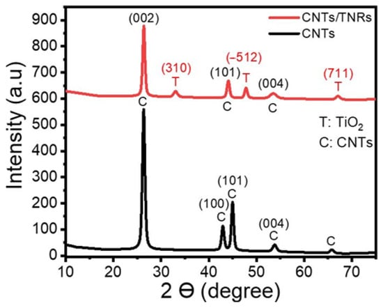
Figure 1.
The XRD pattern of a TNR/CNT nanocomposite.
The XRD pattern of TNRs/CNTs exhibited three unique CNT peaks at 2ϴ = 26.34°, 44.05°, and 53.48°, in the (002), (101), and (004) planes, respectively [17]. Additionally, TiO2-B is associated with the peaks in the Figure 1 planes (310), (−512), and (711) at 33.0°, 47.76°, and 67.02° [22,23,24].
The average crystallite size, CS, was determined using the Scherrer equation where is the full width at half maximum (FWHM); is the Bragg’s angle in radians; and λ is the X-ray wavelength (CuKα = 0.15405 nm) [25,26]. Additionally, the dislocation density (δ) was determined by applying Williamson and Smallman’s relation, where N = 1 represents the minimum dislocation density and δ = . Using Equation (1), the texture coefficient (TC) was also calculated from the data [25,26].
where N is the number of reflections and Ir = is the difference between the measured intensity I(hkl) and the standard intensity Io(hkl) for the plane hkl.
Table 1 contains the computed and actual values for the CNTs and the nanocomposite’s crystallite sizes (CS), d-spacing, dislocation densities, texture coefficients, and microstrain. Growing CNTs on the surface of TNRs resulted in an increase in the crystallite size of CNTs along (002) from 14.7 nm to 16.8 nm. TNRs typically have crystallite sizes between (−512) and (310) of 15.6 and 9.9 nm, respectively. Based on the values of the texture coefficient in Table 1, the preferred orientations for TiO2-B (TNRs) and CNTs were (−512) and (002), respectively. Additionally, the (−512) and (002) planes had lower TNR and CNT dislocation densities than the other planes. This is brought on by the grains along these planes having a higher crystallinity [27]. Table 1 reports the positive microstrain values, which indicate a lattice expansion and relaxation [28]. The CNTs in the pure sample and the composite are reported to have the highest values of microstrain along the (002).
3.1.2. Morphological Analysis
TEM was used to analyze the nanocomposite’s morphology. As illustrated in Figure 2a, the CVD-grown CNTs formed multi-walled carbon nanotubes (MWCNTs), with the inner and outer tubes having widths of 5 to 7 nm and 15 to 17 nm, respectively. TiO2 nanoribbons have a structure that is wider, longer, and straighter. The nanoribbons’ typical width ranged from 20 to 200 nm. As illustrated in Figure 2b, these nanoribbons have a dense distribution of nano pits on their surfaces. The nano pits have a diameter ranging from 4 to 8 nm [29]. As seen in the inset figure, the nanoribbon works as a substrate for the growth of carbon nanotubes on its surface.
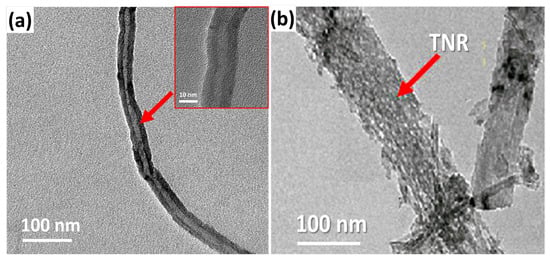
Figure 2.
TEM pictures of (a) the CNTs and the (b) TNR/CNT nanocomposite.
3.2. TNR/CNT Nanocomposite Electrochemical Performance in 1 M H2SO4
Any material’s capacitive behavior can be measured using cyclic voltammetry. CV was performed on a symmetric supercapacitor cell made in a sandwich-type geometry utilizing TNR/CNT electrodes, paper as a separator, and 1 M H2SO4 as an electrolyte to study the capacitive properties of TNR/CNTs, and the results were compared to those of CNTs. Figure 3a shows the cyclic voltammograms produced for TNRs/CNTs and CNTs at 10 mV s−1. Figure 3a shows the electrodes’ outstanding stability over the applied voltage range of 0 to 1 V. Using the formula [30], the specific capacitance was determined from the voltammograms.
where Cs is the specific capacitance found from the CV; ‘i’ is the average current found from the anodic and cathodic curves; gives the scan rate; and m is the weight of the active material in one electrode. The CNTs’ cyclic voltammograms are quasi-rectangular along the x-axis, with a small redox peak, in the beginning, showing that they have both double-layer and pseudocapacitance behavior. Because of the widespread oxidation of CNTs, oxidizable groups such as hydroxyl, carbonyl, and carboxyl are formed at defects in the nanotube carbon lattice, resulting in pseudocapacitance [30]. However, when TiO2 and the CNTs worked together, the TNR/CNTs showed an improved rectangular background and oxide peak.
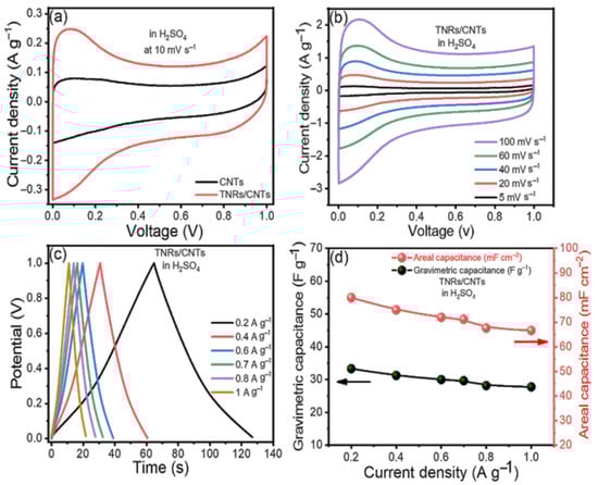
Figure 3.
The electrochemical performance of the TNR/CNT electrodes in the H2SO4 (a) cyclic voltammograms (CVs) of the CNTs and TNR/CNTs at a scan rate of 10 mV s−1, (b) CVs at different scan rates, (c) charge/discharge curves (CDs) at different current densities, and (d) computed gravimetric and areal capacitances at different current densities.
The TNR/CNTs performance was also assessed at various scan rates; Figure 3b shows the fluctuation of Cs with the scan rate. Because the redox reactions in TNR are dependent on the insertion–deinsertion of dopant ions from the electrolyte, the Cs values fall as the scan rate increases [31,32]. At low scan rates, ions from the electrolyte can move into almost all of the material’s pores. This causes a complete insertion reaction and the most capacitive behavior possible.
The CD curves of the TNR/CNT electrodes at different scan rates are shown in Figure 3c; the divergence from linearity is due to the pseudocapacitance from TNR. The longer charge and discharge times are due to the use of EDLC and faradic capacitance from TNRs and CNTs, respectively.
Figure 3d illustrates the supercapacitor’s gravimetric (Cwt) and areal (CA) capacitances at various current densities, as derived from the charge/discharge curves using the following equations [33,34].
where “I” represents the applied constant current (A); is the slope of the discharge curve; the two electrodes’ footprint area (cm2) is marked by A; and the total mass of the two electrodes is given by m (g).
At a current density of 0.2 A g−1, the gravimetric capacitance in H2SO4 reached its maximum value of 33.33 F g−1. As the current density decreased, the device’s area capacitance increased from 66.66 mF cm−2 to 80 mF cm−2. Choosing an electrolyte mixture improved the performance of our electrodes.
3.3. The TNR/CNTs Electrode’s Superior Performance
Hydroquinone (HQ) was added to 1 M H2SO4 to make a mixed electrolyte since it was believed to be an effective redox-active electrolyte that provided additional redox reactions [35]. Using a mixed electrolyte significantly enhanced the cyclic voltammetry integrated area (Figure 4a). In Figure 4b, the electrolyte had the longest CD duration, and the fact that it did not look like a triangle suggests that HQ is involved.
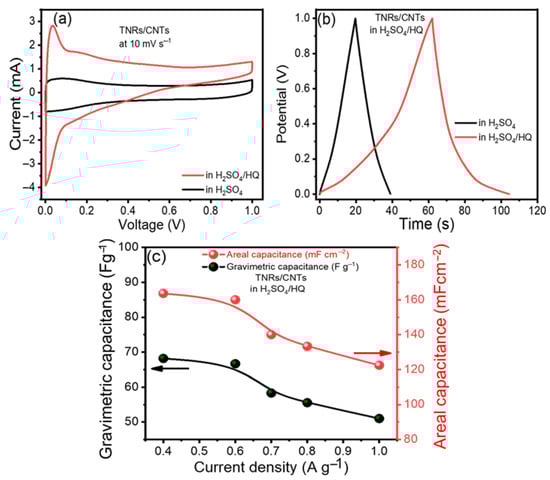
Figure 4.
Electrochemical performance improvement: (a) cyclic voltammograms (CVs) and (b) charge/discharge curves (CDs) of TNR/CNTs in H2SO4 and a mixed electrolyte, respectively, and (c) gravimetric and areal capacitances of the TNR/CNTs in the mixed electrolyte at different current densities.
In Figure 4c, the gravimetric and areal capacitances (Cwt and Cvol) of the TNR/CNT electrodes in the mixed electrolyte (H2SO4/HQ) at various current densities are displayed, with Cwt = 68.18 A g−1 demonstrating significantly superior performance than H2SO4, which was equal to 33.33 A g−1. Similarly, the areal capacitance per footprint of the device increased from 80 mF cm−2 in H2SO4 to 163.63 mF cm−2 in H2SO4/HQ. As a result, the development of supercapacitors with our composite TNR/CNT appears promising.
EIS measurements were taken at 100 kHz to 10 mHz, which is the frequency range. These EIS measurements aided in understanding the resistive components of the supercapacitors. In EIS, Nyquist plots are useful for determining the resistivity of the electrodes. In theory, Figure 5a is divided into two regions: a high-frequency 45-degree semicircular arc and a low-frequency straight line. The charge-transfer limiting process is represented by the high-frequency arc, in which the solution resistance (Rs) is connected in series with the double-layer capacitance (Cdl), which is connected in parallel with the charge-transfer resistance (Rct) and pseudocapacitance (Cp). The inset of Figure 5a shows the equivalent circuit provided with the values of their elements for TNR/CNTs in H2SO4/HQ. The resistance faced by the ions as they go through the separator toward the electrode surface is known as equivalent series resistance (ESR), and it may be measured at high frequency by the first intersection point on the x-axis [36]. Based on the experimental observations, as shown in the inset of Figure 5a, the ESR values for the material in H2SO4 and (HQ + H2SO4) were 0.54 Ω and 0.51 Ω, respectively. The second intersection point on the x-axis shows the charge-transfer resistance (Rct), which is based on the length of the semicircular arc and is equal to the overall resistance given by the electrode/electrolyte interfaces [37]. Furthermore, Rct is solely determined by the amount of active surface area on the electrode that the electrolyte can access. The length of the semicircle shown on the real axis can be used to determine Rct. Rct values for MWCNTs and TNR/CNTs were found to be 0.1 Ω and 0.06 Ω, respectively. Due to the redox behavior of the HQ, the TNRs/CNTs had a lower charge-transfer resistance, which was the same as a lower ion diffusion resistance and a higher capacitance.
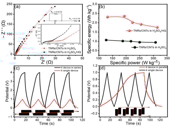
Figure 5.
(a) TNR/CNT Nyquist plots in H2SO4 and H2SO4/HQ, respectively. The inset shows enhanced Nyquist plots in the high-frequency area; (b) a Ragone plot of specific power vs. specific energy for TNR/CNTs in H2SO4 and H2SO4/HQ, respectively; and CD curves of TNR/CNTs in H2SO4/HQ for a single cell and tandem cells at 1.9 A g−1 (c) in series, and (d) in parallel.
Based on the total mass of electroactive materials in the two electrodes, we constructed the Ragone plot in Figure 5b with the specific energy (Ewt) and specific power (Pwt) [38].
The average specific energy and specific power values for the electrodes in H2SO4 were 1.14 Wh Kg−1 and 307.82 W Kg−1, respectively. When H2SO4/HQ was used as an electrolyte, much higher values of 2.35 Wh Kg−1 and 314.17 W Kg−1 were produced.
In general, a single supercapacitor’s overall energy storage capacity is insufficient for most practical applications. For a specific application, a ‘bank’ of supercapacitors with a specific voltage and capacitance rating must be linked in series or parallel. Figure 5c,d shows the adaptability of the TNR/CNT electrodes for serial and parallel combinations by linking four devices in series and parallel configurations. This is conceivable due to the tandem TNR/CNT electrode’s excellent capacity and operational voltage window being able to be controlled. Like individual supercapacitors, the tandem devices featured nearly perfect triangular charge and discharge curves, indicating good capacitive properties. This great performance was made possible without voltage balancing, which is often used with series connections to keep any cell from going into overvoltage.
The cycling performance of the cell was evaluated over 5000 cycles. The dependence of the obtained specific capacitance on the cycle number is plotted in Figure 6. Therefore, if the capacitor starts with a value of 51.02 F g−1 at 1 A g−1, only a 2.5% loss in the capacitance is observed after about 5000 cycles. This study’s cycle stability was higher than that of the other TiO2-based materials [7,8,9,10,11,12,13,14,15,39,40]. For example, after 3000 cycles, the capacitance of the TiO2 nanocrystal in 1 M KOH electrolyte was reduced by approximately 19.4% and that of the ID TiO2 nanotube in 1 M KOH electrolyte was reduced by approximately 33% [39,40]. The reason for this is that adding CNTs to pure TiO2 in our electrode substantially improved the loss in capacity.
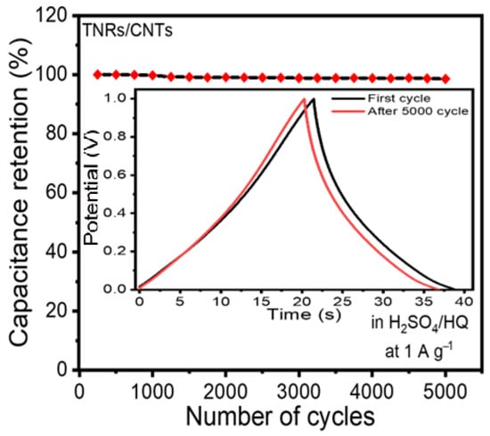
Figure 6.
Stability of the electrode’s performance. The electrode retained 95.5 percent of its initial capacitance after 5000 cycles. The inset shows the first and last cycle for the charge/discharge curves.
4. Conclusions
Chemical vapor deposition was used after the hydrothermal method to create titanium dioxide nanoribbons (TNRs) and multi-walled carbon nanotubes (MWCNTs). The morphological characterization proved that the MWCNTs were grown in the porous pits on the surface of one phase of the TiO2-B nanoribbons to create a network-like structure in the nanocomposite. TNR/CNTs were used as the electrode, and H2SO4 or (H2SO4/HQ) as the electrolyte, resulting in a supercapacitor with high specific capacitance, a long cycle life, a small self-discharge process, and a high energy and power density. The TNR/CNT produced a gravimetric capacitance of 33.33 F g−1 in a two-electrode supercapacitor arrangement, which was increased to 68.18 F g−1 in a redox-active electrolyte of H2SO4/HQ. With 97.5% capacitor retention after 5000 cycles, the TNR/CNT supercapacitor also exhibited excellent cyclic stability. These findings suggest that the TNR/CNT supercapacitor may have an impact on the functionality of upcoming portable energy storage technologies.
Author Contributions
Conceptualization, M.B., M.S. and A.G.; Methodology, M.S. and A.G.; Validation, M.S. and A.G.; Formal analysis, M.S. and A.G.; Investigation, M.B., M.S. and A.G.; Resources, M.B., M.S. and A.G.; Data curation, M.B., M.S. and A.G.; Writing—original draft preparation, M.S. and A.G.; Writing—review and editing, M.B., M.S. and A.G.; Visualization, M.B., M.S. and A.G.; Project administration, M.S.; Funding acquisition, M.S. All authors have read and agreed to the published version of the manuscript.
Funding
This research received no external funding.
Institutional Review Board Statement
Not applicable.
Informed Consent Statement
Not applicable.
Data Availability Statement
Not applicable.
Conflicts of Interest
The authors declare no conflict of interest.
References
- Kim, B.C.; Hong, J.; Wallace, G.G.; Park, H.S. Recent progress in flexible electrochemical capacitors: Electrode materials, device configuration and functions. Adv. Energy Mater. 2015, 5, 1500959. [Google Scholar] [CrossRef]
- Béguin, F.; Presser, V.; Balducci, A.; Frackowiak, E. Supercapacitors: Carbons and electrolytes for advanced supercapacitors. Adv. Mater. 2014, 26, 2283. [Google Scholar] [CrossRef] [PubMed]
- Wang, F.; Wu, X.; Yuan, X.; Liu, Z.; Zhang, Y.; Fu, L.; Zhu, Y.; Zhou, Q.; Wu, Y.; Huang, W. Latest advances in supercapacitors: From new electrode materials to novel device designs. Chem. Soc. Rev. 2017, 46, 6816–6854. [Google Scholar] [CrossRef] [PubMed]
- Zeyuan, C.; Wei, B. A perspective: Carbon nanotube macro-films for energy storage. Energy Environ. Sci. 2013, 6, 3183–3201. [Google Scholar]
- Chen, H.; Zeng, S.; Chen, M.; Zhang, Y.; Li, Q. Fabrication and functionalization of carbon nanotube films for high-performance flexible supercapacitors. Carbon 2015, 92, 271–296. [Google Scholar] [CrossRef]
- Clement, R.C.; Prasanth, R. Advent of TiO2 nanotubes as supercapacitor electrode. J. Electrochem. Soc. 2018, 165, E345. [Google Scholar]
- Selvakumar, M.; Bhat, D.K. Microwave synthesized nanostructured TiO2-activated carbon composite electrodes for supercapacitor. Appl. Surf. Sci. 2012, 263, 236–241. [Google Scholar] [CrossRef]
- Su, H.; Wang, T.; Zhang, S.; Song, J.; Mao, C.; Niu, H.; Jin, B.; Wu, J.; Tian, Y. Facile synthesis of polyaniline/TiO2/graphene oxide composite for high performance supercapacitors. Solid State Sci. 2012, 14, 677–681. [Google Scholar] [CrossRef]
- Xiang, C.; Li, M.; Zhi, M.; Manivannan, A.; Wu, N. Reduced graphene oxide/titanium dioxide composites for supercapacitor electrodes: Shape and coupling effects. J. Mater. Chem. 2012, 22, 19161–19167. [Google Scholar] [CrossRef]
- Ramadoss, A.; Kim, G.-S.; Kim, S.J. Fabrication of reduced graphene oxide/TiO2 nanorod/reduced graphene oxide hybrid nanostructures as electrode materials for supercapacitor applications. CrystEngComm 2013, 15, 10222–10229. [Google Scholar] [CrossRef]
- Ramadoss, A.; Kim, S.J. Improved activity of a graphene—TiO2 hybrid electrode in an electrochemical supercapacitor. Carbon 2013, 63, 434–445. [Google Scholar] [CrossRef]
- Sankapal, B.R.; Gajare, H.B.; Dubal, D.P.; Gore, R.B.; Salunkhe, R.R.; Ahn, H. Presenting highest supercapacitance for TiO2/MWNTs nanocomposites: Novel method. Chem. Eng. J. 2014, 247, 103–110. [Google Scholar] [CrossRef]
- Ke, Q.; Liao, Y.; Yao, S.; Song, L.; Xiong, X. A three-dimensional TiO2/graphene porous composite with nano-carbon deposition for supercapacitor. J. Mater. Sci. 2016, 51, 2008–2016. [Google Scholar] [CrossRef]
- Yan, L.; Xu, Y.; Zhou, M.; Chen, G.; Deng, S.; Smirnov, S.; Luo, H.; Zou, G. Porous TiO2 conformal coating on carbon nanotubes as energy storage materials. Electrochim. Acta 2015, 169, 73–81. [Google Scholar] [CrossRef]
- Faraji, M. Three-dimensional nanostructures of multiwalled carbon nanotubes/graphene oxide/TiO2 nanotubes for supercapacitor applications. Appl. Phys. A 2016, 122, 697. [Google Scholar] [CrossRef]
- Li, Q.; Zhang, J.; Liu, B.; Li, M.; Liu, R.; Li, X.; Ma, H.; Yu, S.; Wang, L.; Zou, Y.; et al. Synthesis of High-Density Nanocavities inside TiO2-B Nanoribbons and Their Enhanced Electrochemical Lithium Storage Properties. Inorg. Chem. 2008, 47, 9870–9873. [Google Scholar] [CrossRef] [PubMed]
- Wen, J.; Chu, W.; Jiang, C.; Tong, D. Growth of carbon nanotubes on the novel FeCo-Al2O3 catalyst prepared by ultrasonic coprecipitation. J. Nat. Gas Chem. 2010, 19, 156–160. [Google Scholar] [CrossRef]
- Vilaça, P.; Wayne, T. Friction stir welding technology. In Structural Connections for Lightweight Metallic Structures; Springer: Berlin/Heidelberg, Germany, 2011; pp. 85–124. [Google Scholar]
- Li, Y.; Zhang, X.; Luo, J.; Huang, W.; Cheng, J.; Luo, Z.; Li, T.; Liu, F.; Xu, G.; Ke, X.; et al. Purification of CVD synthesized single-wall carbon nanotubes by different acid oxidation treatments. Nanotechnology 2004, 15, 1645. [Google Scholar] [CrossRef]
- Mohamed, S.; Ashraf, A.M.; Abukhadra, M.R. TiO2 nanoribbons/carbon nanotubes composite with enhanced photocatalytic activity: Fabrication, characterization and application. Sci. Rep. 2018, 8, 781. [Google Scholar]
- Wang, Y.; Panzik, J.E.; Kiefer, B.; Lee, K.K.M. Crystal structure of graphite under room-temperature compression and decompression. Sci. Rep. 2012, 2, 520. [Google Scholar] [CrossRef]
- Armstrong, G.; Armstrong, A.R.; Canales, J.; Bruce, P.G. Nanotubes with the TiO2-B structure. Chem. Commun. 2005, 19, 2454–2456. [Google Scholar] [CrossRef] [PubMed]
- Akimoto, J.; Chiba, K.; Kijima, N.; Hayakawa, H.; Hayashi, S.; Gotoh, Y.; Idemoto, Y. Soft-chemical synthesis and electrochemical property of H2Ti12O25 as a negative electrode material for rechargeable lithium-ion batteries. J. Electrochem. Soc. 2011, 158, A546. [Google Scholar] [CrossRef]
- Zhou, W.; Gai, L.; Hu, P.; Cui, J.; Liu, X.; Wang, D.; Li, G.; Jiang, H.; Liu, D.; Liu, H.; et al. Phase transformation of TiO2 nanobelts and TiO2 (B)/anatase interface heterostructure nanobelts with enhanced photocatalytic activity. CrystEngComm 2011, 13, 6643–6649. [Google Scholar] [CrossRef]
- Altowyan, A.S.; Shaban, M.; Abdelkarem, K.; El Sayed, A.M. The Impact of Co Doping and Annealing Temperature on the Electrochemical Performance and Structural Characteristics of SnO2 Nanoparticulate Photoanodes. Materials 2022, 15, 6534. [Google Scholar] [CrossRef]
- Altowyan, A.S.; Shaban, M.; Abdelkarem, K.; El Sayed, A.M. The Influence of Electrode Thickness on the Structure and Water Splitting Performance of Iridium Oxide Nanostructured Films. Nanomaterials 2022, 12, 3272. [Google Scholar] [CrossRef] [PubMed]
- Shaban, M.; Mona, M.; El Sayed, A.M. Structural, optical, and photocatalytic properties of the spray deposited nanoporous CdS thin films; influence of copper doping, annealing and deposition parameters. Mater. Sci. Semicond. Process. 2016, 56, 329–343. [Google Scholar] [CrossRef]
- Gonçalves, N.; Carvalho, J.; Lima, Z.; Sasaki, J. Size–strain study of NiO nanoparticles by X-ray powder diffraction line broadening. Mater. Lett. 2012, 72, 36–38. [Google Scholar] [CrossRef]
- Santara, B.; Giri, P.K.; Imakita, K.; Fujii, M. Evidence of oxygen vacancy induced room temperature ferromagnetism in solvothermally synthesized undoped TiO2 nanoribbons. Nanoscale 2013, 5, 5476–5488. [Google Scholar] [CrossRef] [PubMed]
- Pan, H.; Poh, C.K.; Feng, Y.P.; Lin, J. Supercapacitor electrodes from tubes-in-tube carbon nanostructures. Chem. Mater. 2007, 19, 6120–6125. [Google Scholar] [CrossRef]
- Kim, K.-S.; Park, S.-J. Synthesis and high electrochemical performance of polyaniline/MnO2-coated multi-walled carbon nanotube-based hybrid electrodes. J. Solid State Electrochem. 2012, 16, 2751–2758. [Google Scholar] [CrossRef]
- Ko, J.M.; Kwang, S.R.; Kim, S.; Kwang, M.K. Supercapacitive properties of composite electrodes consisting of polyaniline, carbon nanotube and RuO2. J. Appl. Electrochem. 2009, 39, 1331–1337. [Google Scholar] [CrossRef]
- Shao, Y.; El-Kady, M.F.; Lin, C.-W.; Zhu, G.; Marsh, K.L.; Hwang, J.Y.; Zhang, Q.; Li, Y.; Kaner, R.B. 3D freeze-casting of cellular graphene films for ultrahigh-power-density supercapacitors. Adv. Mater. 2016, 28, 6719–6726. [Google Scholar] [CrossRef]
- Tao, Y.; Xie, X.; Lv, W.; Tang, D.; Kong, D.; Huang, Z.; Nishihara, H.; Ishii, T.; Li, B.; Golberg, D.; et al. Towards ultrahigh volumetric capacitance: Graphene derived highly dense but porous carbons for supercapacitors. Sci. Rep. 2013, 3, 2975. [Google Scholar] [CrossRef] [PubMed]
- Roldán, S.; Blanco, C.; Granda, M.; Menéndez, R.; Santamaria, R. Towards a further generation of high-energy carbon-based capacitors by using redox-active electrolytes. Angew. Chem. Int. Ed. 2011, 50, 1699–1701. [Google Scholar] [CrossRef] [PubMed]
- Kötz, R.; Carlen, M. Principles and applications of electrochemical capacitors. Electrochim. Acta 2000, 45, 2483–2498. [Google Scholar] [CrossRef]
- Rakhi, R.B.; Chen, W.; Hedhili, M.N.; Cha, D.; Alshareefet, H.N. Enhanced rate performance of mesoporous Co3O4 nanosheet supercapacitor electrodes by hydrous RuO2 nanoparticle decoration. ACS Appl. Mater. Interfaces 2014, 6, 4196–4206. [Google Scholar] [CrossRef]
- Wang, K.; Wu, H.; Meng, Y.; Zhang, Y.; Wei, Z. Integrated energy storage and electrochromic function in one flexible device: An energy storage smart window. Energy Environ. Sci. 2012, 5, 8384–8389. [Google Scholar] [CrossRef]
- Patil, J.V.; Mali, S.S.; Shaikh, J.S.; Bhat, T.S.; Hong, C.K.; Kim, J.H.; Patil, P.S. Hydrothermally grown 3D hierarchical TiO2 based on electrochemically anodized 1D TiO2 nanostructure for supercapacitor. Appl. Phys. A 2018, 124, 592. [Google Scholar] [CrossRef]
- Heng, I.; Lai, C.W.; Juan, J.C.; Numan, A.; Iqbal, J.; Teo, E.Y.L. Low-temperature synthesis of TIO2 nanocrystals for high performance electrochemical supercapacitors. Ceram. Int. 2019, 45, 4990–5000. [Google Scholar] [CrossRef]
Disclaimer/Publisher’s Note: The statements, opinions and data contained in all publications are solely those of the individual author(s) and contributor(s) and not of MDPI and/or the editor(s). MDPI and/or the editor(s) disclaim responsibility for any injury to people or property resulting from any ideas, methods, instructions or products referred to in the content. |
© 2023 by the authors. Licensee MDPI, Basel, Switzerland. This article is an open access article distributed under the terms and conditions of the Creative Commons Attribution (CC BY) license (https://creativecommons.org/licenses/by/4.0/).