
Fabrication and Optimisation of Ti-6Al-4V Lattice-Structured Total Shoulder Implants Using Laser Additive Manufacturing


 ,
,  , ,
, ,  and
and
Abstract
:1. Introduction
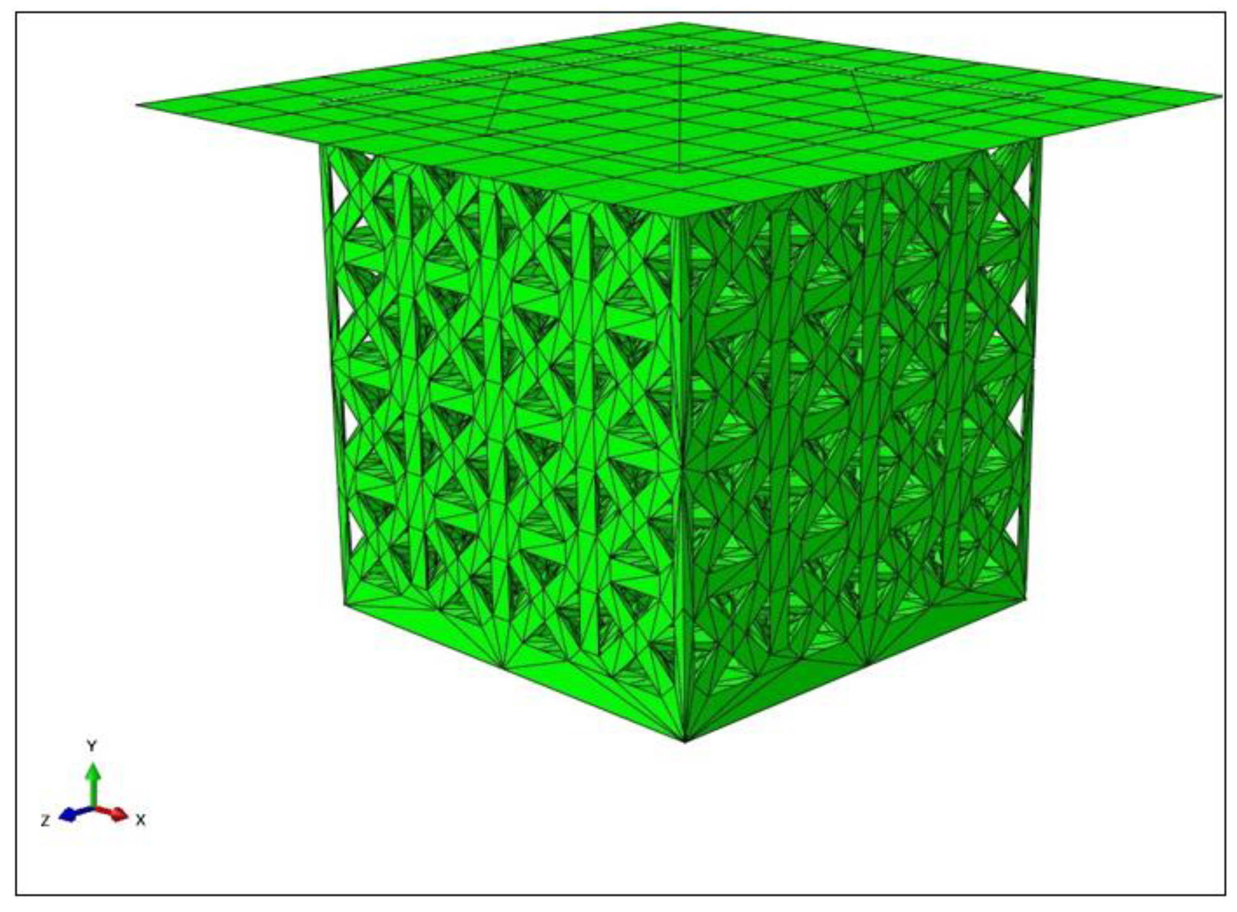
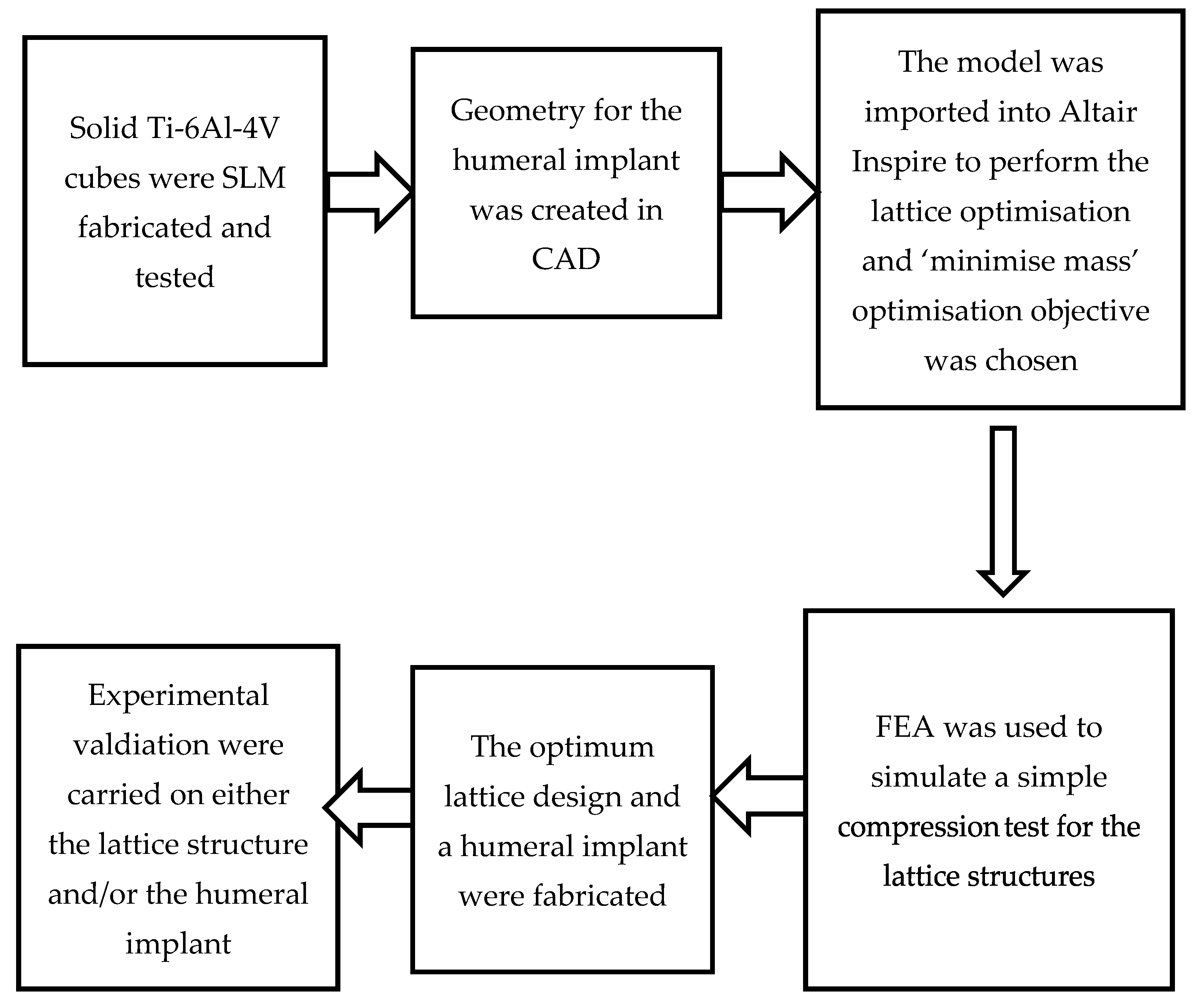
2. Methodology
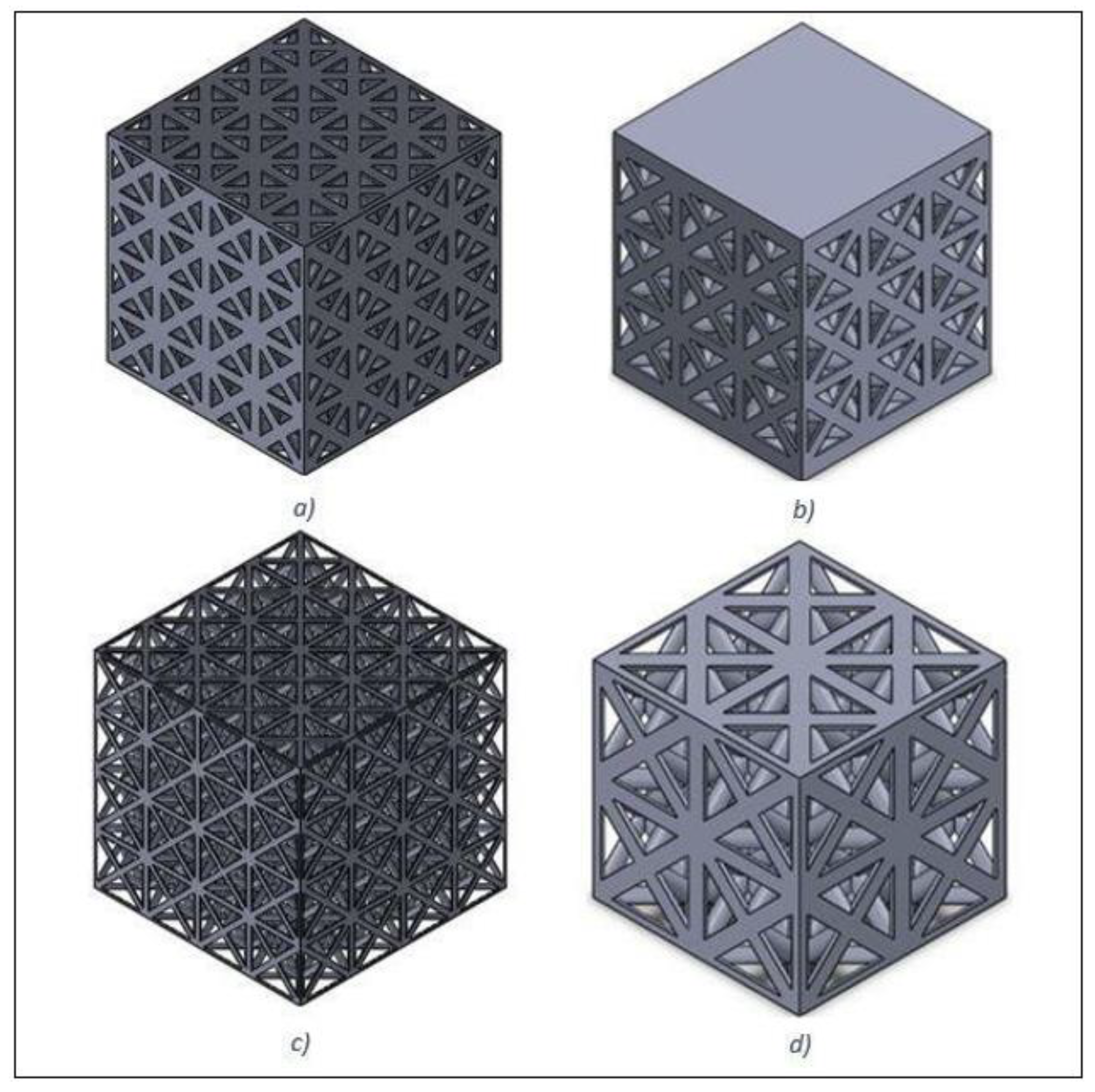
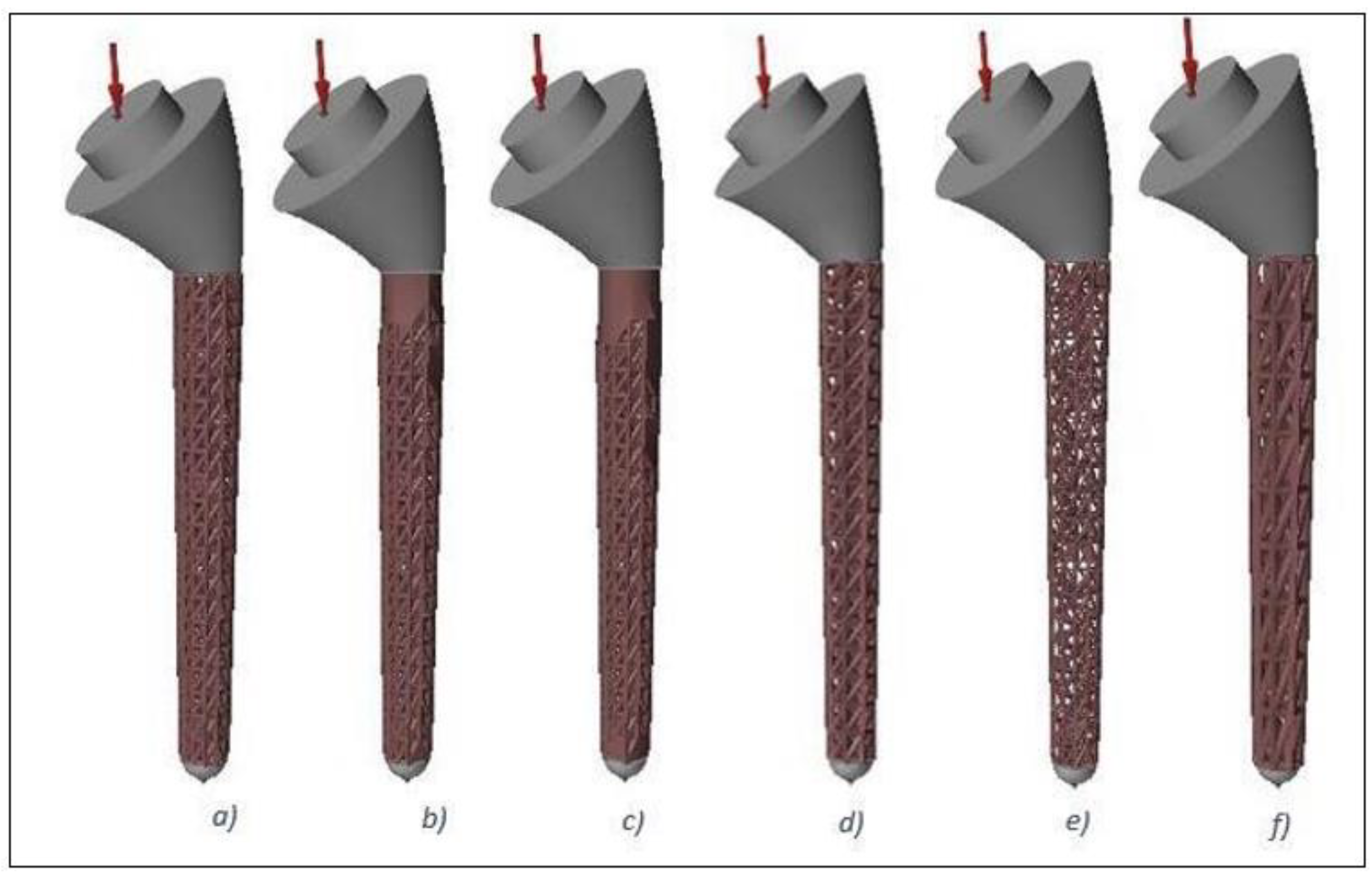
2.1. Design and Modelling
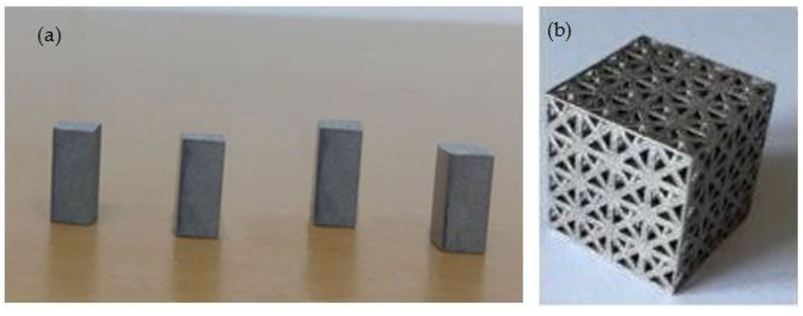
2.2. Fabrication and Characterisation
3. Results and Discussion
4. Conclusions
- Implementation of the lattice design significantly decreased the implant weight by up to 44% compared to a fully solid implant.
- The FEA results suggested Young’s moduli for the examined lattice structures of between 2 and 13 GPa, which was comparable to that of human bones.
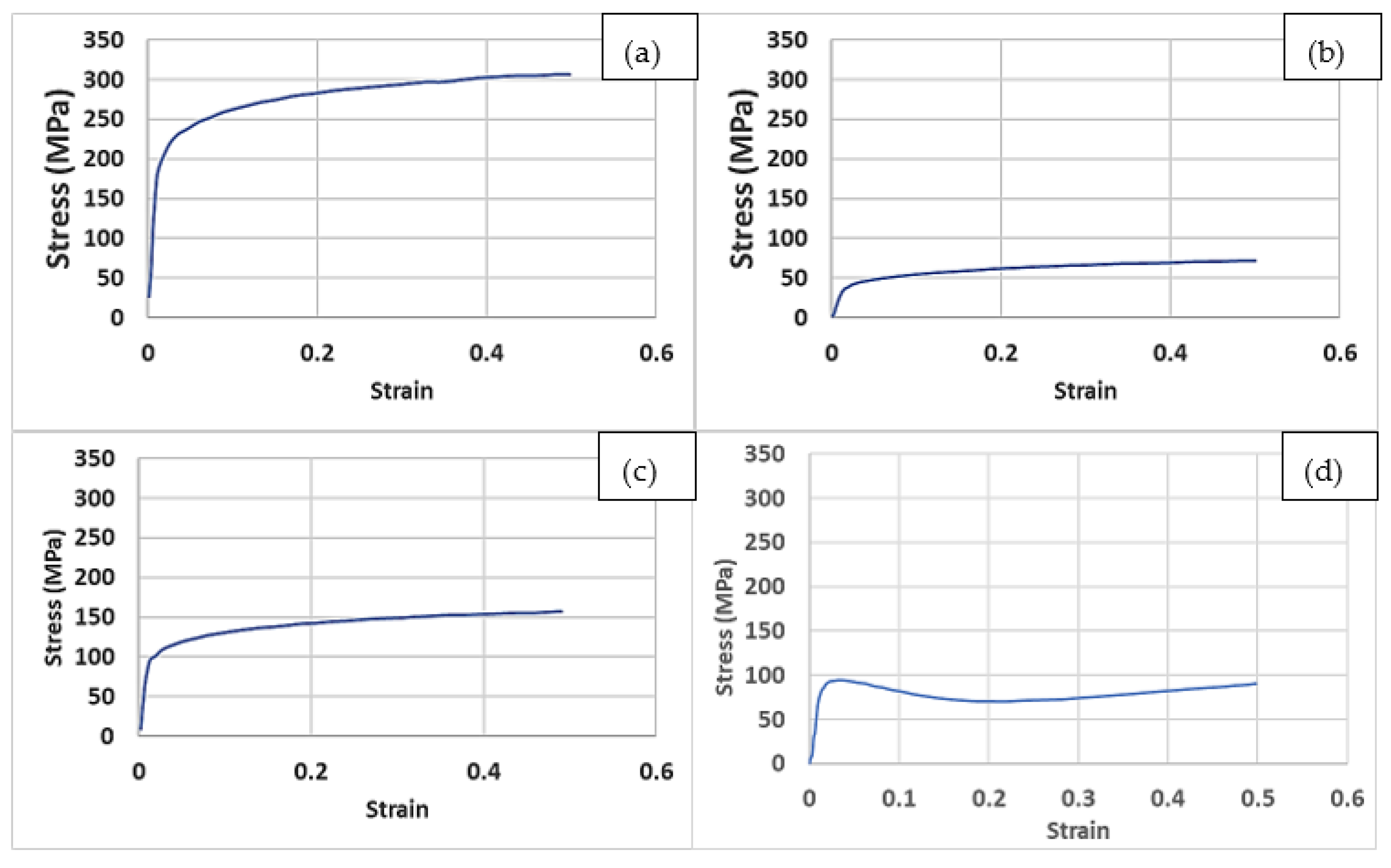
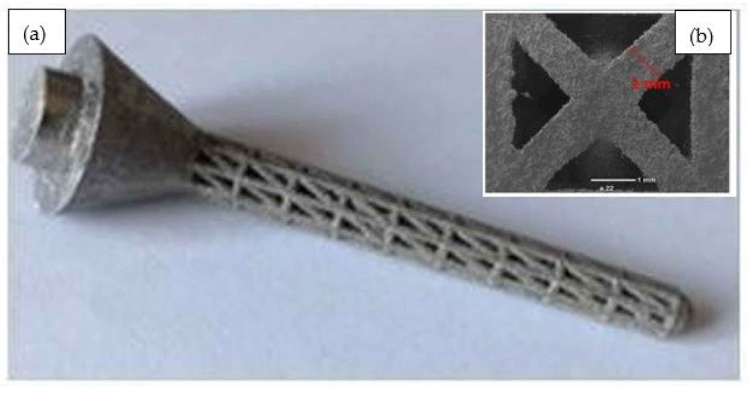
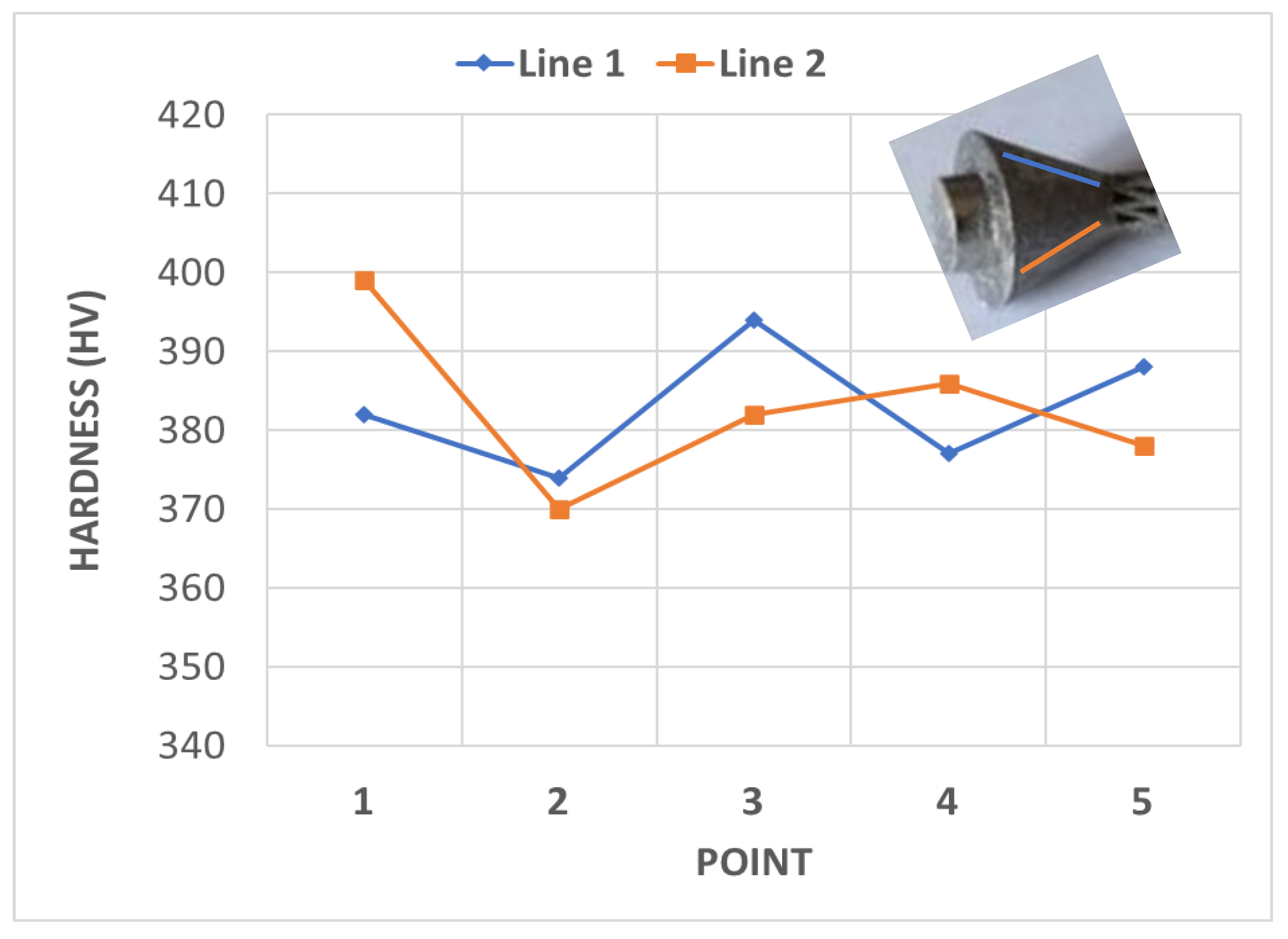
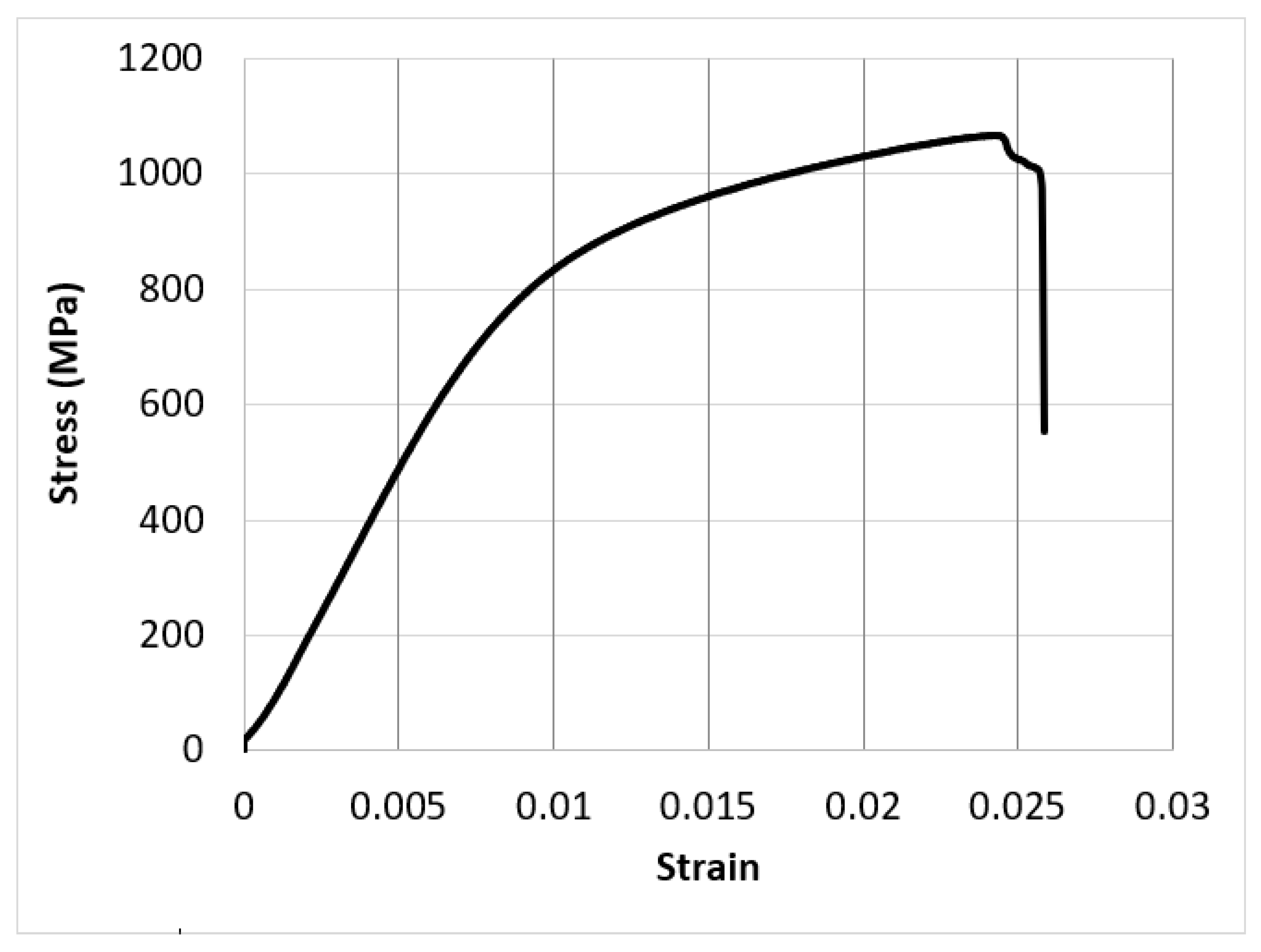
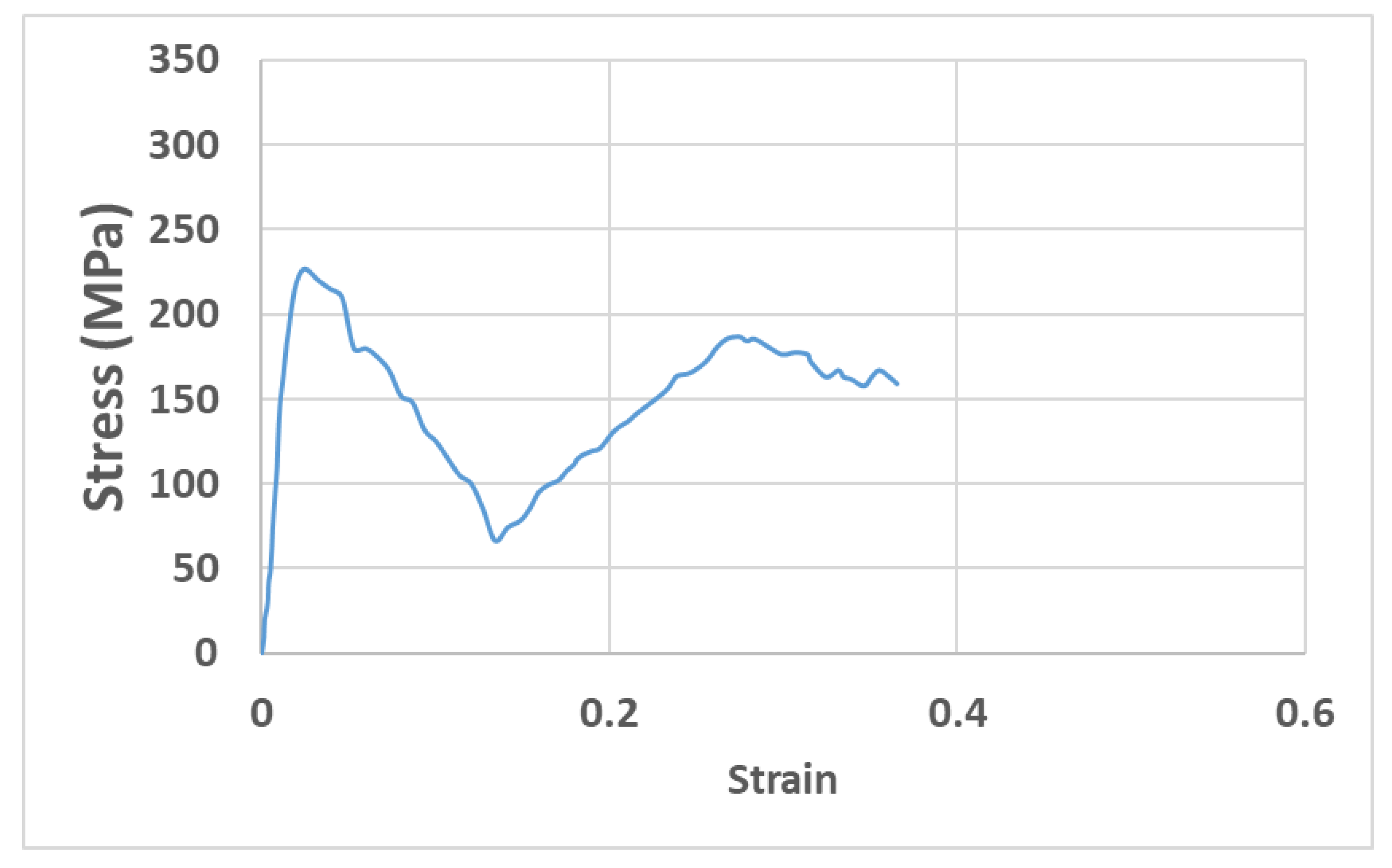
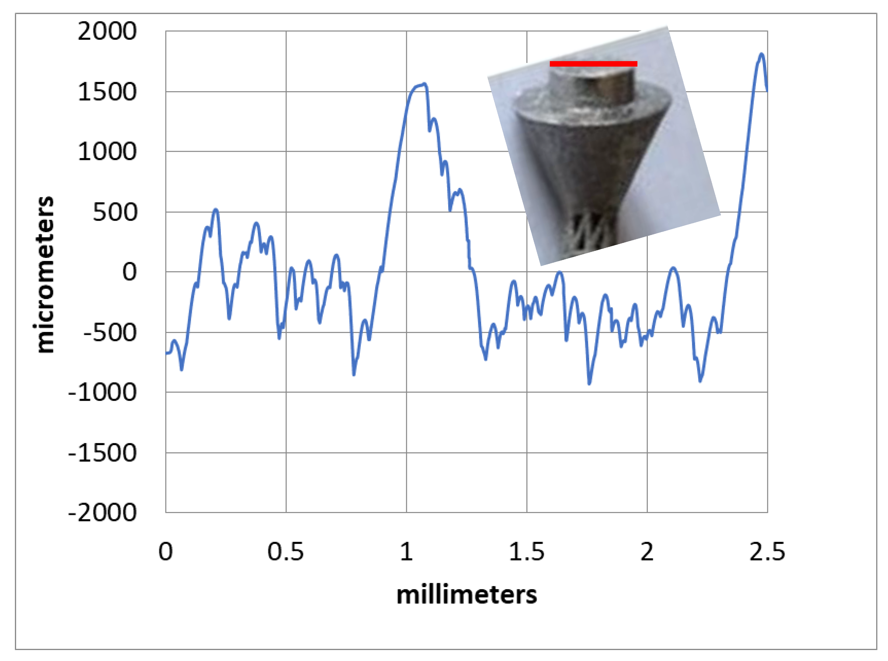
- The experimental results showed that an LPBF-fabricated Ti-6Al-4V lattice structure with a 5 mm strut length, 1 mm strut diameter, and 100% lattice in the design space had a yield strength of 200 MPa, an elastic modulus of 11.8 GPa, a hardness of 380 HV, a surface roughness of 9.3 µm, and a surface area/volume ratio of 3.7 mm−1. These properties were suggested to be suitable for orthopaedic structures with a stiffness close to that of human bones and for improved bone ingrowth characteristics.
Author Contributions
Funding
Institutional Review Board Statement
Informed Consent Statement
Data Availability Statement
Acknowledgments
Conflicts of Interest
References
- Erickson, B.J.; Chalmers, P.N.; Denard, P.J.; Gobezie, R.; Romeo, A.A.; Lederman, E.S. Current state of short-stem implants in total shoulder arthroplasty: A systematic review of the literature. JSES Int. 2020, 4, 114–119. [Google Scholar] [CrossRef] [PubMed]
- Verestiuc, L.; Spataru, M.-C.; Baltatu, M.S.; Butnaru, M.; Solcan, C.; Sandu, A.V.; Voiculescu, I.; Geanta, V.; Vizureanu, P. New Ti–Mo–Si materials for bone prosthesis applications. J. Mech. Behav. Biomed. Mater. 2021, 113, 104198. [Google Scholar] [CrossRef] [PubMed]
- Razfar, N.; Reeves, J.M.; Langohr, D.G.; Willing, R.; Athwal, G.S.; Johnson, J.A. Comparison of proximal humeral bone stresses between stemless, short stem, and standard stem length: A finite element analysis. J. Shoulder Elb. Surg. 2016, 25, 1076–1083. [Google Scholar] [CrossRef] [PubMed]
- Mohammed, A.; Elshaer, A.; Sareh, P.; Elsayed, M.; Hassanin, H. Additive manufacturing technologies for drug delivery applications. Int. J. Pharm. 2020, 580, 119245. [Google Scholar] [CrossRef] [PubMed]
- Hassanin, H.; Alkendi, Y.; Elsayed, M.; Essa, K.; Zweiri, Y. Controlling the properties of additively manufactured cellular structures using machine learning approaches. Adv. Eng. Mater. 2020, 22, 1901338. [Google Scholar] [CrossRef]
- Hassanin, H.; Ahmed El-Sayed, M.; ElShaer, A.; Essa, K.; Jiang, K. Microfabrication of net shape zirconia/alumina nanocomposite micro parts. Nanomaterials 2018, 8, 593. [Google Scholar] [CrossRef] [Green Version]
- Elsayed, M.; Ghazy, M.; Youssef, Y.; Essa, K. Optimization of SLM process parameters for Ti6Al4V medical implants. Rapid Prototyp. J. 2019, 25. [Google Scholar] [CrossRef] [Green Version]
- Sandu, A.V.; Baltatu, M.S.; Nabialek, M.; Savin, A.; Vizureanu, P. Characterization and mechanical proprieties of new TiMo alloys used for medical applications. Materials 2019, 12, 2973. [Google Scholar] [CrossRef] [Green Version]
- Boileau, P.; Melis, B.; Duperron, D.; Moineau, G.; Rumian, A.P.; Han, Y. Revision surgery of reverse shoulder arthroplasty. J. Shoulder Elb. Surg. 2013, 22, 1359–1370. [Google Scholar] [CrossRef]
- Liu, Y.; Li, X.; Zhang, L.C.; Sercombe, T. Processing and properties of topologically optimised biomedical Ti–24Nb–4Zr–8Sn scaffolds manufactured by selective laser melting. Mater. Sci. Eng. A 2015, 642, 268–278. [Google Scholar] [CrossRef]
- Jamari, J.; Ammarullah, M.I.; Saad, A.P.M.; Syahrom, A.; Uddin, M.; van der Heide, E.; Basri, H. The effect of bottom profile dimples on the femoral head on wear in metal-on-metal total hip arthroplasty. J. Funct. Biomater. 2021, 12, 38. [Google Scholar] [CrossRef] [PubMed]
- Hassanin, H.; Al-Kinani, A.A.; ElShaer, A.; Polycarpou, E.; El-Sayed, M.A.; Essa, K. Stainless steel with tailored porosity using canister-free hot isostatic pressing for improved osseointegration implants. J. Mater. Chem. B 2017, 5, 9384–9394. [Google Scholar] [CrossRef] [Green Version]
- Ammarullah, M.I.; Afif, I.Y.; Maula, M.I.; Winarni, T.I.; Tauviqirrahman, M.; Akbar, I.; Basri, H.; van der Heide, E.; Jamari, J. Tresca Stress Simulation of Metal-on-Metal Total Hip Arthroplasty during Normal Walking Activity. Materials 2021, 14, 7554. [Google Scholar] [CrossRef] [PubMed]
- Kang, D.; Park, S.; Son, Y.; Yeon, S.; Kim, S.H.; Kim, I. Multi-lattice inner structures for high-strength and light-weight in metal selective laser melting process. Mater. Des. 2019, 175, 107786. [Google Scholar] [CrossRef]
- Azman, A.H. Method for Integration of Lattice Structures in Design for Additive Manufacturing. Ph.D. Thesis, Université Grenoble Alpes, Grenoble, France, 2017. [Google Scholar]
- El-Sayed, M.A.; Essa, K.; Ghazy, M.; Hassanin, H. Design optimization of additively manufactured titanium lattice structures for biomedical implants. Int. J. Adv. Manuf. Technol. 2020, 110, 2257–2268. [Google Scholar] [CrossRef]
- Peyrton, J.; Avérous, L. Structure-properties relationships of cellular materials from biobased polyurethane foams. Mater. Sci. Eng. R Rep. 2021, 145, 100608. [Google Scholar] [CrossRef]
- du Plessis, A.; Razavi, S.M.J.; Benedetti, M.; Murchio, S.; Leary, M.; Watson, M.; Bhate, D.; Berto, F. Properties and applications of additively manufactured metallic cellular materials: A review. Prog. Mater. Sci. 2021, 125, 100918. [Google Scholar] [CrossRef]
- Rashed, M.; Ashraf, M.; Mines, R.; Hazell, P.J. Metallic microlattice materials: A current state of the art on manufacturing, mechanical properties and applications. Mater. Des. 2016, 95, 518–533. [Google Scholar] [CrossRef]
- Hassanin, H.; Abena, A.; Elsayed, M.A.; Essa, K. 4D printing of NiTi auxetic structure with improved ballistic performance. Micromachines 2020, 11, 745. [Google Scholar] [CrossRef]
- Essa, K.; Modica, F.; Imbaby, M.; El-Sayed, M.A.; ElShaer, A.; Jiang, K.; Hassanin, H. Manufacturing of metallic micro-components using hybrid soft lithography and micro-electrical discharge machining. Int. J. Adv. Manuf. Technol. 2017, 91, 445–452. [Google Scholar] [CrossRef] [Green Version]
- Essa, K.; Sabouri, A.; Butt, H.; Basuny, F.H.; Ghazy, M.; El-Sayed, M.A. Laser additive manufacturing of 3D meshes for optical applications. PLoS ONE 2018, 13, e0192389. [Google Scholar] [CrossRef] [PubMed]
- Hassanin, H.; Modica, F.; El-Sayed, M.A.; Liu, J.; Essa, K. Manufacturing of Ti–6Al–4V micro-implantable parts using hybrid selective laser melting and micro-electrical discharge machining. Adv. Eng. Mater. 2016, 18, 1544–1549. [Google Scholar] [CrossRef] [Green Version]
- Sing, S.; Huang, S.; Goh, G.; Goh, G.; Tey, C.; Tan, J.; Yeong, W. Emerging metallic systems for additive manufacturing: In-situ alloying and multi-metal processing in laser powder bed fusion. Prog. Mater. Sci. 2021, 119, 100795. [Google Scholar] [CrossRef]
- Bălţatu, M.; Vizureanu, P.; Goanţă, V.; Ţugui, C.; Voiculescu, I. Mechanical tests for Ti-based alloys as new medical materials. In Proceedings of the IOP Conference Series: Materials Science and Engineering, Iasi, Romania, 16–17 May 2019; p. 012029. [Google Scholar]
- Onal, E.; Frith, J.E.; Jurg, M.; Wu, X.; Molotnikov, A. Mechanical Properties and In Vitro Behavior of Additively Manufactured and Functionally Graded Ti6Al4V Porous Scaffolds. Metals 2018, 8, 200. [Google Scholar] [CrossRef] [Green Version]
- Burton, H.E.; Eisenstein, N.M.; Lawless, B.M.; Jamshidi, P.; Segarra, M.A.; Addison, O.; Shepherd, D.E.T.; Attallah, M.M.; Grover, L.M.; Cox, S.C. The design of additively manufactured lattices to increase the functionality of medical implants. Mater. Sci. Eng. C 2019, 94, 901–908. [Google Scholar] [CrossRef] [Green Version]
- Parthasarathy, J.; Starly, B.; Raman, S. A design for the additive manufacture of functionally graded porous structures with tailored mechanical properties for biomedical applications. J. Manuf. Processes 2011, 13, 160–170. [Google Scholar] [CrossRef]
- Li, D.; Liao, W.; Dai, N.; Dong, G.; Tang, Y.; Xie, Y.M. Optimal design and modeling of gyroid-based functionally graded cellular structures for additive manufacturing. Comput.-Aided Des. 2018, 104, 87–99. [Google Scholar] [CrossRef]
- Panesar, A.; Abdi, M.; Hickman, D.; Ashcroft, I. Strategies for functionally graded lattice structures derived using topology optimisation for Additive Manufacturing. Addit. Manuf. 2018, 19, 81–94. [Google Scholar] [CrossRef]
- Liu, T.; Guessasma, S.; Zhu, J.; Zhang, W.; Belhabib, S. Functionally graded materials from topology optimisation and stereolithography. Eur. Polym. J. 2018, 108, 199–211. [Google Scholar] [CrossRef]
- He, Y.; Burkhalter, D.; Durocher, D.; Gilbert, J.M. Solid-Lattice Hip Prosthesis Design: Applying Topology and Lattice Optimization to Reduce Stress Shielding From Hip Implants. In 2018 Design of Medical Devices Conference; American Society of Mechanical Engineers: Minneapolis, MN, USA, 2018. [Google Scholar]
- Sutradhar, A.; Park, J.; Carrau, D.; Nguyen, T.H.; Miller, M.J.; Paulino, G.H. Designing patient-specific 3D printed craniofacial implants using a novel topology optimization method. Med. Biol. Eng. Comput. 2016, 54, 1123–1135. [Google Scholar] [CrossRef]
- Pearl, M.L. Proximal humeral anatomy in shoulder arthroplasty: Implications for prosthetic design and surgical technique. J. Shoulder Elb. Surg. 2005, 14, S99–S104. [Google Scholar] [CrossRef] [PubMed]
- Affatato, S. Perspectives in Total Hip Arthroplasty: Advances in Biomaterials and Their Tribological Interactions; Elsevier: Amsterdam, The Netherlands, 2014. [Google Scholar]
- Bergmann, G.; Graichen, F.; Bender, A.; Kääb, M.; Rohlmann, A.; Westerhoff, P. In Vivo glenohumeral contact forces—Measurements in the first patient 7 months postoperatively. J. Biomech. 2007, 40, 2139–2149. [Google Scholar] [CrossRef] [PubMed]
- Sharma, S.; Majila, A.N.; Chavan, V.M.; Fernando, D.C.; Patel, R.J.; Babu, S.N. Deformation Response of Titanium Alloy under Static and Dynamic Loading. Procedia Eng. 2017, 173, 1894–1900. [Google Scholar] [CrossRef]
- Krishna, B.V.; Bose, S.; Bandyopadhyay, A. Low stiffness porous Ti structures for load-bearing implants. Acta Biomater. 2007, 3, 997–1006. [Google Scholar] [CrossRef]
- Hibbeler, R.C. Statics and Mechanics of Materials, 4th ed.; Pearson: London, UK, 2014. [Google Scholar]
- Shyha, I.; Gariani, S.; El-Sayed, M.A.; Huo, D. Analysis of Microstructure and Chip Formation When Machining Ti-6Al-4V. Metals 2018, 8, 185. [Google Scholar] [CrossRef] [Green Version]
- Spataru, M.-C.; Cojocaru, F.D.; Sandu, A.V.; Solcan, C.; Duceac, I.A.; Baltatu, M.S.; Voiculescu, I.; Geanta, V.; Vizureanu, P. Assessment of the Effects of Si Addition to a New TiMoZrTa System. Materials 2021, 14, 7610. [Google Scholar] [CrossRef]
- Bender, S.; Chalivendra, V.; Rahbar, N.; El Wakil, S. Mechanical characterization and modeling of graded porous stainless steel specimens for possible bone implant applications. Int. J. Eng. Sci. 2012, 53, 67–73. [Google Scholar] [CrossRef]
- Yan, L.; Yuan, Y.; Ouyang, L.; Li, H.; Mirzasadeghi, A.; Li, L. Improved mechanical properties of the new Ti-15Ta-xZr alloys fabricated by selective laser melting for biomedical application. J. Alloys Compd. 2016, 688, 156–162. [Google Scholar] [CrossRef]
- Morgan, E.F.; Unnikrisnan, G.U.; Hussein, A.I. Bone mechanical properties in healthy and diseased states. Annu. Rev. Biomed. Eng. 2018, 20, 119–143. [Google Scholar] [CrossRef]
- Dumas, M.; Terriault, P.; Brailovski, V. Modelling and characterization of a porosity graded lattice structure for additively manufactured biomaterials. Mater. Des. 2017, 121, 383–392. [Google Scholar] [CrossRef]
- Alla, R.K.; Ginjupalli, K.; Upadhya, N.; Shammas, M.; Ravi, R.K.; Sekhar, R. Surface roughness of implants: A review. Trends Biomater. Artif. Organs 2011, 25, 112–118. [Google Scholar]
- Vandenbroucke, B.; Kruth, J.P. Selective laser melting of biocompatible metals for rapid manufacturing of medical parts. Rapid Prototyp. J. 2007, 13, 196–203. [Google Scholar] [CrossRef]
- Khorasani, A.; Gibson, I.; Awan, U.S.; Ghaderi, A. The effect of SLM process parameters on density, hardness, tensile strength and surface quality of Ti-6Al-4V. Addit. Manuf. 2019, 25, 176–186. [Google Scholar] [CrossRef]
- Öhman, C.; Zwierzak, I.; Baleani, M.; Viceconti, M. Human bone hardness seems to depend on tissue type but not on anatomical site in the long bones of an old subject. Proc. Inst. Mech. Eng. Part H J. Eng. Med. 2013, 227, 200–206. [Google Scholar] [CrossRef] [PubMed]
- Bouxsein, M.L. Bone quality: Where do we go from here? Osteoporos. Int. 2003, 14, 118–127. [Google Scholar] [CrossRef] [PubMed]
- Boivin, G.; Bala, Y.; Doublier, A.; Farlay, D.; Ste-Marie, L.; Meunier, P.; Delmas, P. The role of mineralization and organic matrix in the microhardness of bone tissue from controls and osteoporotic patients. Bone 2008, 43, 532–538. [Google Scholar] [CrossRef]


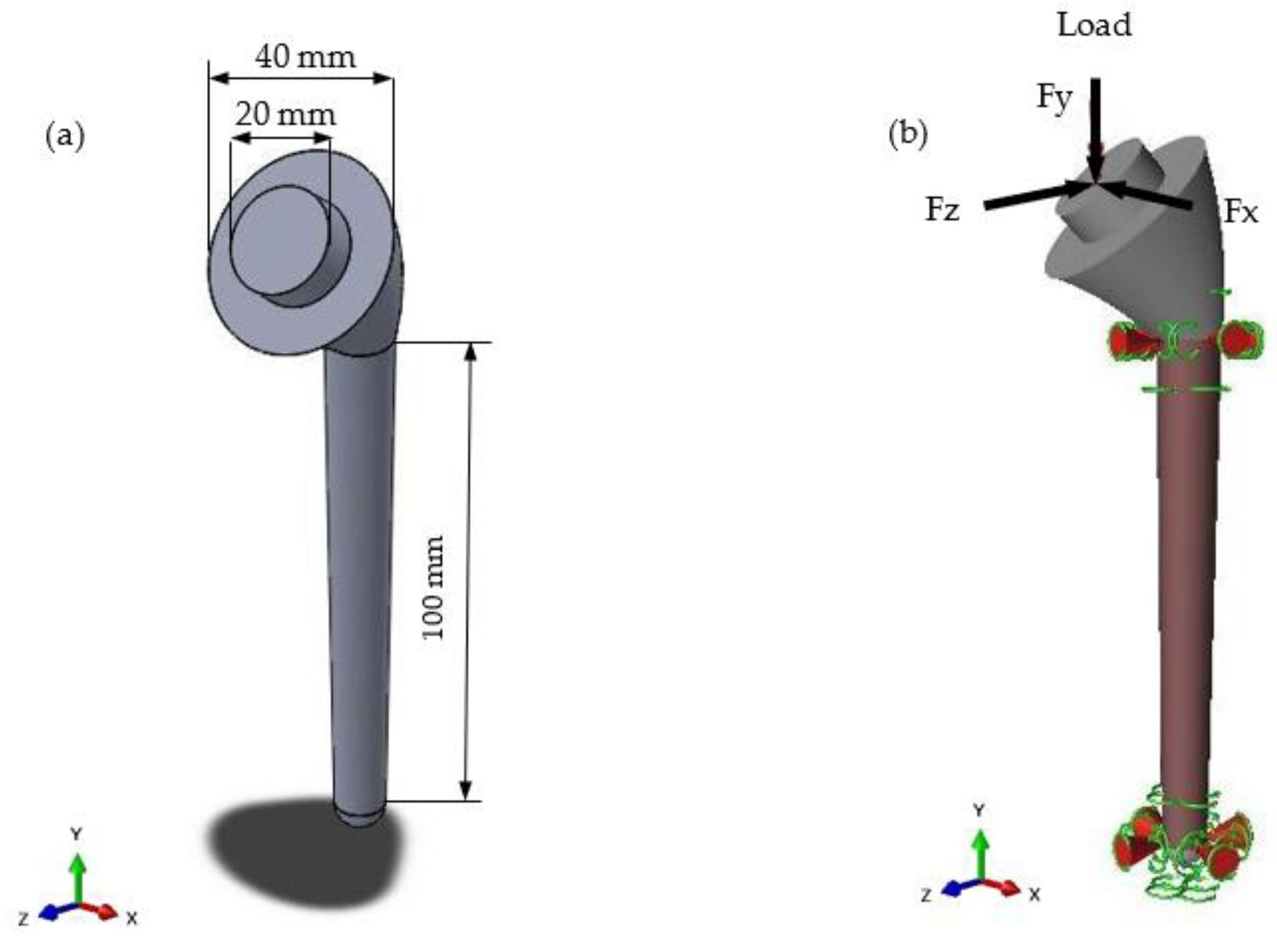
| Load Case | Type of Movement | Force in x-Direction (Fx)/N | Force in y-Direction (Fy)/N | Force in z-Direction (Fz)/N | Resultant Force (F)/N |
|---|---|---|---|---|---|
| Load Case 1 | 75° abduction | 245.25 | −725.94 | −333.54 | 835.69 |
| Load Case 2 | 120° flexion | 225.63 | −1049.67 | −500.31 | 1184.49 |
| Lattice No. | Strut Length (mm) | Strut Diameter (mm) | Percentage Lattice in Design Space |
|---|---|---|---|
| Lattice 1 | 5 | 1 | 100 |
| Lattice 2 | 5 | 1 | 80 |
| Lattice 3 | 5 | 1 | 60 |
| Lattice 4 | 6 | 1 | 100 |
| Lattice 5 | 5 | 0.5 | 100 |
| Lattice 6 | 10 | 1.5 | 100 |
| Load Case | Design | Reduction in Mass % | Maximum Deflection (mm) | Maximum von Mises Stress (MPa) |
|---|---|---|---|---|
| 1 | Lattice 1 | 26.6 | 0.1006 | 82.59 |
| Lattice 2 | 27.8 | 0.0408 | 37.91 | |
| Lattice 3 | 28.5 | 0.0404 | 37.81 | |
| Lattice 4 | 34.7 | 0.1685 | 130.2 | |
| Lattice 5 | 43.5 | 0.3615 | 259.7 | |
| Lattice 6 | 24 | 0.1072 | 83.37 | |
| 2 | Lattice 1 | 26.6 | 0.1508 | 122.8 |
| Lattice 2 | 27.8 | 0.0607 | 57.09 | |
| Lattice 3 | 28.5 | 0.0601 | 56.94 | |
| Lattice 4 | 34.7 | 0.2526 | 193.8 | |
| Lattice 5 | 43.5 | 0.5421 | 389.6 | |
| Lattice 6 | 24 | 0.1607 | 125.2 |
| Lattice Design | Yield Strength (MPa) | Elastic Modulus (GPa) | Surface Area/Volume Ratio (mm−1) |
|---|---|---|---|
| 1 | 200 | 13.4 | 3.71 |
| 4 | 96 | 6.3 | 3.40 |
| 5 | 40 | 2.6 | 8.36 |
| 6 | 90 | 5.9 | 2.99 |
| Ti | V | Al | O |
|---|---|---|---|
| 88.55 | 4.75 | 6.45 | 0.25 |
Publisher’s Note: MDPI stays neutral with regard to jurisdictional claims in published maps and institutional affiliations. |
© 2022 by the authors. Licensee MDPI, Basel, Switzerland. This article is an open access article distributed under the terms and conditions of the Creative Commons Attribution (CC BY) license (https://creativecommons.org/licenses/by/4.0/).
Share and Cite
Bittredge, O.; Hassanin, H.; El-Sayed, M.A.; Eldessouky, H.M.; Alsaleh, N.A.; Alrasheedi, N.H.; Essa, K.; Ahmadein, M. Fabrication and Optimisation of Ti-6Al-4V Lattice-Structured Total Shoulder Implants Using Laser Additive Manufacturing. Materials 2022, 15, 3095. https://doi.org/10.3390/ma15093095
Bittredge O, Hassanin H, El-Sayed MA, Eldessouky HM, Alsaleh NA, Alrasheedi NH, Essa K, Ahmadein M. Fabrication and Optimisation of Ti-6Al-4V Lattice-Structured Total Shoulder Implants Using Laser Additive Manufacturing. Materials. 2022; 15(9):3095. https://doi.org/10.3390/ma15093095
Chicago/Turabian StyleBittredge, Oliver, Hany Hassanin, Mahmoud Ahmed El-Sayed, Hossam Mohamed Eldessouky, Naser A. Alsaleh, Nashmi H. Alrasheedi, Khamis Essa, and Mahmoud Ahmadein. 2022. "Fabrication and Optimisation of Ti-6Al-4V Lattice-Structured Total Shoulder Implants Using Laser Additive Manufacturing" Materials 15, no. 9: 3095. https://doi.org/10.3390/ma15093095
APA StyleBittredge, O., Hassanin, H., El-Sayed, M. A., Eldessouky, H. M., Alsaleh, N. A., Alrasheedi, N. H., Essa, K., & Ahmadein, M. (2022). Fabrication and Optimisation of Ti-6Al-4V Lattice-Structured Total Shoulder Implants Using Laser Additive Manufacturing. Materials, 15(9), 3095. https://doi.org/10.3390/ma15093095