Article

The Influence of Shot Peening and Artificially Ageing Aluminium Alloy 7075 on Corrosion Behaviour

1
Faculty of Mechanical Engineering, University of Ljubljana, Aškerčeva 6, 1000 Ljubljana, Slovenia
2
Faculty of Natural Sciences and Engineering, University of Ljubljana, Aškerčeva 12, 1000 Ljubljana, Slovenia
*
Author to whom correspondence should be addressed.
Materials 2022, 15(9), 3094; https://doi.org/10.3390/ma15093094
Submission received: 22 March 2022 / Revised: 14 April 2022 / Accepted: 23 April 2022 / Published: 25 April 2022

Abstract

:
This paper investigates the corrosion of shot peened AA7075 aluminium alloys aged at different temperatures. The surface integrity of the hardened layer was evaluated with SEM, EDS, differential scanning calorimetry, hardness, and roughness measurements, and in the end also with corrosion resistance tests. The research results indicated that there were significant differences in precipitates distribution between aluminium alloys artificially aged at different temperatures. As the ageing temperature increases, the microhardness decreases, which influences the final roughness condition of the surface layer after shot peening. The results of potentiodynamic polarisation tests indicate that shot peening enables shifting the pitting potential to positive values, which ensures slightly higher corrosion resistance. SEM images confirmed the dissolution of the aluminium matrix near the separated iron-rich phases of the Alx form (Fe, Mn) by the action of galvanic cells.

1. Introduction

Shot peening is a mechanical surface treatment process in which a thin layer of the workpiece surface is mechanically hardened. This surface treatment results in a characteristic surface topography and an increase of dislocation density and compressive residual stresses in the surface layer, which serve to inhibit or slow down the initiation of surface cracks and the growth of fatigue cracks [1,2,3]. Shot peening is a surface treatment commonly used to increase the efficiency of structural components made of high-strength steel [4], aluminium [5], and titanium alloys [6]. It improves fatigue and corrosion resistance and increases resistance to stress corrosion cracking [2,3,7]. The purpose of shot peening of surfaces is to extend the life of various machine parts. Important effects on the surface are closely related to the type of medium used, the available kinetic energy of the accelerated particles, the size and hardness of the particles, and finally, the degree of coverage of individual prints [8,9,10]. These particles are accelerated against the workpiece by means of various impact devices so that they interact with the workpiece surface [11].
The aluminium alloy AA7075 is a high-strength alloy with the addition of 3–7.5 wt.% zinc as the main alloying element in combination with magnesium and copper. These alloys have good formability and fairly good corrosion resistance [12]. The highest strength among all aluminium alloys, which even surpasses some steels, is achieved by artificial ageing [13]. These alloys are widely used for machine parts and load-bearing structures in the aerospace, automotive, and spacecraft industries due to their good weight to strength ratio and relatively good corrosion resistance [14]. However, the dynamic strength of these alloys decreases because they are very susceptible to corrosion fatigue, especially in saline environments [15].
Intermetallic phases formed by solution heat treatment are based on important alloying elements, such as zinc, magnesium, and copper. When the separate phases are concentrated at the boundaries of the crystal grains, they cause intergranular corrosion and increase sensitivity to crack formation and growth due to stress corrosion. Because of the presence of these alloying elements, it is assumed that the separated phases are close in chemical composition to the intermetallic compounds Al2Cu, MgZn2, Al2Mg3Zn3, Mg2Si, Al2CuMg, Al7Cu2Fe, and Al13Fe4 [16,17].
The susceptibility of these alloys to stress corrosion cracking as a result of thermal exposure is due to the migration of magnesium to the crystal grain boundaries and the possible formation of the magnesium-enriched β-phase of Al3Mg2, which is the anode with respect to the aluminium matrix [18,19,20].
High-strength aluminium alloys are susceptible to corrosion fatigue, especially in marine environments, resulting in a significant reduction in the fatigue strength [21]. Corrosion also has a significant influence on the ageing of structural elements made of high-strength aluminium alloys. Aluminium alloy 7075 in the Al–Zn–Mg–Cu alloy system contains a high number of intermetallic particles, i.e., constituent particles, for which heterogeneity of a microstructure has an essential influence on corrosion properties. Corrosion performance of aluminium alloys subjected to surface mechanical treatments has been extensively studied [22,23]. Pandey et al. [24] investigated the effect of the surface nanostructure developed through ultrasonic shot peening on corrosion behavior of aluminium alloy 7075. They found that the enhancement in corrosion resistance of an ultrasonic shot peened specimen is due to rapid development of a uniform, homogeneous, and effective passive layer on the nanostructured surface coupled with refinement of the coarse precipitates. Several researchers did mechanical surface treatment with ultrasonic shot peening. Safyari and Moshtaghi [25] researched the effect of ultrasonic shot peening on the environmental hydrogen embrittlement behavior of the 7075-T6 aluminum alloy. They found out that this treatment decreases the grain size in the surface layer. As a result, there is an increase in the grain boundary area and consequently a decrease in the number of atomic hydrogen trapped per unit length of the grain boundary. Sun et al. [26] studied microstructure, corrosion behavior, and thermal stability of ultrasonic shot peened AA7150. They concluded that for the studied environments, the corrosion resistance of peened AA7150 significantly improved compared with its untreated counterpart. Enhanced localised corrosion resistance is a consequence of the formation of equiaxed nano-grains and microstructure homogenisation on the surface peened layer.
Ye et al. [27] analysed the influence of combined shot peening and plasma electrolytic oxidation treatment on the corrosion fatigue behavior of aluminium alloy 7A85. They concluded that with shot peening as a pre-treatment before plasma electrolytic oxidation treatment, the corrosion fatigue resistance of a multiple treated specimen was improved due to introduction of residual compressive stress, which can inhibit intergranular corrosion.
Our research aims to investigate the influence of shot peening treatment on a chosen aluminium alloy subjected to different ageing temperatures by means of corrosion behavior. The research also addresses the influence of the precipitated phases on the corrosion resistance of the alloy.

2. Experimental Procedure

2.1. Material and Specimen Preparation

The material selected for the analysis was a wrought aluminium alloy, AA7075 (AlZn5.5MgCu), which was supplied as a rolled plate with the dimensions 1500 mm × 1000 mm × 10 mm The chemical composition of the aluminium alloy is given in Table 1.
For metallographic specimen preparation, the specimens were cut to the dimensions of 40 mm × 40 mm × 10 mm on a milling machine. The specimens obtained were first solution heat treated at a temperature of 475 °C for 2 h. Then followed the process of quenching. After quenching, the specimens were artificially aged at three different temperatures (145 °C, 170 °C, and 195 °C) with a uniform ageing time of 8 h. The purpose of ageing at these temperatures was to obtain different densities and sizes of the individual separate phases. The ageing treatment was completed by taking specimens from the furnace and cooling them to the ambient air temperature. Tested specimens were labelled as follows: solution heat treated and quenched (QS), solution heat treated, quenched, and artificially aged at temperature 145 °C (AA145), solution heat treated, quenched, and artificially aged at temperature 170 °C (AA170), solution heat treated, quenched, and artificially aged at temperature 195 °C (AA195).

2.2. Shot Peening Treatment (SP)

A shot peened surface ensures the extension of the life of the machine part. Therefore, it is good to know the influence of individual hardening parameters. We measured surface roughness ten times, in various directions according to the rolling direction. The mean arithmetic value of the specimen roughness (Ra) before shot peening was 0.28 μm. Shot peening was carried out with steel balls designated as S170 with diameters between 350–420 μm. The hardness of the media used was between 420 and 448 HV1. The specimens were clamped in rotating jaws through which high-pressure nozzles moved in an air stream with accelerated ejection of the steel balls. Shot peening was performed at an Almen intensity of 4A with coverage set to 100%. After shot peening, the roughness on all treated specimens increased, as well as the microhardness (Table 2). The thickness of the SP deformation layer is about 0.25 mm.

2.3. Corrosion Tests and X-ray Diffraction Analysis of the Surface

Potentiodynamic tests were performed in the range of −100 mVSCE below the stable potential of the open circuit at a flying speed of 1 mVs−1 in the anode direction. The change of direction from the anode to the cathode was performed at a certain limit value of 1 mA/cm2. Typical potential values were then determined from the polarisation curve. To evaluate the cyclic polarisation, a VoltaLab potentiostat PGZ100 (Radiometer Analytical SAS, Villeurbanne CEDEX, France) and a CNC corrosion cell with a saturated calomel electrode (SCE = +246 mV) as the reference electrode were used. The electrochemical tests were performed in 0.15M (3.5%) NaCl solution with deionised water at pH (6.7 ± 0.1) at room temperature (22 ± 0.5 °C). The tests were performed according to ASTM G5-14 standard [28].
The diffraction spectra were recorded with a PANalytical X’Pert PRO (Malvern Panalytical Ltd., Malvern, UK) instrument in an angular range of 2θ from 15 to 90° using X-rays of the wavelength 0.154059 nm (Cu target) without the use of a monochromator.

3. Results and Discussion

Figure 1 shows the diffraction spectra (XRD spectra) of all four 7075 alloy specimens (Al-Zn-Mg-Cu) tested, i.e., specimen in quenched state (QS), specimen artificially aged at 145 °C (AA145), specimen artificially aged at 170 °C (AA170), and specimen artificially aged at 195 °C (AA195). Among all specimens, the spectra of quenched state and of aged state at 195° C differ the most. In the spectrum, the first sharp diffraction peaks at 2θ angles of 38.5°, 44.8°, 65.1°, 78.2°, and 82.4° are from α-Al. The second less distinct peaks detected in the specimens are deduced as the MgZn2 (M-phase) [29], and these are at the 2θ angles of 19.5°, 20.7°, 34.3°, 37.3°, 39.8°, 40.5°, 41.3°, 42.3°, 46.9°, 53.5°, and 70.4°. The peaks at around 20 degrees do not appear on all curves. The peaks appear only on specimens AA170 and AA195 because the quantitative proportion of the MgZn2 phase is higher due to higher aging temperature.
The second peaks are most visible in the specimen aged at 195° C. Due to their small proportion and the overlapping of some peaks, the presence of the phases Al2CuMg (S-phase), Al6Mg11Zn11 (T-phase), Al7Cu2Fe, which are determined as insoluble impurity-originated particles [30,31,32], and Al6Fe should be further verified by electron microscopy and microanalysis.
Phase equilibria was calculated from the chemical composition using the program Thermo-Calc and is shown in Table 1. Figure 2 shows the proportion of phases as a function of temperature for the investigated aluminium alloy. This can help interpret microstructures as a function of thermal treatment.
In addition, differential scanning calorimetry (DSC) was performed by means of spectral thermal analysis (STA). In Figure 3 cooling curves of the investigated specimens in the quenched and aged state (145 °C, 170° C, and 195 °C) are shown, attributed with phases calculated by Thermo-Calc. As can be seen from the thermodynamic calculation in conjunction with the results of the DSC analysis (Figure 2), solidification of the examined AA7075 alloy begins with the growth of primary α-Al mixed crystals. According to the calculation, this is followed by crystallisation of the remaining melt into the intermetallic phase Al13Fe4 in the temperature range from 604.4 °C to 490 °C. The phase C14_LAVES (designation according to Thermo-Calc) crystallises last at a temperature of 403.5 °C. This is the η-MgZn2 phase. Crystallisation of the T-phase starts at 447 °C, and the S-phase at 463 °C. We can find the similar description of the phases calculated by Thermo-Calc in the research [33,34].
In aluminium alloy 7075, precipitation proceeds as follows: Super Saturated Solid Solution (SSSS) → GP-zones (GPZs) → metastable η’ phase → stable η phase (MgZn2). At peak aged condition, the alloy contains the main precipitates of the metastable η’ phase transformed from GPZs. In the overaged condition, the main precipitates are the stable η phase [35,36].
Figure 4 shows DSC heating curves of the examined AA7075 alloy in different states.
The reference temperatures for the onset of decomposition of the precipitation hardened phases start at almost the same temperatures. The exception is the AA170 specimen, where decomposition begins at a slightly higher temperature. In the process, the intermetallic compounds formed during the ageing process decomposed in the order of precipitation hardening. Table 3 summarises exothermic precipitation and endothermic dissolution peaks for all selected heat treatment procedures. According to the research of Gjønnes and Simensen [37], the exothermic peaks are related to the precipitation phenomena, while the endothermic peaks are associated with the dissolution of precipitate.
From the quenched curve (QS) we can see that it has exothermic precipitation peaks and also endothermic dissolution peaks. It can be observed that the first exothermic precipitation peak is at a temperature 109.6 °C, and the first endothermic dissolution peak is at a temperature of 148.4 °C. The second less pronounced precipitation peak is at 220 °C, and the third exothermic precipitation peak is at 243 °C. The main difference between the quenched specimen and the artificially aged specimens appears in the first endothermic dissolution peaks, which are no longer so pronounced. The specimens aged at 170 °C and 195 °C show a similar trend, while the specimen aged at 145 °C deviates slightly from the previously mentioned specimens.
The endothermic dissolution peak appears at a temperature of about 220 °C, exactly where the exothermic precipitation peak appears in a quenched specimen. The exothermic precipitation peaks of quenched and aged at 145 °C specimens are then almost matched at 243 °C and 247 °C, respectively. The aged specimen has another exothermic precipitation peak at the end at 296 °C. The peak temperature in exothermic curve is an indication of the relative stability of pre-existing precipitates. Therefore, the precipitates responsible for the 1st exothermic peak continually form and grow and become more stable during room temperature ageing and artificial ageing. It also can be seen that the 1st exothermic peak increases with an increase in the ageing temperature. This reflects the rapid growth of zones during artificial ageing because the dissolution temperature is a function of the size of the precipitates. The sizes of the 1st and 2nd endothermic peaks decrease with increasing the artificial ageing temperature, and the 2nd endothermic peak has almost disappeared after ageing at 195 °C. This indicates that the zones are transforming to a more stable phase or dissolving as a more stable phase forms after artificial ageing. We can see that only when ageing at a temperature of 145 °C does a distinctly steep 3rd exothermic peak appear. This indicates that η’ is forming during the artificial ageing. When comparing the quenched state and ageing at 145 °C, we see that the position of the 3rd exothermic peak hardly changes, which indicates that the number density of the η’ precipitates increase during artificial ageing. Similar descriptions of exothermic precipitation peaks and endothermic dissolution peaks are reported in the research [38,39,40,41].
From the curves obtained, it can be concluded that the selected ageing temperatures chosen were too high, since the aluminium alloy shows signs of overageing and can therefore be assigned to the T7 state. Similar conclusions were taken by Takata et al. in his research [42].
Figure 5 shows precipitates in the microstructure of the aluminium alloy obtained at different ageing temperatures. Most precipitates are found at the highest ageing temperature of 195 °C (Figure 5d), occupying as much as 15% of the total surface. Larger precipitates are generated along the boundaries of the crystal grains. The quantity of precipitates in specimens in (a) a quenched state, (b) aged at 145 °C, (c) aged at 170 °C, and (d) aged at 195 °C has the values of 3.63%, 2.93%, 3.05%, and 15.16%, respectively. We can see that there are already quite large precipitates in the quenched state and that they exceed the percentage of precipitates in specimens aged with lower ageing temperatures, i.e., 145 °C and 170 °C. Figure 5a shows that the average size of the precipitates in the quenched state is around 100 nm and that not all of them are dissolved. So, we may conclude that the time of solution heat treatment was too short. With an aging temperature of 145 °C, the amount of precipitates decreases slightly while the average size of precipitates hardly changes (Figure 5b). As the aging temperature rises to 170 °C, as shown in Figure 5c, the amount of precipitates increases negligibly while the average size decreases to about 60–70 nm. These differences are related to the place of sampling. In the case of the highest aging temperature of 195 °C, we can see from Figure 5d that the size of the precipitates is from 30 nm up to about 300 nm. Larger precipitates, which are coarsed, are excreted just beyond the crystal grain boundaries, which also coincides with the study [43]. The main increase at this aging temperature is in the amount of precipitates, as it increases to a level of 15%.
Figure 6 shows the cyclic polarisation curves for the aluminium alloy in different heat treatment conditions. The specimen aged at 145 °C proving to be the most corrosion resistant when compared to the other precipitation hardened states.
In addition to the low corrosion current, the curve is shifted to more positive values of the corrosion potential, which further contributes to corrosion protection. The specimens at higher temperatures come closest to precipitation solidification. In all test cases, a very similar trend of the cyclic polarisation curves was found. Such curve shapes are characteristic of pitting corrosion, which intersects the cathode area with a back fly-over. It is assumed that the tighter the hysteresis loop and the higher the value of the repassivation potential, the greater the resistance of the material to pitting corrosion formation. In general, it can be said that the lower initial surface roughness provides greater corrosion resistance to the material and that higher residual compressive stresses in the material inhibit the formation and spread of corrosion ulcers. Alloys of the 7xxx group are characterised by intergranular corrosion, which takes place at the crystal boundaries where we have precipitates associated with elements of copper or zinc, thus forming an area depleted of these elements. Among the factors influencing the corrosion resistance of aluminium alloys is the presence of chemical element Zn, which forms precipitates η (MgZn2), and is the most critical one [44,45].
Figure 7 shows the cyclic polarisation curves for an aluminium alloy shot peened with an Almen intensity of 4A and coverage set to 100%. The comparison of the corrosion current shows that the lowest currents were from a specimen aged at a temperature of 170 °C (icorr = 0.0079 μAcm−2) and a specimen which was in the quenched state (icorr = 0.0077 μAcm−2). The lower the corrosion current value, the greater the corrosion resistance of the material. Since the corrosion rate calculated per year is also directly related to the corrosion current, we also have the lowest values of material decomposition in these two specimens. The comparison with the age hardened specimen at a temperature of 145 °C shows that the latter has higher corrosion current and thus greater degradation of the material.
The analysis of the results of the electrical potential ΔE1 shows that the specimens in the quenched condition and aged at the lowest selected temperature have the greatest capacity for repassivation regarding the reprotection of corrosion pits during the previous anode overflight. The difference (Δ) between the hardened and unhardened alloy is 16 mV in the case of a quenched specimen and 14 mV in the case of aging at a temperature of 145 °C. At higher aging temperatures, the values are slightly higher, 27 mV at the ageing temperature of 170 °C and 28 mV at the highest temperature of 195 °C. However, in all test cases, the repassivation ability of the age hardened alloy deteriorates. With the help of further analysis of the electrical potential, ΔE2, we can conclude that the most stable and corrosion resistant surface film is obtained in the quenched state of the alloy. There is also the biggest difference in electrical potential between hardened and unhardened specimens, which is 44 mV and is in favour of the hardened specimen. All other ageing temperatures show that the difference (Δ) between the hardened and unhardened alloy is small in all cases, and the surface film is always more stable in unhardened specimens. The expected precipitated MgZn2 phase (M-phase) represents cathode sites with a more positive electrochemical potential with respect to aluminium matrices, α-Al, so that anodic dissolution of the matrix occurs at the crystal boundaries of the precipitates. The dissolution of the aluminium matrix consequently affects the loss of individual separated phases, which explains the formation and development of corrosion damage.
Figure 8 shows further analysis of a quenched and shot peened specimen by EDS. The study shows that specimen preparation—grinding imprints small particles of SiO2, which are strongly bonded with the 7075-T6 matrix (EDS spot 1). When they fall off (EDS spot 2), they pull off the matrix around it too. Analysis of EDS Spot 3 shows that the chemical composition matches the precipitation of Al7Cu2Fe. As mentioned before, AA7075 is an Al–Mg–Zn–Cu alloy material normally comprised of the elements Al, Zn, Cu, Mg, Fe, and Cr (as shown in Table 1). However, in the EDS spectrogram, Si, O, and Ca can also be observed. These foreign materials typically appear as SiO2 or Al2O3, and they come as the remnants of the grinder used for the specimen preparation. SiO2 is chemically stable. It is an acidic oxide, which does not react with general acids or water.
Figure 9 shows the SEM image just below the surface with an analysis of two precipitates. Intermetallic phases formed by solution heat treatment are based on the main alloying elements (Zn, Cu, Mg). When the separated phases are concentrated at the boundaries of the crystal grains, they cause intergranular corrosion and increase sensitivity to crack formation and growth due to stress corrosion. Since Cu (31.24%) is also present, we assume that the separated phases come close to the intermetallic compound Al2Cu in their chemical composition. The occurring intermetallic phases are present in the form of MgZn2, Al2CuMg, Al6Mg11Zn11, Al7Cu2Fe, Al2Mg3Zn3, Al2Cu, and Al13Fe4. Similar results were also presented by Fan et al. in their study [46].
In Figure 10, the separate phases formed after solidification by solution heat treatment were microchemically analysed, and their chemical composition was found to be very close to the intermetallic phase of Al7Cu2Fe. All intermetallic phases in aluminium alloys with iron content are generally classified as impurities. Usually, these excluded phases have rather irregular shapes. Precipitates in the form of Mg2Si represent sites where passivation of the material is difficult, and they are localised sites for corrosion attack. Based on the analysed sites, we can say that these are also present in our specimens. Due to the high density of corrosion currents on the contaminated surface of specimens hardened with steel balls, a heavily corroded surface layer is observed. We can also see that, depending on the chemical composition of the other precipitate, it is most likely that precipitates are in the form of Al13Fe4 or Al7Cu2Fe. These precipitates represent the cathode in the anode matrix of the aluminium alloy and, as a result, the corrosion resistance of the material deteriorates. Depending on the exact alloy compositions, some of these phases may be insoluble. Of note is that Mg2Si is virtually insoluble in Al 7075 [47].
SEM images confirm the dissolution of the aluminium matrix by the action of galvanic cells near the separated iron-rich phases of the Alx form (Fe, Mn). The aluminium matrix dissolves because it has a negative potential that acts as an anode compared to iron-rich secretions that act as cathodes in these cases. From the size of precipitation, we can conclude that the size of precipitation does not affect the deterioration of the corrosion properties of aluminium alloy, which is also reported by other authors in their research [48].

4. Conclusions

The experimental results provided information regarding the effect of corrosion behaviour on shot peening and heat treatment of the alloy. The key aspects of the study are:
(a).
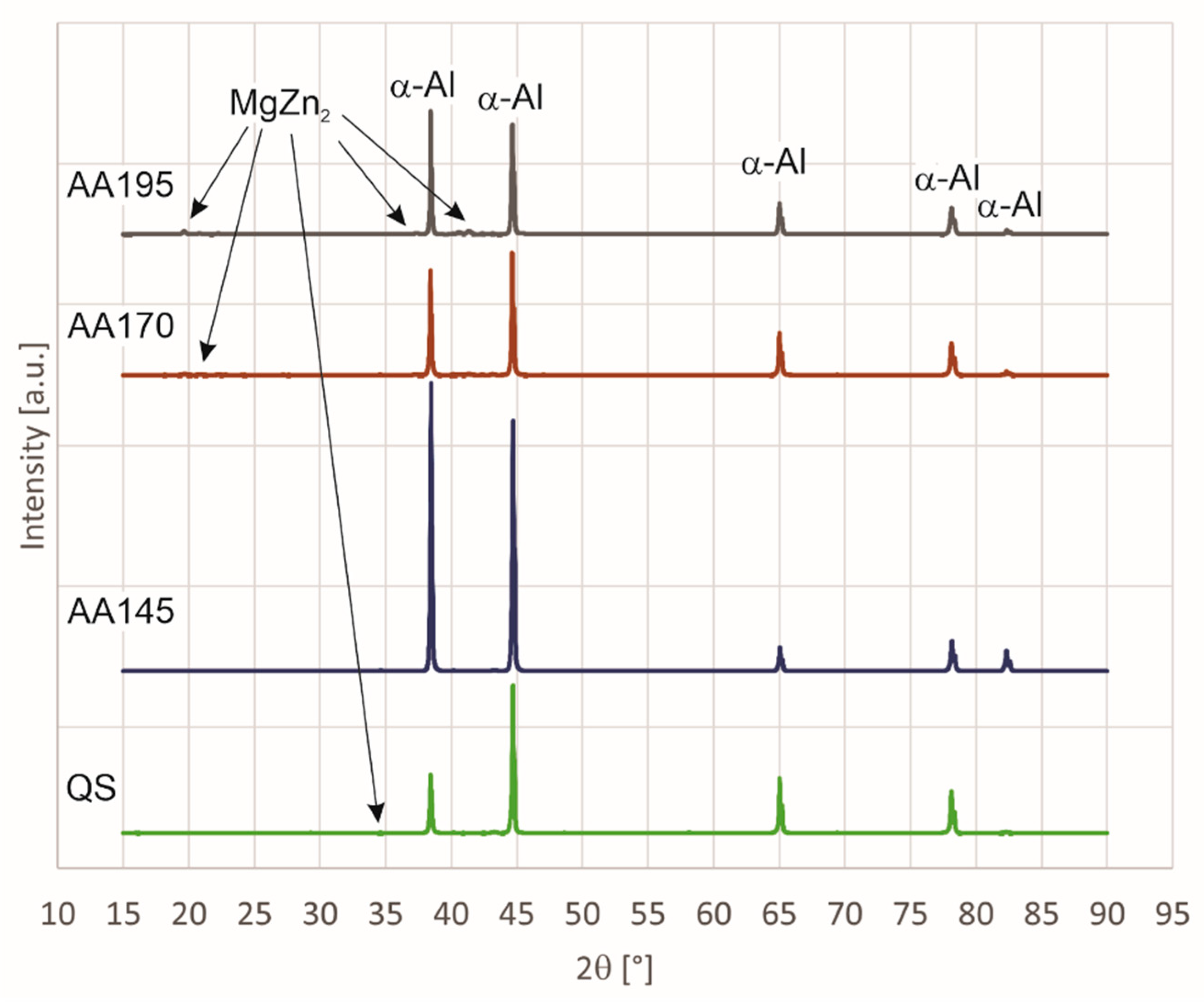
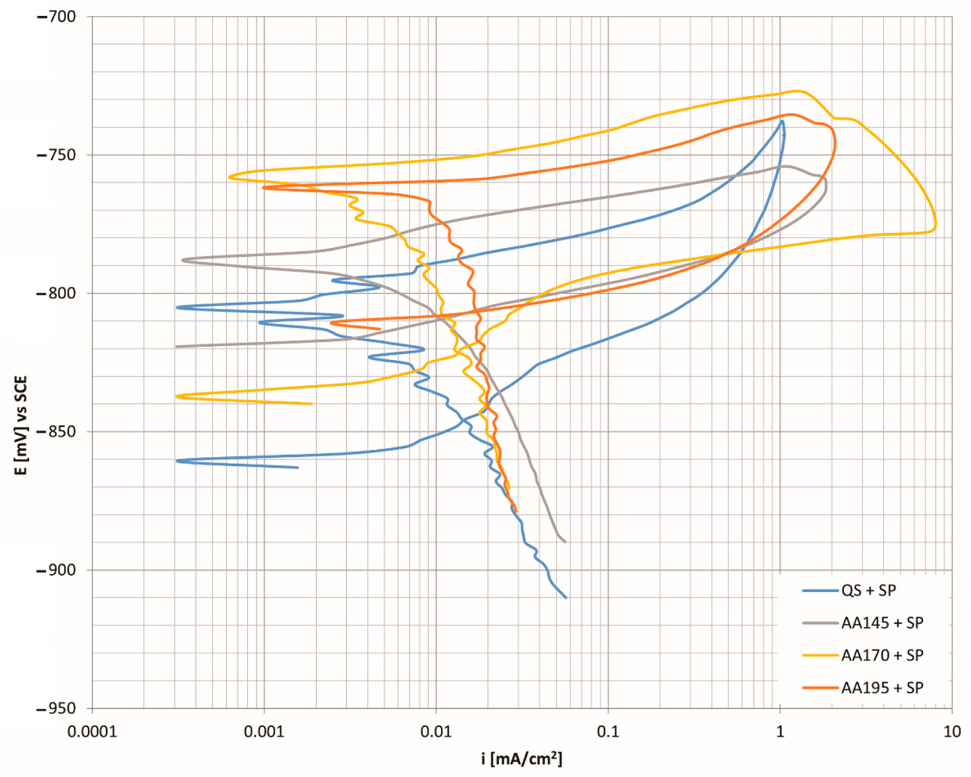
X-ray diffraction analysis of the surface shows the greatest difference in types of precipitates between the specimens in the quenched state and the specimens aged at 195 °C. Detailed analysis of the specimens shows that Al2CuMg precipitates dissolve in the specimen aged at 195 °C. If we connect this with corrosion resistance (Figure 7), we see that the specimen (AA195 + SP) has the highest corrosion current (icorr = 0.0117 μAcm−2), which also indicates the highest susceptibility to corrosion and the fastest degradation per year (C.R. = 127.4 μm/Y).
(b).
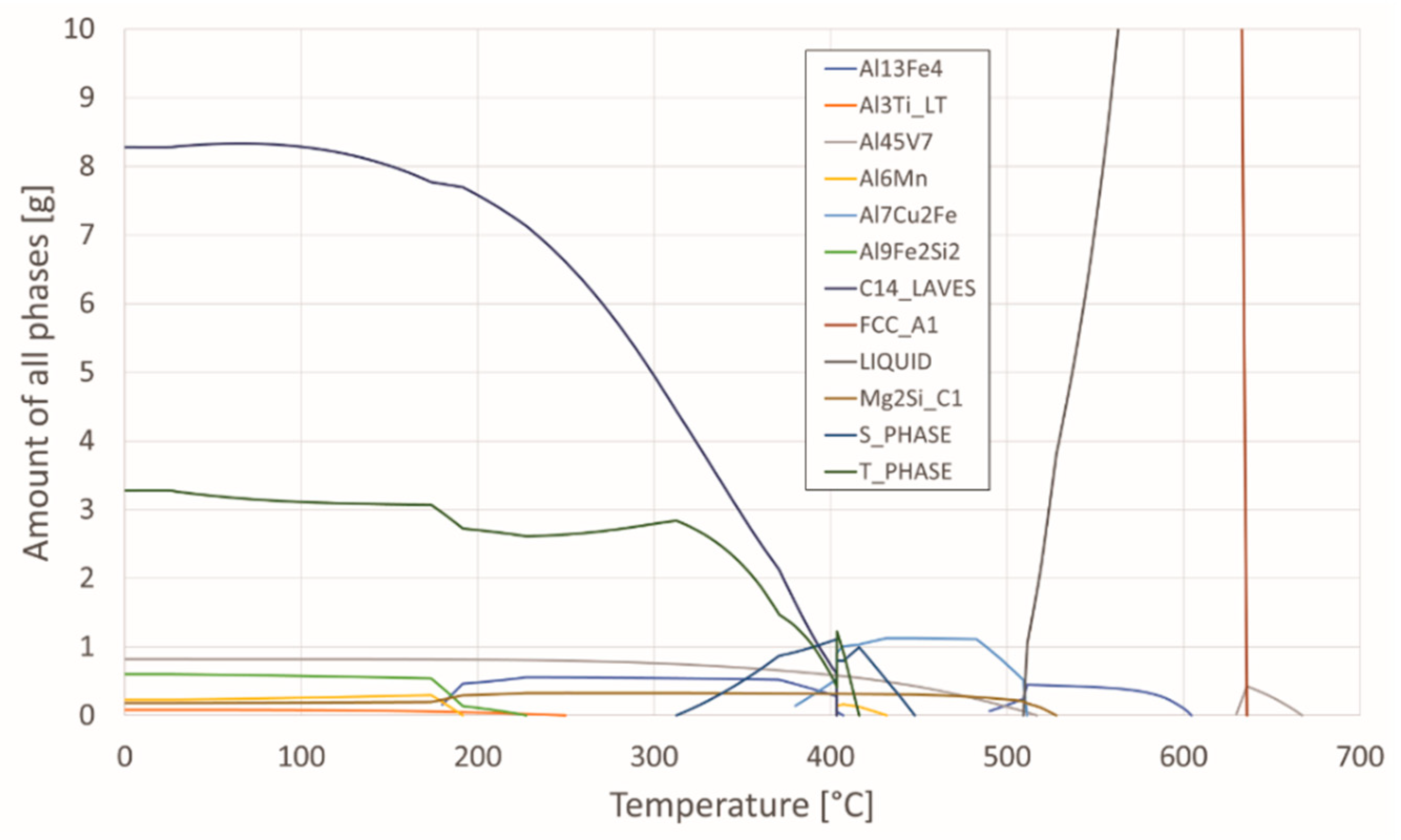
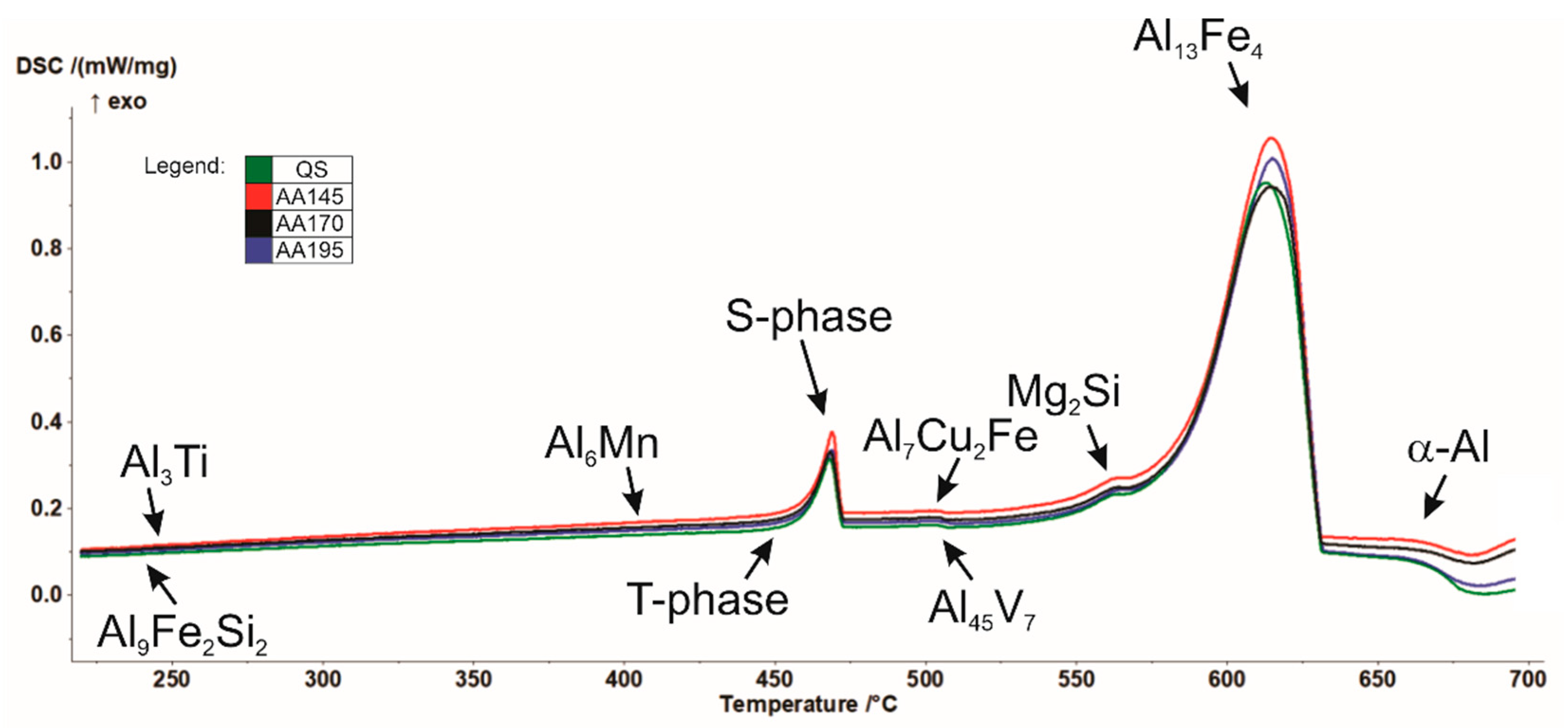
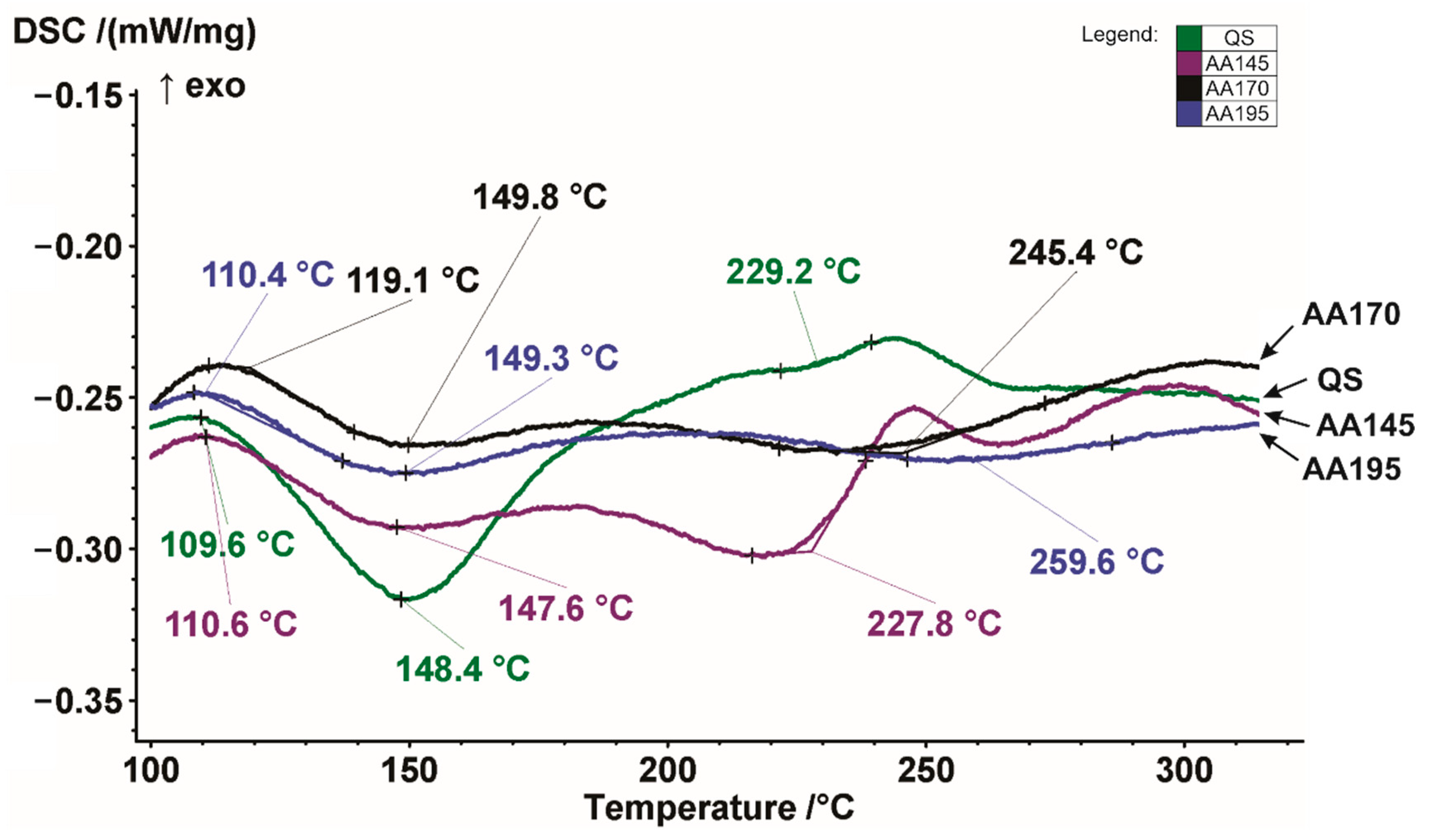
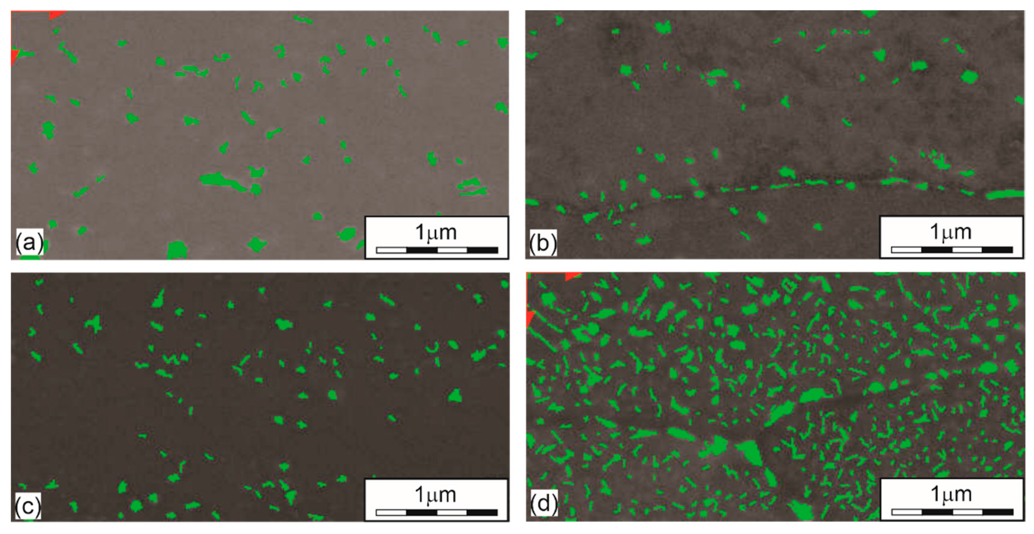
DSC analysis shows that solidification of the examined aluminium alloy begins with the growth of primary α-Al mixed crystals, followed by the crystallisation of the remaining melt into the intermetallic phase Al13Fe4, and finally, this is followed by the crystallisation of the phase η-MgZn2 phase. Again, most precipitates were found in the specimen (AA195 + SP) and because of that, corrosion resistance is the worst there as well. The number of precipitation phases is 5 times higher than in other specimens. The amount of precipitated phase indicates that the specimen was overaged.
(c).
After shot peening we achieve maximum hardness of the surface layer, when artificial ageing of aluminium alloy at 145 °C is selected. However, the corrosion resistance analysis shows that the minimum values of corrosion current and corrosion rate is obtained at a higher ageing temperature of 170 °C.
(d).
Cyclic polarisation curves of shot peened aluminium alloy with an Almen intensity 4A and 100% coverage shows that the most favourable results were obtained in the quenched and aged (at 170 °C) specimen. The volume share of precipitation phases is also about the same in these specimens, about 3.00%.
(e).
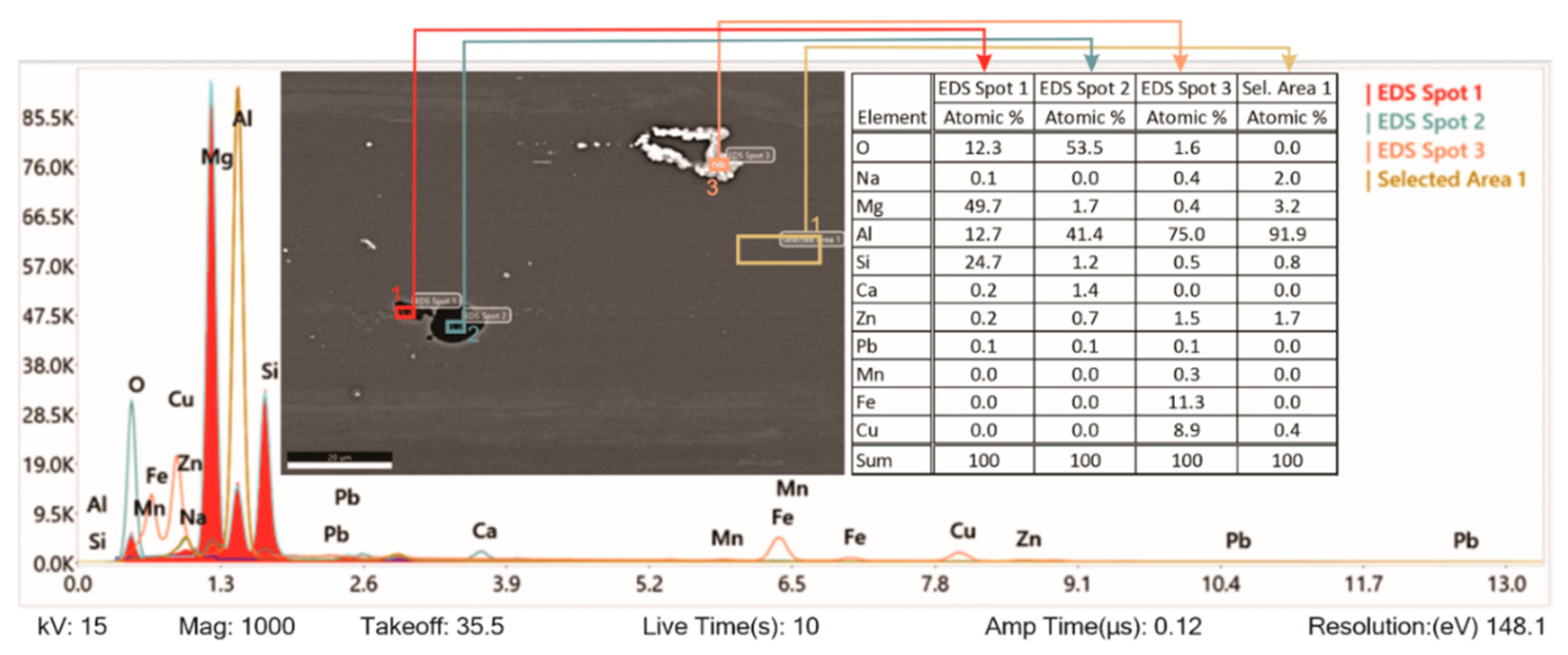
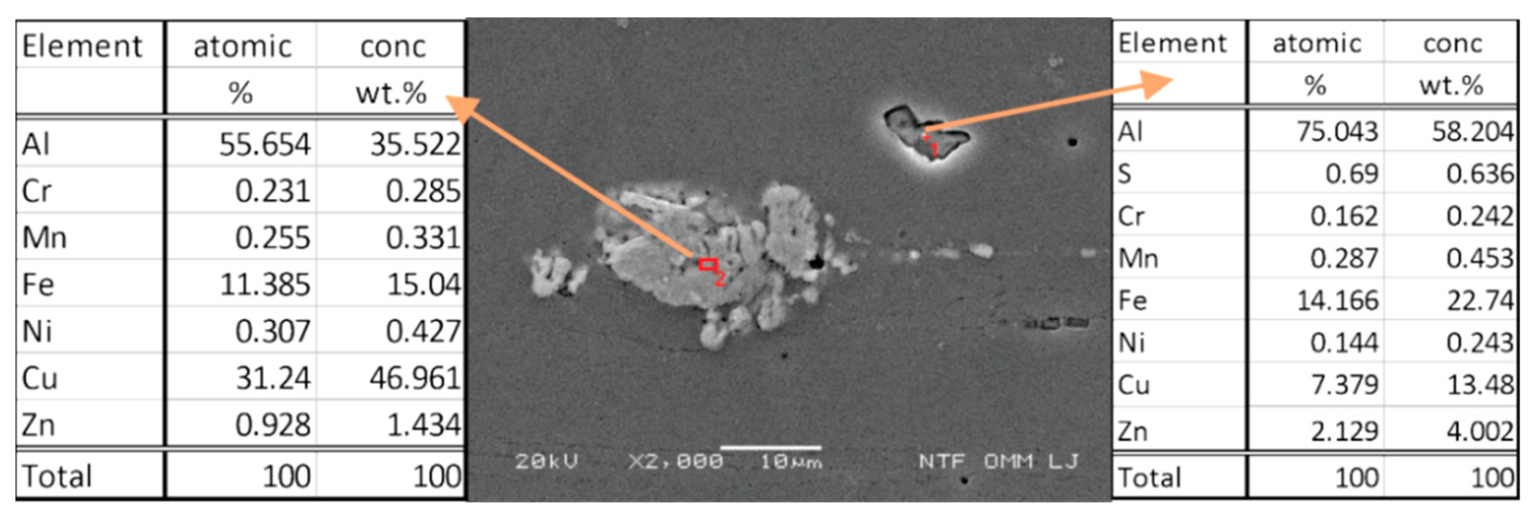
EDS analysis of the specimen surface shows higher contamination with chemical elements that are not present in our aluminium alloy. They were imprinted during the grinding process.

Author Contributions

Conceptualisation, S.Ž.; methodology, S.Ž. and R.Š.; investigation, S.Ž. and P.M.; preparation of the original written draft, S.Ž.; written review and editing, R.Š., J.G. and P.M. All authors have read and agreed to the published version of the manuscript.

Funding

This research received no external funding.

Institutional Review Board Statement

Not applicable.

Informed Consent Statement

Not applicable.

Data Availability Statement

Not applicable.

Acknowledgments

This work was partially funded by the Slovenian Research Agency (ARRS) under the research program P2-0270 Production systems, laser technologies and materials welding. Special thanks to Metal Improvement Company, Austria, for valuable technical assistance in selection of process parameters and application of shot peening treatment on all test specimens used in this work.

Conflicts of Interest

The authors declare that there are no conflict of interest.

References

  1. Schulze, V. Modern Mechanical Surface Treatment; WILEY-VCH GmbH &Co. KGaA: Weinheim, Germany, 2006. [Google Scholar]
  2. Wagner, L. Mechanical surface treatments on titanium, aluminum and magnesium alloys. Mater. Sci. Eng. A 1999, 263, 210–216. [Google Scholar] [CrossRef]
  3. Habibi, N.; H-Gangaraj, S.M.; Farrahi, G.H.; Majzoobi, G.H.; Mahmoudi, A.H.; Daghigh, M.; Yari, A.; Moridi, A. The effect of shot peening on fatigue life of welded tubular joint in offshore structure. Mater. Des. 2012, 36, 250–257. [Google Scholar] [CrossRef]
  4. Karademir, I.; Celik, M.B.; Husem, F.; Maleki, E.; Amanov, A.; Unal, O. Effects of constrained groove pressing, severe shot peening and ultrasonic nanocrystal surface modification on microstructure and mechanical behavior of S500MC high strength low alloy automotive steel. Appl. Surf. Sci. 2021, 538, 147935. [Google Scholar] [CrossRef]
  5. Luo, X.; Dang, N.; Wang, X. The effect of laser shock peening, shot peening and their combination on the microstructure and fatigue properties of Ti-6Al-4V titanium alloy. Int. J. Fatigue 2021, 153, 106465. [Google Scholar] [CrossRef]
  6. Tao, X.; Gao, Y. Effects of wet shot peening on microstructures and mechanical properties of a 2060-T8 aluminum-lithium alloy. Mater. Sci. Eng. A 2022, 832, 142436. [Google Scholar] [CrossRef]
  7. Wagner, L.; Mhaede, M.; Wollmann, M.; Altenberger, I.; Sano, Y. Surface layer properties and fatigue behavior in Al 7075-T73 and Ti-6Al-4V: Comparing Results after Shot Peening, Laser Shock Peening and Ball-Burnishing. Int. J. Struct. Integr. 2011, 2, 185–199. [Google Scholar] [CrossRef]
  8. Ohta, T.; Ma, N. Shot velocity measurement using particle image velocimetry and a numerical analysis of the residual stress in fine particle shot peening. J. Manuf. Processes 2020, 58, 1138–1149. [Google Scholar] [CrossRef]
  9. Rodopoulos, C.A.; Curtis, S.A.; Rios, E.R.; Solisromero, J. Optimisation of the Fatigue Resistance of 2024-T351 Aluminium Alloys by Controlled Shot Peening—Methodology, Results and Analysis. Int. J. Fatigue 2004, 26, 849–856. [Google Scholar] [CrossRef]
  10. Mhaede, M. Influence of surface treatments on surface layer properties, fatigue and corrosion fatigue performance of AA7075 T73. Mater. Des. 2012, 41, 61–66. [Google Scholar] [CrossRef]
  11. Champaigne, J. The Little Book on Shot Peening; Electronics Incorporated: Mishawaka, IN, USA, 2001. [Google Scholar]
  12. Zhou, B.; Liu, B.; Zhang, S.; Lin, R.; Jiang, Y.; Lan, X. Microstructure evolution of recycled 7075 aluminum alloy and its mechanical and corrosion properties. J. Alloys Compd. 2021, 879, 160407. [Google Scholar] [CrossRef]
  13. Bobby-Kannan, M.; Raja, V.S.; Raman, R. Influence of Multistep Aging on the Stress Corrosion Cracking Behavior of Aluminum Alloy 7010. Corros. J. 2003, 59, 881–889. [Google Scholar] [CrossRef]
  14. Mhaede, M.; Wollmann, M.; Wagner, L. Correlation between Mechanical Surface Treatments and Corrosion Behavior of Aluminum Alloys. In The European Corrosion Congress, EUROCORR2008; EUROCORR: Edinburgh, UK, 2008; p. 554. Available online: https://www.researchgate.net/publication/256136886_Correlation_between_Mechanical_Surface_Treatments_and_Corrosion_Behavior_of_Aluminum_Alloys (accessed on 22 February 2022).
  15. Prevéy, P.S.; Cammett, J.T. The influence of surface enhancement by low plasticity burnishing on the corrosion fatigue performance of AA7075-T6. Int. J. Fatigue 2004, 26, 975–982. [Google Scholar] [CrossRef]
  16. Padap, A.K.; Yadav, A.P.; Kumar, P.; Kumar, N. Effect of aging heat treatment and uniaxial compression on thermal behavior of 7075 aluminum alloy. Mater. Today Proc. 2020, 33, 5442–5447. [Google Scholar] [CrossRef]
  17. Du, Z.; Deng, Z.; Xiao, A.; Cui, X.; Yu, H.; Feng, Z. Effect of the aging process on the micro-structure & properties of 7075 aluminum alloy using electromagnetic bulging. J. Manuf. Processes 2021, 70, 15–23. [Google Scholar] [CrossRef]
  18. Carroll, M.C.; Gouma, P.I.; Mills, M.J.; Daehn, G.S.; Dunbar, B.R. Effects of Zn additions on the grain boundary precipitation and corrosion of Al-5083. Scr. Mater. 2008, 42, 335–340. [Google Scholar] [CrossRef]
  19. Oguocha, I.N.A.; Adigun, O.J.; Yannacopoulos, S. Effect of sensitization heat treatment on properties of Al–Mg alloy AA5083-H116. J. Mater. Sci. 2008, 43, 4208–4214. [Google Scholar] [CrossRef]
  20. Zhang, R.; Zhang, Y.; Yan, Y.; Thomas, S.; Davies, C.H.J.; Birbilis, N. The effect of reversion heat treatment on the degree of sensitisation for aluminium alloy AA5083. Corros. Sci. 2017, 126, 324–333. [Google Scholar] [CrossRef]
  21. Abdulstaar, M.; Mhaede, M.; Wollmann, M.; Wagner, L. Investigating the effects of bulk and surface severe plastic deformation on the fatigue, corrosion behaviour and corrosion fatigue of AA5083. Surf. Coat. Technol. 2014, 254, 244–251. [Google Scholar] [CrossRef]
  22. Ozdemira, F.; Witharamage, C.A.; Darwish, A.A.; Okuyucu, H.; Gupta, R.K. Corrosion behavior of age hardening aluminum alloys produced by high-energy ball milling. J. Alloys Compd. 2022, 900, 163488. [Google Scholar] [CrossRef]
  23. Amini, S.; Kariman, S.A.; Teimouri, R. The effects of ultrasonic peening on chemical corrosion behavior of aluminum 7075. Int. J. Adv. Manuf. Technol. 2017, 91, 1091–1102. [Google Scholar] [CrossRef]
  24. Pandey, V.; Singh, J.K.; Chattopadhyay, K.; Srinivas, N.C.S.; Singh, V. Influence of ultrasonic shot peening on corrosion behavior of 7075 aluminum alloy. J. Alloys Compd. 2017, 723, 826–840. [Google Scholar] [CrossRef]
  25. Safyari, M.; Moshtaghi, M. Role of Ultrasonic Shot Peening in Environmental Hydrogen Embrittlement Behavior of 7075-T6 Alloy. Hydrogen 2021, 2, 377–385. [Google Scholar] [CrossRef]
  26. Sun, Q.; Han, Q.; Wang, S.; Xu, R. Microstructure, corrosion behaviour and thermal stability of AA 7150 after ultrasonic shot peening. Surf. Coat. Technol. 2020, 398, 126127. [Google Scholar] [CrossRef]
  27. Ye, Z.; Liu, D.; Zhang, X.; Wu, Z.; Long, F. Influence of combined shot peening and PEO treatment on corrosion fatigue behavior of 7A85 aluminum alloy. Appl. Surf. Sci. 2019, 486, 72–79. [Google Scholar] [CrossRef]
  28. ASTM G5-14; Standard Reference Test Method for Making Potentiodynamic Anodic Polarization Measurements. ASTM International: West Conshohocken, PA, USA, 2014.
  29. Shahriyari, F.; Shaeri, M.H.; Bavarsiha, F.; Noghani, M.T. Creep behavior of solid solutioned and annealed Al-7075 alloy processed by equal channel angular pressing. Mater. Sci. Eng. A 2019, 765, 138225. [Google Scholar] [CrossRef]
  30. Lim, S.T.; Eun, I.S.; Nam, S.W. Control of Equilibrium Phases (M, T, S) in the Modified Aluminum Alloy 7175 for Thick Forging Applications. Mater. Trans. 2003, 44, 181–187. [Google Scholar] [CrossRef] [Green Version]
  31. Tekeli, S.; Simsek, I.; Simsek, D.; Ozyurek, D. Effects of Different Solid Solution Temperatures on Microstructure and Mechanical Properties of the AA7075 Alloy After T6 Heat Treatment. High Temp. Mater. Processes 2019, 38, 892–896. [Google Scholar] [CrossRef]
  32. Kilic, S.; Kacar, I.; Sahin, M.; Ozturk, F.; Erdem, O. Effects of Aging Temperature, Time, and Pre-Strain on Mechanical Properties of AA7075. Mater. Res. 2019, 22, 20190006. [Google Scholar] [CrossRef]
  33. Tsaknopoulos, K.; Sousa, B.; Massar, C.; Grubbs, J.; Siopis, M.; Cote, D. A Through-Process Experimental Approach to Enable Optimization of Cold Sprayed Al 7075 Consolidation Performance. JOM 2022, 74, 249–259. [Google Scholar] [CrossRef]
  34. Walde, C.; Tsaknopoulos, K.; Champagne, V.; Cote, D. Phase Transformations in Thermally Treated Gas-Atomized Al 7075 Powder. Metallogr. Microstruct. Anal. 2020, 9, 419–427. [Google Scholar] [CrossRef] [Green Version]
  35. Berg, L.K.; Gjønnes, J.; Hansen, V.; Li, X.Z.; Knutson-Wedel, M.; Waterloo, G.; Schryvers, D.; Wallenberg, L.R. GP-zones in Al–Zn–Mg alloys and their role in artificial aging. Acta Mater. 2001, 49, 3443–3451. [Google Scholar] [CrossRef]
  36. Luo, J.; Luo, H.; Li, S.; Wang, R.; Ma, Y. Effect of pre-ageing treatment on second nucleating of GPII zones and precipitation kinetics in an ultrafine grained 7075 aluminum alloy. Mater. Des. 2020, 187, 108402. [Google Scholar] [CrossRef]
  37. Gjønnes, J.; Simensen, C.J. An electron microscope investigation of the microstructure in aluminium–zinc–magnesium alloy. Acta Metall. 1970, 18, 881–890. [Google Scholar] [CrossRef]
  38. Jung, S.H.; Lee, J.; Kawasaki, M. Effects of Pre-Strain on the Aging Behavior of Al 7075 Alloy for Hot-Stamping Capability. Metals 2018, 8, 137. [Google Scholar] [CrossRef] [Green Version]
  39. Chemingui, M.; Ameur, R.; Optasanu, V.; Khitouni, M. DSC analysis of phase transformations during precipitation hardening in Al–Zn–Mg alloy (7020). J. Therm. Anal. Calorim. 2019, 136, 1887–1894. [Google Scholar] [CrossRef]
  40. Ku, M.H.; Hung, F.Y.; Lui, T.S.; Lai, J.J. Enhanced Formability and Accelerated Precipitation Behavior of 7075 Al Alloy Extruded Rod by High Temperature Aging. Metals 2018, 8, 648. [Google Scholar] [CrossRef] [Green Version]
  41. Wang, J.T.; Xie, L.; Wang, Z.G.; Gu, H.; Luo, K.Y.; Lu, Y.L.; He, M.T.; Ge, M.Z. Influence of laser shock peening on the coefficient of thermal expansion of Al (7075)-based hybrid composites. J. Alloys Compd. 2020, 844, 156088. [Google Scholar] [CrossRef]
  42. Takata, N.; Takagi, R.; Li, R.; Ishii, H.; Suzuki, A.; Kobashi, M. Precipitation morphology and kinetics of T-Al6Mg11Zn11 intermetallic phase in Al–Mg–Zn ternary alloys. Intermetallics 2021, 139, 107364. [Google Scholar] [CrossRef]
  43. Gopala Krishna, K.; Das, G.; Venkateswarlu, K.; Hari Kumar, K.C. Studies on Aging and Corrosion Properties of Cryorolled Al–Zn–Mg–Cu (AA7075) Alloy, Alloy. Trans. Indian Inst. Met. 2017, 70, 817–825. [Google Scholar] [CrossRef]
  44. Zuo, J.; Hou, L.; Shi, J.; Cui, H.; Zhuang, L.; Zhang, J. Effect of deformation induced precipitation on dynamic aging process and improvement of mechanical/corrosion properties AA7055 aluminum alloy. J. Alloys Compd. 2017, 708, 1131–1140. [Google Scholar] [CrossRef]
  45. Navaser, M.; Atapour, M. Effect of Friction Stir Processing on Pitting Corrosion and Intergranular Attack of 7075 Aluminum Alloy. J. Mater. Sci. Technol. 2017, 33, 155–165. [Google Scholar] [CrossRef]
  46. Fan, X.; Jiang, D.; Meng, Q.; Zhang, B.; Wang, T. Evolution of Eutectic Structures in Al-Zn-Mg-Cu Alloys During Heat Treatment. Trans. Nonferrous Met. Soc. China 2006, 16, 577–581. [Google Scholar] [CrossRef]
  47. Totten, G.E.; MacKenzie, D.S. Handbook of Aluminum: Vol. 1: Physical Metallurgy and Processes; Marcel Dekker, Inc.: New York, NY, USA, 2003. [Google Scholar]
  48. Ralston, K.D.; Fabijanic, D.; Birbilis, N. Effect of grain size on corrosion of high purity aluminium. Electrochim. Acta 2011, 56, 1729–1736. [Google Scholar] [CrossRef]
Figure 1. XRD diffraction patterns of AA7075 aluminium alloy subjected to various heat treatment conditions.
Materials 15 03094 g001
Figure 2. Proportion of phases as a function of temperature.
Materials 15 03094 g002
Figure 3. Cooling curves of the tested AA7075 specimens.
Materials 15 03094 g003
Figure 4. Detailed DSC heating curves of the examined AA7075 alloy in the quenched, and aged condition between 100 °C and 300 °C.
Materials 15 03094 g004
Figure 5. The amount of precipitated phases under different heat treatment conditions. (a) QS (3.63%); (b) T145 (2.93%); (c) T170 (3.05%); (d) T195 (15.16%).
Materials 15 03094 g005
Figure 6. CP curves as a function of the corrosion current density for the unhardened state at different age hardening temperatures.
Materials 15 03094 g006
Figure 7. CP curves as a function of corrosion current density for Almen intensity 4A and 100% coverage at different age hardening temperatures.
Materials 15 03094 g007
Figure 8. SEM image and EDS analysis of tested aluminium alloy.
Materials 15 03094 g008
Figure 9. SEM image and chemical analysis of precipitates.
Materials 15 03094 g009
Figure 10. SEM image and chemical analysis of precipitates.
Materials 15 03094 g010
Table 1. Chemical composition of the selected aluminium alloy (wt.%).
DesignationMgMnFeSiCuZnCrTiZr + TiAl
AA70752.360.050.170.121.585.700.190.03<0.01bal.
Table 2. Roughness and microhardness parameters of treated AA7075.
Alloy StateHV0.2
before SP
HV0.2
after SP
Ra
after SP
QS1551571.91
AA1451751852.02
AA1701601752.19
AA1951051182.53
Table 3. Reference temperatures of the onset of decomposition of the age-hardened phases.
Alloy StateExothermic Precipitation
Peaks [°C]
Endothermic Dissolution Peaks [°C]
1st2nd3rd4th1st2nd3rd
QS109.6220243/148.4//
AA145110.6182247296147.6216265
AA170119.1186304/149.8232/
AA195110.4210//149.3258/
Publisher’s Note: MDPI stays neutral with regard to jurisdictional claims in published maps and institutional affiliations.

