1. Introduction
There are many aspects to consider when constructing and designing any technical device. Designing machines and devices is based on finding innovative solutions that will make a given structure unique and different from others. However, it is necessary to follow certain construction principles, such as functionality, reliability, ergonomics, and efficiency. Each machine or device should also have a good value for its cost. In the case of warships, an essential factor is a mass above the centre of gravity [
1], and in the case of aircraft structures, mass is a general factor.
Currently, the world is looking for solutions to reduce the weight of ships. Numerical and technological methods allow for more accurate calculations, which translates into the thickness of the structural reinforcements. In contrast, modern technologies such as friction welding (FSW) [
2] translate into a reduction in the weight of joints. Another approach to weight reduction is using materials with higher specific strength, understood as the mechanical strength of a given material in relation to the specific weight [
3]. Aluminium–magnesium alloys can undoubtedly be used for the production of rivets. They can probably also be used in several other machine elements, especially where weight reduction is necessary for aviation and marine structures or underwater biomimetic vehicles [
4,
5]. Aluminium alloys have many advantages over steel: their density is 2.9 times lower, they do not rust in a marine environment, they are non-magnetic, and they conduct heat perfectly [
6].
Unlike in shipbuilding, riveting is still used to connect aircraft structures. This is due to the low mass of the connecting elements that constitute a significant aircraft mass, considering the economies of scale [
7].
One of the ideas for reducing the weight of aircraft structures is the use of alloys with increased strength for rivet materials. This will reduce their diameter and weight. Increased strength of aluminium alloys can be obtained using Severe Plastic Deformation (SPD) processes. Such methods include equal channel angular extrusion (ECAE) [
8], equal-channel angular hydro-extrusion (ECAH) [
9,
10], high-pressure torsion (HPT) [
11], accumulative roll bonding (ARB) [
12], repetitive corrugation and straightening (RCS) [
13], and asymmetric rolling (ASR) [
14].
2. Materials and Methods
In this study, we tested the aluminium–magnesium alloy Al7.5Mg (7.5% magnesium content) after the process of hydrostatic extrusion, with the degree of strengthening equal to
, intended for the production of rivets for aircraft structures. Hydro-extrusion is one of the many technologies of high plastic deformation, which enables controlled shaping of the microstructure, thus increasing the strength and plastic properties of the material. The degree of strengthening was calculated according to the formula [
8,
11,
15,
16,
17]:
where:
—initial bar diameter; and
—end bar diameter.
The aim of the work is to determine the material characteristics of Al7.5Mg alloys after hydro-extrusion for numerical calculations. The developed characteristics will then be used in FEM programs to determine the strength of riveted structures, such as aircraft plating. Aircraft structures work in challenging conditions. They are also exposed to impacts. At the design stage of an aircraft structure, it is necessary to perform several numerical tests and simulations, including fast-changing processes such as impact. Dynamic material characteristics depending on the strain rate are needed for these simulations. Before performing the FEM simulation, the characteristics of the material should be verified with simple laboratory experiments, which will allow determining their suitability.
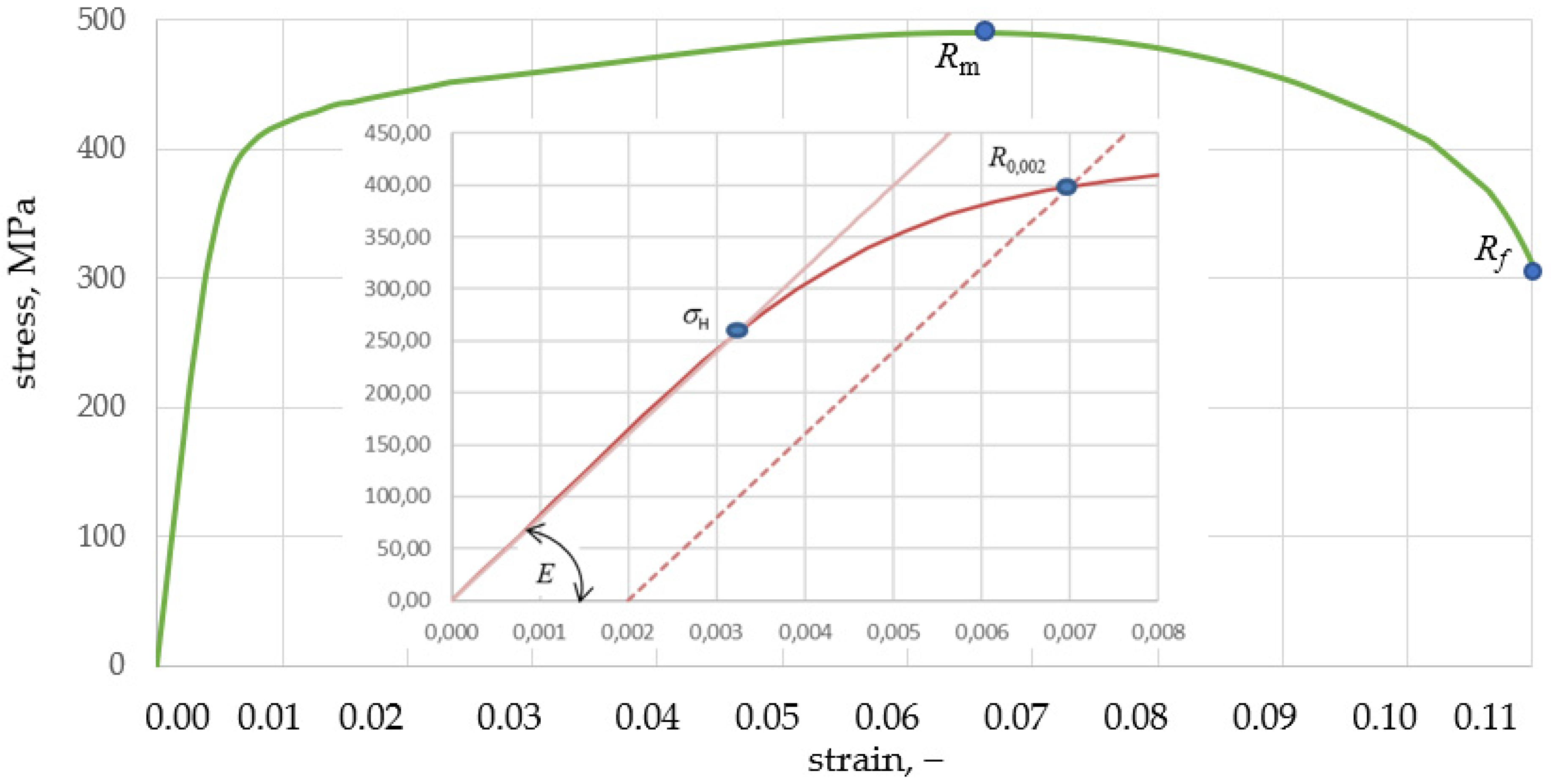
The static tensile test was carried out on the MTS testing machine, on which standard samples with a diameter of 8 mm were stretched in accordance with the EN ISO 6892-1: 2016 standard [
18]. The nominal characteristics, determined directly from the machine based on the tensile force and measurement from an extensometer with a working length of 40 mm, are shown in
Figure 1.
The nominal sizes are as follows:
Using the dependence between the true stresses
σtrue and nominal stresses
σnom, the volume of the stretched sample during stretching is constant, so:
Formulas (2)–(6) included in
Table 1 determine the true and plastic characteristics [
19].
Table 1 contains calculations for selected measuring points.
The Study of Dynamic Mechanical Properties Using a Rotary Hammer
The Fundamentals of Technology Laboratory of the Naval Academy in Gdynia has a unique stand, a rotary hammer (
Figure 2) that enables the dynamic tensile test at speeds in the range of 10 ÷ 50 m/s. A sample length of 20 mm allows the strain rate to be equal to 500 ÷ 2000 s
−1. In Poland, the Silesian University of Technology still has similar laboratory equipment [
20].
The rotary hammer station enables samples to be picked with a strain rate in the range of 0 ÷ 2000 s
−1. The rate of deformation can be determined from the formula [
21]:
Table 2 shows the results of sample breaking using a rotary hammer. The strain rates in the range of 535–2159 s
−1 were obtained, for which the values of the strength limit
Rm increase to over 631 MPa.
In CAE programs, functions
in the form of a polynomial are used to describe the plastic characteristic depending on the strain rate and temperature. The Johnson–Cook constitutive model is widely used in CAE programs [
22]. Given is a pattern:
where:
A—elastic range of the material (0.00002), it is often simplified in form A = Re;
B—hardening parameter;
n—hardening exponent;
C—strain rate coefficient;
—true plastic strain;
—strain rate;
– quasi-static strain rate (0.0001 s−1);
θ—current material temperature;
θ0—ambient temperature;
θmelt—melting temperature; and
m—thermal softening exponent.
Parameters
A, B, C, n, and
m can be determined in many ways [
21,
23,
24,
25] from the transformation of individual members of Equation (9). The results obtained from static and dynamic tests are substituted. We propose the following algorithm. From the nominal or real characteristic (in the proportionality range, both characteristics coincide), the coefficient A is determined: proportionality limit
for
0.00002.
In the first part of Equation (9), there are two unknown coefficients,
B and
n, constituting a dependent pair. From the transformation of the first term of Equation (9), we obtain:
The pair of coefficients
B and
n must satisfy Equation (9) at the point
Re,true and
Rm,true:
The C coefficient is determined from the second term of Equation (9) for a given strain rate (
Table 3).
The actual values of the strength limit are determined from Formula (6) (
Table 3).
The average value was assumed constant C = 0.018893. The characteristics of JC for selected strain rates are shown in
Figure 3.
The values for the temperature component can be taken based on the literature [
21,
26,
27]. They are similar for most steels, so:
Ambient temperature θ0 = 293.15 K;
Melting temperature θtop = 850 ÷ 855 K;
Thermal coefficient m = 1.3 ÷ 1.7.
3. The Failure Mechanism for AL7.5Mg
The material failure model used in CAE programs is detailed in the works [
21,
28,
29,
30,
31]. The value of the destructive deformation is a function of the so-called stress state indicator
ηTRIAX (stress triaxiality). It is the ratio of the pressure being the mean of the principal stresses to the Huber–Mises–Hencky (HMH) reduced stress
σHMH [
28,
29,
31].
where:
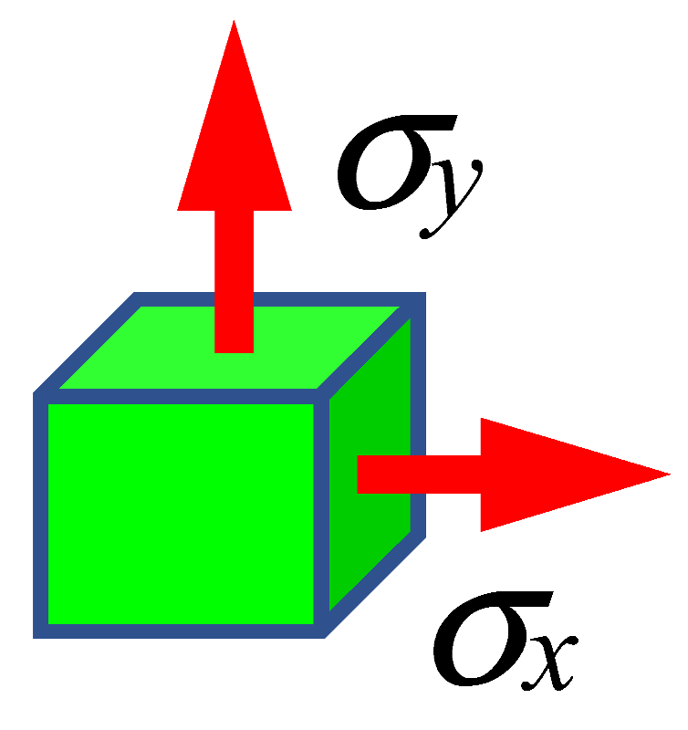
The triaxiality coefficient is an excellent identifier for the state of stress in complex states where it is difficult to discern whether an element is in compression, tension, bending, or twisting. For the uniaxial stretching state, the value of the triaxiality coefficient is equal to 0.33 (
Table 4).
The failure mechanism for AL7.5Mg is shown in
Figure 3, where 0–1 is the elastic range, 1–2 is the plastic range (hardening), and 2 is the initiation of the destruction process. Above 2, if the material model has no failure criteria, the stresses will vary to point 5 and beyond. If the load in point 2 disappears, the deformation will drop to point 7 along path 2–7 parallel to path 0–1. In the failure model, point 5 is above point 3 in curves 2–4. This is where strength (softening) is lost. The 2–4 degradation or failure curve is defined by parameter
d, which takes values from 0 to 1. The stress on the degradation curve is:
The material fracture occurs in point 4 after reaching the value of the fracture deformation
. However, if the element breaks or the forces loading the element disappear, e.g., in point 3 during the degradation of the material on the curve 2–4, then the remaining elastic forces will reduce its deformation to point 6 along the 3–6 path, which is not parallel to the 0–1 path. The evolution of failure determines the degree of degradation at which material failure will occur. The value
d = 0 means that the plastic stress has reached the value of
Rm, but the material has not yet been degraded, while the value
d = 1 means complete degradation of the material. The failure evolution is described as a function of the plastic displacement of the
upl, defined as [
33]:
where
L is the characteristic length of the FEM element.
The rate of evolution of failure describes the path along which material degradation develops. In CAE programs, linear, exponential, and tabular descriptions are adopted. The linear relationship is expressed as the ratio of plastic displacement to failure displacement:
Table 5 lists the points from the diagram in
Figure 3, based on which the failure parameters for tensile strength of Al7.5Mg were determined.
Following these parameters, calculations were carried out for uniaxial stretching:
Summarizing the tested Al7.5Mg can be described by the following equations:
Young’s modulus: GPa
Failure parameters:
; .
4. Material Data of the Elements of the Aircraft Structure
Rivets are the main research object in this work. For this reason, simplified bilinear material models were adopted for the remaining elements of the aircraft structure. The plating and reinforcement profile are made of the aluminium alloy 7075-T6 with the following mechanical properties:
Young’s modulus E = 71.7 GPa;
Yield stress R0.002 = 463 MPa;
Strength limit Rm = 530 MPa;
Poisson number ν = 0.33; and
Density ρ = 2810 kg/m3.
The material of the hammer and support is made of high-strength steel with the following mechanical properties:
Young’s modulus E = 2.09 × 10⁵ MPa;
Yield stress Re = 665 MPa;
Strength limit Rm = 776 MPa;
Poisson number ν = 0.33; and
Density ρ = 7850 kg/m3.
5. FEM Simulation of the Impact Strength of Riveted Aircraft Structure
The obtained model of the AL7.5Mg alloy should be verified. For this purpose, we performed a FEM simulation of the strength of the riveted aircraft structure, loaded with the impact of the drop hammer. The results of the FEM simulation were compared with the results of the same experiment.
5.1. Research Object, Its Geometry and Discretisation
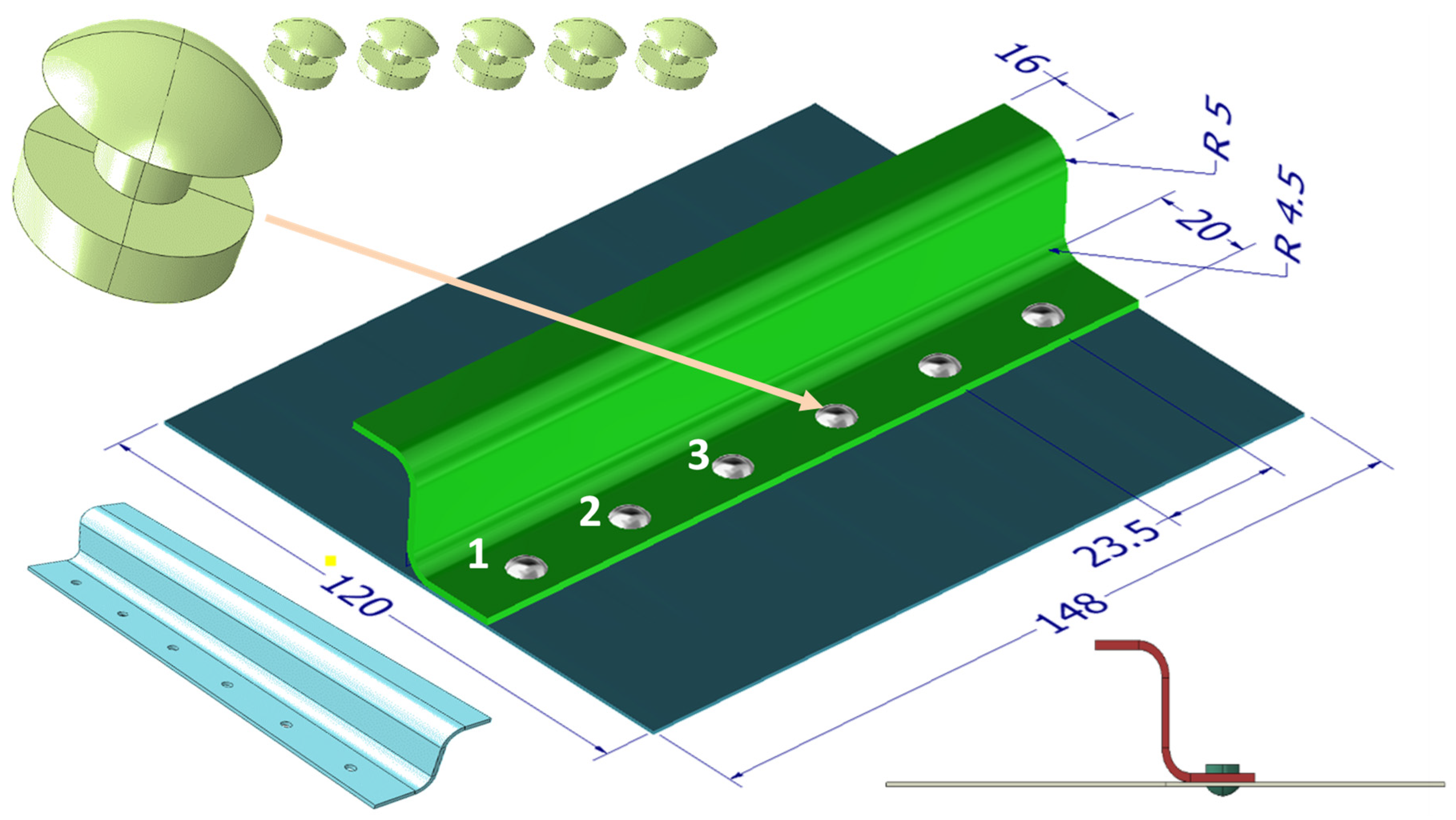
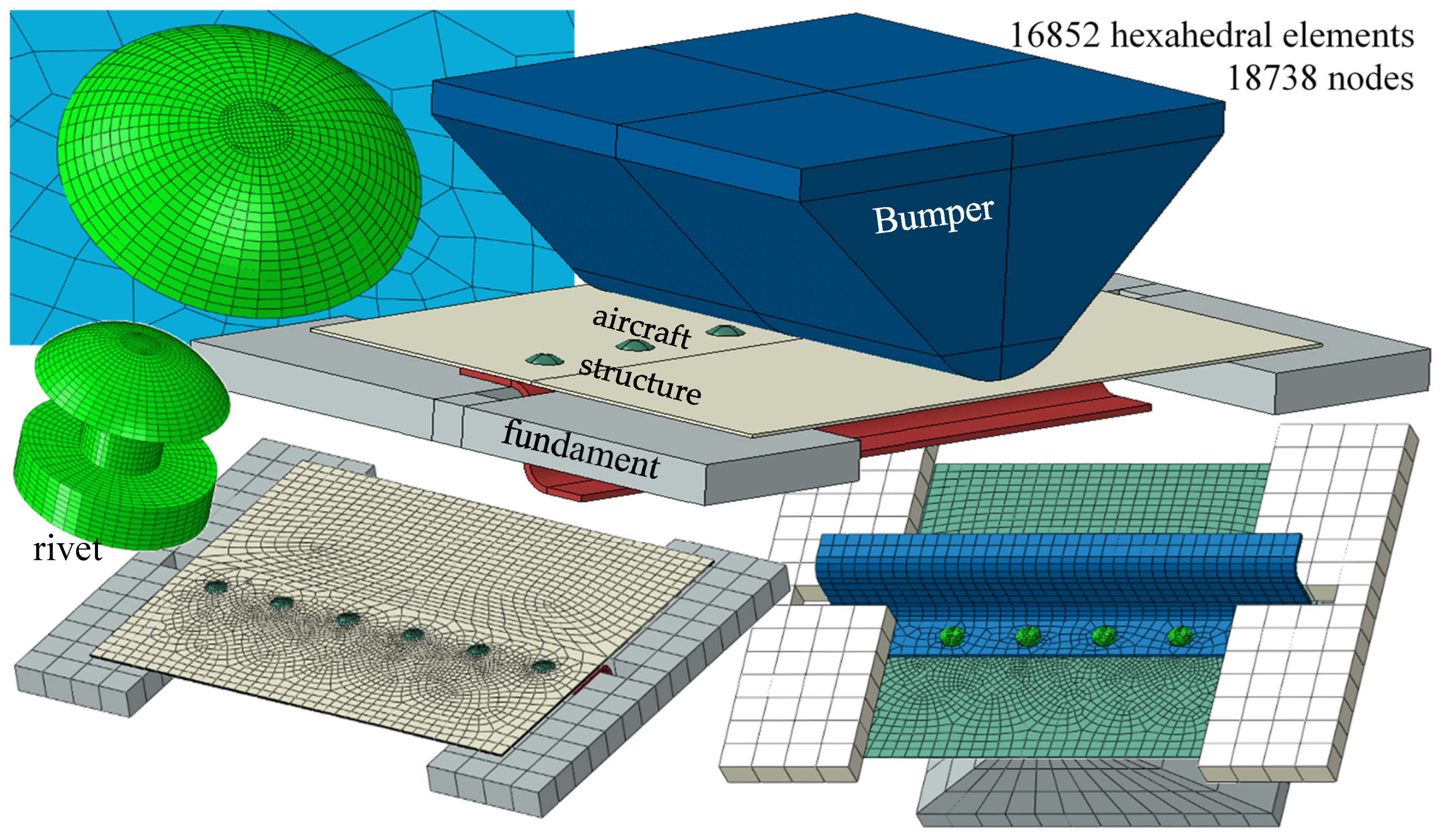
The test object is a fragment of the aircraft plating made of the 7075-T6 aluminium alloy with dimensions of 120 × 148 × 0.8 mm. It is connected with six rivets with a diameter of 3 mm with an S-shaped reinforcing profile with dimensions of 16 × 25 × 20 × 1.6 mm. The rivets are symmetrically spaced every 23.5 mm. The aluminium alloy Al7.5Mg after the hydro-extrusion process was proposed as a material for rivets. The geometry of these elements and the basic dimensions are shown in
Figure 4. A fragment of the aircraft structure will be subjected to the impact of the drop hammer.
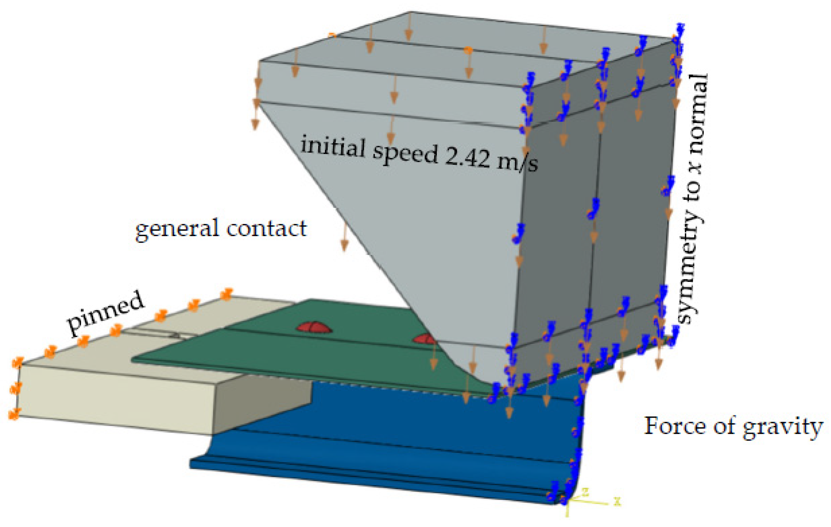
In the Fundamentals of Technology Laboratory of the Naval Academy (AMW) in Gdynia (Poland), an experiment was conducted on an identical object loaded with a drop bumper. The aircraft structure was hit by a 35.81 kg bumper falling from a height of 30 cm to its flat side (
Figure 5). At the moment of impact (contact), the bumper reached a speed of 2.42 m/s.
The geometry of individual elements of the aircraft structure was reflected in the CAD program, where it was also assembled into a set (
Figure 6). It was exported to the CAE program, where steel supports and a bumper were reflected. The entire structure with supports and a hammer was discretised by 124,643 linear eight-node hexagonal elements delimited in space by 140,899 nodes, giving 845,394 degrees of freedom (
Figure 6). Each rivet was divided into 16,852 elements delimited in space by 18,738 nodes. The size of the rivet mesh is
L = 0.2 mm.
5.2. Boundary Conditions and Loads
The following boundary conditions were assumed: all displacements were suspended on opposite surfaces with a rectangular base on which the sample rests. The hammer was given an initial velocity at the moment of impact of 2.42 m/s and made to ensure vertical movement. In addition, all elements were mass-loaded with the acceleration due to gravity of 9.81 m/s, which is a gravitational load. All individual parts were given “general contact” interactions in the assembly, i.e., mutual interactions between all elements. The symmetry of the task was used, and half of the structure was solved. Displacements in the perpendicular direction and rotations in planes perpendicular to the plane of symmetry were obtained from all nodes lying on the plane of symmetry (
Figure 7).
5.3. Equation of Motion
Due to the impact nature of the load, material nonlinearities, and interactions between structural elements, the FEM dynamic equation of motion (dynamic explicit analysis) was solved using the Newmark numerical integration method in the form of:
where:
K—structure stiffness matrix;
M—inertia matrix;
—damping matrix, where α and β are constant coefficients;
—vector of displacement, velocity and acceleration;
, —initial conditions, displacements and velocities;
F—vector of loads;
—strain rate;
—vector of plastic strains (JC model);
—failure parameters ,;
—hammer speed;
—the mass of the bumper;
BC—the influence of boundary conditions;
Cint—interactions and contact forces between colliding structural elements; and
G—the force of gravity
5.4. The Time Step
One of the problems in the numerical integration of motion equations is selecting the appropriate time step, which depends on the structure elements’ elasticity modulus and material density [
35]. The time step value is the ratio of the smallest size in single-element mesh to the speed of the elastic (acoustic) wave propagation in the element material, i.e.,
where:
h—the smallest size of single element mesh; and
—elastic (acoustic) wave velocity.
For aluminium, the speed of sound is approximately 5100 m/s. In the aircraft structure, the smallest size in the mesh of finite elements has rivets h = 0.2 mm, so the required time step must be less than 3.92 × 10⁻⁸ s.
6. FEM Simulation Results—Rivets Made of Al7.5Mg Alloy
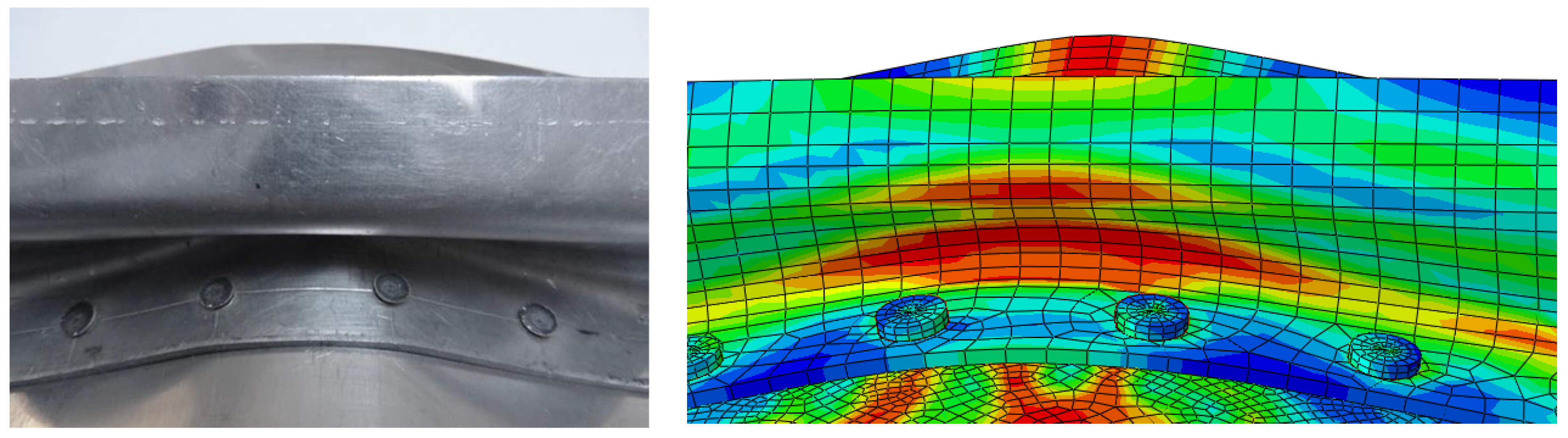
Only selected results are presented, mainly the HMH reduced stresses (
Figure 8). The focus is on stresses in rivets, as they are of extreme value. The stresses of the HMH exceed the limits of their strength and break as a result. The form of deformation is similar to the results of the experiment (
Figure 9).
Figure 10 shows the shape of the aircraft structure after impact and in rivets.
Figure 11 and
Figure 12 show the development of deformation and the HMH reduced stress state in the extreme rivets.
Figure 13 shows the failure criterion in extreme rivets at selected time moments. Already in 3 ms, it reaches the value of 1 in several finite elements and develops into the following elements, covering the entire rivet core in 20 ms.
In the rivet elements, the average strain rates oscillate within the limits of 0–2000 s
−1, temporarily reaching the values of 5000 s
−1, while locally, in the broken elements, the strain rates reach a value of up to 43,700 s
−1 (
Figure 14).
7. Discussion
The simulation results for a fragment of the aircraft structure were compared with the experiment results. Satisfying compliance of the deformation state after impact was obtained. This confirms the correctness of the modelled task and description of the tested material, the AL7.5Mg alloy after hydro-extrusion.
The extreme rivets were broken, but it should be noted that a fragment of the structure was analysed. The rivets will probably not fail in the continuous plating, with an impact of similar parameters, but the structure is likely to become unsealed. The internal rivets withstand the set load due to aluminium’s relatively high strength limit and high plasticity. The static strength limit is 523 MPa, and at deformation rates over 500 s−1, it increases over 670 MPa. With rivets of larger diameter, they will not break.
In this paper, the material characteristics of the tested material were developed for uniaxial stretching. The triaxiality coefficient identifies the plastic failure depending on the stress state, the value of which is 1/3, and for uniaxial compression, the value is 1/3. Other values of the triaxiality factor can be obtained by stretching the sample with a notch. The shape of the notch changes the direction of the forces, which was shown in the works [
36,
37,
38], which investigated samples with a notch. In these studies, the triaxiality coefficient determined by the Bridgman equation [
15] was used to identify the direction of the forces:
where (
Figure 15):
r—radius of the smallest cross-sectional area, mm; and
R—notch radius, mm.
The tests of the Al7.5Mg aluminium alloy will be continued in order to complete the material characteristics for the remaining values of the triaxiality coefficient, which will be the subject of the next article.
The characteristics of the Al7.5Mg alloy presented here and verified can be used to simulate much more complex structures and objects, which requires appropriate computing power. The presented task was calculated on an 8-core PC (i7—2.80 GHz) and lasted about 20 h.
8. Conclusions
Strength tests carried out in the laboratory allowed us to determine the mechanical properties of the AL7.5Mg alloy after hydro-extrusion in the deformation speed range of 0–2000 s−1. The following results were obtained: yield strength Re = 395.3 MPa; strength limit Rm = 523.1 MPa at deformation 0.067; Young’s modulus E = 7.9 × 10⁴ MPa. The AL7.5Mg alloy after hydro-extrusion has favourable plastic and strength properties.
Based on the above research, a constitutive model of Johnson–Cook AL7.5Mg was developed, which is ready for use in CAE programs.
The increase in the strain rate above 2000 s−1 increases the strength of the tested alloy to 690 MPa.
The failure parameters for tensile strength (
η = 0.33) were determined. The same parameters were adopted for compression for
η = −0.33. Failure parameters:
;
. For the remaining values of the
η coefficient, tensile tests of the notched samples should be carried out using the Bridgman equation [
15].
The use of rivets made of Al7.5Mg alloys subjected to SPD processes may contribute to the reduction in the cross-sectional area of the joints of aircraft structures. This will reduce the weight of the aircraft.
The presented characteristics constitute a ready-made solution to be implemented in CAE programs. They do not deal with the influence of machining on mechanical properties, but represent an engineering solution for implementation in calculations related to the use of Al7.5Mg alloys.
The correctness of the task can be verified only by an actual experiment. When designing individual objects, e.g., ships and vehicles, so-called crash tests are impossible or too expensive in many cases. FEM simulations are the only source of information about the behaviour of the structure under dynamic loads.
Author Contributions
Conceptualisation, B.S.; methodology, B.S.; software: B.S., R.K.; validation, B.S., R.K.; formal analysis, B.S., R.K.; investigation, B.S., R.K.; resources, B.S.; data curation, B.S.; writing—original draft preparation, B.S.; writing—review and editing, B.S., R.K.; visualisation B.S., R.K.; supervision, B.S.; project administration, B.S.; funding acquisition, B.S. All authors have read and agreed to the published version of the manuscript.
Funding
This research received no external funding.
Data Availability Statement
Not applicable.
Conflicts of Interest
The authors declare no conflict of interest.
References
- Kiciński, R.; Kubit, A. Small Caliber Bulletproof Test of Warships’ Hulls. Materials 2020, 13, 3848. [Google Scholar] [CrossRef] [PubMed]
- Mortello, M.; Pedemonte, M.; Contuzzi, N.; Casalino, G. Experimental Investigation of Material Properties in FSW Dissimilar Aluminum-Steel Lap Joints. Metals 2021, 11, 1474. [Google Scholar] [CrossRef]
- Koniuszewska, A.; Naplocha, K.; Kaczmar, J.W. Zastosowanie lekkich elementów z kompozytów polimerowych i metalowych w budowie środków transportu. TTS Tech. Transp. Szyn. 2015, 22, 12. [Google Scholar]
- Piskur, P.; Szymak, P.; Przybylski, M.; Naus, K.; Jaskólski, K.; Żokowski, M. Innovative Energy-Saving Propulsion System for Low-Speed Biomimetic Underwater Vehicles. Energies 2021, 14, 8418. [Google Scholar] [CrossRef]
- Piskur, P.; Szymak, P.; Kitowski, Z.; Flis, L. Influence of Fin’s Material Capabilities on the Propulsion System of Biomimetic Underwater Vehicle. Pol. Marit. Res. 2020, 27, 179–185. [Google Scholar] [CrossRef]
- Szala, M.; Łatka, L.; Walczak, M.; Winnicki, M. Comparative Study on the Cavitation Erosion and Sliding Wear of Cold-Sprayed Al/Al2O3 and Cu/Al2O3 Coatings, and Stainless Steel, Aluminium Alloy, Copper and Brass. Metals 2020, 10, 856. [Google Scholar] [CrossRef]
- Sęp, J. Połączenia stosowane w konstrukcjach lotniczych. Kierunki doskonalenia technologii. Stal Met. Nowe Technol. 2014, 9–10, 128–133. [Google Scholar]
- Segal, V. Equal-Channel Angular Extrusion (ECAE): From a Laboratory Curiosity to an Industrial Technology. Metals 2020, 10, 244. [Google Scholar] [CrossRef] [Green Version]
- Spuskanyuk, V.; Spuskanyuk, A.; Varyukhin, V. Development of the Equal-Channel Angular Hydroextrusion. J. Mater. Process. Technol. 2008, 203, 305–309. [Google Scholar] [CrossRef]
- Jurczak, W.; Trzepieciński, T.; Kubit, A.; Bochnowski, W. Static and Dynamic Properties of Al-Mg Alloys Subjected to Hydrostatic Extrusion. Materials 2022, 15, 1066. [Google Scholar] [CrossRef]
- Bridgman, P.W. Flow Phenomena in Heavily Stressed Metals. J. Appl. Phys. 1937, 8, 328–336. [Google Scholar] [CrossRef]
- Saito, Y.; Utsunomiya, H.; Tsuji, N.; Sakai, T. Novel Ultra-High Straining Process for Bulk Materials—Development of the Accumulative Roll-Bonding (ARB) Process. Acta Mater. 1999, 47, 579–583. [Google Scholar] [CrossRef]
- Mirsepasi, A.; Nili-Ahmadabadi, M.; Habibi-Parsa, M.; Ghasemi-Nanesa, H.; Dizaji, A.F. Microstructure and Mechanical Behavior of Martensitic Steel Severely Deformed by the Novel Technique of Repetitive Corrugation and Straightening by Rolling. Mater. Sci. Eng. A 2012, 551, 32–39. [Google Scholar] [CrossRef]
- Cui, Q.; Ohori, K. Grain Refinement of High Purity Aluminium by Asymmetric Rolling. Mater. Sci. Technol. 2000, 16, 1095–1101. [Google Scholar] [CrossRef]
- Bridgman, P.W. Studies in Large Plastic Flow and Fracture with Special Emphasis on the Effects of Hydrostatic Pressure; McGraw-Hill: New York, NY, USA, 1952. [Google Scholar]
- Segal, V. Review: Modes and Processes of Severe Plastic Deformation (SPD). Materials 2018, 11, 1175. [Google Scholar] [CrossRef] [PubMed] [Green Version]
- Lewandowska, M. Kształtowanie mikrostruktury i właściwości stopów aluminium metodą wyciskania hydrostatycznego. Pr. Nauk. Politech. Warszawskiej. Inżynieria Mater. 2006, 19, 3–90. [Google Scholar]
- Polish Norm PN-EN ISO 6892-1:2016; Metallic Materials. Tensile Testing. Part 1—Method of Test at Room Temperature. ISO: London, UK, 2016.
- Szturomski, B. Inżynierskie Zastosowanie MES w Problemach Mechaniki Ciała Stałego Na Przykładzie Programu ABAQUS [Engineering Application of FEM in Problems of Solid Mechanics on the Example of the ABAQUS Program—Available in Polish]; Wydawnictwo Akademickie AMW: Gdynia, Poland, 2013. [Google Scholar]
- Pawlicki, J.; Rodak, K.; Płachta, A. Plastyczność wybranych materiałów metalicznych w warunkach dynamicznego odkształcania. Zesz. Nauk. Transp./Politech. Śląska 2014, 83, 173–182. [Google Scholar]
- Szturomski, B. Modelowanie Oddziaływania Wybuchu Podwodnego Na Kadłub Okrętu w Ujęciu Numerycznym [Modeling the Effect of the Underwater Explosion to Hull Board in a Numberic Concept—In Polish]; Akademia Marynarki Wojennej: Gdynia, Poland, 2016. [Google Scholar]
- Johnson, G.R.; Cook, W.H. Fracture Characteristics of Three Metals Subjected to Various Strains, Strain Rates, Temperatures and Pressures. Eng. Fract. Mech. 1985, 21, 31–48. [Google Scholar] [CrossRef]
- Flis, L. Identyfikacja Parametrów Równania Konstytutywnego Johnsona-Cook’a w Odniesieniu Do Symulacji MES [Identification of Parameters of the Johnson-Cook Constitutive Equation for FEM Simulation—in Polish]. In Proceedings of the XIII Konferencji n.t. Techniki Komputerowe w Inżynierii 2014, Stary Licheń, Polska, 6–9 May 2014. [Google Scholar]
- Szturomski, B.; Kiciński, R. Material Properties of HY 80 Steel after 55 Years of Operation for FEM Applications. Materials 2021, 14, 4213. [Google Scholar] [CrossRef]
- Szturomski, B. Dynamic Characteristics of High Quality Steel in Johnson-Cook’s Model for Fast Processes Simulation in CAE Programs. Solid State Phenom. 2015, 236, 31–38. [Google Scholar] [CrossRef]
- Hiermaier, S. Structures under Crash and Impact; Springer: Berlin, Germany, 2008. [Google Scholar]
- Jaspers, S.P.F.C.; Dautzenberg, J.H. Material Behaviour in Conditions Similar to Metal Cutting: Flow Stress in the Primary Shear Zone. J. Mater. Processing Technol. 2002, 122, 322–330. [Google Scholar] [CrossRef]
- Abaqus 6.14 Theory Manual; Simulia, Dassault Systems: Paris, France, 2014.
- ANSYS: 5.5. Theory Reference Manual. In Elements Reference Manua, 8th ed.; Kohnke, P., Ed.; ANSYS, Inc.: Canonsburg, PA, USA, 1998. [Google Scholar]
- Banerjee, A.; Dhar, S.; Acharyya, S.; Datta, D.; Nayak, N. Determination of Johnson Cook Material and Failure Model Constants and Numerical Modelling of Charpy Impact Test of Armour Steel. Mater. Sci. Eng. A 2015, 640, 200–209. [Google Scholar] [CrossRef]
- Bao, Y.; Wierzbicki, T. On Fracture Locus in the Equivalent Strain and Stress Triaxiality Space. Int. J. Mech. Sci. 2004, 46, 81–98. [Google Scholar] [CrossRef]
- Kut, S. State of stress identification in numerical modeling of 3D issues. Arch. Metall. Mater. 2009, 54, 627–632. [Google Scholar]
- Bathe, K.J.; Wilson, E.L. Numerical Methods in Finite Element Analysis; Prentice-Hall: Englewood Cliffs, NJ, USA, 1976. [Google Scholar]
- Kubit, A.; Jurczak, W.; Trzepiecinski, T.; Faes, K. Experimental and Numerical Investigation of Impact Resistance of Riveted and RFSSW Stringer-Stiffened Panels in Blunt Impact Tests. Trans. FAMENA 2020, 44, 47–58. [Google Scholar] [CrossRef]
- Dobrociński, S. Stability of Solutions to the Problems of Impact Resistance of Structures, (in Polish, Stabilność Rozwiązań Zagadnień Odporności Udarowej Konstrukcji); Akademia Marynarki Wojennej: Gdynia, Poland, 2000. [Google Scholar]
- Bao, Y.; Wierzbicki, T.A. A Comparive Study on Various Ductile Crack Formation Criteria. J. Eng. Mater. Technol. 2004, 126, 314–324. [Google Scholar] [CrossRef]
- Hancock, J.W.; Mackenzie, A.C. On the Mechanisms of Ductile Failure in High-Strength Steels Subjected to Multi-Axial Stress-States. J. Mech. Phys. Solids 1976, 24, 147–160. [Google Scholar] [CrossRef]
- Tao, L. Fracture Strain of Gun Steel for Ultra-High-Pressure Vessels Considering Triaxiality Effect. Adv. Mech. Eng. 2017, 9, 1687814017714977. [Google Scholar] [CrossRef] [Green Version]
Figure 1.
Nominal characteristics of the Al7.5Mg aluminium alloy after hydro-extrusion.
Figure 1.
Nominal characteristics of the Al7.5Mg aluminium alloy after hydro-extrusion.
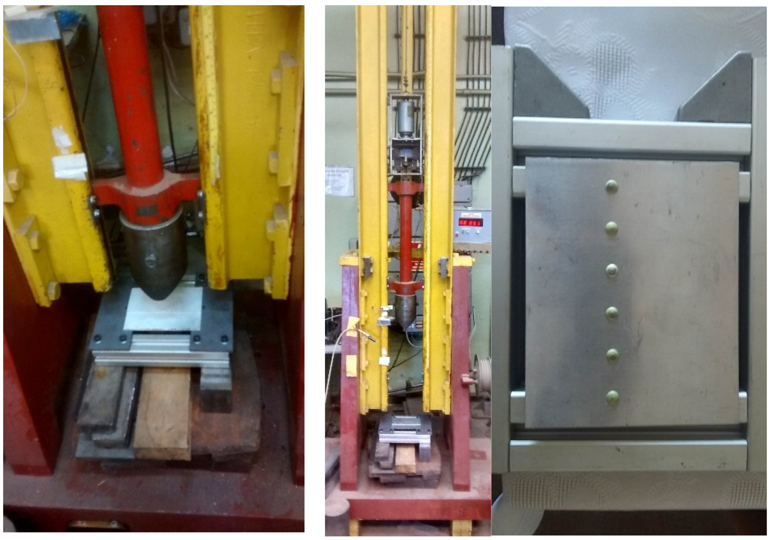
Figure 2.
Rotary hammer station (Fundamentals of Technology Laboratory, Polish Naval Academy) and scheme of dynamic tensile test on a rotary hammer.
Figure 2.
Rotary hammer station (Fundamentals of Technology Laboratory, Polish Naval Academy) and scheme of dynamic tensile test on a rotary hammer.
Figure 3.
Failure diagram of the true characteristics of Al7.5Mg (σtrue− εtrue).
Figure 3.
Failure diagram of the true characteristics of Al7.5Mg (σtrue− εtrue).
Figure 4.
The geometry of the test object, the numbering of rivets [
34].
Figure 4.
The geometry of the test object, the numbering of rivets [
34].
Figure 5.
The course of the experiment on the drop hammer at the Polish Naval Academy. From left: drop hammer station in the laboratory; view of the bumper and aircraft structure; view of the aircraft structure from the impact side; bumper at the moment of impact.
Figure 5.
The course of the experiment on the drop hammer at the Polish Naval Academy. From left: drop hammer station in the laboratory; view of the bumper and aircraft structure; view of the aircraft structure from the impact side; bumper at the moment of impact.
Figure 6.
Geometry and discretisation of aircraft structure elements in the CAE program.
Figure 6.
Geometry and discretisation of aircraft structure elements in the CAE program.
Figure 7.
Boundary conditions and loads.
Figure 7.
Boundary conditions and loads.
Figure 8.
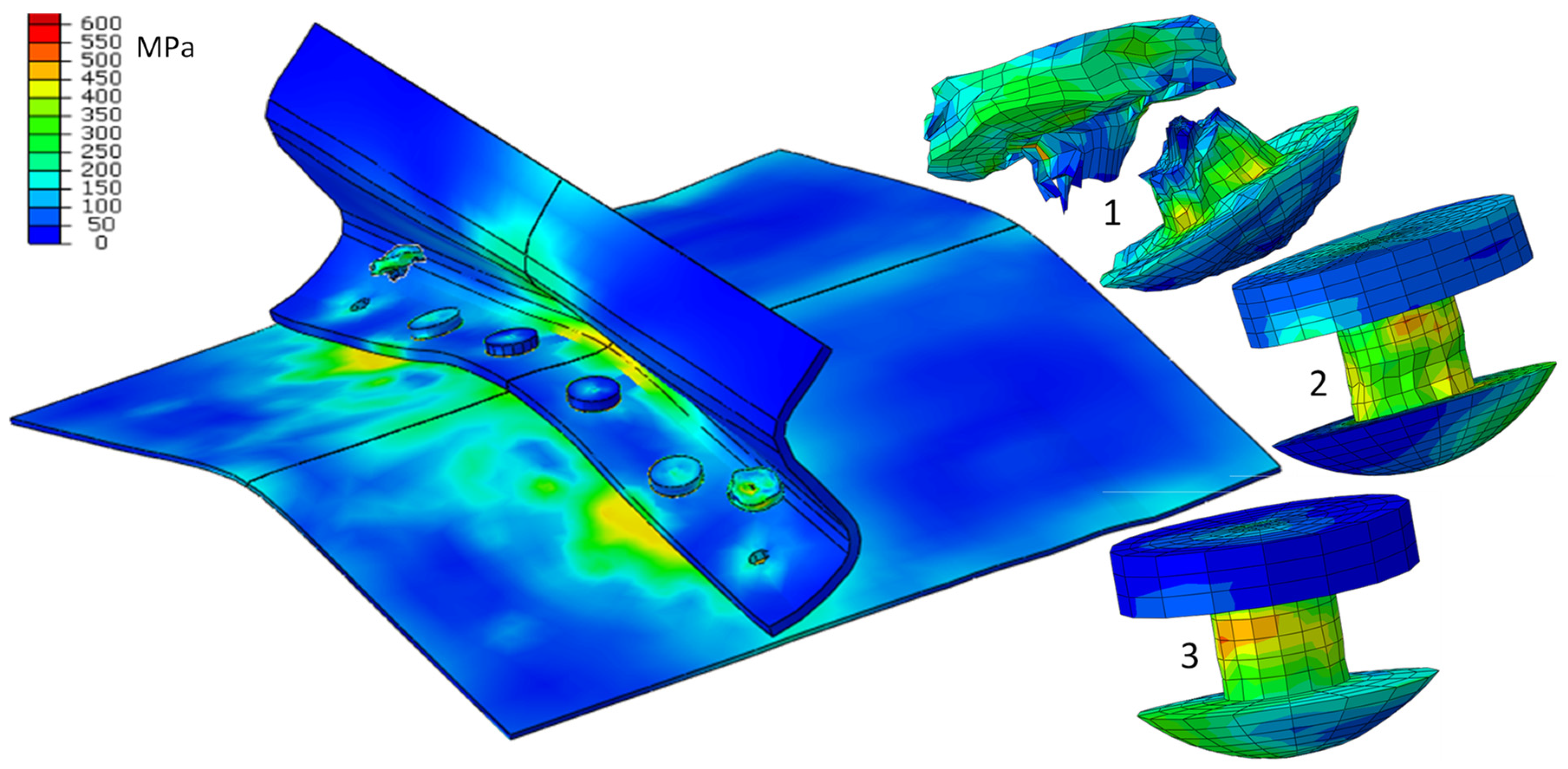
Reduced stress HMH in the elements of aircraft structures, t = 20 ms.
Figure 8.
Reduced stress HMH in the elements of aircraft structures, t = 20 ms.
Figure 9.
State of deformation after an impact, experiment, and FEM simulation.
Figure 9.
State of deformation after an impact, experiment, and FEM simulation.
Figure 10.
Reduced stress HMH in the elements of aircraft structures after impact; t = 90 ms.
Figure 10.
Reduced stress HMH in the elements of aircraft structures after impact; t = 90 ms.
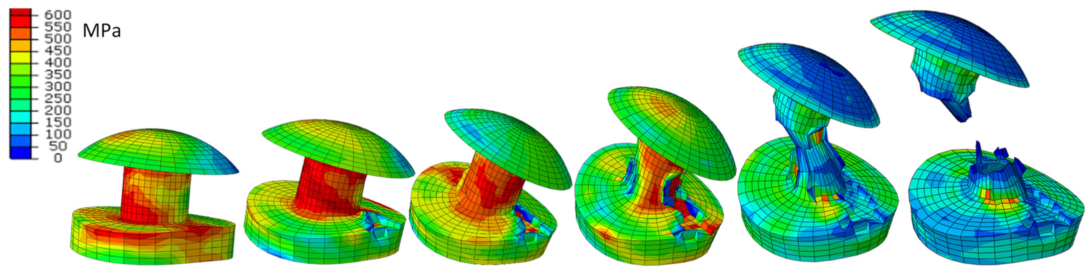
Figure 11.
Deformation and distribution of HMH (MPa) reduced stresses in extreme rivets; t = 5, 10, 20, 30, 40, 48 ms.
Figure 11.
Deformation and distribution of HMH (MPa) reduced stresses in extreme rivets; t = 5, 10, 20, 30, 40, 48 ms.
Figure 12.
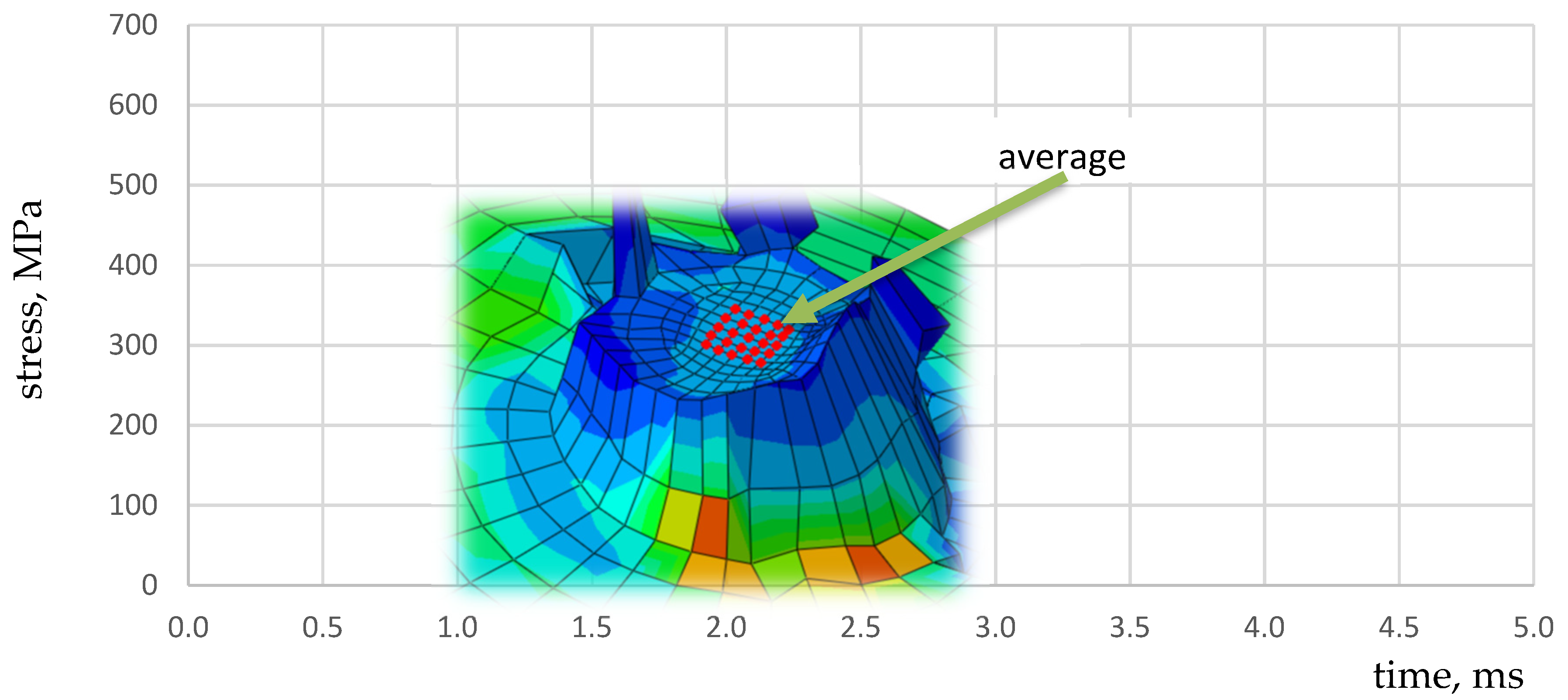
HMH reduced stress distribution in the rivet; the red line indicates average value of the internal nodes is 25.
Figure 12.
HMH reduced stress distribution in the rivet; the red line indicates average value of the internal nodes is 25.
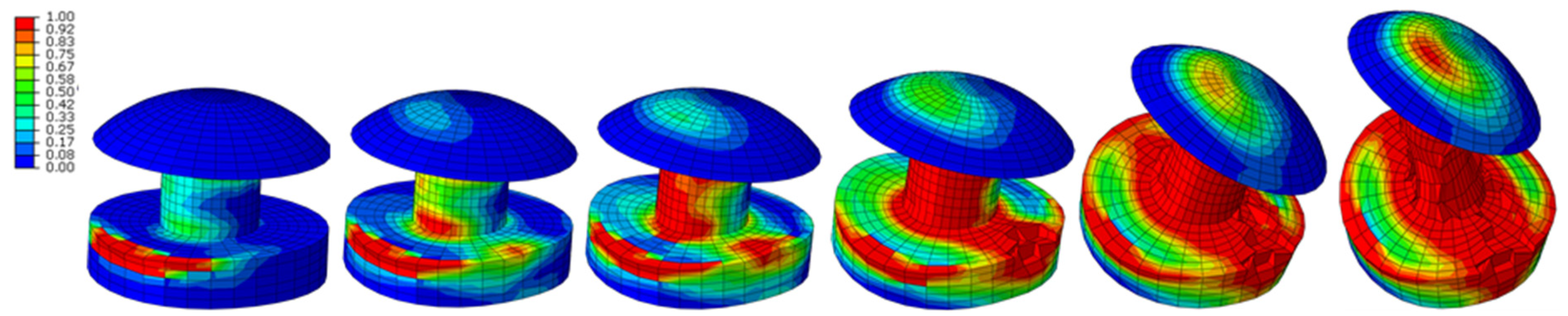
Figure 13.
Development of destruction in the elements of the extreme rivets; t = 3, 5, 6, 8, 20, 39 ms.
Figure 13.
Development of destruction in the elements of the extreme rivets; t = 3, 5, 6, 8, 20, 39 ms.
Figure 14.
The strain rate in the extreme elements of rivets; t = 10 and 38 ms.
Figure 14.
The strain rate in the extreme elements of rivets; t = 10 and 38 ms.
Figure 15.
Notched specimen used in Bridgman’s work.
Figure 15.
Notched specimen used in Bridgman’s work.
Table 1.
Calculation of true and plastic material characteristics.
Table 1.
Calculation of true and plastic material characteristics.
Εnom
Nominal Strain
- | σnom
Nominal Stress
Mpa | εtrue
True Strain
- | εpl
Plastic Strain
- | σtrue
True Stress
MPa |
|---|
| (3) | (4) | (5) | (6) | (7) |
|---|
| | | | |
| 0.00032 | 27.3 | 0.00032 | 0 | 27.3 |
| 0.00218 | 177.8 | 0.00217 | 0 | 178.2 |
| 0.00285 | 229.4 | 0.00285 | 0 | 230.0 |
| εH = 0.0032 | σH = 258.0 | 0.00320 | 0.00001 | 258.8 |
| 0.00355 | 276.7 | 0.00354 | 0.00007 | 277.7 |
| 0.00431 | 319.1 | 0.00430 | 0.00029 | 320.4 |
| 0.00617 | 382.0 | 0.00616 | 0.00134 | 384.4 |
| εe = 0.0068 | Re = 392.6 | εe.true = 0.00675 | εe.pl = 0.00181 | Re.true = 395.3 |
| 0.00746 | 401.5 | 0.00743 | 0.00237 | 404.5 |
| 0.01266 | 429.1 | 0.01258 | 0.00714 | 434.5 |
| 0.03251 | 462.2 | 0.03199 | 0.02602 | 477.2 |
| 0.05680 | 487.7 | 0.05525 | 0.04880 | 515.4 |
| εm = 0.0653 | Rm = 490.0 | 0.06330 | 0.05677 | 522.1 |
| 0.06678 | 489.9 | 0.06465 | 0.05811 | 522.6 |
| 0.06929 | 489.2 | εm.true = 0.0670 | εm.pl = 0.0605 | Rm.true = 523.1 |
| 0.07451 | 485.7 | 0.07187 | 0.06533 | 521.9 |
| 0.10670 | 364.4 | 0.10139 | 0.09633 | 403.3 |
| εf = 0.1103 | Rf = 305.9 | εf.true = 0.1055 | εf.pl = 0.1016 | Rf.true = 313.3 |
Table 2.
Summary of test results on a rotary hammer.
Table 2.
Summary of test results on a rotary hammer.
| Sample Name | φ | Measuring Length | Area
A0 | Breaking Force
Fm | Hammer Rotational Speed | Strain Rate | Dynamic Ultimate Strength Rm |
|---|
| | mm | mm | mm2 | kN | m/s | s−1 | MPa |
|---|
| Al7.5Mg_v1 | 5.05 | 18.69 | 20.03 | 12.65 | 10 | 535 | 631.6 |
| Al7.5Mg_v2 | 5.04 | 19.36 | 19.95 | 12.80 | 20 | 1033 | 641.6 |
| Al7.5Mg_v3 | 5.08 | 19.33 | 20.27 | 13.08 | 30 | 1552 | 645.3 |
| Al7.5Mg_v4 | 5.06 | 18.53 | 20.11 | 13.07 | 40 | 2159 | 650.0 |
Table 3.
Ultimate strength m,nom, , , C for various strain rates.
Table 3.
Ultimate strength m,nom, , , C for various strain rates.
| Strain Rate | | | | | |
|---|
| , MPa | 490 | 631 | 641 | 645 | 649 |
| , MPa | 523 | 672 | 683 | 687 | 692 |
| , MPa | 523 | 676 | 682 | 686 | 689 |
| C | - | 0.01847 | 0.01898 | 0.01897 | 0.01916 |
Table 4.
The values of the triaxiality coefficient for selected 3D cases [
32].
Table 4.
The values of the triaxiality coefficient for selected 3D cases [
32].
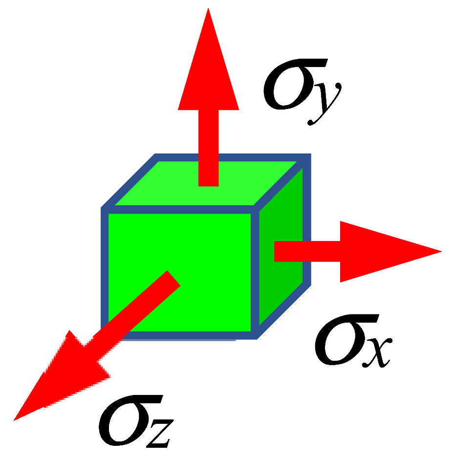
| | ![Materials 15 01920 i001]() | ![Materials 15 01920 i002]() | ![Materials 15 01920 i003]() |
|
| Principal stresses | σx = σy = σz > 0 | σx = σy
σz = 0 | σx > 0
σy = σz = 0 |
| ηTRIAX | ∞ | 0.66 | 0.33 |
Table 5.
The values in
Figure 3 used in the calculations.
Table 5.
The values in
Figure 3 used in the calculations.
| Point Label | Strain | Stress | Remarks |
|---|
| | | | |
|---|
| A | 0.0040 | 258.0 | |
| 1 | 0.0068 | 395.3 | Yield point Re |
| 2 | 0.0671 | 523.1 | Ultimate tensile strength Rm |
| 3 | 0.1055 | 313.3 | Sample fracture |
| 4 | 0.1140 | 0.00 | d = 1 material total degradation |
| 5 | 0.1055 | 550.1 | Stresses in the material model without failure parameters |
| 6 | 0.0987 | 0.00 | Fracture deformation |
| 7 | 0.0590 | 0.00 | Deformation at ultimate strength Rm, d = 0 |
| Publisher’s Note: MDPI stays neutral with regard to jurisdictional claims in published maps and institutional affiliations. |
© 2022 by the authors. Licensee MDPI, Basel, Switzerland. This article is an open access article distributed under the terms and conditions of the Creative Commons Attribution (CC BY) license (https://creativecommons.org/licenses/by/4.0/).


