
Review of the Electrospinning Process and the Electro-Conversion of 5-Hydroxymethylfurfural (HMF) into Added-Value Chemicals


Abstract
:1. Introduction
2. Synthesis of PAN Fibers and Gold Nanoparticles
2.1. Formulation of a Suitable Electrospinning Solution
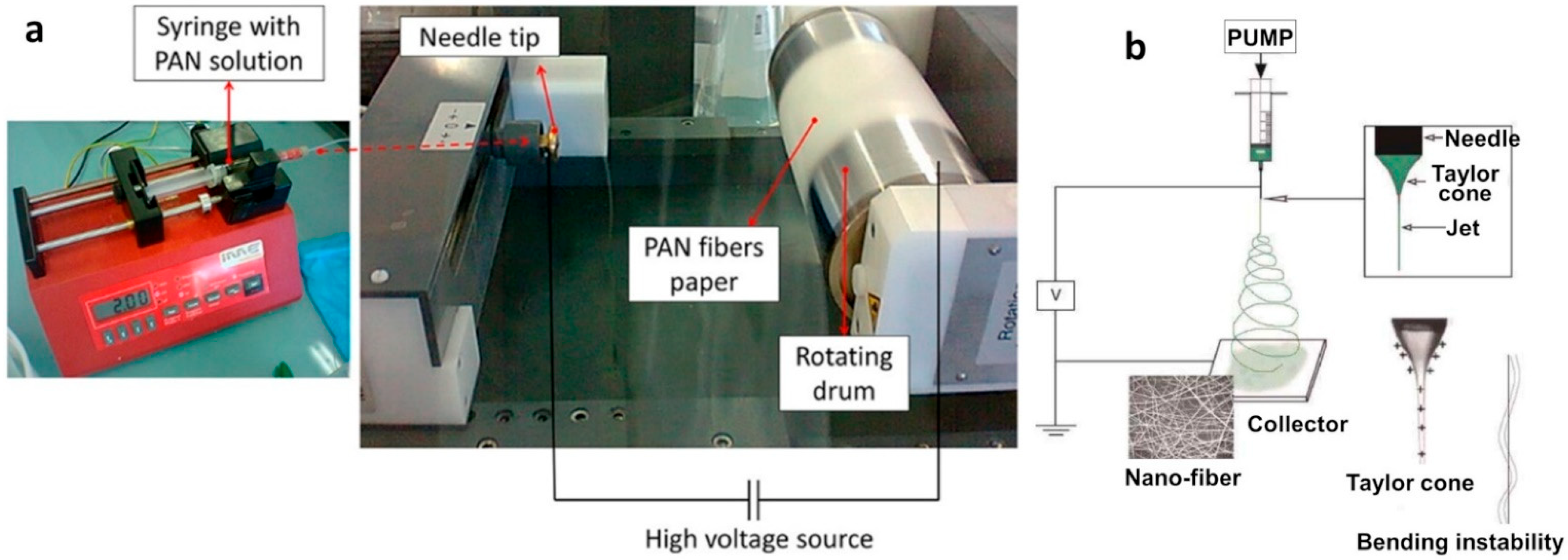
2.2. Electrospinning Process
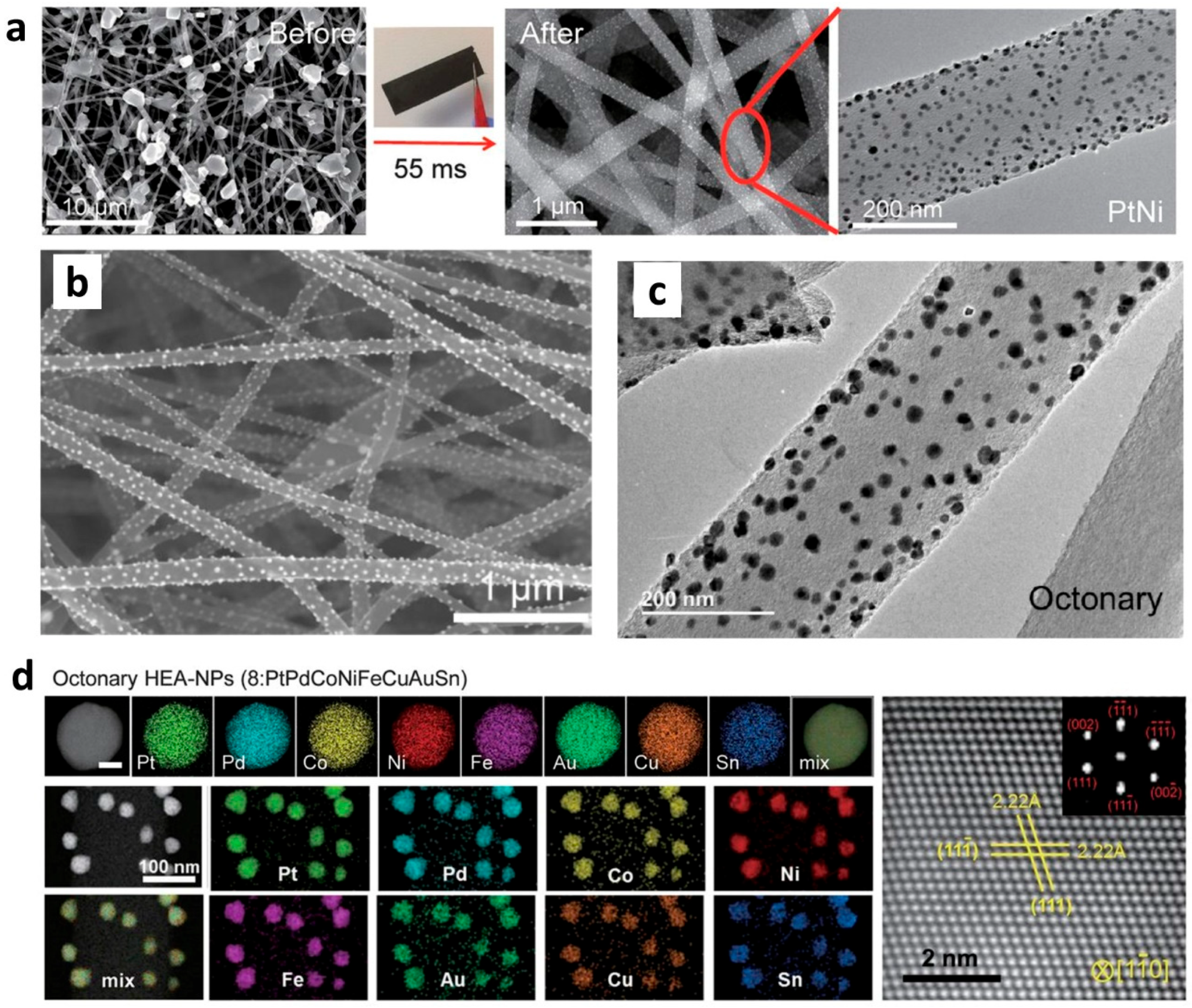
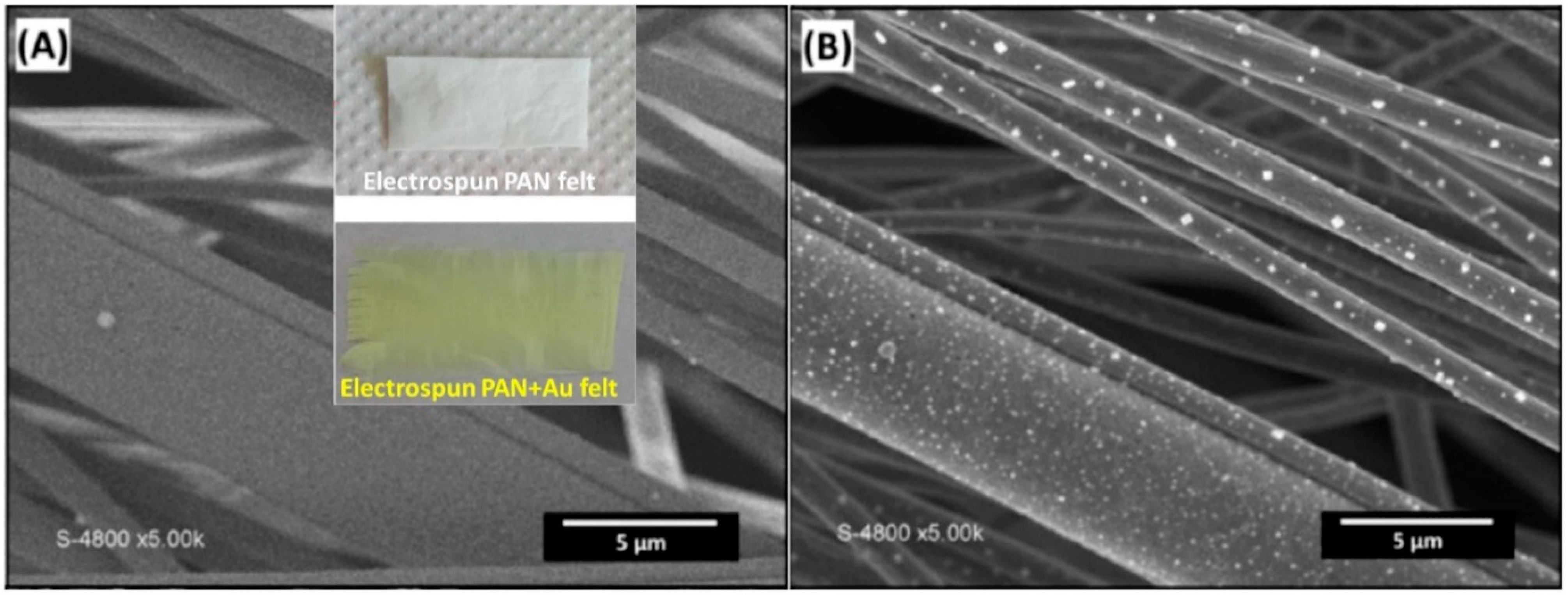
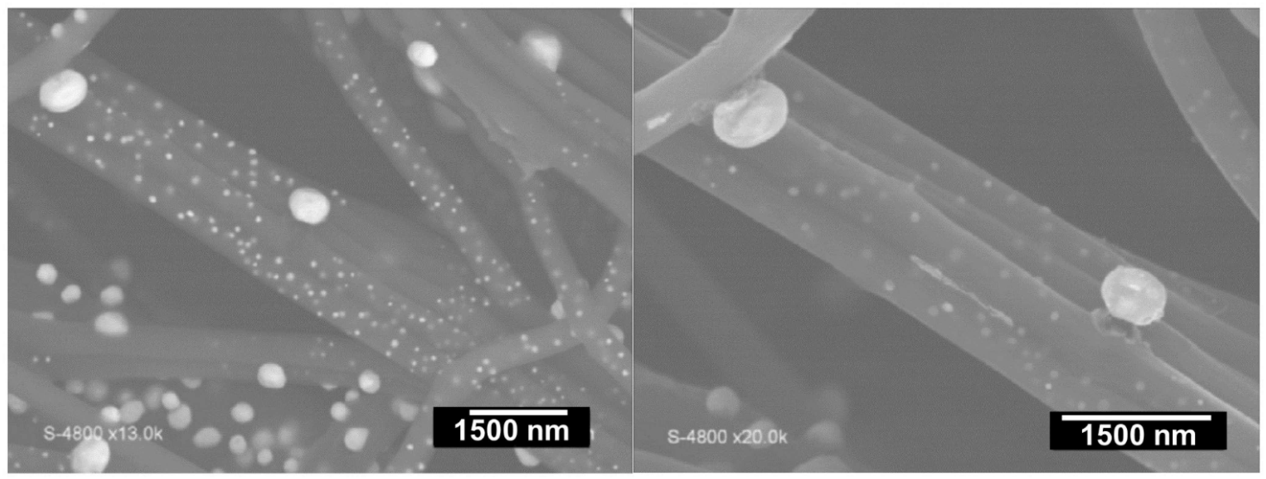
2.3. Formation and Synthesis of Nanoparticles

| Material | Solvent | Reference |
|---|---|---|
| Ni/N,S-doped carbon | DMF | [48] |
| CoSe/N-doped carbon | DMF | [71] |
| Fe3O4/N-doped carbon | DMF | [49] |
| WS2/N-doped carbon | DMF | [50] |
| MnCo2O4@N-doped carbon | DMF | [51] |
| Co3O4-CNFs (CNF: carbon nanofibers) | DMF | [72] |
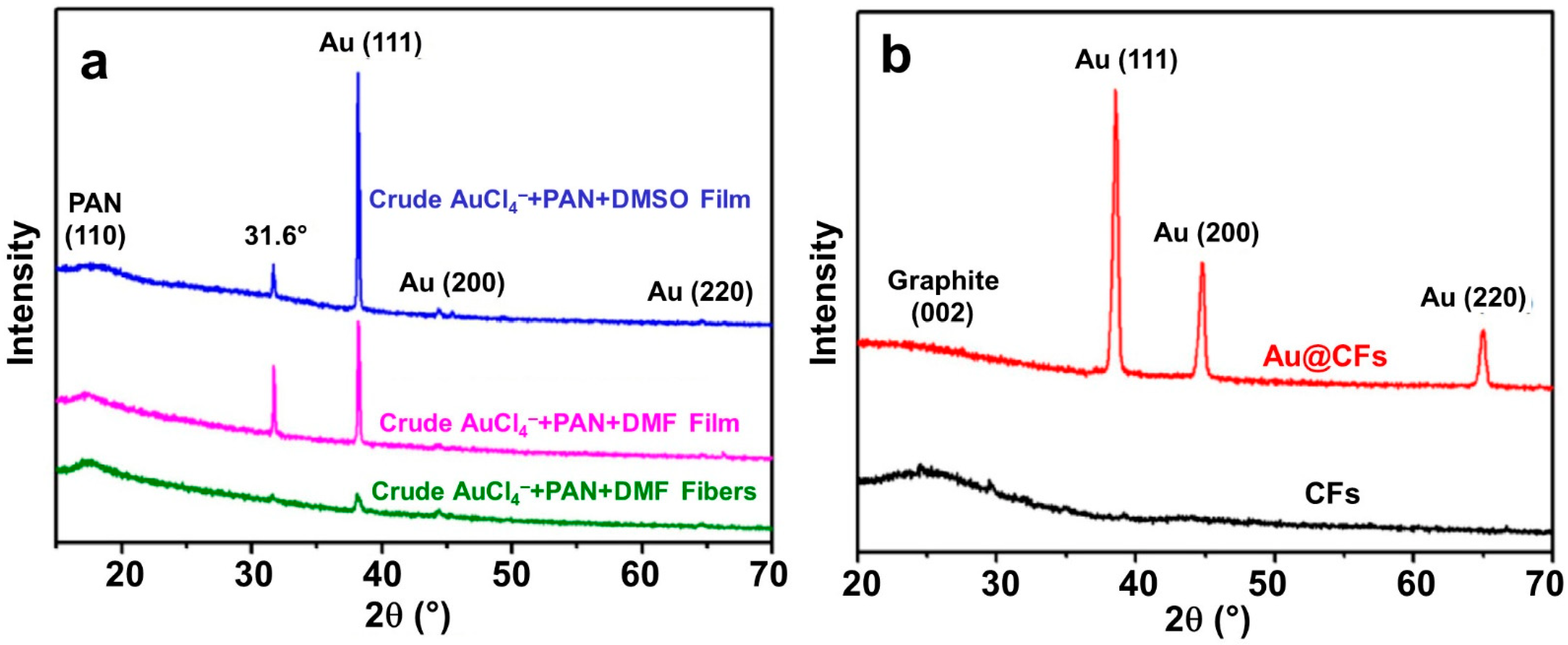
| Au@CFs (CFs: carbon fibers) | DMF | [34] |
| Casein/PAN | DMSO | [42] |
| Li/CNFs | DMF | [35] |
| NCNFs (nitrogen-doped electrospun carbon nanofibers) | DMF | [45] |
| PAN NFM (polyacrylonitrile electrospun nanofibrous membrane) | DMF | [41] |
2.4. Process of Electrospinning for PAN
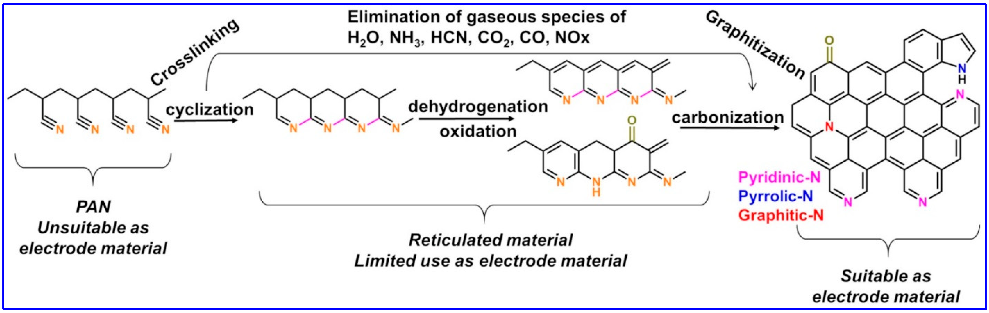
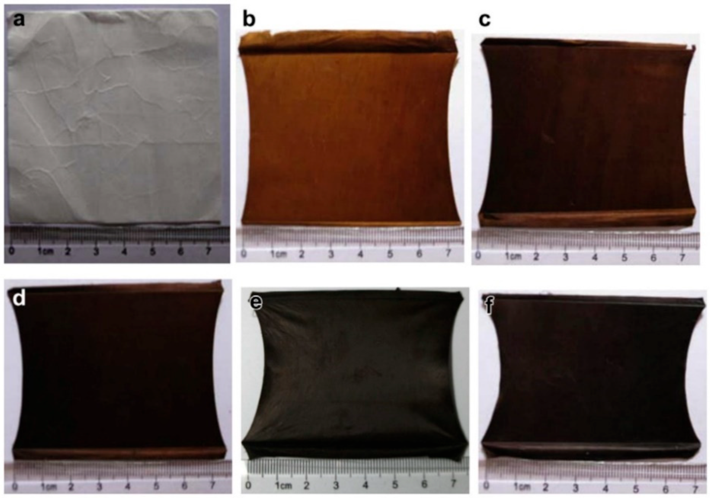
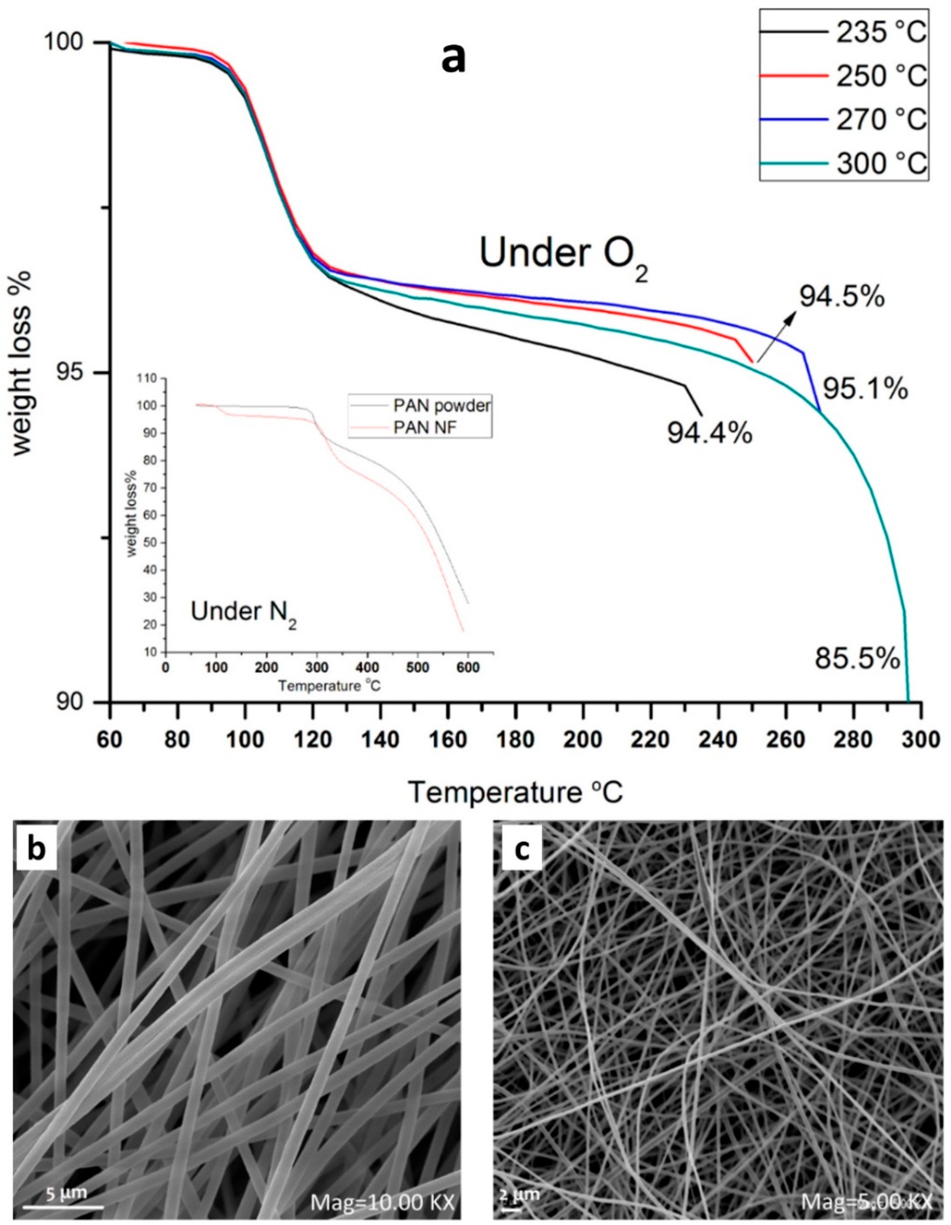
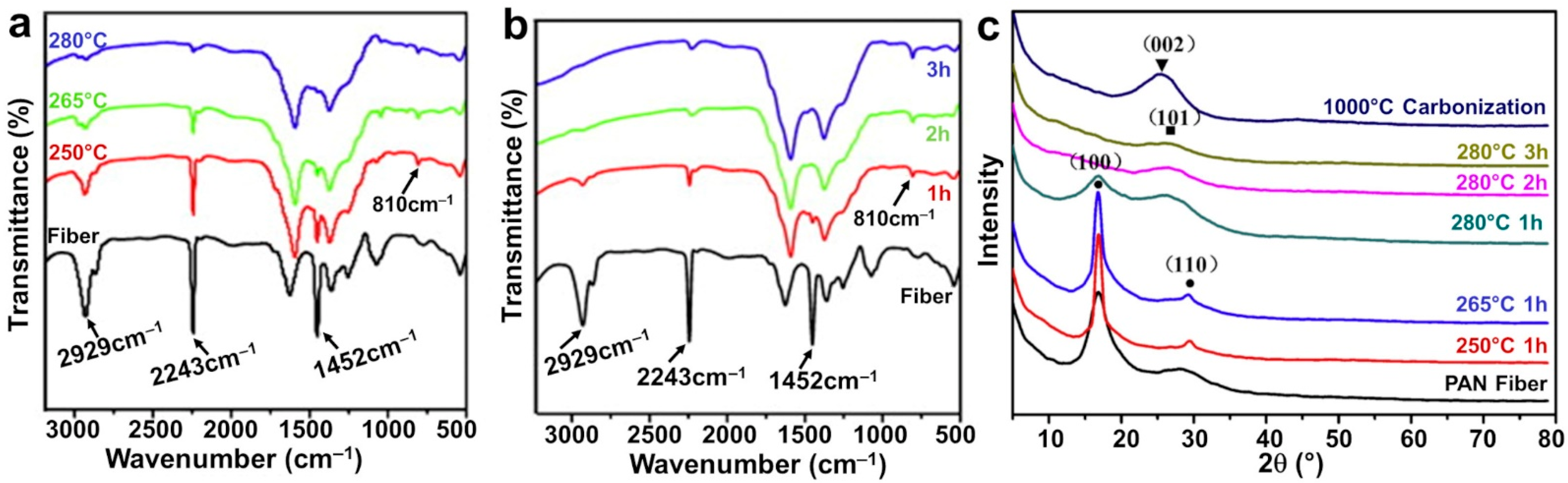
2.5. Thermal Treatment
2.6. Other Characterizations of the Mat Fibers
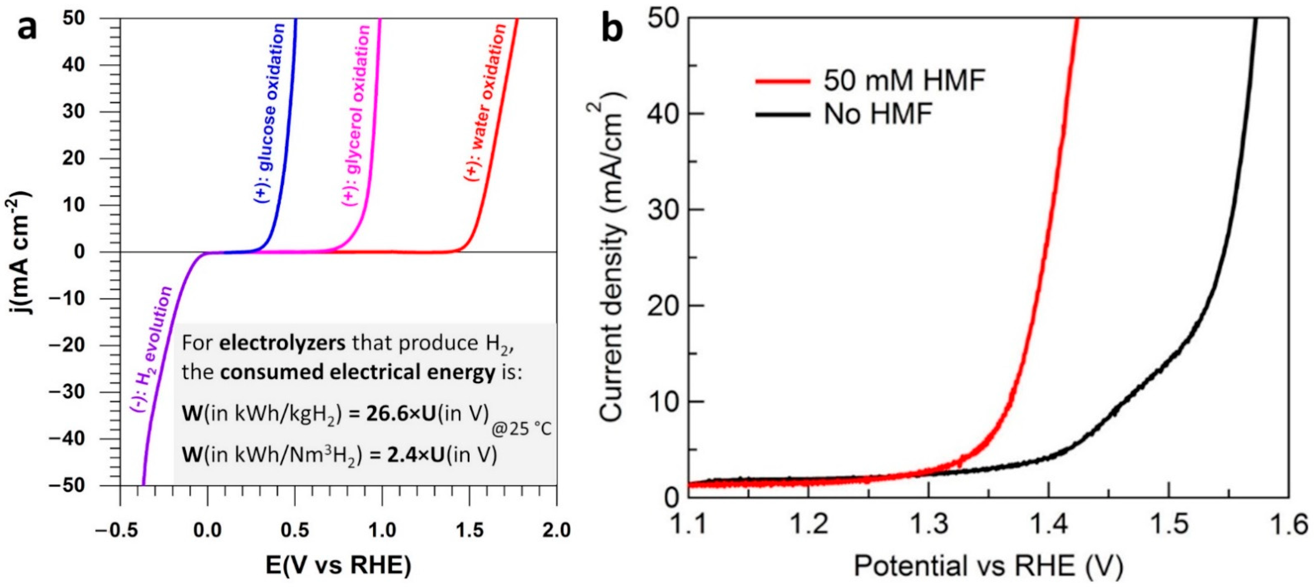
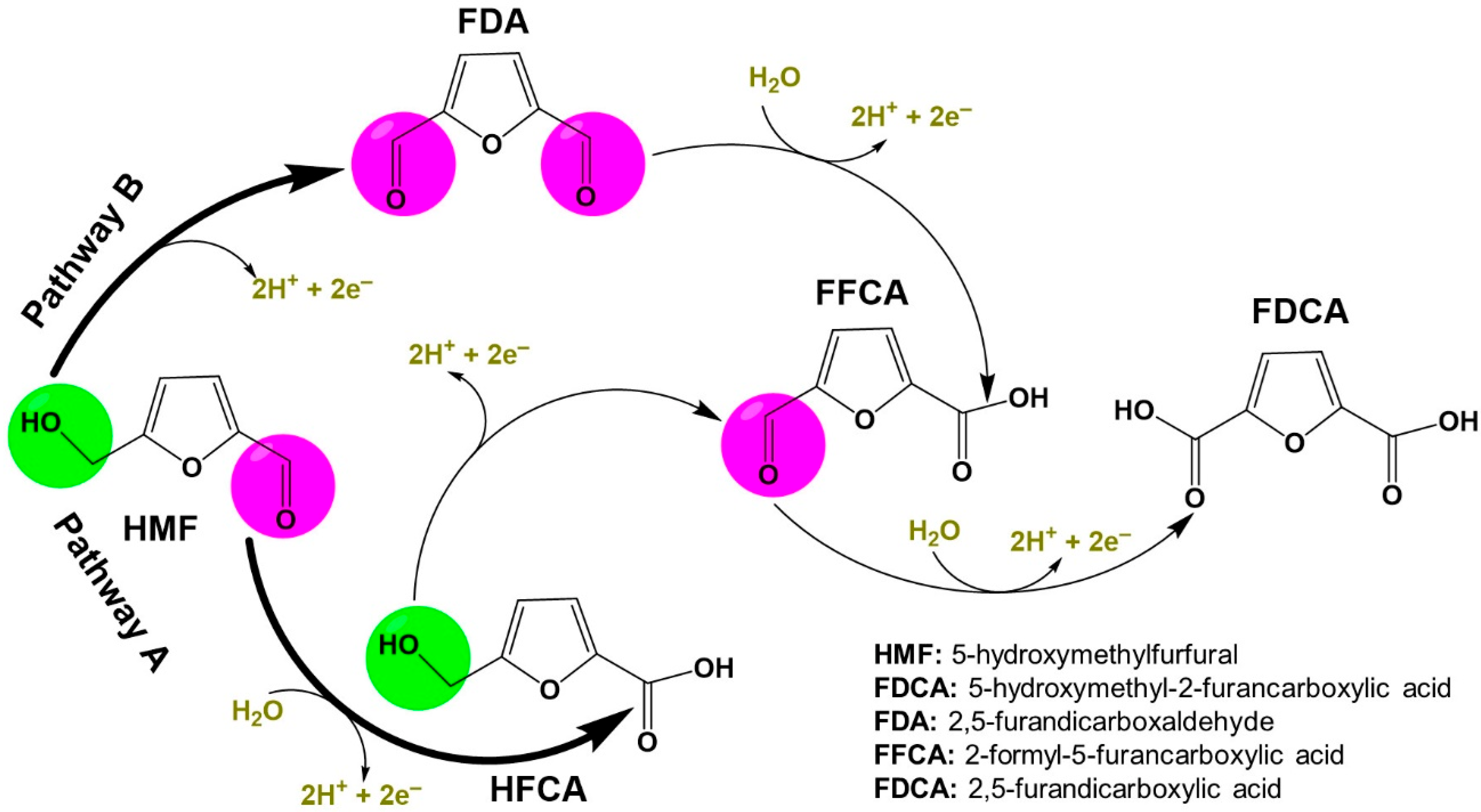
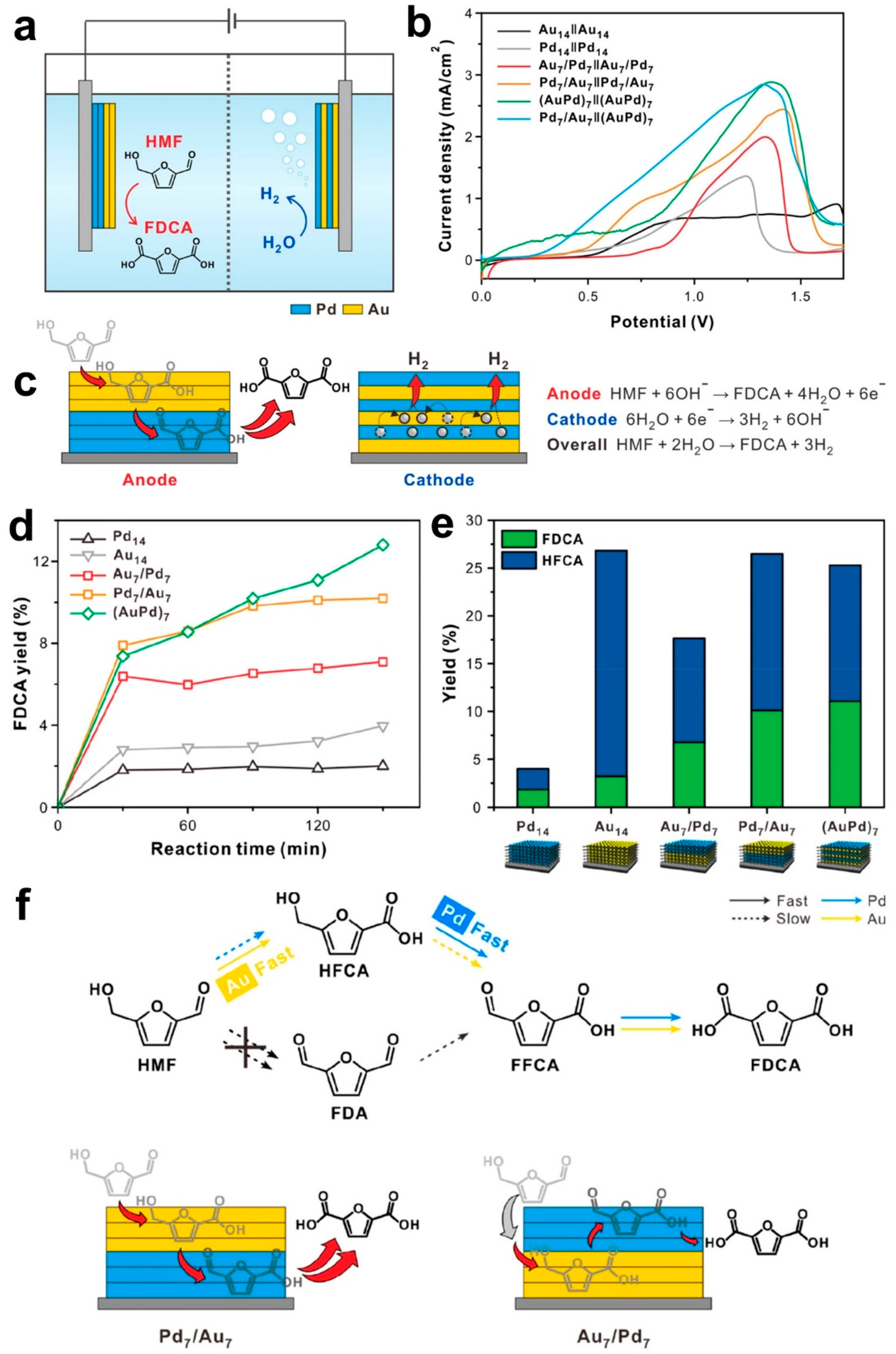
3. HMF Electrooxidation for Paired Electrosynthesis of Valuable Chemicals
4. Conclusions and Perspective
Author Contributions
Funding
Institutional Review Board Statement
Informed Consent Statement
Data Availability Statement
Conflicts of Interest
References
- Bond, A.M. Broadening Electrochemical Horizons: Principles and Illustration of Voltammetric and Related Techniques; Oxford University Press Inc.: New York, NY, USA, 2002; p. 532. [Google Scholar]
- Kisszekelyi, P.; Hardian, R.; Vovusha, H.; Chen, B.L.; Zeng, X.H.; Schwingenschlogl, U.; Kupai, J.; Szekely, G. Selective Electrocatalytic Oxidation of Biomass-Derived 5-Hydroxymethylfurfural to 2,5-Diformylfuran: From Mechanistic Investigations to Catalyst Recovery. Chemsuschem 2020, 13, 3127–3136. [Google Scholar] [CrossRef] [PubMed]
- Luna, P.D.; Hahn, C.; Higgins, D.; Jaffer, S.A.; Jaramillo, T.F.; Sargent, E.H. What would it take for renewably powered electrosynthesis to displace petrochemical processes? Science 2019, 364, eaav3506. [Google Scholar] [CrossRef] [Green Version]
- Montoya, J.H.; Seitz, L.C.; Chakthranont, P.; Vojvodic, A.; Jaramillo, T.F.; Norskov, J.K. Materials for solar fuels and chemicals. Nat. Mater. 2017, 16, 70–81. [Google Scholar] [CrossRef] [PubMed]
- Xue, J.; Wu, T.; Dai, Y.; Xia, Y. Electrospinning and Electrospun Nanofibers: Methods, Materials, and Applicaations. Chem. Rev. 2019, 119, 5298–5415. [Google Scholar] [CrossRef]
- Holade, Y.; Tuleushova, N.; Tingry, S.; Servat, K.; Napporn, T.W.; Guesmi, H.; Cornu, D.; Kokoh, K.B. Recent advances in the electrooxidation of biomass-based organic molecules for energy, chemicals and hydrogen production. Catal. Sci. Technol. 2020, 10, 3071–3112. [Google Scholar] [CrossRef]
- Dai, J. Synthesis of 2,5-diformylfuran from renewable carbohydrates and its applications: A review. Green Energy Environ. 2021, 6, 22–32. [Google Scholar] [CrossRef]
- Kwon, Y.; Schouten, K.J.P.; van der Waal, J.C.; de Jong, E.; Koper, M.T.M. Electrocatalytic Conversion of Furanic Compounds. ACS Catal. 2016, 6, 6704–6717. [Google Scholar] [CrossRef]
- Rosatella, A.A.; Simeonov, S.P.; Frade, R.F.M.; Afonso, C.A.M. 5-Hydroxymethylfurfural (HMF) as a building block platform: Biological properties, synthesis and synthetic applications. Green Chem. 2011, 13, 754–793. [Google Scholar] [CrossRef]
- Patel, P.; Schwartz, D.; Wang, X.; Lin, R.; Ajao, O.; Seifitokaldani, A. Technoeconomic and Life-Cycle Assessment for Electrocatalytic Production of Furandicarboxylic Acid. ACS Sustain. Chem. Eng. 2022, 10, 4206–4217. [Google Scholar] [CrossRef]
- Lucas, F.W.S.; Grim, R.G.; Tacey, S.A.; Downes, C.A.; Hasse, J.; Roman, A.M.; Farberow, C.A.; Schaidle, J.A.; Holewinski, A. Electrochemical Routes for the Valorization of Biomass-Derived Feedstocks: From Chemistry to Application. ACS Energy Lett. 2021, 6, 1205–1270. [Google Scholar] [CrossRef]
- Jiang, N.; You, B.; Boonstra, R.; Terrero Rodriguez, I.M.; Sun, Y. Integrating Electrocatalytic 5-Hydroxymethylfurfural Oxidation and Hydrogen Production via Co–P-Derived Electrocatalysts. ACS Energy Lett. 2016, 1, 386–390. [Google Scholar] [CrossRef]
- Chadderdon, D.J.; Xin, L.; Qi, J.; Qiu, Y.; Krishna, P.; More, K.L.; Li, W. Electrocatalytic oxidation of 5-hydroxymethylfurfural to 2,5-furandicarboxylic acid on supported Au and Pd bimetallic nanoparticles. Green Chem. 2014, 16, 3778–3786. [Google Scholar] [CrossRef]
- Ermakova, M.A.; Ermakov, D.Y.; Kuvshinov, G.G. Effective catalysts for direct cracking of methane to produce hydrogen and filamentous carbon: Part I. Nickel catalysts. Appl. Catal. A Gen. 2000, 201, 61–70. [Google Scholar] [CrossRef]
- Inocêncio, C.V.M.; Holade, Y.; Morais, C.; Kokoh, K.B.; Napporn, T.W. Electrochemical hydrogen generation technology: Challenges in electrodes materials for a sustainable energy. Electrochem. Sci. Adv. 2022, e2100206. [Google Scholar] [CrossRef]
- Park, M.; Gu, M.; Kim, B.-S. Tailorable Electrocatalytic 5-Hydroxymethylfurfural Oxidation and H2 Production: Architecture–Performance Relationship in Bifunctional Multilayer Electrodes. ACS Nano 2020, 14, 6812–6822. [Google Scholar] [CrossRef]
- Zhang, L.; Zhao, H.; Xu, S.; Liu, Q.; Li, T.; Luo, Y.; Gao, S.; Shi, X.; Asiri, A.M.; Sun, X. Recent Advances in 1D Electrospun Nanocatalysts for Electrochemical Water Splitting. Small Struct. 2021, 2, 2000048. [Google Scholar] [CrossRef]
- Stamenkovic, V.R.; Strmcnik, D.; Lopes, P.P.; Markovic, N.M. Energy and fuels from electrochemical interfaces. Nat. Mater. 2017, 16, 57–69. [Google Scholar] [CrossRef]
- Assaud, L.; Brazeau, N.; Barr, M.K.S.; Hanbucken, M.; Ntais, S.; Baranova, E.A.; Santinacci, L. Atomic Layer Deposition of Pd Nanoparticles on TiO2 Nanotubes for Ethanol Electrooxidation: Synthesis and Electrochemical Properties. ACS Appl. Mater. Interfaces 2015, 7, 24533–24542. [Google Scholar] [CrossRef]
- Hajar, Y.; Di Palma, V.; Kyriakou, V.; Verheijen, M.A.; Baranova, E.A.; Vernoux, P.; Kessels, W.M.M.; Creatore, M.; van de Sanden, M.C.M.; Tsampas, M.N. Atomic layer deposition of highly dispersed Pt nanoparticles on a high surface area electrode backbone for electrochemical promotion of catalysis. Electrochem. Commun. 2017, 84, 40–44. [Google Scholar] [CrossRef] [Green Version]
- Weber, M.; Tuleushova, N.; Zgheib, J.; Lamboux, C.; Iatsunskyi, I.; Coy, E.; Flaud, V.; Tingry, S.; Cornu, D.; Miele, P.; et al. Enhanced electrocatalytic performance triggered by atomically bridged boron nitride between palladium nanoparticles and carbon fibers in gas-diffusion electrodes. Appl. Catal. B Environ. 2019, 257, 117917. [Google Scholar] [CrossRef]
- Weber, M.; Collot, P.; El Gaddari, H.; Tingry, S.; Bechelany, M.; Holade, Y. Enhanced Catalytic Glycerol Oxidation Activity Enabled by Activated-Carbon-Supported Palladium Catalysts Prepared through Atomic Layer Deposition. ChemElectroChem 2018, 5, 743–747. [Google Scholar] [CrossRef]
- Zhang, R.; Wei, H.; Si, W.; Ou, G.; Zhao, C.; Song, M.; Zhang, C.; Wu, H. Enhanced Electrocatalytic Activity for Water Splitting on NiO/Ni/Carbon Fiber Paper. Materials 2017, 10, 15. [Google Scholar] [CrossRef] [PubMed]
- Cavaliere, S.; Subianto, S.; Savych, I.; Jones, D.J.; Roziere, J. Electrospinning: Designed architectures for energy conversion and storage devices. Energy Environ. Sci. 2011, 4, 4761–4785. [Google Scholar] [CrossRef] [Green Version]
- Sood, R.; Cavaliere, S.; Jones, D.J.; Rozière, J. Electrospun nanofibre composite polymer electrolyte fuel cell and electrolysis membranes. Nano Energy 2016, 26, 729–745. [Google Scholar] [CrossRef] [Green Version]
- Xue, J.; Xie, J.; Liu, W.; Xia, Y. Electrospun Nanofibers: New Concepts, Materials, and Applications. Acc. Chem. Res. 2017, 50, 1976–1987. [Google Scholar] [CrossRef]
- Rodríguez-Tobías, H.; Morales, G.; Grande, D. Comprehensive review on electrospinning techniques as versatile approaches toward antimicrobial biopolymeric composite fibers. Mater. Sci. Eng. C 2019, 101, 306–322. [Google Scholar] [CrossRef]
- Saleh, A.; Marhuenda, E.; Fabre, C.; Hassani, Z.; Weille, J.D.; Boukhaddaoui, H.; Guelfi, S.; Maldonado, I.L.; Hugnot, J.-P.; Duffau, H.; et al. A novel 3D nanofibre scaffold conserves the plasticity of glioblastoma stem cell invasion by regulating galectin-3 and integrin-β1 expression. Sci. Rep. 2019, 9, 14612. [Google Scholar] [CrossRef] [Green Version]
- Marhuenda, E.; Fabre, C.; Zhang, C.; Martin-Fernandez, M.; Iskratsch, T.; Saleh, A.; Bauchet, L.; Cambedouzou, J.; Hugnot, J.-P.; Duffau, H.; et al. Glioma stem cells invasive phenotype at optimal stiffness is driven by MGAT5 dependent mechanosensing. J. Exp. Clin. Cancer Res. 2021, 40, 139. [Google Scholar] [CrossRef]
- Pastoriza-Santos, I.; Liz-Marzán, L.M. N,N-Dimethylformamide as a Reaction Medium for Metal Nanoparticle Synthesis. Adv. Funct. Mater. 2009, 19, 679–688. [Google Scholar] [CrossRef]
- Saquing, C.D.; Manasco, J.L.; Khan, S.A. Electrospun Nanoparticle–Nanofiber Composites via a One-Step Synthesis. Small 2009, 5, 944–951. [Google Scholar] [CrossRef]
- Wang, Y.; Li, Y.; Sun, G.; Zhang, G.; Liu, H.; Du, J.; Yang, S.; Bai, J.; Yang, Q. Fabrication of Au/PVP nanofiber composites by electrospinning. J. Appl. Polym. Sci. 2007, 105, 3618–3622. [Google Scholar] [CrossRef]
- Casasola, R.; Thomas, N.L.; Trybala, A.; Georgiadou, S. Electrospun poly lactic acid (PLA) fibres: Effect of different solvent systems on fibre morphology and diameter. Polymer 2014, 55, 4728–4737. [Google Scholar] [CrossRef] [Green Version]
- Both Engel, A.; Bechelany, M.; Fontaine, O.; Cherifi, A.; Cornu, D.; Tingry, S. One-Pot Route to Gold Nanoparticles Embedded in Electrospun Carbon Fibers as an Efficient Catalyst Material for Hybrid Alkaline Glucose Biofuel Cells. ChemElectroChem 2016, 3, 629–637. [Google Scholar] [CrossRef]
- Zhang, B.; Yu, Y.; Xu, Z.-L.; Abouali, S.; Akbari, M.; He, Y.-B.; Kang, F.; Kim, J.-K. Correlation Between Atomic Structure and Electrochemical Performance of Anodes Made from Electrospun Carbon Nanofiber Films. Adv. Energy Mater. 2014, 4, 1301448. [Google Scholar] [CrossRef]
- Thavasi, V.; Singh, G.; Ramakrishna, S. Electrospun nanofibers in energy and environmental applications. Energy Environ. Sci. 2008, 1, 205–221. [Google Scholar] [CrossRef]
- Xue, T.J.; McKinney, M.A.; Wilkie, C.A. The thermal degradation of polyacrylonitrile. Polym. Degrad. Stab. 1997, 58, 193–202. [Google Scholar] [CrossRef]
- Badii, K.; Church, J.S.; Golkarnarenji, G.; Naebe, M.; Khayyam, H. Chemical structure based prediction of PAN and oxidized PAN fiber density through a non-linear mathematical model. Polym. Degrad. Stab. 2016, 131, 53–61. [Google Scholar] [CrossRef]
- Holade, Y.; Both Engel, A.; Tingry, S.; Cherifi, A.; Cornu, D.; Servat, K.; Napporn, T.W.; Kokoh, K.B. Insights on Hybrid Glucose Biofuel Cell Based on Bilirubin Oxidase Cathode and Gold-Based Nanomaterials Anode. ChemElectroChem 2014, 1, 1976–1987. [Google Scholar] [CrossRef]
- Aslan, S.; Bal Altuntaş, D.; Koçak, Ç.; Kara Subaşat, H. Electrochemical Evaluation of Titanium (IV) Oxide/Polyacrylonitrile Electrospun Discharged Battery Coals as Supercapacitor Electrodes. Electroanalysis 2021, 33, 120–128. [Google Scholar] [CrossRef]
- Li, S.-F.; Chen, J.-P.; Wu, W.-T. Electrospun polyacrylonitrile nanofibrous membranes for lipase immobilization. J. Mol. Catal. B Enz. 2007, 47, 117–124. [Google Scholar] [CrossRef]
- Diestelhorst, E.; Mance, F.; Mamun, A.; Ehrmann, A. Chemical and Morphological Modification of PAN Nanofibrous Mats with Addition of Casein after Electrospinning, Stabilisation and Carbonisation. Tekstilec 2020, 63, 38–49. [Google Scholar] [CrossRef]
- Rodríguez-Tobías, H.; Morales, G.; Ledezma, A.; Romero, J.; Saldívar, R.; Langlois, V.; Renard, E.; Grande, D. Electrospinning and electrospraying techniques for designing novel antibacterial poly(3-hydroxybutyrate)/zinc oxide nanofibrous composites. J. Mater. Sci. 2016, 51, 8593–8609. [Google Scholar] [CrossRef]
- Che, A.-F.; Germain, V.; Cretin, M.; Cornu, D.; Innocent, C.; Tingry, S. Fabrication of free-standing electrospun carbon nanofibers as efficient electrode materials for bioelectrocatalysis. New J. Chem. 2011, 35, 2848–2853. [Google Scholar] [CrossRef]
- Wang, S.; Dai, C.; Li, J.; Zhao, L.; Ren, Z.; Ren, Y.; Qiu, Y.; Yu, J. The effect of different nitrogen sources on the electrocatalytic properties of nitrogen-doped electrospun carbon nanofibers for the oxygen reduction reaction. Int. J. Hydrogen Energy 2015, 40, 4673–4682. [Google Scholar] [CrossRef]
- Sawada, K.; Sakai, S.; Taya, M. Polyacrylonitrile-based electrospun nanofibers carrying gold nanoparticles in situ formed by photochemical assembly. J. Mater. Sci. 2014, 49, 4595–4600. [Google Scholar] [CrossRef]
- Anka, F.H.; Perera, S.D.; Ratanatawanate, C.; Balkus, K.J. Polyacrylonitrile gold nanoparticle composite electrospun fibers prepared by in situ photoreduction. Mater. Lett. 2012, 75, 12–15. [Google Scholar] [CrossRef]
- Liu, D.; Li, W.; Li, L.; Ling, H.; You, T. Facile preparation of Ni nanowire embedded nitrogen and sulfur dual-doped carbon nanofibers and its superior catalytic activity toward urea oxidation. J. Colloid Int. Sci. 2018, 529, 337–344. [Google Scholar] [CrossRef]
- Guo, L.; Sun, H.; Qin, C.; Li, W.; Wang, F.; Song, W.; Du, J.; Zhong, F.; Ding, Y. Flexible Fe3O4 nanoparticles/N-doped carbon nanofibers hybrid film as binder-free anode materials for lithium-ion batteries. Appl. Surf. Sci. 2018, 459, 263–270. [Google Scholar] [CrossRef]
- Yu, X.; Pei, C.; Chen, W.; Feng, L. 2 dimensional WS2 tailored nitrogen-doped carbon nanofiber as a highly pseudocapacitive anode material for lithium-ion battery. Electrochim. Acta 2018, 272, 119–126. [Google Scholar] [CrossRef]
- Cai, N.; Fu, J.; Chan, V.; Liu, M.; Chen, W.; Wang, J.; Zeng, H.; Yu, F. MnCo2O4@nitrogen-doped carbon nanofiber composites with meso-microporous structure for high-performance symmetric supercapacitors. J. Alloys Compd. 2019, 782, 251–262. [Google Scholar] [CrossRef]
- Wu, M.; Wang, Q.; Li, K.; Wu, Y.; Liu, H. Optimization of stabilization conditions for electrospun polyacrylonitrile nanofibers. Polym. Degrad. Stab. 2012, 97, 1511–1519. [Google Scholar] [CrossRef]
- Gergin, İ.; Ismar, E.; Sarac, A.S. Oxidative stabilization of polyacrylonitrile nanofibers and carbon nanofibers containing graphene oxide (GO): A spectroscopic and electrochemical study. Beilstein J. Nanotechnol. 2017, 8, 1616–1628. [Google Scholar] [CrossRef] [PubMed] [Green Version]
- Both Engel, A.; Holade, Y.; Tingry, S.; Cherifi, A.; Cornu, D.; Servat, K.; Napporn, T.W.; Kokoh, K.B. Electrospun Carbon Fibers: Promising Electrode Material for Abiotic and Enzymatic Catalysis. J. Phys. Chem. C 2015, 119, 16724–16733. [Google Scholar] [CrossRef]
- Chronakis, I.S. Chapter 22—Micro- and Nano-fibers by Electrospinning Technology: Processing, Properties, and Applications. In Micromanufacturing Engineering and Technology, 2nd ed.; Qin, Y., Ed.; Elsevier Inc.: Boston, MA, USA, 2015; pp. 513–548. [Google Scholar] [CrossRef]
- Khan, W.S. Chemical and thermal investigations of electrospun polyacrylonitrile nanofibers incorporated with various nanoscale inclusions. J. Therm. Eng. 2017, 3, 1375–1390. [Google Scholar] [CrossRef]
- Bhardwaj, N.; Kundu, S.C. Electrospinning: A fascinating fiber fabrication technique. Biotechnol. Adv. 2010, 28, 325–347. [Google Scholar] [CrossRef]
- Huang, Z.-M.; Zhang, Y.Z.; Kotaki, M.; Ramakrishna, S. A review on polymer nanofibers by electrospinning and their applications in nanocomposites. Compos. Sci. Technol. 2003, 63, 2223–2253. [Google Scholar] [CrossRef]
- Lei, Y.; Wang, Q.; Peng, S.; Ramakrishna, S.; Zhang, D.; Zhou, K. Electrospun Inorganic Nanofibers for Oxygen Electrocatalysis: Design, Fabrication, and Progress. Adv. Energy Mater. 2020, 10, 1902115. [Google Scholar] [CrossRef]
- Li, Z.; Wang, C. Effects of Working Parameters on Electrospinning. In One-Dimensional Nanostructures: Electrospinning Technique and Unique Nanofibers; Springer: Berlin/Heidelberg, Germany, 2013; pp. 15–28. [Google Scholar]
- Gotti, G.; Fajerwerg, K.; Evrard, D.; Gros, P. Electrodeposited gold nanoparticles on glassy carbon: Correlation between nanoparticles characteristics and oxygen reduction kinetics in neutral media. Electrochim. Acta 2014, 128, 412–419. [Google Scholar] [CrossRef] [Green Version]
- Holade, Y.; Hickey, D.P.; Minteer, S.D. Halide-regulated growth of electrocatalytic metal nanoparticles directly onto a carbon paper electrode. J. Mater. Chem. A 2016, 4, 17154–17162. [Google Scholar] [CrossRef] [Green Version]
- Gittins, D.I.; Caruso, F. Spontaneous Phase Transfer of Nanoparticulate Metals from Organic to Aqueous Media. Angew. Chem. Int. Ed. 2001, 40, 3001–3004. [Google Scholar] [CrossRef]
- Shamsabadi, A.S.; Ranjbar, M.; Tavanai, H.; Farnood, A. Electrospinning of gold nanoparticles incorporated PAN nanofibers via in-situ laser ablation of gold in electrospinning solution. Mater. Res. Express 2019, 6, 055051. [Google Scholar] [CrossRef]
- Yao, Y.; Huang, Z.; Xie, P.; Lacey, S.D.; Jacob, R.J.; Xie, H.; Chen, F.; Nie, A.; Pu, T.; Rehwoldt, M.; et al. Carbothermal shock synthesis of high-entropy-alloy nanoparticles. Science 2018, 359, 1489–1494. [Google Scholar] [CrossRef] [PubMed] [Green Version]
- Ju, Y.-W.; Yoo, S.; Kim, C.; Kim, S.; Jeon, I.-Y.; Shin, J.; Baek, J.-B.; Kim, G. Fe@N-Graphene Nanoplatelet-Embedded Carbon Nanofibers as Efficient Electrocatalysts for Oxygen Reduction Reaction. Adv. Sci. 2016, 3, 1500205. [Google Scholar] [CrossRef] [PubMed]
- Li, M.; Wang, H.; Zhu, W.; Li, W.; Wang, C.; Lu, X. RuNi Nanoparticles Embedded in N-Doped Carbon Nanofibers as a Robust Bifunctional Catalyst for Efficient Overall Water Splitting. Adv. Sci. 2020, 7, 1901833. [Google Scholar] [CrossRef] [Green Version]
- Wang, X.; Li, Y.; Jin, T.; Meng, J.; Jiao, L.; Zhu, M.; Chen, J. Electrospun Thin-Walled CuCo2O4@C Nanotubes as Bifunctional Oxygen Electrocatalysts for Rechargeable Zn–Air Batteries. Nano Lett. 2017, 17, 7989–7994. [Google Scholar] [CrossRef]
- Zhao, Y.; Zhang, J.; Li, K.; Ao, Z.; Wang, C.; Liu, H.; Sun, K.; Wang, G. Electrospun cobalt embedded porous nitrogen doped carbon nanofibers as an efficient catalyst for water splitting. J. Mater. Chem. A 2016, 4, 12818–12824. [Google Scholar] [CrossRef]
- Mooste, M.; Kibena-Põldsepp, E.; Vassiljeva, V.; Kikas, A.; Käärik, M.; Kozlova, J.; Kisand, V.; Külaviir, M.; Cavaliere, S.; Leis, J.; et al. Electrospun Polyacrylonitrile-Derived Co or Fe Containing Nanofibre Catalysts for Oxygen Reduction Reaction at the Alkaline Membrane Fuel Cell Cathode. ChemCatChem 2020, 12, 4568–4581. [Google Scholar] [CrossRef]
- Liu, J.; Liang, J.; Wang, C.; Ma, J. Electrospun CoSe@N-doped carbon nanofibers with highly capacitive Li storage. J. Energy Chem. 2019, 33, 160–166. [Google Scholar] [CrossRef]
- Zhang, F.; Yuan, C.; Zhu, J.; Wang, J.; Zhang, X.; Lou, X.W. Flexible Films Derived from Electrospun Carbon Nanofibers Incorporated with Co3O4 Hollow Nanoparticles as Self-Supported Electrodes for Electrochemical Capacitors. Adv. Funct. Mater. 2013, 23, 3909–3915. [Google Scholar] [CrossRef]
- Salles, V.; Bernard, S.; Brioude, A.; Cornu, D.; Miele, P. A new class of boron nitride fibers with tunable properties by combining an electrospinning process and the polymer-derived ceramics route. Nanoscale 2010, 2, 215–217. [Google Scholar] [CrossRef]
- Allison, D.B.; Shiffrin, R.M.; Stodden, V. Reproducibility of research: Issues and proposed remedies. Proc. Natl. Acad. Sci. USA 2018, 115, 2561–2562. [Google Scholar] [CrossRef] [PubMed] [Green Version]
- Akbashev, A.R. Electrocatalysis Goes Nuts. ACS Catal. 2022, 12, 4296–4301. [Google Scholar] [CrossRef]
- Buriak, J.M.; Korgel, B. The Experimental Section: The Key to Longevity of Your Research. Chem. Mater. 2014, 26, 1765–1766. [Google Scholar] [CrossRef]
- Siegmund, D.; Metz, S.; Peinecke, V.; Warner, T.E.; Cremers, C.; Grevé, A.; Smolinka, T.; Segets, D.; Apfel, U.-P. Crossing the Valley of Death: From Fundamental to Applied Research in Electrolysis. JACS Au 2021, 1, 527–535. [Google Scholar] [CrossRef]
- Wang, Q.; Guesmi, H.; Tingry, S.; Cornu, D.; Holade, Y.; Minteer, S.D. Unveiling the Pitfalls of Comparing Oxygen Reduction Reaction Kinetic Data for Pd-Based Electrocatalysts without the Experimental Conditions of the Current–Potential Curves. ACS Energy Lett. 2022, 7, 952–957. [Google Scholar] [CrossRef]
- Moafi, H.F.; Fallah Shojaie, A.; Ali Zanjanchi, M. Photoactive polyacrylonitrile fibers coated by nano-sized titanium dioxide: Synthesis, characterization, thermal investigation. J. Chil. Chem. Soc. 2011, 56, 610–615. [Google Scholar] [CrossRef] [Green Version]
- Pels, J.R.; Kapteijn, F.; Moulijn, J.A.; Zhu, Q.; Thomas, K.M. Evolution of nitrogen functionalities in carbonaceous materials during pyrolysis. Carbon 1995, 33, 1641–1653. [Google Scholar] [CrossRef]
- Both Engel, A.; Cherifi, A.; Tingry, S.; Cornu, D.; Peigney, A.; Laurent, C. Enhanced performance of electrospun carbon fibers modified with carbon nanotubes: Promising electrodes for enzymatic biofuel cells. Nanotechnology 2013, 24, 245402. [Google Scholar] [CrossRef]
- Zhou, Z.; Lai, C.; Zhang, L.; Qian, Y.; Hou, H.; Reneker, D.H.; Fong, H. Development of carbon nanofibers from aligned electrospun polyacrylonitrile nanofiber bundles and characterization of their microstructural, electrical, and mechanical properties. Polymer 2009, 50, 2999–3006. [Google Scholar] [CrossRef]
- Zhao, G.; Liu, G. Electrochemical Deposition of Gold Nanoparticles on Reduced Graphene Oxide by Fast Scan Cyclic Voltammetry for the Sensitive Determination of As(III). Nanomaterials 2019, 9, 41. [Google Scholar] [CrossRef] [Green Version]
- Miao, J.; Teng, X.; Zhang, R.; Guo, P.; Chen, Y.; Zhou, X.; Wang, H.; Sun, X.; Zhang, L. “Carbohydrate-Universal” electrolyzer for energy-saving hydrogen production with Co3FePx@NF as bifunctional electrocatalysts. Appl. Catal. B Environ. 2020, 263, 118109. [Google Scholar] [CrossRef]
- Rafaïdeen, T.; Baranton, S.; Coutanceau, C. Highly efficient and selective electrooxidation of glucose and xylose in alkaline medium at carbon supported alloyed PdAu nanocatalysts. Appl. Catal. B Environ. 2019, 243, 641–656. [Google Scholar] [CrossRef]
- Caravaca, A.; Sapountzi, F.M.; de Lucas-Consuegra, A.; Molina-Mora, C.; Dorado, F.; Valverde, J.L. Electrochemical reforming of ethanol–water solutions for pure H2 production in a PEM electrolysis cell. Int. J. Hydrogen Energy 2012, 37, 9504–9513. [Google Scholar] [CrossRef]
- You, B.; Liu, X.; Liu, X.; Sun, Y.J. Efficient H-2 Evolution Coupled with Oxidative Refining of Alcohols via A Hierarchically Porous Nickel Bifunctional Electrocatalyst. ACS Catal. 2017, 7, 4564–4570. [Google Scholar] [CrossRef]
- Zhao, H.; Lu, D.; Wang, J.; Tu, W.; Wu, D.; Koh, S.W.; Gao, P.; Xu, Z.J.; Deng, S.; Zhou, Y.; et al. Raw biomass electroreforming coupled to green hydrogen generation. Nat. Commun. 2021, 12, 2008. [Google Scholar] [CrossRef]
- Lepage, T.; Kammoun, M.; Schmetz, Q.; Richel, A. Biomass-to-hydrogen: A review of main routes production, processes evaluation and techno-economical assessment. Biomass Bioenergy 2021, 144, 105920. [Google Scholar] [CrossRef]
- Khan, M.A.; Al-Attas, T.A.; Yasri, N.G.; Zhao, H.; Larter, S.; Hu, J.; Kibria, M.G. Techno-economic analysis of a solar-powered biomass electrolysis pathway for coproduction of hydrogen and value-added chemicals. Sustain. Energy Fuels 2020, 4, 5568–5577. [Google Scholar] [CrossRef]
- Verma, S.; Lu, S.; Kenis, P.J.A. Co-electrolysis of CO2 and glycerol as a pathway to carbon chemicals with improved technoeconomics due to low electricity consumption. Nat. Energy 2019, 4, 466–474. [Google Scholar] [CrossRef]
- Holade, Y.; Servat, K.; Tingry, S.; Napporn, T.W.; Remita, H.; Cornu, D.; Kokoh, K.B. Advances in Electrocatalysis for Energy Conversion and Synthesis of Organic Molecules. ChemPhysChem 2017, 18, 2573–2605. [Google Scholar] [CrossRef] [Green Version]
- Houache, M.S.E.; Safari, R.; Nwabara, U.O.; Rafaïdeen, T.; Botton, G.A.; Kenis, P.J.A.; Baranton, S.; Coutanceau, C.; Baranova, E.A. Selective Electrooxidation of Glycerol to Formic Acid over Carbon Supported Ni1–xMx (M = Bi, Pd, and Au) Nanocatalysts and Coelectrolysis of CO2. ACS Appl. Energy Mater. 2020, 3, 8725–8738. [Google Scholar] [CrossRef]
- Bardow, A.; Wessling, M. Converting two wastes to value. Nat. Energy 2019, 4, 440–441. [Google Scholar] [CrossRef]
- Boisen, A.; Christensen, T.B.; Fu, W.; Gorbanev, Y.Y.; Hansen, T.S.; Jensen, J.S.; Klitgaard, S.K.; Pedersen, S.; Riisager, A.; Ståhlberg, T.; et al. Process integration for the conversion of glucose to 2,5-furandicarboxylic acid. Chem. Eng. Res. Des. 2009, 87, 1318–1327. [Google Scholar] [CrossRef]
- Nocito, F.; Ventura, M.; Aresta, M.; Dibenedetto, A. Selective Oxidation of 5-(Hydroxymethyl)furfural to DFF Using Water as Solvent and Oxygen as Oxidant with Earth-Crust-Abundant Mixed Oxides. ACS Omega 2018, 3, 18724–18729. [Google Scholar] [CrossRef] [PubMed]
- Zhang, C.; Chang, X.; Zhu, L.; Xing, Q.; You, S.; Qi, W.; Su, R.; He, Z. Highly efficient and selective production of FFCA from CotA-TJ102 laccase-catalyzed oxidation of 5-HMF. Int. J. Biol. Macromol. 2019, 128, 132–139. [Google Scholar] [CrossRef]
- Chen, C.; Wang, L.; Zhu, B.; Zhou, Z.; El-Hout, S.I.; Yang, J.; Zhang, J. 2,5-Furandicarboxylic acid production via catalytic oxidation of 5-hydroxymethylfurfural: Catalysts, processes and reaction mechanism. J. Energy Chem. 2021, 54, 528–554. [Google Scholar] [CrossRef]
- Kang, M.J.; Yu, H.J.; Kim, H.S.; Cha, H.G. Deep eutectic solvent stabilised Co–P films for electrocatalytic oxidation of 5-hydroxymethylfurfural into 2,5-furandicarboxylic acid. New J. Chem. 2020, 44, 14239–14245. [Google Scholar] [CrossRef]
- Chadderdon, X.H.; Chadderdon, D.J.; Pfennig, T.; Shanks, B.H.; Li, W. Paired electrocatalytic hydrogenation and oxidation of 5-(hydroxymethyl)furfural for efficient production of biomass-derived monomers. Green Chem. 2019, 21, 6210–6219. [Google Scholar] [CrossRef] [Green Version]
- Villa, A.; Schiavoni, M.; Campisi, S.; Veith, G.M.; Prati, L. Pd-modified Au on Carbon as an Effective and Durable Catalyst for the Direct Oxidation of HMF to 2,5-Furandicarboxylic Acid. ChemSusChem 2013, 6, 609–612. [Google Scholar] [CrossRef]
- Minteer, S.D.; Baran, P. Electrifying Synthesis: Recent Advances in the Methods, Materials, and Techniques for Organic Electrosynthesis. Acc. Chem. Res. 2020, 53, 545–546. [Google Scholar] [CrossRef] [Green Version]
- Dey, A.; Gunnoe, T.B.; Stamenkovic, V.R. Organic Electrosynthesis: When Is It Electrocatalysis? ACS Catal. 2020, 10, 13156–13158. [Google Scholar] [CrossRef]
- Frontana-Uribe, B.A.; Little, R.D.; Ibanez, J.G.; Palma, A.; Vasquez-Medrano, R. Organic electrosynthesis: A promising green methodology in organic chemistry. Green Chem. 2010, 12, 2099–2119. [Google Scholar] [CrossRef]
- Lai, S.C.S.; Kleijn, S.E.F.; Öztürk, F.T.Z.; van Rees Vellinga, V.C.; Koning, J.; Rodriguez, P.; Koper, M.T.M. Effects of electrolyte pH and composition on the ethanol electro-oxidation reaction. Catal. Today 2010, 154, 92–104. [Google Scholar] [CrossRef]
- Koper, M.T.M. Theory of multiple proton-electron transfer reactions and its implications for electrocatalysis. Chem. Sci. 2013, 4, 2710–2723. [Google Scholar] [CrossRef] [Green Version]
- Joo, J.; Uchida, T.; Cuesta, A.; Koper, M.T.M.; Osawa, M. Importance of Acid–Base Equilibrium in Electrocatalytic Oxidation of Formic Acid on Platinum. J. Am. Chem. Soc. 2013, 135, 9991–9994. [Google Scholar] [CrossRef] [PubMed] [Green Version]
- Kwon, Y.; Lai, S.C.S.; Rodriguez, P.; Koper, M.T.M. Electrocatalytic Oxidation of Alcohols on Gold in Alkaline Media: Base or Gold Catalysis? J. Am. Chem. Soc. 2011, 133, 6914–6917. [Google Scholar] [CrossRef]
- Zope, B.N.; Hibbitts, D.D.; Neurock, M.; Davis, R.J. Reactivity of the Gold/Water Interface during Selective Oxidation Catalysis. Science 2010, 330, 74–78. [Google Scholar] [CrossRef] [Green Version]
- Ketchie, W.C.; Murayama, M.; Davis, R.J. Promotional effect of hydroxyl on the aqueous phase oxidation of carbon monoxide and glycerol over supported Au catalysts. Top. Catal. 2007, 44, 307–317. [Google Scholar] [CrossRef]
- Guidelli, R.; Compton, R.G.; Feliu, J.M.; Gileadi, E.; Lipkowski, J.; Schmickler, W.; Trasatti, S. Defining the transfer coefficient in electrochemistry: An assessment (IUPAC Technical Report). Pure Appl. Chem. 2014, 86, 245–258. [Google Scholar] [CrossRef] [Green Version]
- Seh, Z.W.; Kibsgaard, J.; Dickens, C.F.; Chorkendorff, I.; Nørskov, J.K.; Jaramillo, T.F. Combining theory and experiment in electrocatalysis: Insights into materials design. Science 2017, 355, eaad4998. [Google Scholar] [CrossRef] [Green Version]
- Burdyny, T.; Smith, W.A. CO2 reduction on gas-diffusion electrodes and why catalytic performance must be assessed at commercially-relevant conditions. Energy Environ. Sci. 2019, 12, 1442–1453. [Google Scholar] [CrossRef] [Green Version]
| Materials | Solvents |
|---|---|
| Acrylonitrile-butadiene-styrene (ABS) | N,N-Dimethyl formamide (DMF) or tetrahydrofuran (THF) |
| Cellulose | Ethylene diamine |
| Cellulose acetate | Dimethylacetamide (DMAc) and acetone or acetic acid |
| Ethyl-cyanoethyl cellulose [(E-CE)C] | THF |
| Chitosan and chitin | 1,1,1,3,3,3-hexafluoro-2-propanol (HFIP) |
| Dextran | Water, dimethyl sulfoxide (DMSO)/water, DMSO/DMF |
| Gelatine | 2,2,2-Trifluoroethanol |
| Nylon | Formic acid |
| Poly(2-acrylamido-2-methyl-1-propane sulfonic acid) (PMAPS) | Ethanol/water |
| Polyacrylonitrile (PAN) | DMF |
| Polyalkyl methacrylate (PMMA) | Toluene/DMF |
| Polycarbonate | THF/DMF |
| Poly(ethylene oxide) (PEO) | Water, ethanol, DMF |
| Polyethylene terephthalate (PET) | Trifluoroacetic acid (TFA) and dichloromethane (DCM) |
| Polylactic based polymers | Chloroform, HFIP, and DCM |
| Pol(ε-caprolacone) based polymers | Acetone, acetone/THF, chloroform/DMF, DCM/methanol, chloroform/methanol, and THF/acetone |
| Poly(3-hydroxybutyrate-co-3-hydroxyvalerate) (PHBV) | 2,2,2-Trifluoroethanol |
| Polyphosphazenes | Chloroform |
| Polystyrene | 1,2 Dichloroethane, DMF, ethylacetate, methylethylketone (MEK), and THF |
| Bisphenol-A Polysulfone | DMAc/acetone |
| Polyurethane (PU) | THF/DMF |
| Polyvinyl alcohol (PVA) | Water |
| Polyvinyl chloride (PVC) | DMF, DMF/THF |
| Poly(vinylidene fluoride) (PVDF) | DMF/THF |
| Poly(vinyl pyrrolidone) | Ethanol, DCM, and DMF |
| Silk | Hexafluoroacetone (HFA), HFIP, and formic acid |
| Precursor | Pyrolysis Temperature | Atomic Percentage | Percentage of Nitrogen Functionalities (from XPS N1s) | |||||
|---|---|---|---|---|---|---|---|---|
| C | N | O | Pyridinic-N (N-6) | Pyrrolic-N (N-5) | Quaternary-N (N-Q) | Oxidized-N (N-X) | ||
| PAN | 573 K (300 °C) | 79.5 | 16.2 | 4.3 | 100 | 0 | 0 | 0 |
| PAN | 773 K (500 °C) | 78.4 | 15.5 | 6.1 | 69 | 19 | 8 | 4 |
| PAN | 1073 K (800 °C) | 85.4 | 11.2 | 3.5 | 40 | 29 | 23 | 9 |
Publisher’s Note: MDPI stays neutral with regard to jurisdictional claims in published maps and institutional affiliations. |
© 2022 by the authors. Licensee MDPI, Basel, Switzerland. This article is an open access article distributed under the terms and conditions of the Creative Commons Attribution (CC BY) license (https://creativecommons.org/licenses/by/4.0/).
Share and Cite
Coronas, M.; Holade, Y.; Cornu, D. Review of the Electrospinning Process and the Electro-Conversion of 5-Hydroxymethylfurfural (HMF) into Added-Value Chemicals. Materials 2022, 15, 4336. https://doi.org/10.3390/ma15124336
Coronas M, Holade Y, Cornu D. Review of the Electrospinning Process and the Electro-Conversion of 5-Hydroxymethylfurfural (HMF) into Added-Value Chemicals. Materials. 2022; 15(12):4336. https://doi.org/10.3390/ma15124336
Chicago/Turabian StyleCoronas, Maximilien, Yaovi Holade, and David Cornu. 2022. "Review of the Electrospinning Process and the Electro-Conversion of 5-Hydroxymethylfurfural (HMF) into Added-Value Chemicals" Materials 15, no. 12: 4336. https://doi.org/10.3390/ma15124336
APA StyleCoronas, M., Holade, Y., & Cornu, D. (2022). Review of the Electrospinning Process and the Electro-Conversion of 5-Hydroxymethylfurfural (HMF) into Added-Value Chemicals. Materials, 15(12), 4336. https://doi.org/10.3390/ma15124336