2.1. Sampling
Iron-bearing waste materials in the form of dusts, scale, and sludge were collected as testing material from several metallurgical plants in Poland. A total of five scale samples were obtained: three samples of mill scale, one oily scale, and one scale collected in beds for quenching. A total of 18 dust samples were obtained, including: 6 dust samples from the blasting machine (including lean and coarse fractions), 3 dust samples from casting processes, 3 samples of dust from EAF, 3 samples of grinding dust (from the pipe mill, grinding of castings), one sample of each steel dust from molding and dedusting processes—on the grating shake-out. Four sludge samples were obtained, namely: two samples of sludge from a mixer, a sample of sludge from a blasting machine and a sample of sludge from the field of mill scale. A chemical analysis of the obtained scale, dust, and sludge samples was performed with the LECO CS844 carbon and sulfur analyzer, LECO ONH836 oxygen analyzer, Hitachi S-3400N scanning microscope equipped with Thermo Scientific Noran System 7 EDS detector, and WDS MagnaRay, X’Pert 3 Powder X-ray diffractometer (all these devices are owned by the Laboratories of the Faculty of Materials Science and Engineering of the Silesian University of Technology in Katowice), and chemical “wet” analysis. The chemical analysis allowed selecting for testing samples with sufficiently high iron content. The assumed iron content limit in waste materials for a practical utilization was fixed at >40 wt.% of Fe. A sieve analysis of the samples used in the subsequent stages of the research was also performed [
20]. The particle size composition analysis was carried out on woven screens with square mesh sizes: 0.5 mm; 1.0 mm; 2.0 mm; 3.0 mm and 5.0 mm. The dry material was screened on a vibrating mechanical device for 5 min (vibrations 300/min), after which the particular fractions were weighed. A control sieving was then performed for 1 min.
2.1.1. Chemical and Granulometric Composition of the Scale
The collected samples of the scale met the condition of exceeding 40 wt.% of the total iron content within the range of 72.83 ÷ 85.60 %wt. These were samples 3, 6, 10, 15, 20. The content of the samples included had also insignificant amounts of CaO, SiO
2, and carbon, as well as other selected components—
Table 3 [
20].
The summary of the scale sample sieve analysis results is presented in
Table 4. It can be noticed that the two smallest fractions of <0.5 mm and 0.5 ÷ 1.0 mm constitute the largest share, as well as the fraction with the largest particles of 5.0 mm (three samples).
2.1.2. Chemical and Granulometric Composition of Dusts
Among the 18 dust samples that were collected, the requirement of 40 wt.% was met by seven samples of waste materials.
Table 5 shows the content of carbon, silica, calcium oxide, alkalinity of (CaO/SiO
2), and other selected components. Particle size composition of dusts is presented in
Table 6 [
20].
2.1.3. Chemical and Granulometric Composition of Sludge
Four samples of sludge were collected and three of them met the condition of 40 wt.% of iron containing 60, 63 and 78 wt.% of Fe—
Table 7. In two samples, a high level of silica content was observed 22.8 and 19.4 wt.% [
20].
The particle size composition of the sludge in the dry state is presented in
Table 8. For sample # 32, the largest share is within the range of 0.5 ÷ 1.0 mm, which is rare for sludge. Usually, this type of waste receives the highest mass for the smallest fractions in the range of <0.5 mm, as in the cases of samples # 14 and 16.
2.3. Thermochemical Conditions for the Reduction of Iron Oxides by CO and the Mixture (CO + H2) in the Range of 200 ÷ 1400 °C
During the indirect reduction of iron oxides, the reducing agent is carbon monoxide, and the reduction reaction proceeds according to the following equation [
24]:
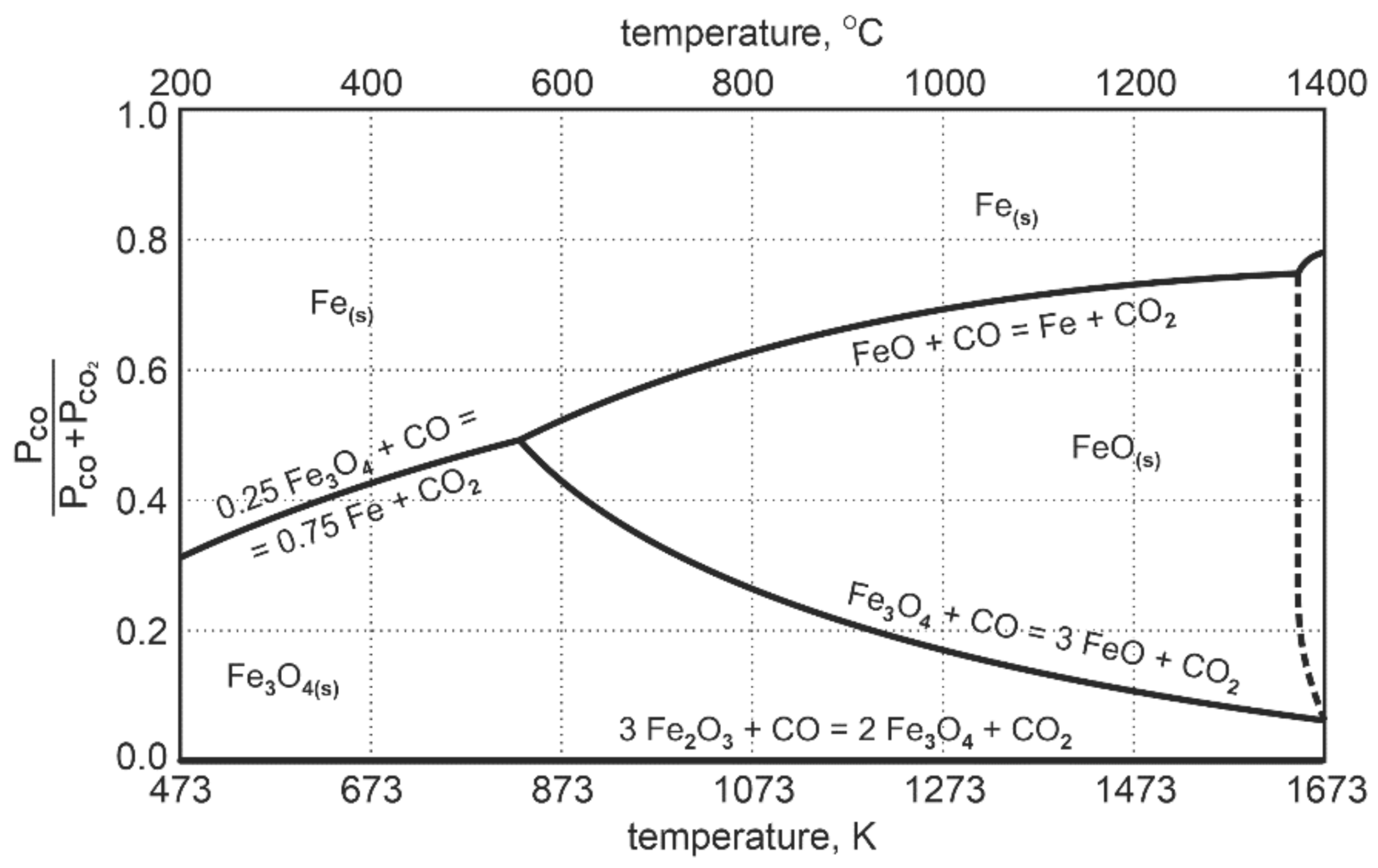
The diagram in
Figure 2 presenting the Fe-O-C equilibrium system shows that at the temperature of 1000 °C, only about 30% of CO is used for the reduction reaction of FeO to Fe
met. After that, the system reaches a state of equilibrium.
This means that about 70% by mole volume of CO is chemically inactive towards FeO. The process of reduction to metallic iron reached the level of 30%. In order to achieve full reduction of FeO to metallic iron, the reducing agent in the system should exceed the amount of:
where n—excessive of CO reducer required for complete reduction of FeO to metallic iron, %CO
2—equilibrium concentration of CO
2 in the system at a given temperature, expressed in percent.
For a temperature of 1000 °C, the equation indicates that the excess should be 100/30 = 3.33 of the quantity received from the stoichiometric calculations. Difficulties connected with the exceeding value cease to be significant when the carbon C is present in the system; then the coal gasification reaction (Boudouard reaction) occurs according to the stoichiometric equation [
24]:
Depending on the carbon reactivity, the complete reaction and the total usage of CO
2 in the system occurs in the temperature range of 950 ÷ 1000 °C. Under such conditions in the system, CO
2 is reconstituted into CO, therefore the gas phase composition still has sufficient potential to reduce FeO to metallic iron. This form of reduction by carbon with the formation of CO is called direct reduction [
24]:
For the reduction temperature range of 900 ÷ 1050 °C, assumed in this research, the reduction process will take place—both, in the area of mixed and direct reduction. Special advantages of this type of reduction are that there is no need for a large excess of carbon monoxide and that the energy consumption of the entire reduction process is reduced due to the limitation of the scope of direct reduction—the Boudouard reaction is highly energy-consuming.
For a detailed determination of the equilibrium conditions for oxidation-reduction processes in the Fe-C-O and Fe-O-H system for the determined temperature range, computations were performed with the FactSage software package.
Table 9 shows the equilibrium gas composition depending on the temperature.
Figure 3 indicates a diagram of the concentration of gaseous reduction products in the temperature range of 850 ÷ 1050 °C.
The course of the equilibrium curves in
Figure 3 demonstrates that, as the temperature level increases, the degree of oxidation of the carbon monoxide reduction potential, playing the role of the reducing agent, decreases. Within the designated reduction temperature range of 850 ÷ 1050 °C, the content of equilibrium carbon dioxide as a gaseous product of FeO reduction decreases from 32.55 vol.% to 26.87 vol.%. For hydrogen acting as a reducing agent, the equilibrium curves of the Fe-O reduction demonstrate that an increase in the reduction temperature causes a greater hydrogen consumption in the reduction process. Within the temperature range of 850 ÷ 1050 °C, the equilibrium potential of H
2O is in the range of 34.17 ÷ 40.19 vol.%. Comparing the properties of the reducers according to the degree of their application in terms of reduction abilities, it can be noticed that at the temperature of 1050 °C the reduction process carried out with the use of hydrogen has an approx. 1.5 times greater reduction potential than the reduction carried out with the use of carbon monoxide.
The research tests were performed with the use of two types of gas reducers: pure carbon monoxide and a gas mixture of 50% CO + 50% H2. The amount of reducer was calculated taking into account the chemical composition of waste, the equilibrium conditions for the temperature of 1000 °C, and the reducer excess in the amount of 30% in relation to the amount theoretically necessary for reduction. The flow rate of the reducer was determined from the calculated amount of the reducer and the reduction time of 180 min (this does not apply to additional experiments with a deliberately increased amount of reducer).
When using carbon monoxide, the reduction process was determined continuously, using an automated analysis of CO and CO2 in the ABB Uras 14 gas analyzer. This analyzer is part of the Laboratory at the Department of Metallurgy and Metal Technology at the Częstochowa University of Technology. Thus, when using the mixture of CO and H2, the course of the reduction was observed and the amount of water condensing from the post-reaction gases was periodically recorded. After the reduction process, all samples were subject to chemical analysis for the content of total iron (Fet) and metallic iron (Femet.). Furthermore, on selected samples, a structural analysis was performed for the content of metallic iron and other iron phases and compounds.


