
Influence of the 6061 Aluminium Alloy Thermo-Viscoplastic Behaviour on the Load-Area Relation of a Contact


Abstract

1. Introduction
2. Materials and Methods
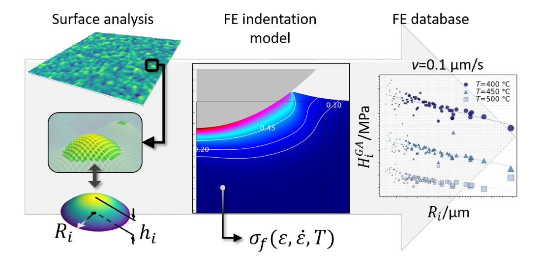
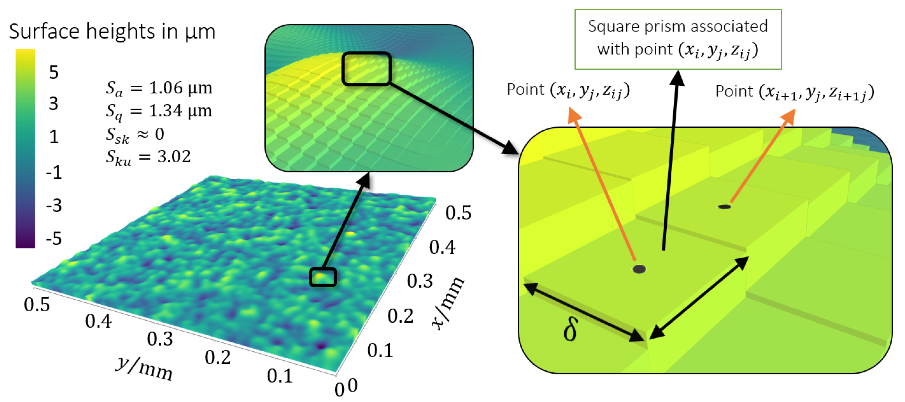
2.1. Topography and Representation
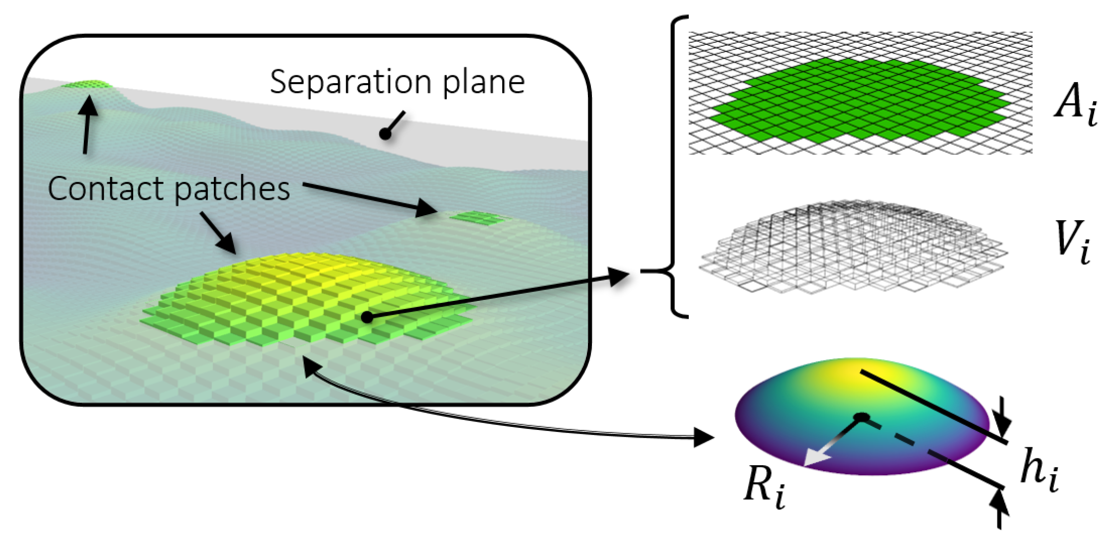
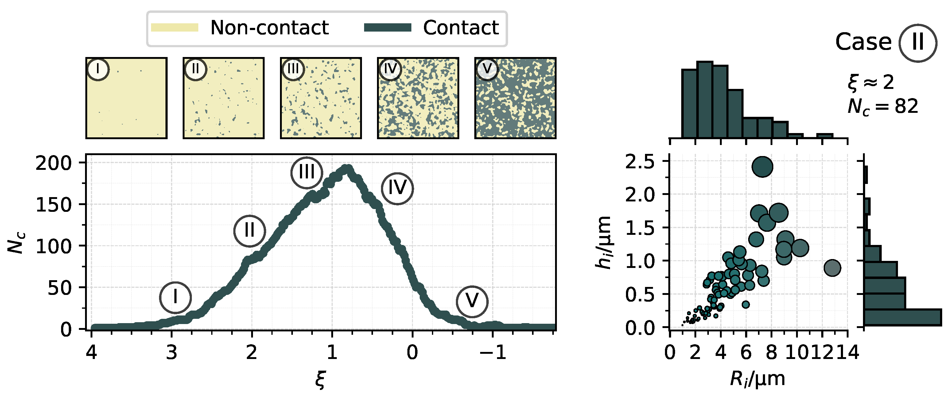
2.2. Degree of Separation
 is detailed.
 , detailed in Figure 3. At such a separation, a noticeable number of diversely shaped contact patches are resolved and it is reasonably assumed that other effects, such as the bulk deformation, or the presence of a lubricant did not play a major role in the contact yet.
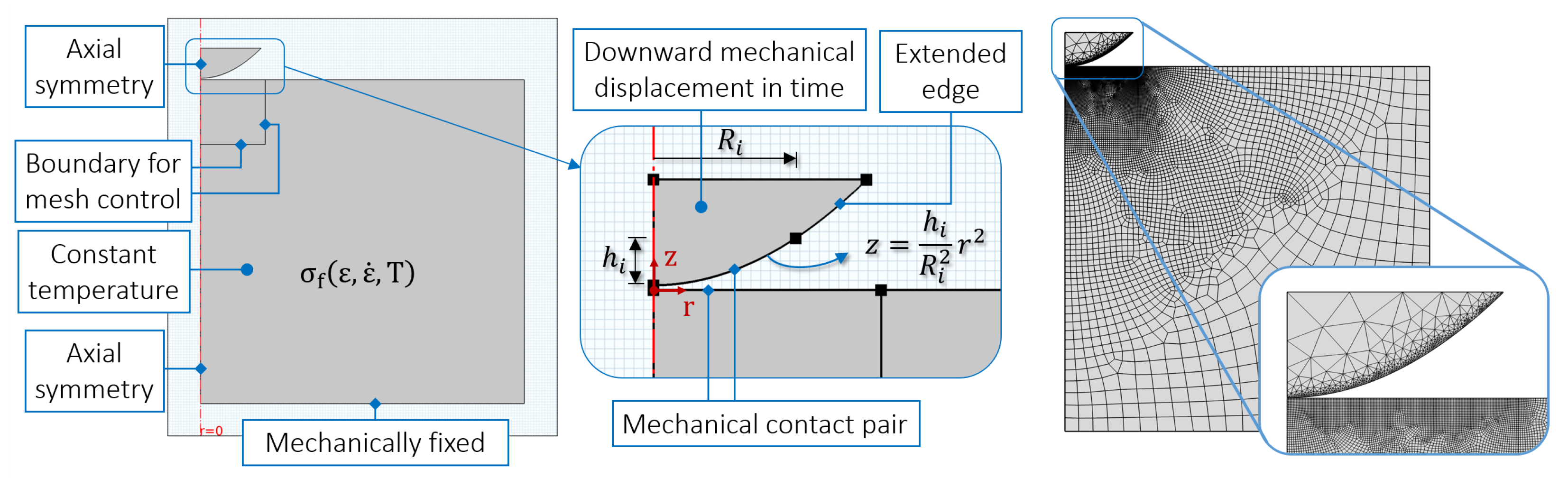
2.3. Single Asperity Finite Element Model
2.4. Material Models
3. Results and Discussion
3.1. Asperity
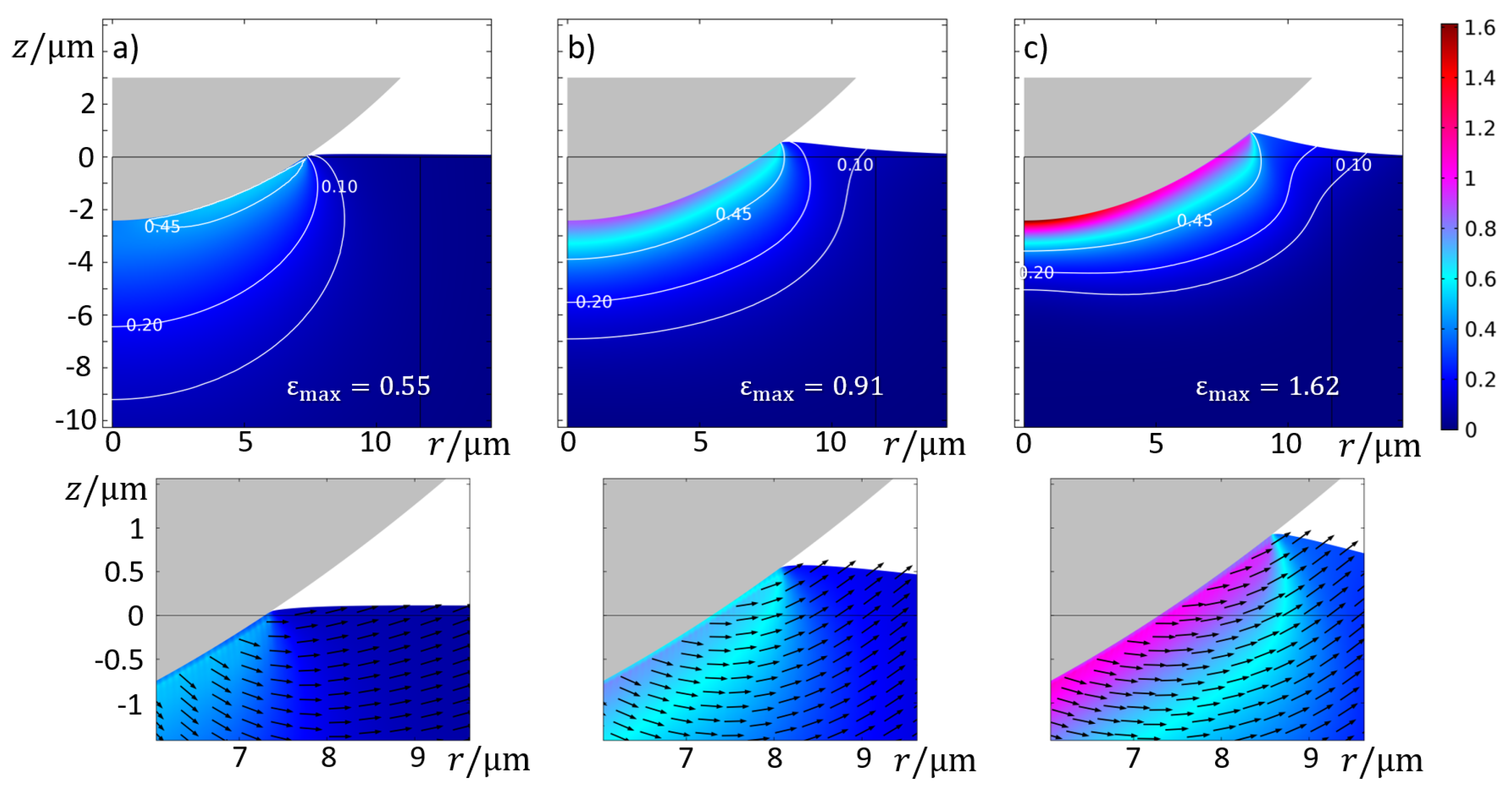
3.1.1. Strain, Strain Rate, and Temperature
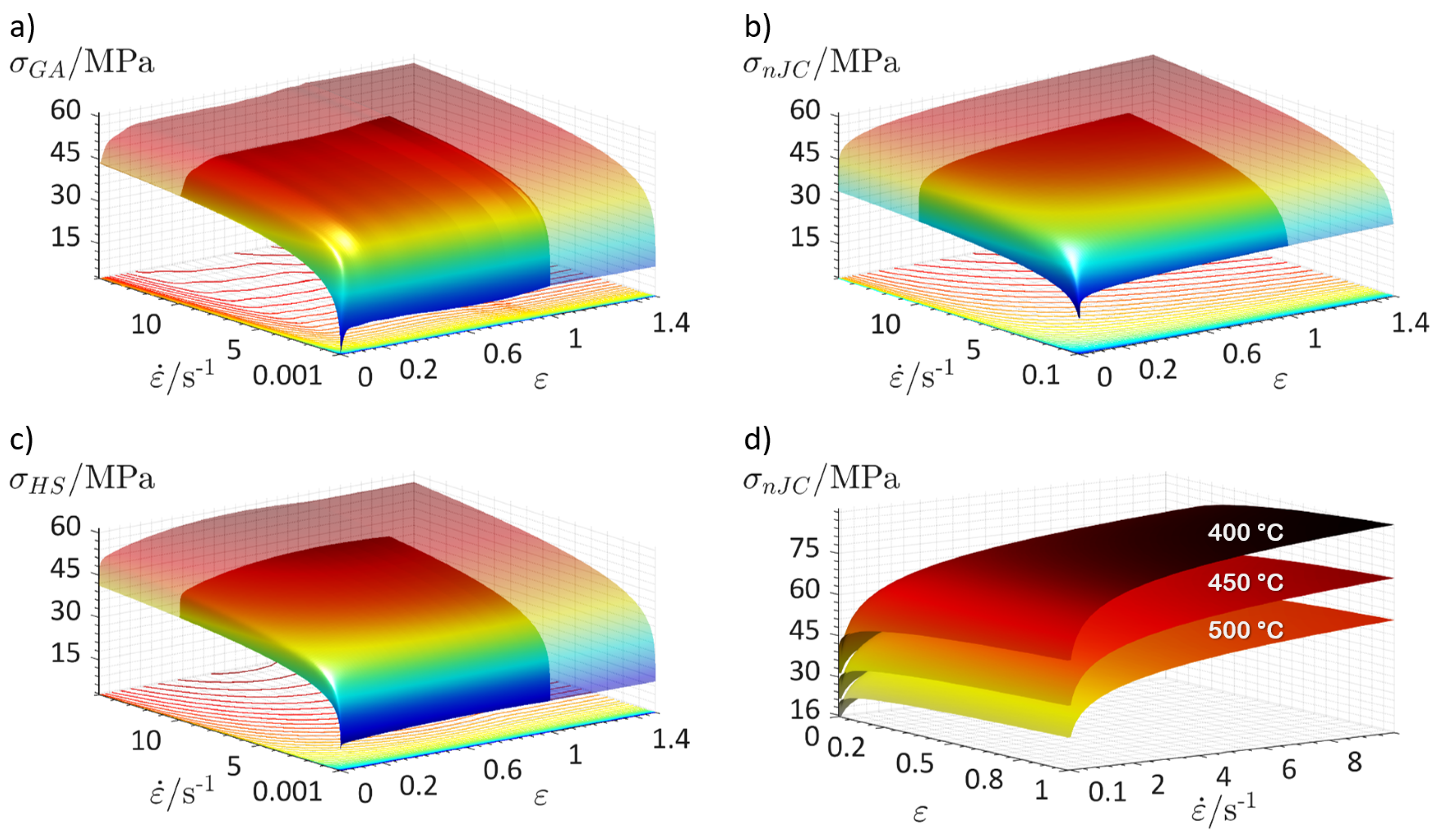
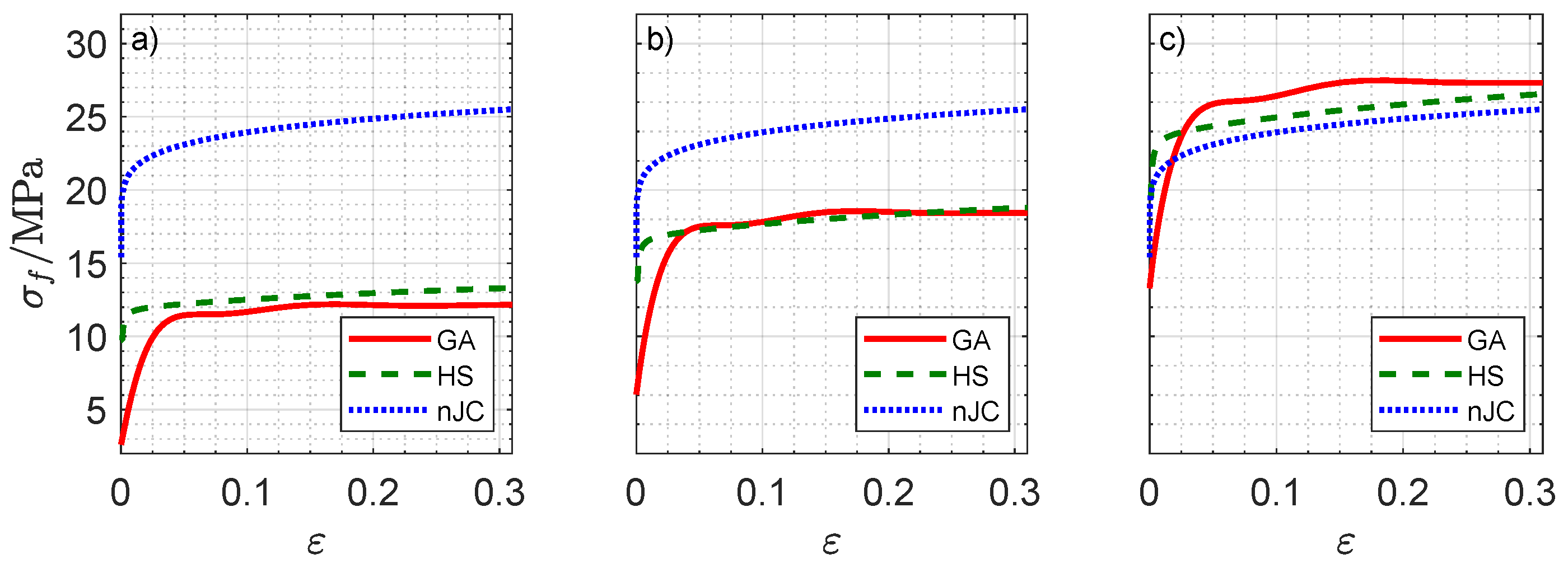
3.1.2. Material Model
3.2. Surface
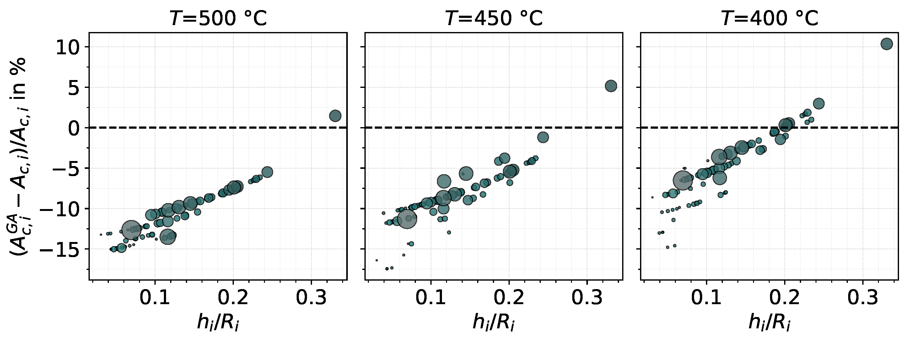
 (Figure 3). For this goal, the database of the GA model is used. As discussed previously, may deviate from consequently causing the total contact area from the FE database to deviate from that calculated by the surface algorithm. In Figure 15, the database contact area of each asperity, , is compared to that given by Equation (6), in terms of a relative difference plotted against the aspect ratio .
4. Conclusions
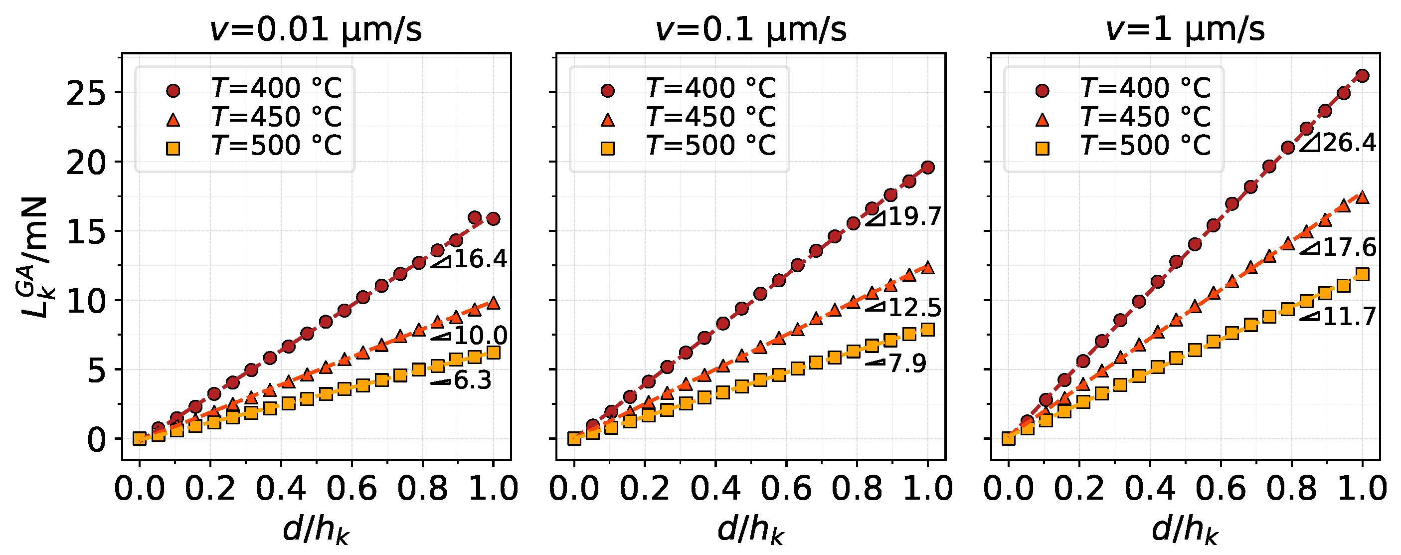
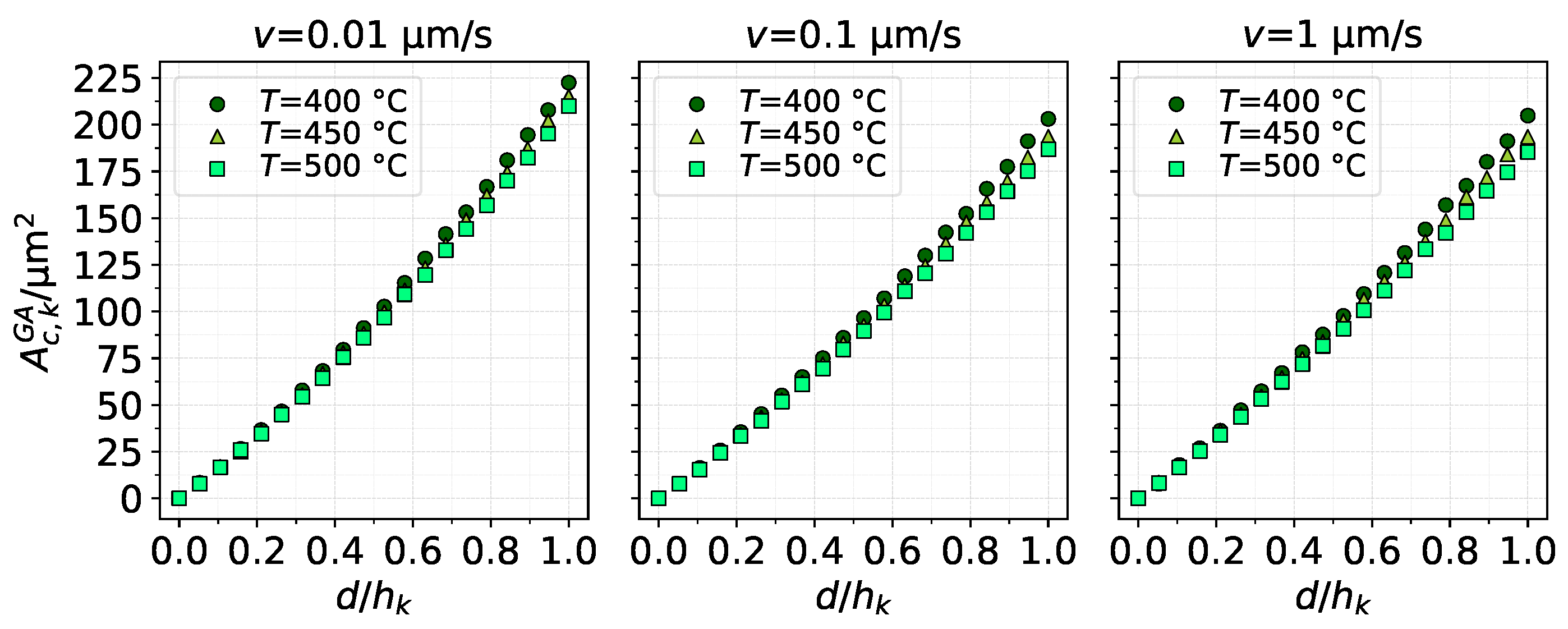
- The thermo-viscoplastic parameters of the indented material had a clear influence on contact load, contact area, average pressure, and pile-up/sink-in. Despite the nonlinear nature of the material model, load and contact area of a single asperity showed a fairly linear behaviour with indentation depth whereas average pressure tended to decrease slightly after reaching a maximum at the start of contact.
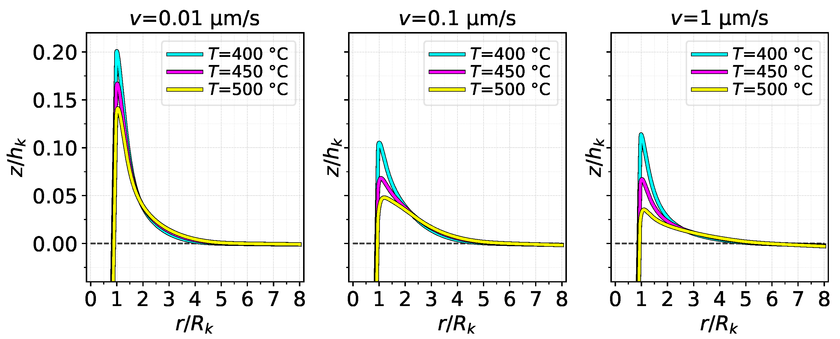
- The movement of the initially non-contacting region, i.e., the sink-in/pile-up behaviour, affects the contact area computation and is significantly dependent on the thermo-viscoplastic conditions and choice of material model.
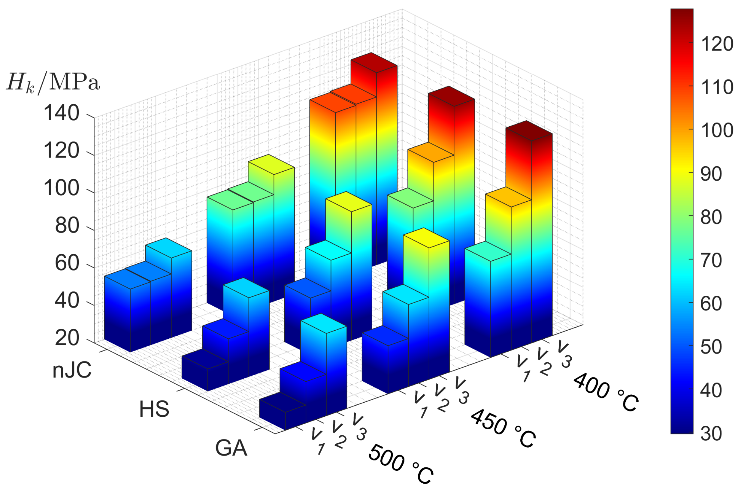
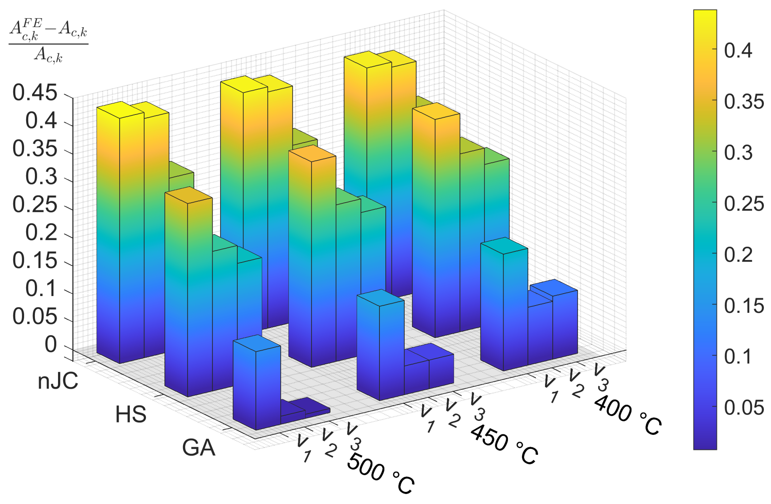
- Strain rate effects at very small strain rates significantly affected contact load and contact area calculation, as evidenced by the comparisons between different material models and particularly the nJC model. Overall, the choice of the material model had more pronounced effects on area computations than on contact load.
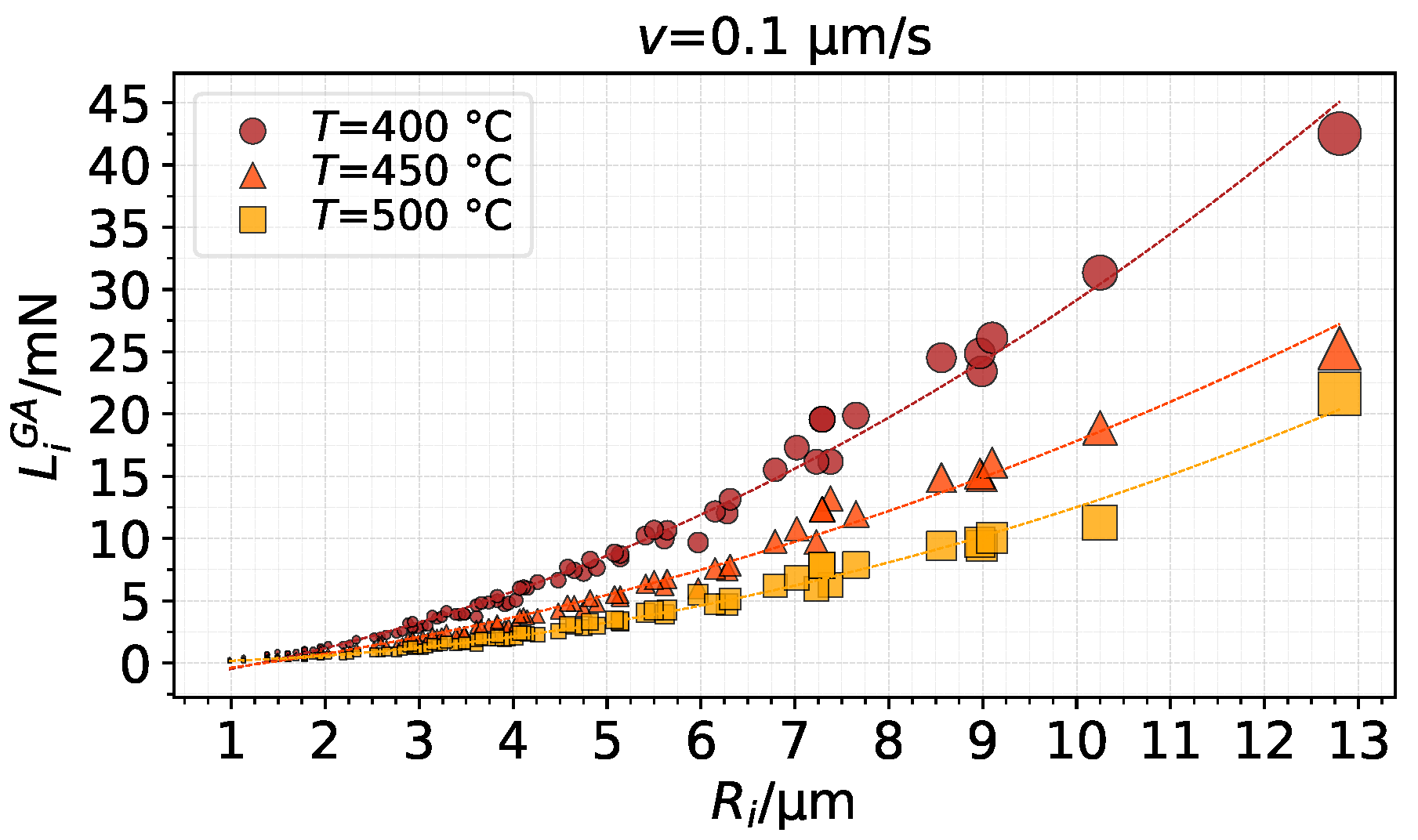
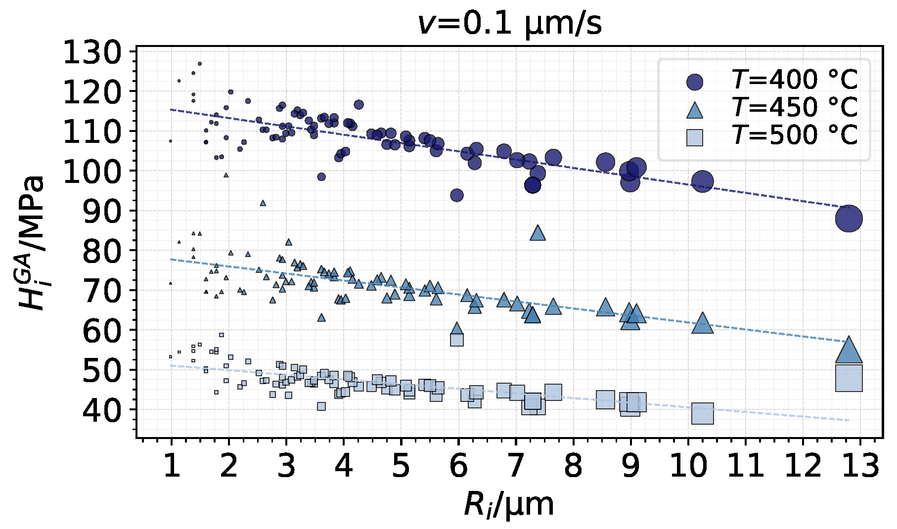
- Simulations of diversely shaped asperities showed a quadratic dependence of the contact load on the radius of the asperity. Nonetheless, asperities with smaller radii supported more pressure than asperities with bigger radii.
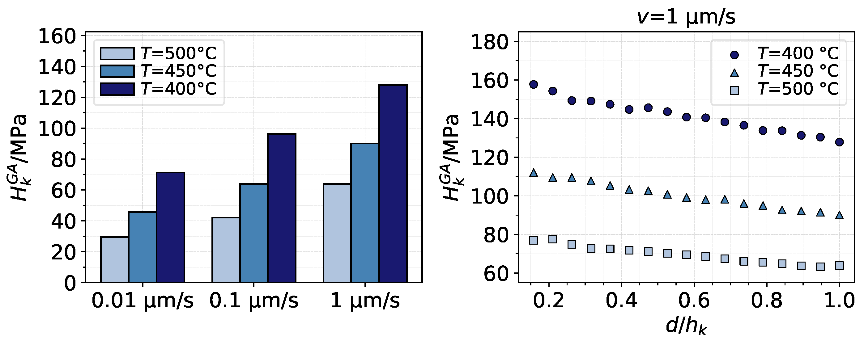
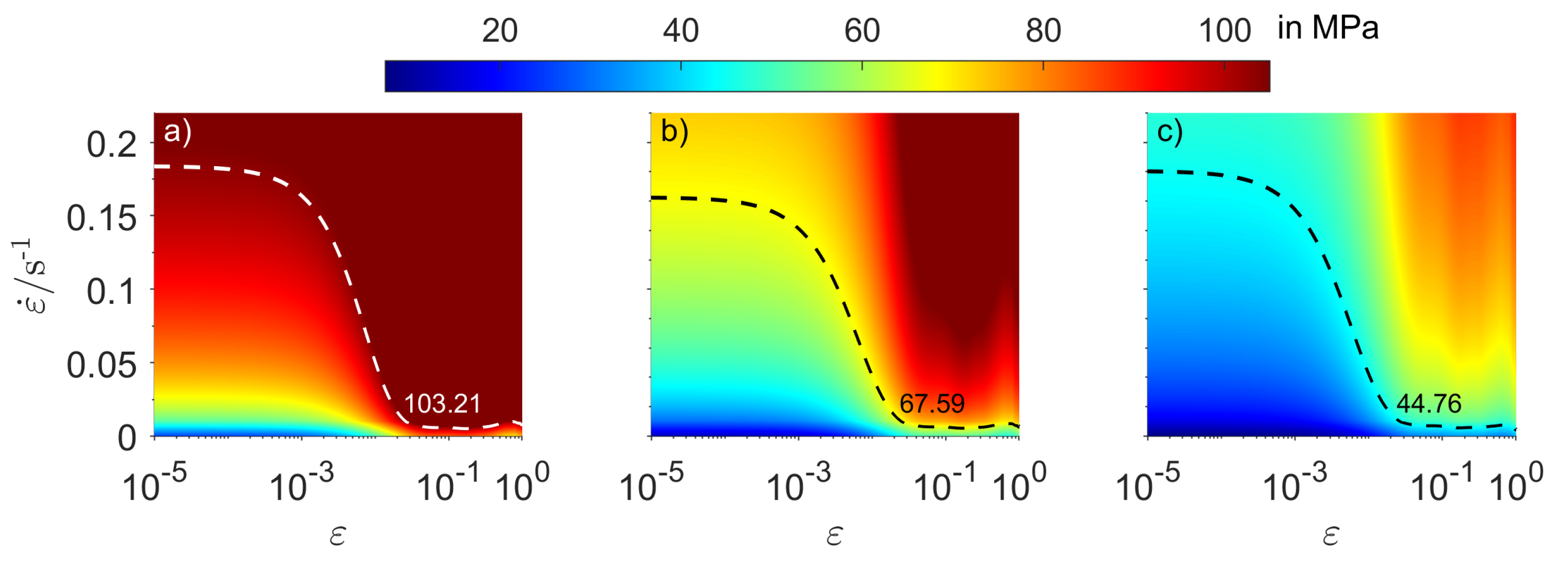
- The use of an equivalent hardness value for a fully plastic contact model should be obtained by evaluating the thermo-viscoplastic flow stress at nonzero values of strain and strain rate depending on the temperature.
Author Contributions
Funding
Institutional Review Board Statement
Informed Consent Statement
Data Availability Statement
Conflicts of Interest
List of Symbols
| Surface area of general paraboloid-represented contact patch i (or simply | |
| “asperity i”) | |
| Surface area of paraboloid-represented contact patch k (or simply “asperity k”) | |
| Contact area of asperity i and k, respectively, from FE simulation | |
| Contact area of asperity i and k, respectively, from FE simulation using the | |
| GA model | |
| HS model material constants | |
| Base area of contact patch i | |
| Nominal contact area | |
| nJC model material constants | |
| Real contact area | |
| c | Constraint factor |
| d | Indentation depth |
| DET | Abbreviation: Distortion-energy theory |
| FE | Abbreviation: Finite Element |
| GA | Abbreviation: Garofalo-Arrhenius |
| HS | Abbreviation: Hensel-Spittel |
| H | Indentation hardness |
| Equivalent hardness | |
| Height of general paraboloid-represented contact patch i (or simply “asperity i”) | |
| Height of paraboloid-represented contact patch k (or simply “asperity k”) | |
| Average contact pressure of asperity k |
| Average contact pressure of asperity k from FE simulation using the GA model | |
| L | Total normal load |
| Vertical contact load caused by asperity k from FE simulation using the GA model | |
| Number of contact patches at separation | |
| Number of surface heights that belong to contact patch i | |
| nJC | Abbreviation: new Johnson-Cook |
| Nominal pressure | |
| R | Universal gas constant |
| Radius of general paraboloid-represented contact patch i (or simply “asperity i”) | |
| Radius of paraboloid-represented contact patch k (or simply “asperity k”) | |
| s | Surface separation |
| Arithmetical mean height | |
| Kurtosis | |
| Root mean square height | |
| Skewness | |
| T | Temperature |
| Reference deformation temperature | |
| v | Indentation velocity of asperity |
| Indentation velocities | |
| Volume of contact patch i | |
| Surface points coordinates in Cartesian coordinates system | |
| Spatial coordinates in axisymmetric coordinates system | |
| GA model material constants | |
| Side length of square pixel and of square prism base | |
| Distance between surface points in plane | |
| Equivalent plastic strain and maximum equivalent palstic strain | |
| Equivalent plastic strain rate | |
| Dimensionless strain rate for nJC model | |
| Reference strain rate for nJC model | |
| Flow stress, yield stress, and von Mises stress | |
| Flow stress predicted by GA, HS, and nJC models, respectively | |
| Dimensionless separation |
Appendix A

| - | - | ||
| - | - |
References
- Valigi, M.; Logozzo, S.; Affatato, S. New Challenges in Tribology: Wear Assessment Using 3D Optical Scanners. Materials 2017, 10, 548. [Google Scholar] [CrossRef] [PubMed]
- Vakis, A.; Yastrebov, V.; Scheibert, J.; Nicola, L.; Dini, D.; Minfray, C.; Almqvist, A.; Paggi, M.; Lee, S.; Limbert, G.; et al. Modeling and simulation in tribology across scales: An overview. Tribol. Int. 2018, 125, 169–199. [Google Scholar] [CrossRef]
- Kurdi, A.; Alhazmi, N.; Alhazmi, H.; Tabbakh, T. Practice of Simulation and Life Cycle Assessment in Tribology—A Review. Materials 2020, 13, 3489. [Google Scholar] [CrossRef]
- Hsu, C.J.; Barrirero, J.; Merz, R.; Stratmann, A.; Aboulfadl, H.; Jacobs, G.; Kopnarski, M.; Mücklich, F.; Gachot, C. Revealing the interface nature of ZDDP tribofilm by X-ray photoelectron spectroscopy and atom probe tomography. Ind. Lubr. Tribol. 2020, 72, 923–930. [Google Scholar] [CrossRef]
- Faruck, A.A.M.; Hsu, C.J.; Doerr, N.; Weigand, M.; Gachot, C. How lubricant formulations and properties influence the performance of rotorcraft transmissions under loss of lubrication conditions. Tribol. Int. 2020, 151, 106390. [Google Scholar] [CrossRef]
- Göçerler, H.; Pfeil, B.; Franek, F.; Bauer, C.; Niculescu-Morzsa, E.; Nehrer, S. The dominance of water on lubrication properties of articular joints. Ind. Lubr. Tribol. 2019, 72, 31–37. [Google Scholar] [CrossRef]
- Varga, M.; Leroch, S.; Eder, S.J.; Rojacz, H.; Ripoll, M.R. Influence of velocity on high-temperature fundamental abrasive contact: A numerical and experimental approach. Wear 2019, 426-427, 370–377. [Google Scholar] [CrossRef]
- Vrček, A.; Hultqvist, T.; Johannesson, T.; Marklund, P.; Larsson, R. Micro-pitting and wear characterization for different rolling bearing steels: Effect of hardness and heat treatments. Wear 2020, 458-459, 203404. [Google Scholar] [CrossRef]
- Boidi, G.; da Silva, M.R.; Profito, F.J.; Machado, I.F. Using Machine Learning Radial Basis Function (RBF) Method for Predicting Lubricated Friction on Textured and Porous Surfaces. Surf. Topogr. Metrol. Prop. 2020, 8, 044002. [Google Scholar] [CrossRef]
- Varga, M.; Leroch, S.; Gross, T.; Rojacz, H.; Eder, S.; Grillenberger, M.; Ripoll, M.R. Scratching aluminium alloys–Modelling and experimental assessment of damage as function of the strain rate. Wear 2021, 203670. [Google Scholar] [CrossRef]
- Schey, J. Tribology in Metalworking: Friction, Lubrication, and Wear; Number Bd. 1; American Society for Metals: Cleveland, OH, USA, 1983; ISBN 9780871701558. [Google Scholar]
- Bettscheider, S.; Gachot, C.; Rosenkranz, A. How to measure the real contact area? A simple marker and relocation foot-printing approach. Tribol. Int. 2016, 103, 167–175. [Google Scholar] [CrossRef]
- Garofalo, F. Fundamentals of Creep and Creep-Rupture in Metals; Macmillan: New York, NY, USA, 1965; p. 258. [Google Scholar]
- Totten, G.E.; MacKenzie, D.S. (Eds.) Handbook of Aluminum; CRC Press: Boca Raton, FL, USA, 2003. [Google Scholar] [CrossRef]
- Rudnytskyj, A.; Simon, P.; Jech, M.; Gachot, C. Constitutive modelling of the 6061 aluminium alloy under hot rolling conditions and large strain ranges. Mater. Des. 2020, 190, 108568. [Google Scholar] [CrossRef]
- Tabor, D. The Hardness of Metals; Oxford University Press: Hong Kong, 1951. [Google Scholar]
- Bowden, F.P.; Tabor, D. The area of contact between stationary and moving surfaces. Proc. R. Soc. Lond. Ser. A Math. Phys. Sci. 1939, 169, 391–413. [Google Scholar] [CrossRef]
- Bowden, F.P.; Moore, A.J.W.; Tabor, D. The Ploughing and Adhesion of Sliding Metals. J. Appl. Phys. 1943, 14, 80–91. [Google Scholar] [CrossRef]
- Masen, M.; de Rooij, M. Abrasive wear between rough surfaces in deep drawing. Wear 2004, 256, 639–646. [Google Scholar] [CrossRef][Green Version]
- Ma, X.; de Rooij, M.; Schipper, D. A load dependent friction model for fully plastic contact conditions. Wear 2010, 269, 790–796. [Google Scholar] [CrossRef]
- Torres, H.; Varga, M.; Ripoll, M.R. High temperature hardness of steels and iron-based alloys. Mater. Sci. Eng. A 2016, 671, 170–181. [Google Scholar] [CrossRef]
- Hol, J.; Alfaro, M.C.; Meinders, T.; Huétink, J. Advanced Friction Modeling in Sheet Metal Forming. Key Eng. Mater. 2011, 473, 715–722. [Google Scholar] [CrossRef]
- Hol, J.; Meinders, V.; de Rooij, M.; van den Boogaard, A. Multi-scale friction modeling for sheet metal forming: The boundary lubrication regime. Tribol. Int. 2015, 81, 112–128. [Google Scholar] [CrossRef]
- Mekicha, M.; de Rooij, M.; Jacobs, L.; Matthews, D.; Schipper, D. Experimental validation of contact models for cold-rolling processes. J. Mater. Process. Technol. 2020, 275, 116371. [Google Scholar] [CrossRef]
- Bhushan, B. Contact Mechanics of Rough Surfaces in Tribology: Single Asperity Contact. Appl. Mech. Rev. 1996, 49, 275–298. [Google Scholar] [CrossRef]
- Ghaednia, H.; Wang, X.; Saha, S.; Xu, Y.; Sharma, A.; Jackson, R.L. A Review of Elastic–Plastic Contact Mechanics. Appl. Mech. Rev. 2017, 69. [Google Scholar] [CrossRef]
- Greenwood, J.A.; Williamson, J.P. Contact of nominally flat surfaces. Proc. R. Soc. Lond. Ser. A Math. Phys. Sci. 1966, 295, 300–319. [Google Scholar] [CrossRef]
- Ramezani, M.; Ripin, Z.M. A friction model for dry contacts during metal-forming processes. Int. J. Adv. Manuf. Technol. 2010, 51, 93–102. [Google Scholar] [CrossRef]
- Goedecke, A.; Mock, R. Creep Behavior of an Asperity in Fully Plastic Contact. Friction Wear Wear Prot. 2011, 307–313. [Google Scholar] [CrossRef]
- Liu, M.; Proudhon, H. Finite element analysis of frictionless contact between a sinusoidal asperity and a rigid plane: Elastic and initially plastic deformations. Mech. Mater. 2014, 77, 125–141. [Google Scholar] [CrossRef]
- Zhang, T.; Jiang, F.; Yan, L.; Xu, X. FEM Modeling of the Relationship between the High-Temperature Hardness and High-Temperature, Quasi-Static Compression Experiment. Materials 2017, 11, 34. [Google Scholar] [CrossRef]
- Trzepiecinski, T.; Lemu, H.G. A Three-Dimensional Elastic-Plastic Contact Analysis of Vickers Indenter on a Deep Drawing Quality Steel Sheet. Materials 2019, 12, 2153. [Google Scholar] [CrossRef]
- Hultqvist, T.; Vrcek, A.; Marklund, P.; Prakash, B.; Larsson, R. Transient analysis of surface roughness features in thermal elastohydrodynamic contacts. Tribol. Int. 2020, 141, 105915. [Google Scholar] [CrossRef]
- Shisode, M.; Hazrati, J.; Mishra, T.; de Rooij, M.; van den Boogaard, A. Semi-analytical contact model to determine the flattening behavior of coated sheets under normal load. Tribol. Int. 2020, 146, 106–182. [Google Scholar] [CrossRef]
- Aluminum Association, Inc. Rolling Aluminum: From the Mine Through the Mill; Technical Report; The Aluminum Association, Inc.: Arlington, VA, USA, 2007. [Google Scholar]
- Liewald, M.; Wagner, S.; Becker, D. Influence of Surface Topography on the Tribological Behaviour of Aluminium Alloy 5182 with EDT Surface. Tribol. Lett. 2010, 39, 135–142. [Google Scholar] [CrossRef]
- Hilgenberg, K.; Steinhoff, K. Texturing of skin-pass rolls by pulsed laser dispersing. J. Mater. Process. Technol. 2015, 225, 84–92. [Google Scholar] [CrossRef]
- Gonçalves, J.L.; de Mello, J.D.B.; Costa, H.L. Wear in cold rolling milling rolls: A methodological approach. Wear 2019, 426–427, 1523–1535. [Google Scholar] [CrossRef]
- Prajapati, D.K.; Tiwari, M. Topography Analysis of Random Anisotropic Gaussian Rough Surfaces. J. Tribol. 2017, 139. [Google Scholar] [CrossRef]
- Random Gaussian Surface Generation. Available online: https://www.mathworks.com/matlabcentral/answers/218806-random-gaussian-surface-generation. (accessed on 1 October 2020).
- Stoyanov, P.; Chromik, R.R. Scaling Effects on Materials Tribology: From Macro to Micro Scale. Materials 2017, 10, 550. [Google Scholar] [CrossRef]
- Greenwood, J.A. A note on Nayak’s third paper. Wear 2007, 262, 225–227. [Google Scholar] [CrossRef]
- van der Walt, S.; Schönberger, J.L.; Nunez-Iglesias, J.; Boulogne, F.; Warner, J.D.; Yager, N.; Gouillart, E.; Yu, T. scikit-image: Image processing in Python. PeerJ 2014, 2, e453. [Google Scholar] [CrossRef] [PubMed]
- Weisstein, E.W. Quadratic Surface. From MathWorld—A Wolfram Web Resource. Available online: https://mathworld.wolfram.com/QuadraticSurface.html (accessed on 10 September 2020).
- de Rooij, M.; van der Linde, G.; Schipper, D. Modelling material transfer on a single asperity scale. Wear 2013, 307, 198–208. [Google Scholar] [CrossRef]
- Wilson, W.; Sheu, S. Real area of contact and boundary friction in metal forming. Int. J. Mech. Sci. 1988, 30, 475–489. [Google Scholar] [CrossRef]
- Sutcliffe, M. Surface asperity deformation in metal forming processes. Int. J. Mech. Sci. 1988, 30, 847–868. [Google Scholar] [CrossRef]
- Spuzic, S.; Strafford, K.; Subramanian, C.; Savage, G. Wear of hot rolling mill rolls: An overview. Wear 1994, 176, 261–271. [Google Scholar] [CrossRef]
- Simon, P.; Falkinger, G.; Scheiblhofer, S. Hot Rolling Simulation of Aluminium Alloys using LS-Dyna. In Proceedings of the 11th European LS-DYNA Conference, Salzburg, Austria, 9–11 May 2017; Available online: https://www.dynalook.com/conferences/11th-european-ls-dyna-conference/process-hot-forming/hot-rolling-simulation-of-aluminium-alloys-using-ls-dyna (accessed on 3 September 2020).
- COMSOL Multiphysics® v. 5.2a. COMSOL AB. Available online: https://www.comsol.com/release/5.2a (accessed on 29 January 2021).
- Sönnerlind, H. What Is Geometric Nonlinearity? Available online: https://www.comsol.com/blogs/what-is-geometric-nonlinearity/ (accessed on 14 September 2020).
- Eid, H.; Adams, G.G. An Elastic-Plastic Finite Element Analysis of Interacting Asperity Contacts. In Proceedings of the STLE/ASME 2006 International Joint Tribology Conference, San Antonio, TX, USA, 23–25 October 2006; pp. 1469–1473. [Google Scholar] [CrossRef]
- Zener, C.; Hollomon, J.H. Effect of Strain Rate Upon Plastic Flow of Steel. J. Appl. Phys. 1944, 15, 22–32. [Google Scholar] [CrossRef]
- Sellars, C.; McTegart, W. On the mechanism of hot deformation. Acta Metall. 1966, 14, 1136–1138. [Google Scholar] [CrossRef]
- Slooff, F.; Zhou, J.; Duszczyk, J.; Katgerman, L. Constitutive analysis of wrought magnesium alloy Mg–Al4–Zn1. Scr. Mater. 2007, 57, 759–762. [Google Scholar] [CrossRef]


| MPa | |||||||
|---|---|---|---|---|---|---|---|
| 5179.35 | −0.006486 | 0.005376 | −0.228525 | −0.000186 | 0.001444 | −0.668259 | −0.000489 |
| MPa | MPa | n | C | ||
|---|---|---|---|---|---|
| 31.2161 | 24.3329 | 0.149543 | 0.140036 | −0.00705089 | 0.000489547 |
| 400 | 450 | 500 | |
|---|---|---|---|
| 5688.71 | 5437.45 | 5293.03 | |
| 587.14 | 367.5 | 236.99 | |
| 2.28% | 2.17% | 2.12% | |
| 103.21 | 67.59 | 44.76 |
Publisher’s Note: MDPI stays neutral with regard to jurisdictional claims in published maps and institutional affiliations. |
© 2021 by the authors. Licensee MDPI, Basel, Switzerland. This article is an open access article distributed under the terms and conditions of the Creative Commons Attribution (CC BY) license (http://creativecommons.org/licenses/by/4.0/).
Share and Cite
Rudnytskyj, A.; Krenn, S.; Vorlaufer, G.; Gachot, C. Influence of the 6061 Aluminium Alloy Thermo-Viscoplastic Behaviour on the Load-Area Relation of a Contact. Materials 2021, 14, 1352. https://doi.org/10.3390/ma14061352
Rudnytskyj A, Krenn S, Vorlaufer G, Gachot C. Influence of the 6061 Aluminium Alloy Thermo-Viscoplastic Behaviour on the Load-Area Relation of a Contact. Materials. 2021; 14(6):1352. https://doi.org/10.3390/ma14061352
Chicago/Turabian StyleRudnytskyj, André, Stefan Krenn, Georg Vorlaufer, and Carsten Gachot. 2021. "Influence of the 6061 Aluminium Alloy Thermo-Viscoplastic Behaviour on the Load-Area Relation of a Contact" Materials 14, no. 6: 1352. https://doi.org/10.3390/ma14061352
APA StyleRudnytskyj, A., Krenn, S., Vorlaufer, G., & Gachot, C. (2021). Influence of the 6061 Aluminium Alloy Thermo-Viscoplastic Behaviour on the Load-Area Relation of a Contact. Materials, 14(6), 1352. https://doi.org/10.3390/ma14061352