
The 3D-Printed Honeycomb Metamaterials Tubes with Tunable Negative Poisson’s Ratio for High-Performance Static and Dynamic Mechanical Properties

 ,
,
Abstract
1. Introduction
2. Samples, Quasi-Static, and Dynamic Loading Tests of the 3D-Printed CCHT
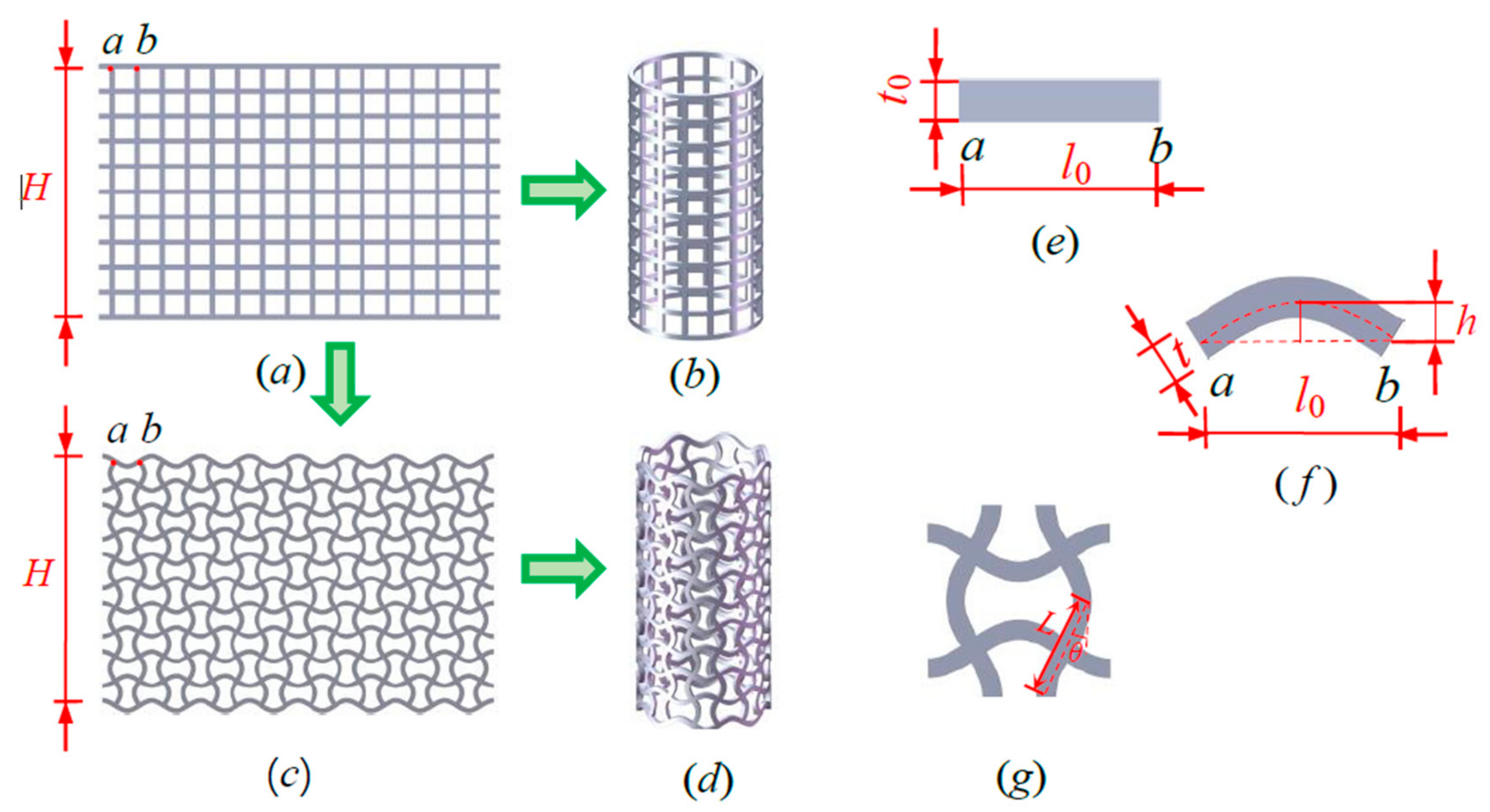
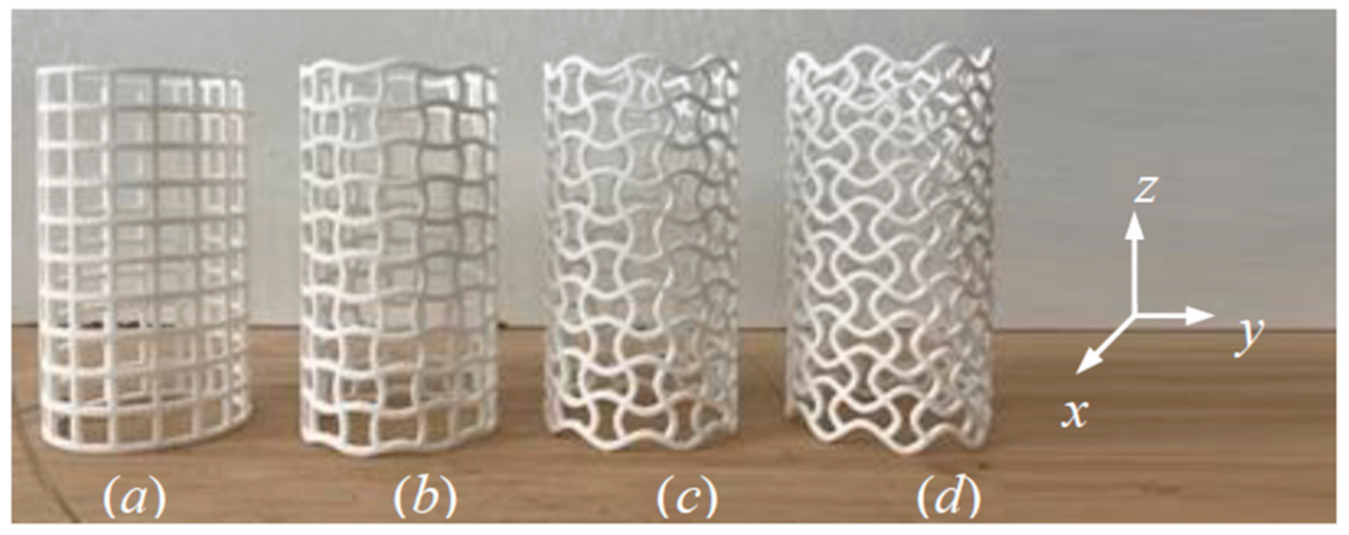
2.1. Geometric Topology and 3D-Printed Samples of the CCHT
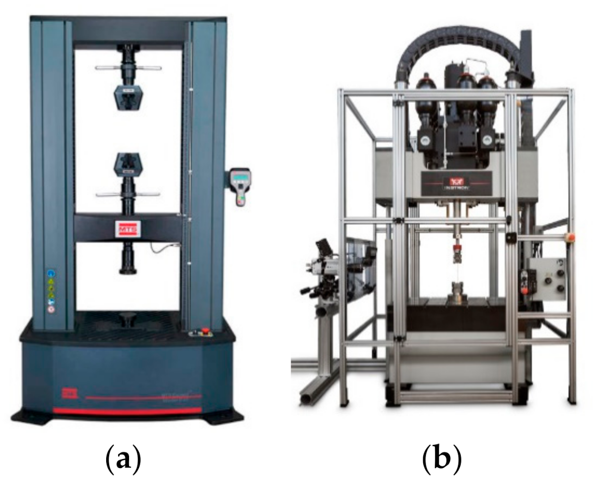
2.2. Quasi-Static and Dynamic Compressive Experiments Devices
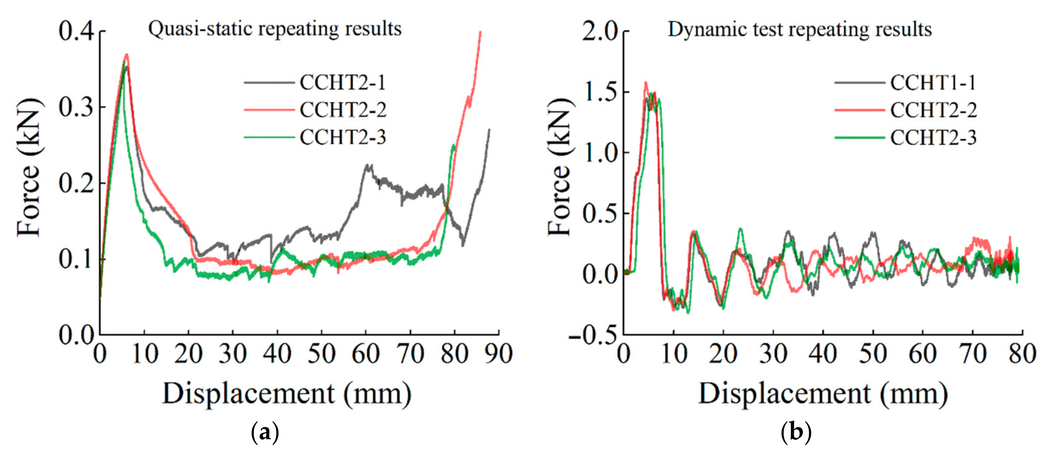
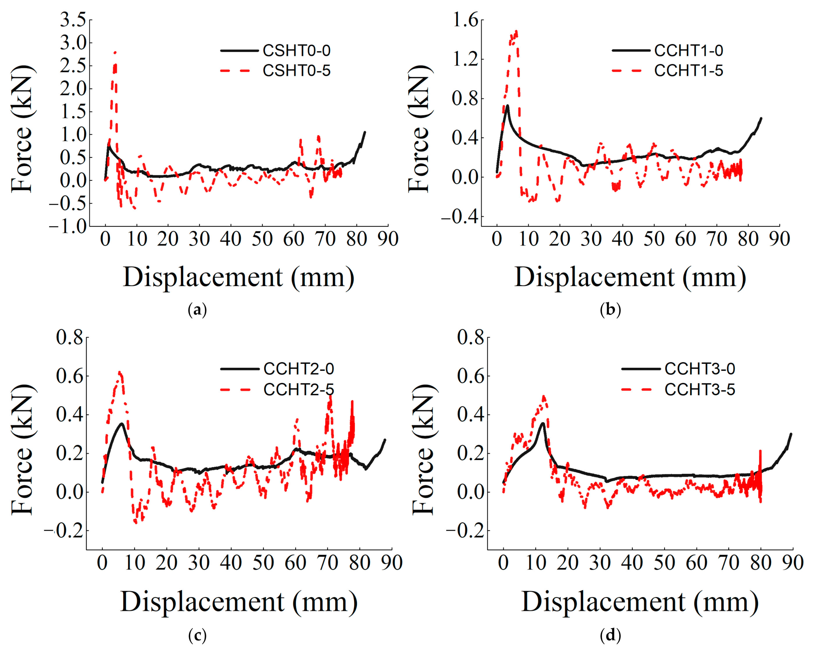
2.3. Repeatability of the Experimental Force–Displacement Curve
3. Mechanical Properties of the NPR CCHT under Static Loading Conditions
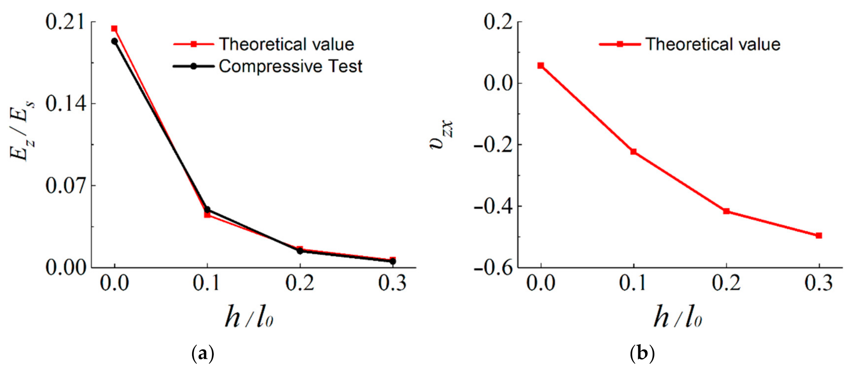
3.1. Effect of Geometrical Morphology on Elastic Moduli of the CCHT
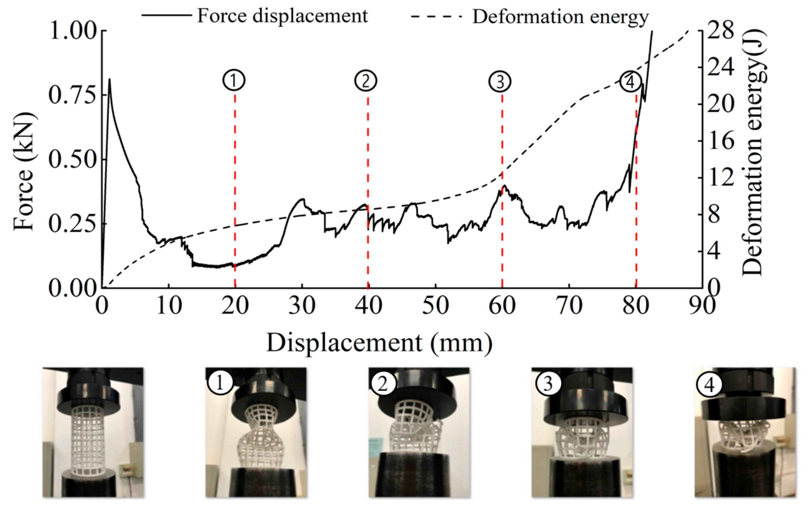
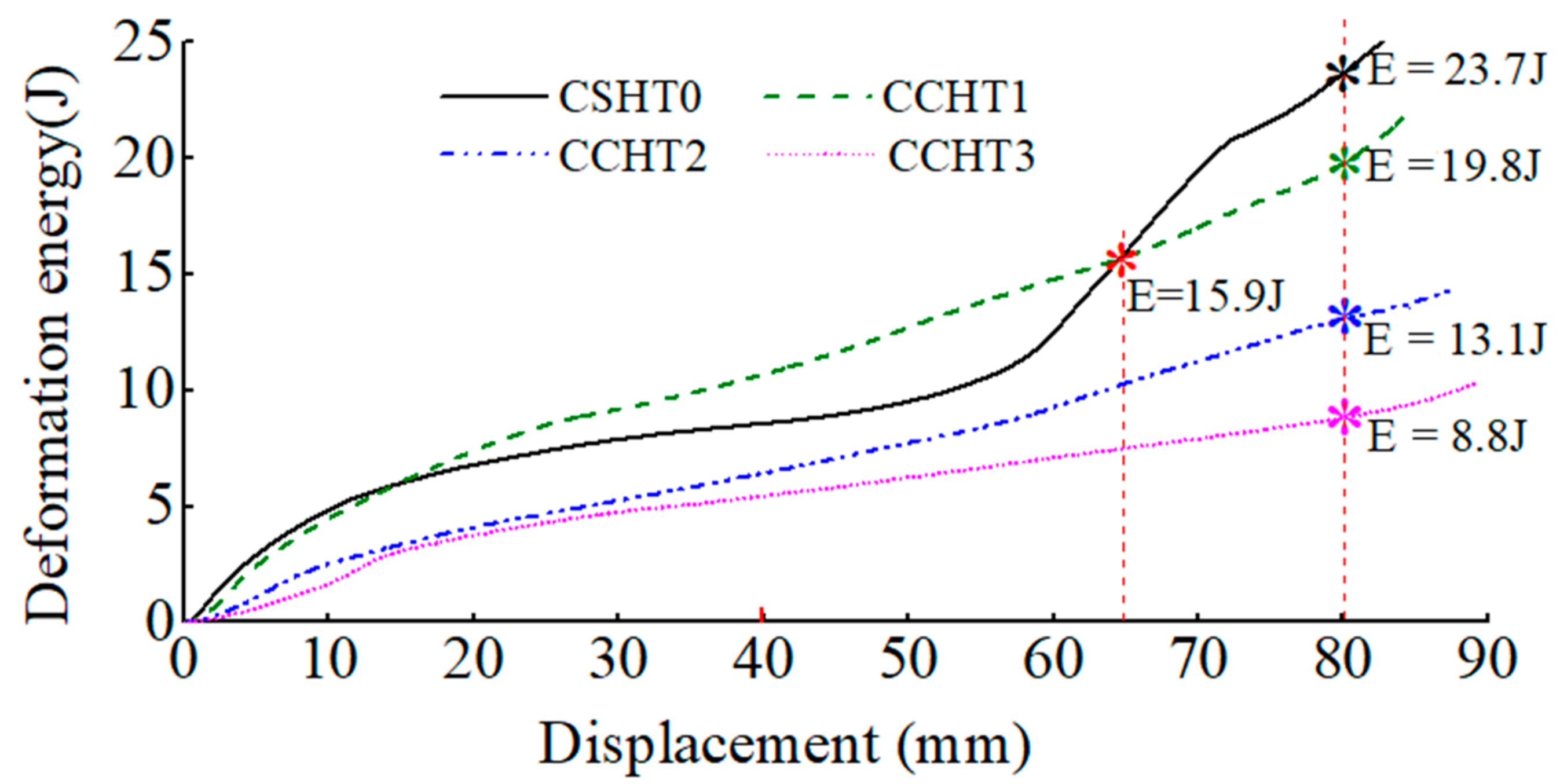
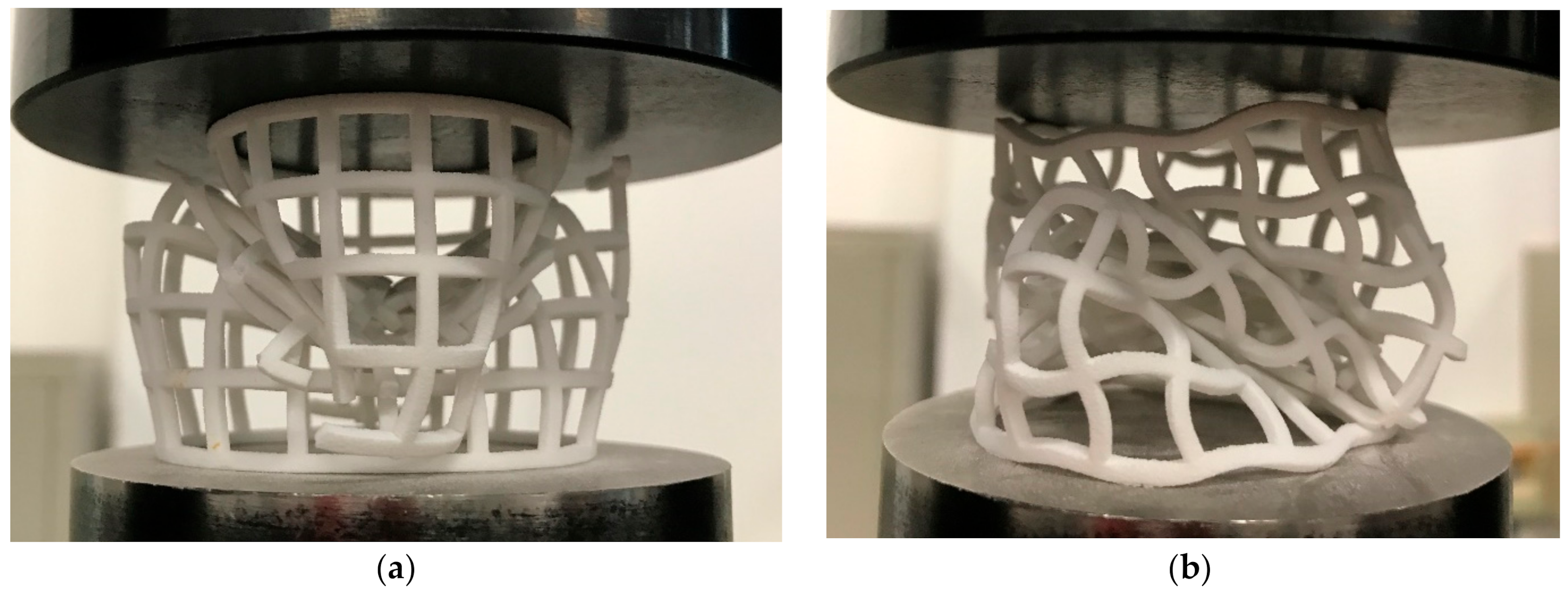
3.2. Damage Patterns and Energy Absorption Properties
4. Mechanical Properties of the NPR CCHT under Dynamic Loading Conditions
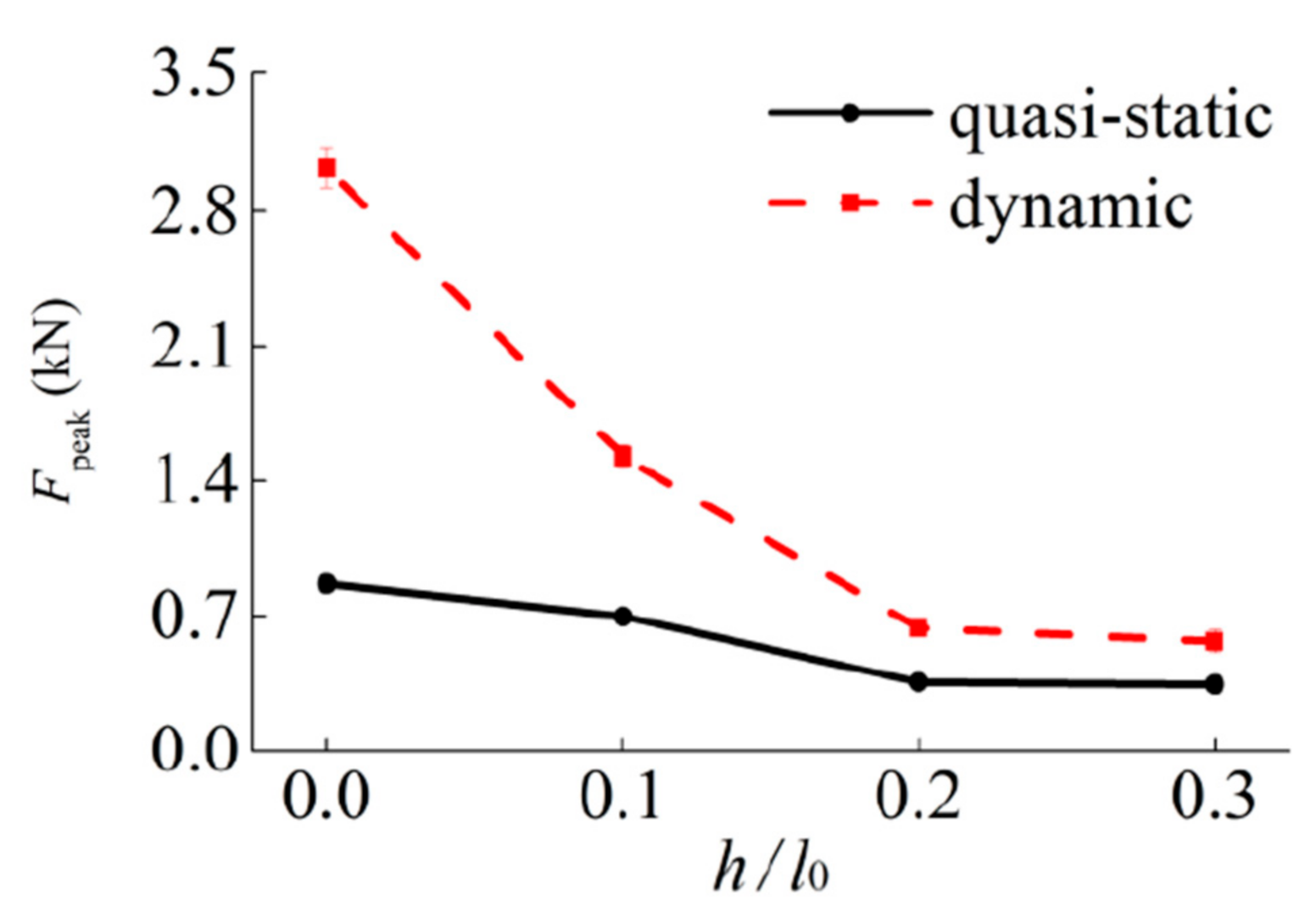
4.1. Dynamic Enhancement Analysis
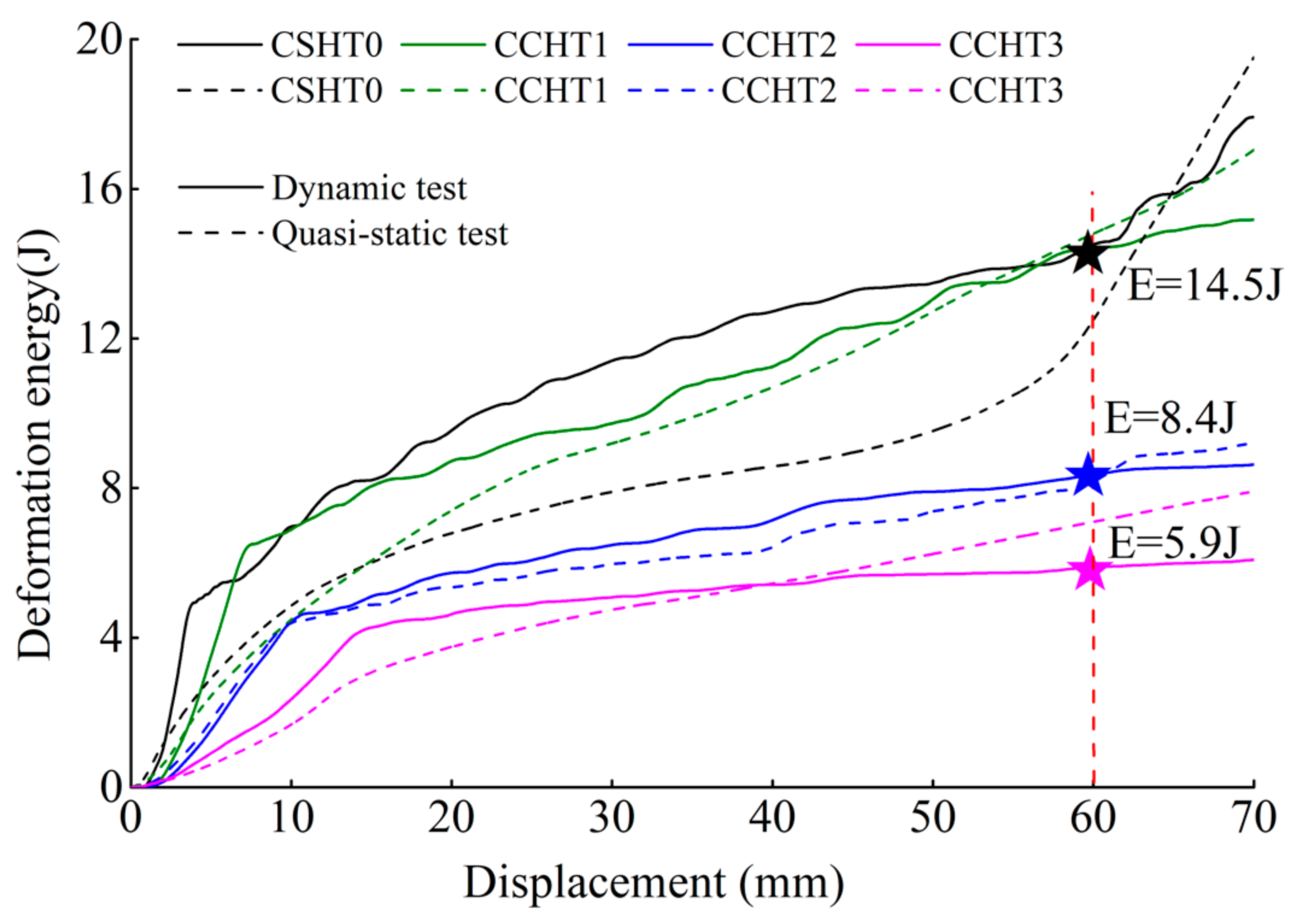
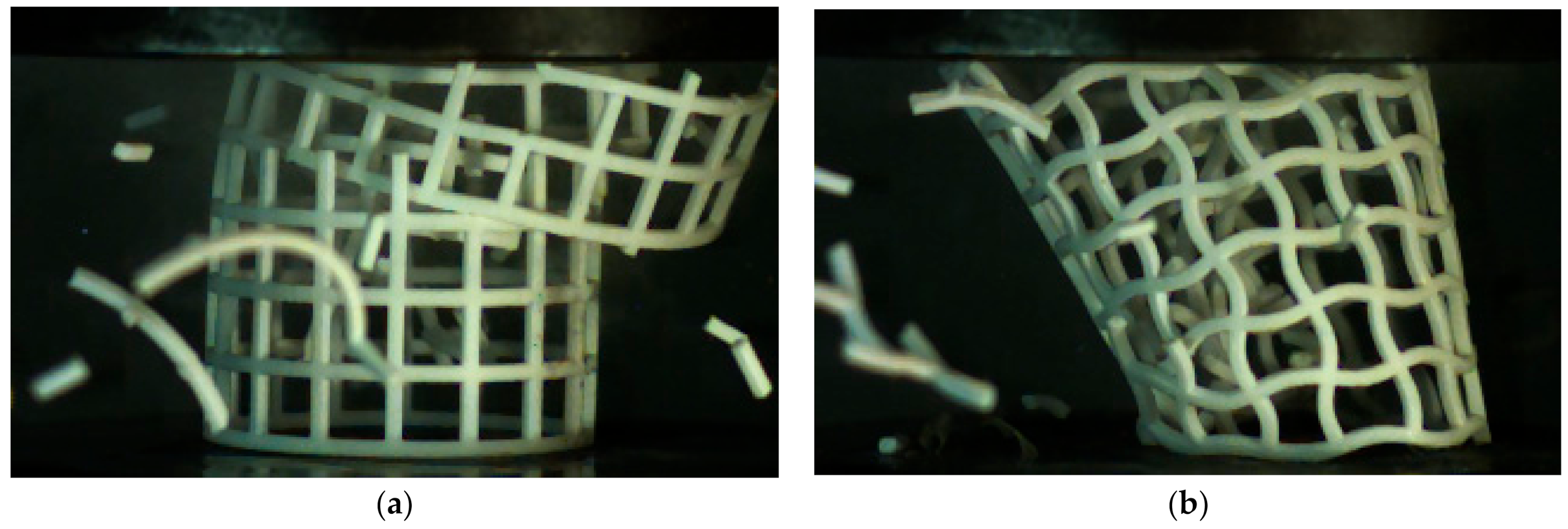
4.2. Damage Patterns and Energy Absorption Properties
5. Conclusions
Author Contributions
Funding
Institutional Review Board Statement
Informed Consent Statement
Data Availability Statement
Conflicts of Interest
References
- Lee, J.-H.; Singer, J.P.; Thomas, E.L. Micro-/Nanostructured Mechanical Metamaterials. Adv. Mater. 2012, 24, 4782–4810. [Google Scholar] [CrossRef]
- Shen, J.; Zhou, S.; Huang, X.; Xie, Y.M. Simple cubic three-dimensional auxetic metamaterials. Phys. Status Solidi B 2014, 251, 1515–1522. [Google Scholar] [CrossRef]
- Cui, S.; Gong, B.; Ding, Q.; Sun, Y.; Ren, F.; Liu, X.; Yan, Q.; Yang, H.; Wang, X.; Song, B. Mechanical Metamaterials Foams with Tunable Negative Poisson’s Ratio for Enhanced Energy Absorption and Damage Resistance. Materials 2018, 11, 1869. [Google Scholar] [CrossRef]
- Mizzi, L.; Mahdi, E.M.; Titov, K.; Gatt, R.; Attard, D.; Evans, K.E.; Grima, J.N. Mechanical metamaterials with star-shaped pores exhibiting negative and zero Poisson’s ratio. Mater. Des. 2018, 146, 28–37. [Google Scholar] [CrossRef]
- Yu, X.; Zhou, J.; Liang, H.; Jiang, Z.; Wu, L. Mechanical metamaterials associated with stiffness, rigidity and compressibility: A brief review. Prog. Mater. Sci. 2018, 94, 114–173. [Google Scholar] [CrossRef]
- Ning, S.; Yang, F.; Luo, C.; Liu, Z.; Zhuang, Z. Low-frequency tunable locally resonant band gaps in acoustic metamaterials through large deformation. Extrem. Mech. Lett. 2020, 35, 100623. [Google Scholar] [CrossRef]
- Li, X.; Ning, S.; Liu, Z.; Yan, Z.; Luo, C.; Zhuang, Z. Designing phononic crystal with anticipated band gap through a deep learning based data-driven method. Comput. Methods Appl. Mech. Eng. 2020, 361, 112737. [Google Scholar] [CrossRef]
- Dolla, W.J.S. Drug Diffusion and Structural Design Criteria for Conventional and Auxetic Stents; University of Missouri: Kansas City, MO, USA, 2006. [Google Scholar]
- Dolla, W.J.S.; Fricke, B.A.; Becker, B.R. Structural and drug diffusion models of conventional and auxetic drug-eluting stents. J. Med. Devices 2007, 1, 47–55. [Google Scholar] [CrossRef]
- Panico, M.; Langella, C.; Santulli, C. Development of a Biomedical Neckbrace through Tailored Auxetic Shapes. Ital. J. Sci. Eng. 2017, 1, 105–117. [Google Scholar] [CrossRef]
- Wang, Z.; Hu, H. Auxetic materials and their potential applications in textiles. Text. Res. J. 2014, 84, 1600–1611. [Google Scholar] [CrossRef]
- Hengelmolen, R. Auxetic Tubular Liners. U.S. Patent Application 10/522,889, 15 June 2006. [Google Scholar]
- Karnessis, N.; Burriesci, G. Uniaxial and buckling mechanical response of auxetic cellular tubes. Smart Mater. Struct. 2013, 22, 1–9. [Google Scholar] [CrossRef]
- Liu, Y.; Hu, H. A review on auxetic structures and polymeric materials. Sci. Res. Essays 2010, 5, 1052–1063. [Google Scholar]
- Pasternak, E.; Dyskin, A. Materials and structures with macroscopic negative Poisson’s ratio. Int. J. Eng. Sci. 2012, 52, 103–114. [Google Scholar] [CrossRef]
- Ali, M.N.; Rehman, I.U. An Auxetic structure configured as oesophageal stent with potential to be used for palliative treatment of oesophageal cancer; development and in vitro mechanical analysis. J. Mater. Sci. Mater. Med. 2011, 22, 2573–2581. [Google Scholar] [CrossRef]
- Bhullar, S.K.; Hewage, A.T.M.; Alderson, A.; Alderson, K.; Jun, M.B.G. Influence of negative Poisson’s ratio on stent applications. Adv. Mater. 2013, 2, 42–47. [Google Scholar] [CrossRef]
- Ali, M.N.; Busfield, J.J.C.; Rehman, I.U. Auxetic oesophageal stents: Structure and mechanical properties. J. Mater. Sci. Mater. Med. 2014, 25, 527–553. [Google Scholar] [CrossRef]
- Xu, B.; Arias, F.; Brittain, S.T.; Zhao, X.-M.; Grzybowski, B.; Torquato, S.; Whitesides, G.M. Making Negative Poisson’s Ratio Microstructures by Soft Lithography. Adv. Mater. 1999, 11, 1186–1189. [Google Scholar] [CrossRef]
- Scarpa, F.; Smith, C.W.; Ruzzene, M.; Wadee, M.K. Mechanical properties of auxetic tubular truss-like. Phys. Status Solidi B 2008, 245, 584–590. [Google Scholar] [CrossRef]
- Douglas, G.R.; Phani, A.S.; Gagnon, J. Analyses and design of expansion mechanisms of balloon expandable vascular stents. J. Biomech. 2014, 47, 1438–1446. [Google Scholar] [CrossRef]
- Bhullar, S.K.; Ko, J.; Ahmed, F.; Jun, M.B.G. Design and Fabrication of Stent with Negative Poisson’s Ratio. Int. J. Mech. Mechatron. Eng. 2014, 8, 448–454. [Google Scholar]
- Gatt, R.; Caruana-Gauci, R.; Attard, D.; Casha, A.R.; Wolak, W.; Dudek, K.; Mizzi, L.; Grima, J.N. On the properties of real finite-sized planar and tubular stent-like auxetic structures. Phys. Status Solidi B 2014, 251, 321–327. [Google Scholar] [CrossRef]
- Kuribayashi, K.; Tsuchiya, K.; You, Z.; Tomus, D.; Umemoto, M.; Ito, T.; Sasaki, M. Self-deployable origami stent grafts as a biomedical application of Ni-rich TiNi shape memory alloy foil. Mater. Sci. Eng. A 2006, 419, 131–137. [Google Scholar] [CrossRef]
- Kuribayashi, K.; You, Z. Deployable Stent. US Patent 7060092 B2, 13 June 2006. [Google Scholar]
- Ma, Z.D.; Liu, Y.Y. Auxetc Stents. US Patent 2011/0029063A1, 3 February 2011. [Google Scholar]
- Lee, J.W.; Soman, P.; Park, J.H.; Chen, S.; Cho, D.W. A Tubular Biomaterial Construct Exhibiting a Negative Poisson’s Ratio. PLoS ONE 2016, 11, e0155681. [Google Scholar] [CrossRef]
- Li, H.; Ma, Y.; Wen, W.; Wu, W.; Lei, H.; Fang, D. In Plane Mechanical Properties of Tetrachiral and Antitetrachiral Hybrid Metastructures. J. Appl. Mech. 2017, 84, 081006. [Google Scholar] [CrossRef]
- Wu, W.; Song, X.; Liang, J.; Xia, R.; Qian, G.; Fang, D. Mechanical properties of anti-tetrachiral auxetic stents. Compos. Struct. 2018, 185, 381–392. [Google Scholar] [CrossRef]
- Wu, W.; Tao, Y.; Xia, Y.; Chen, J.; Lei, H.; Sun, L.; Fang, D. Mechanical properties of hierarchical anti-tetrachiral metastructures. Extrem. Mech. Lett. 2017, 16, 18–32. [Google Scholar] [CrossRef]
- YuanLong, W.; WanZhong, Z.; Guan, Z.; ChunYan, W.; Qiang, G. Parametric design strategy of a novel cylindrical negative Poisson’s ratio jounce bumper for ideal uniaxial compression. Sci. China Technol. Sci. 2018, 61, 1–10. [Google Scholar]
- Yuanlong, W.; Wanzhong, Z.; Guan, Z.; Qiang, G.; Chunyan, W. Suspension mechanical performance and vehicle ride comfort applying a novel jounce bumper based on negative Poisson’s ratio structure. Adv. Eng. Softw. 2018, 122, 1–12. [Google Scholar]
- Gao, Q.; Zhao, X.; Wang, C.; Wang, L.; Ma, Z. Multi-objective crashworthiness optimization for an auxetic cylindrical structure under axial impact loading. Mater. Des. 2018, 143, 120–130. [Google Scholar] [CrossRef]
- Gao, Q.; Liao, W.; Wang, L. An analytical model of cylindrical double-arrowed honeycomb with negative Poisson’s ratio. Int. J. Mech. Sci. 2020, 173, 105400. [Google Scholar] [CrossRef]
- Gao, Q.; Zhao, X.; Wang, C.; Wang, L.; Ma, Z. Crashworthiness analysis of a cylindrical auxetic structure under axial impact loading. Sci. China Technol. Sci. 2020, 63, 140–154. [Google Scholar] [CrossRef]
- Ren, X.; Shen, J.; Ghaedizadeh, A.; Tian, H.; Xie, Y.M. A simple auxetic tubular structure with tuneable mechanical properties. Smart Mater. Struct. 2016, 25, 065012. [Google Scholar] [CrossRef]
- Lazarus, A.; Reis, P.M. Soft Actuation of Structured Cylinders through Auxetic Behavior. Adv. Eng. Mater. 2015, 17, 815–820. [Google Scholar] [CrossRef]
- Javid, F.; Liu, J.; Shim, J.; Weaver, J.C.; Shanian, A.; Bertoldi, K. Mechanics of instability-induced pattern transformations in elastomeric porous cylinders. J. Mech. Phys. Solids 2016, 96, 1–17. [Google Scholar] [CrossRef]
- Broeren, F.G.J.; van der Wijk, V.; Herder, J.L. Spatial pseudo-rigid body model for the analysis of a tubular mechanical metamaterial. Math. Mech. Solids 2019, 25, 305–316. [Google Scholar] [CrossRef]
- Lee, W.; Jeong, Y.; Yoo, J.; Huh, H.; Park, S.-J.; Park, S.H.; Yoon, J. Effect of auxetic structures on crash behavior of cylindrical tube. Compos. Struct. 2019, 208, 836–846. [Google Scholar] [CrossRef]
- Usta, F.; Ertaş, O.F.; Ataalp, A.; Türkmen, H.S.; Kazancı, Z.; Scarpa, F. Impact behavior of triggered and non-triggered crash tubes with auxetic lattices. Multiscale Multidiscip. Model. Exp. Des. 2019, 2, 119–127. [Google Scholar] [CrossRef]
- Guo, Y.; Zhang, J.; Chen, L.; Du, B.; Liu, H.; Chen, L.; Li, W.; Liu, Y. Deformation behaviors and energy absorption of auxetic lattice cylindrical structures under axial crushing load. Aerosp. Sci. Technol. 2020, 98, 105662. [Google Scholar] [CrossRef]
- Liu, J.; Zhang, Y. Soft network materials with isotropic negative Poisson’s ratios over large strains. Soft Matter 2018, 14, 693–703. [Google Scholar] [CrossRef]
- Ma, C.; Lei, H.; Liang, J.; Wu, W.; Wang, T.; Fang, D. Macroscopic mechanical response of chiral-type cylindrical metastructures under axial compression loading. Mater. Des. 2018, 158, 198–212. [Google Scholar] [CrossRef]
- Ma, C.; Lei, H.; Liang, J.; Bai, Y.; Liang, J.; Fang, D. Experimental and simulation investigation of the reversible bi-directional twisting response of tetra-chiral cylindrical shells. Compos. Struct. 2018, 203, 142–152. [Google Scholar] [CrossRef]
- Yu, H.; Wu, W.; Zhang, J.; Chen, J.; Liao, H.; Fang, D. Drastic tailorable thermal expansion chi-ral planar and cylindrical shell structures explored with finite element simulation. Compos. Struct. 2019, 210, 327–338. [Google Scholar] [CrossRef]
- Wang, Y.; Ren, X.; Chen, Z.; Jiang, Y.; Cao, X.; Fang, S.; Zhao, T.; Li, Y.; Fang, D. Numerical and experimental studies on compressive behavior of Gyroid lattice cylindrical shells. Mater. Des. 2019, 186, 108340. [Google Scholar] [CrossRef]
- Ling, B.; Wei, K.; Qu, Z.; Fang, D. Design and analysis for large magnitudes of programmable Poisson’s ratio in a series of lightweight cylindrical metastructures. Int. J. Mech. Sci. 2021, 195, 106220. [Google Scholar] [CrossRef]
- Farrell, D.T.; McGinn, C.; Bennett, G.J. Extension twist deformation response of an auxetic cylindrical structure inspired by deformed cell ligaments. Compos. Struct. 2020, 238, 111901. [Google Scholar] [CrossRef]
- Zhang, K.; Zhao, P.; Zhao, C.; Hong, F.; Deng, Z. Study on the mechanism of band gap and directional wave propagation of the auxetic chiral lattices. Compos. Struct. 2020, 238, 111952. [Google Scholar] [CrossRef]
- Zhang, K.; Zhao, C.; Luo, J.; Ma, Y.; Deng, Z. Analysis of temperature-dependent wave propagation for programmable lattices. Int. J. Mech. Sci. 2020, 171, 105372. [Google Scholar] [CrossRef]
- Wu, Q.; Vaziri, A.; Asl, M.E.; Ghosh, R.; Gao, Y.; Wei, X.; Ma, L.; Xiong, J.; Wu, L. Lattice Materials with Pyramidal Hierarchy: Systematic Analysis and Three Dimensional Failure Mechanism Maps. J. Mech. Phys. Solids 2019, 125, 112–144. [Google Scholar] [CrossRef]
- Sun, R.; Li, Q.; Yao, J.; Scarpa, F.; Rossiter, J. Tunable, multi-modal, and multi-directional vibration energy harvester based on three-dimensional architected metastructures. Appl. Energy 2020, 264, 114615. [Google Scholar] [CrossRef]
- Injeti, S.S.; Daraio, C.; Bhattacharya, K. Metamaterials with engineered failure load and stiffness. Proc. Natl. Acad. Sci. USA 2019, 116, 23960–23965. [Google Scholar] [CrossRef]
- Xia, W.; Ruiz, L.; Pugno, N.; Keten, S. Critical length scales and strain localization govern the mechanical performance of multi-layer graphene assemblies. Nanoscale 2016, 8, 6456–6462. [Google Scholar] [CrossRef] [PubMed]
- Wang, A.; Mcdowell, D.L. In-Plane Stiffness and Yield Strength of Periodic Metal Honeycombs. J. Eng. Mater. Technol. 2004, 126, 137–156. [Google Scholar] [CrossRef]
- Lu, Z.; Wang, Q.; Li, X.; Yang, Z. Elastic properties of two novel auxetic 3D cellular structures. Int. J. Solids Struct. 2017, 124, 46–56. [Google Scholar] [CrossRef]
- Tounsi, R.; Markiewicz, E.; Haugou, G.; Chaari, F.; Zouari, B. Combined effects of the in-plane orientation angle and the loading angle on the dynamic enhancement of honeycombs under mixed shear-compression loading. Eur. Phys. J. Spec. Top. 2016, 225, 243–252. [Google Scholar] [CrossRef]


| Specimen | t (mm) | h (mm) | l0 (mm) | B (mm) | h/l0 |
|---|---|---|---|---|---|
| CSHT0 | 2 | 0 | 10 | 2 | 0 |
| CCHT1 | 1.95 | 1 | 10 | 2 | 0.1 |
| CCHT2 | 1.83 | 2 | 10 | 2 | 0.2 |
| CCHT3 | 1.67 | 3 | 10 | 2 | 0.3 |
| Specimen | h/l0 | W (5 mm) | W (15 mm) | W (40 mm) | W (65 mm) |
|---|---|---|---|---|---|
| CSHT0 | 0 | 2.9J | 6.1 J | 8.5 J | 15.9 J |
| CCHT1 | 0.1 | 2.4 J | 6.1 J | 10.7 J | 15.9 J |
| CCHT2 | 0.2 | 1.1 J | 3.4 J | 6.5 J | 10.2 J |
| CCHT3 | 0.3 | 0.6 J | 2.9 J | 5.4 J | 7.6 J |
| Specimen | FQs (kN) | FDyn (kN) | γ |
|---|---|---|---|
| CSHT0 | 0.864 | 3.248 | 276% |
| CCHT1 | 0.698 | 1.524 | 118% |
| CCHT2 | 0.362 | 0.638 | 76.2% |
| CCHT3 | 0.349 | 0.571 | 63.6% |
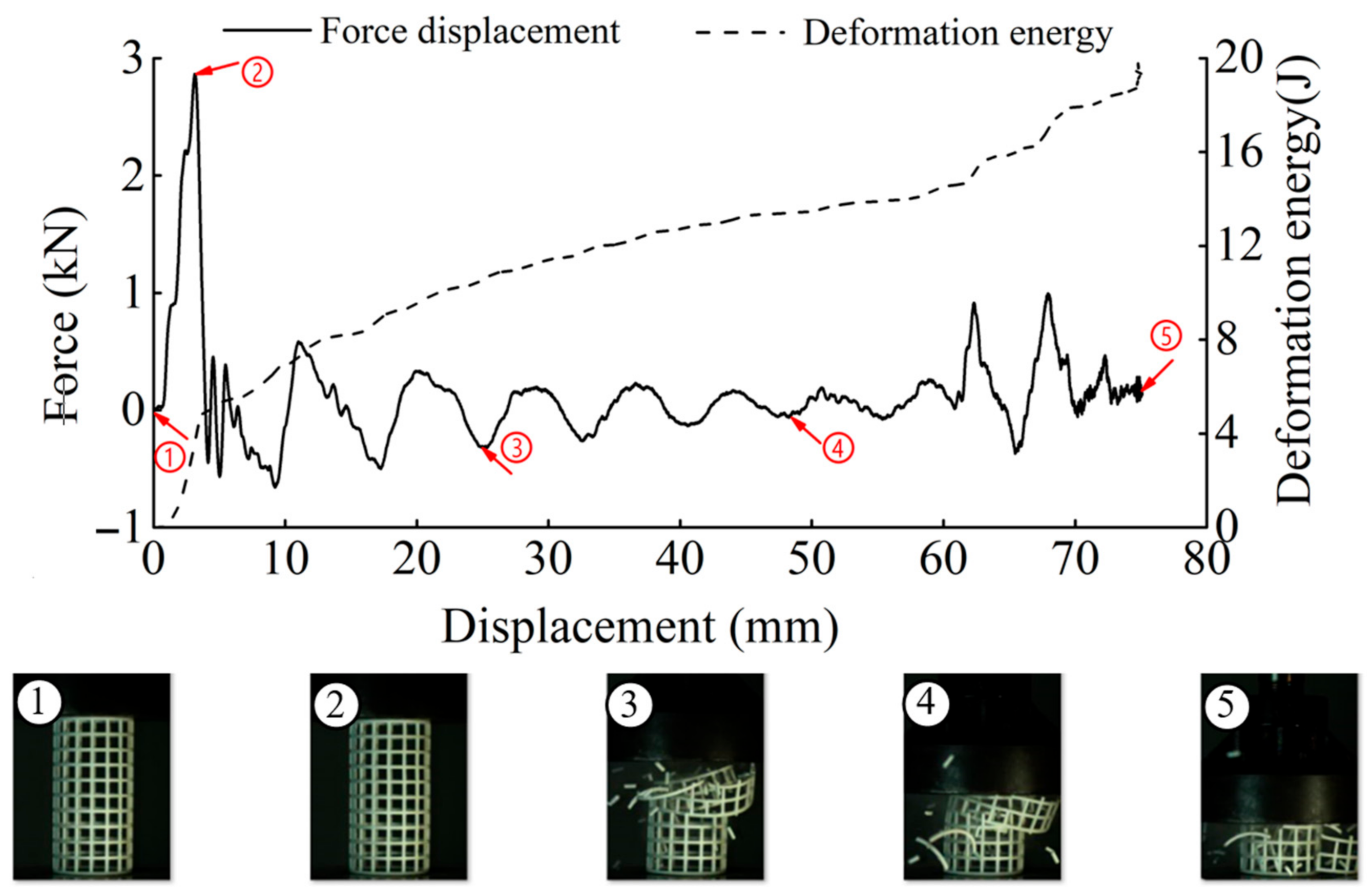
| Specimen | h/l0 | W (5 mm) | W (15 mm) | W (40 mm) | W (60 mm) |
|---|---|---|---|---|---|
| CSHT0 | 0 | 5.2 J | 8.2 J | 12.7 J | 14.5 J |
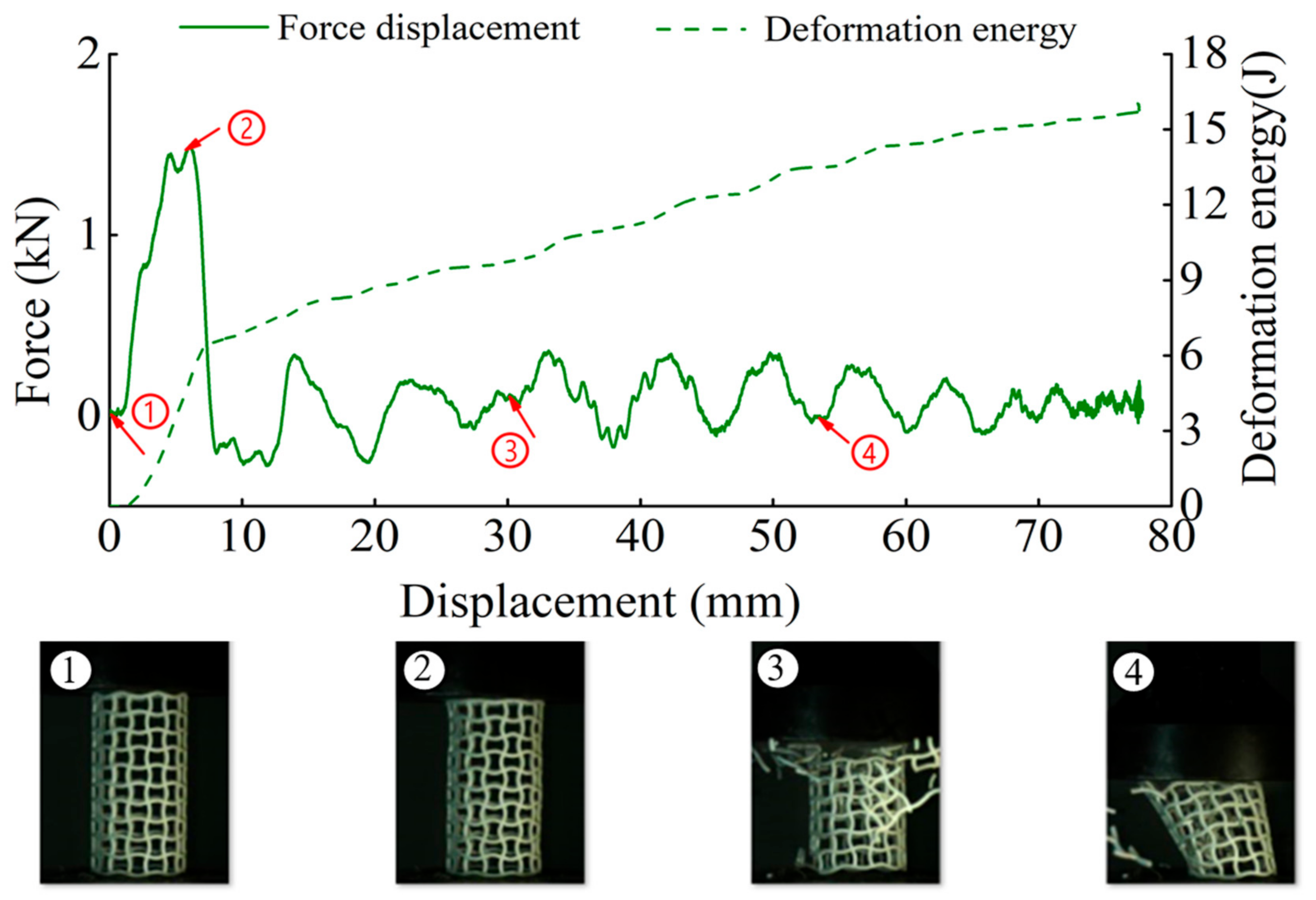
| CCHT1 | 0.1 | 3.3 J | 8.0 J | 11.2 J | 14.5 J |
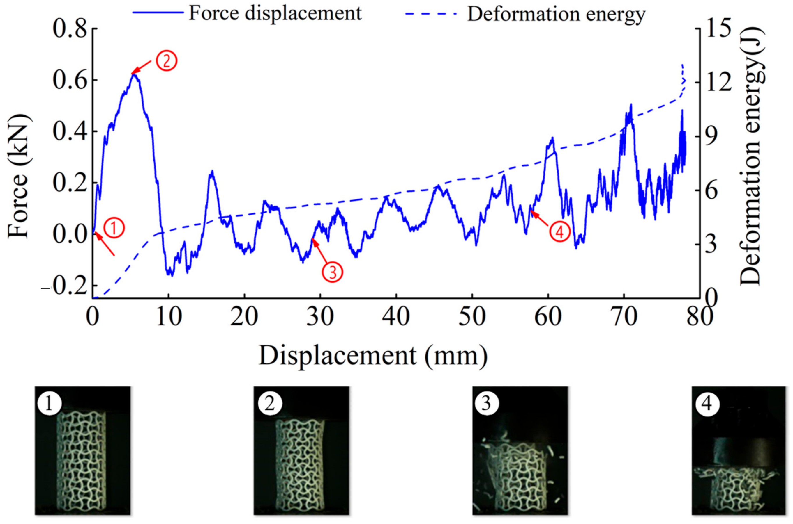
| CCHT2 | 0.2 | 1.4 J | 5.2 J | 7.2 J | 8.4 J |
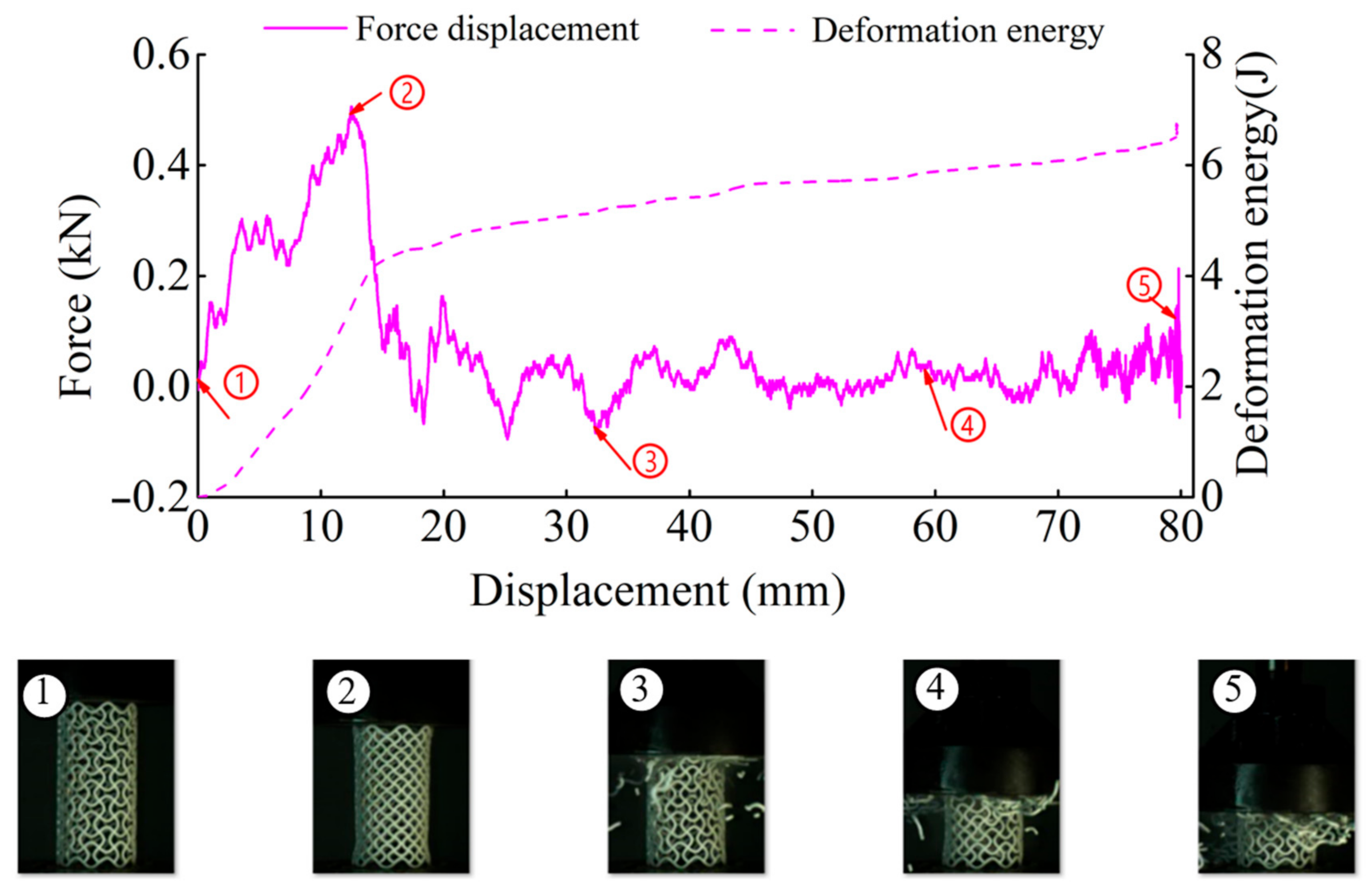
| CCHT3 | 0.3 | 0.9 J | 4.2 J | 5.4 J | 5.9 J |
Publisher’s Note: MDPI stays neutral with regard to jurisdictional claims in published maps and institutional affiliations. |
© 2021 by the authors. Licensee MDPI, Basel, Switzerland. This article is an open access article distributed under the terms and conditions of the Creative Commons Attribution (CC BY) license (http://creativecommons.org/licenses/by/4.0/).
Share and Cite
Guo, C.; Zhao, D.; Liu, Z.; Ding, Q.; Gao, H.; Yan, Q.; Sun, Y.; Ren, F. The 3D-Printed Honeycomb Metamaterials Tubes with Tunable Negative Poisson’s Ratio for High-Performance Static and Dynamic Mechanical Properties. Materials 2021, 14, 1353. https://doi.org/10.3390/ma14061353
Guo C, Zhao D, Liu Z, Ding Q, Gao H, Yan Q, Sun Y, Ren F. The 3D-Printed Honeycomb Metamaterials Tubes with Tunable Negative Poisson’s Ratio for High-Performance Static and Dynamic Mechanical Properties. Materials. 2021; 14(6):1353. https://doi.org/10.3390/ma14061353
Chicago/Turabian StyleGuo, Chunxia, Dong Zhao, Zhanli Liu, Qian Ding, Haoqiang Gao, Qun Yan, Yongtao Sun, and Fuguang Ren. 2021. "The 3D-Printed Honeycomb Metamaterials Tubes with Tunable Negative Poisson’s Ratio for High-Performance Static and Dynamic Mechanical Properties" Materials 14, no. 6: 1353. https://doi.org/10.3390/ma14061353
APA StyleGuo, C., Zhao, D., Liu, Z., Ding, Q., Gao, H., Yan, Q., Sun, Y., & Ren, F. (2021). The 3D-Printed Honeycomb Metamaterials Tubes with Tunable Negative Poisson’s Ratio for High-Performance Static and Dynamic Mechanical Properties. Materials, 14(6), 1353. https://doi.org/10.3390/ma14061353